EP4582296A1 - Ground power supply device and wiring - Google Patents
Ground power supply device and wiring Download PDFInfo
- Publication number
- EP4582296A1 EP4582296A1 EP23859831.2A EP23859831A EP4582296A1 EP 4582296 A1 EP4582296 A1 EP 4582296A1 EP 23859831 A EP23859831 A EP 23859831A EP 4582296 A1 EP4582296 A1 EP 4582296A1
- Authority
- EP
- European Patent Office
- Prior art keywords
- wiring
- power supply
- resonance
- power
- power transmission
- Prior art date
- Legal status (The legal status is an assumption and is not a legal conclusion. Google has not performed a legal analysis and makes no representation as to the accuracy of the status listed.)
- Pending
Links
Images



Classifications
-
- B—PERFORMING OPERATIONS; TRANSPORTING
- B60—VEHICLES IN GENERAL
- B60L—PROPULSION OF ELECTRICALLY-PROPELLED VEHICLES; SUPPLYING ELECTRIC POWER FOR AUXILIARY EQUIPMENT OF ELECTRICALLY-PROPELLED VEHICLES; ELECTRODYNAMIC BRAKE SYSTEMS FOR VEHICLES IN GENERAL; MAGNETIC SUSPENSION OR LEVITATION FOR VEHICLES; MONITORING OPERATING VARIABLES OF ELECTRICALLY-PROPELLED VEHICLES; ELECTRIC SAFETY DEVICES FOR ELECTRICALLY-PROPELLED VEHICLES
- B60L53/00—Methods of charging batteries, specially adapted for electric vehicles; Charging stations or on-board charging equipment therefor; Exchange of energy storage elements in electric vehicles
- B60L53/10—Methods of charging batteries, specially adapted for electric vehicles; Charging stations or on-board charging equipment therefor; Exchange of energy storage elements in electric vehicles characterised by the energy transfer between the charging station and the vehicle
- B60L53/12—Inductive energy transfer
- B60L53/122—Circuits or methods for driving the primary coil, e.g. supplying electric power to the coil
-
- B—PERFORMING OPERATIONS; TRANSPORTING
- B60—VEHICLES IN GENERAL
- B60L—PROPULSION OF ELECTRICALLY-PROPELLED VEHICLES; SUPPLYING ELECTRIC POWER FOR AUXILIARY EQUIPMENT OF ELECTRICALLY-PROPELLED VEHICLES; ELECTRODYNAMIC BRAKE SYSTEMS FOR VEHICLES IN GENERAL; MAGNETIC SUSPENSION OR LEVITATION FOR VEHICLES; MONITORING OPERATING VARIABLES OF ELECTRICALLY-PROPELLED VEHICLES; ELECTRIC SAFETY DEVICES FOR ELECTRICALLY-PROPELLED VEHICLES
- B60L53/00—Methods of charging batteries, specially adapted for electric vehicles; Charging stations or on-board charging equipment therefor; Exchange of energy storage elements in electric vehicles
- B60L53/30—Constructional details of charging stations
- B60L53/35—Means for automatic or assisted adjustment of the relative position of charging devices and vehicles
- B60L53/36—Means for automatic or assisted adjustment of the relative position of charging devices and vehicles by positioning the vehicle
-
- B—PERFORMING OPERATIONS; TRANSPORTING
- B60—VEHICLES IN GENERAL
- B60L—PROPULSION OF ELECTRICALLY-PROPELLED VEHICLES; SUPPLYING ELECTRIC POWER FOR AUXILIARY EQUIPMENT OF ELECTRICALLY-PROPELLED VEHICLES; ELECTRODYNAMIC BRAKE SYSTEMS FOR VEHICLES IN GENERAL; MAGNETIC SUSPENSION OR LEVITATION FOR VEHICLES; MONITORING OPERATING VARIABLES OF ELECTRICALLY-PROPELLED VEHICLES; ELECTRIC SAFETY DEVICES FOR ELECTRICALLY-PROPELLED VEHICLES
- B60L53/00—Methods of charging batteries, specially adapted for electric vehicles; Charging stations or on-board charging equipment therefor; Exchange of energy storage elements in electric vehicles
- B60L53/30—Constructional details of charging stations
- B60L53/35—Means for automatic or assisted adjustment of the relative position of charging devices and vehicles
- B60L53/38—Means for automatic or assisted adjustment of the relative position of charging devices and vehicles specially adapted for charging by inductive energy transfer
- B60L53/39—Means for automatic or assisted adjustment of the relative position of charging devices and vehicles specially adapted for charging by inductive energy transfer with position-responsive activation of primary coils
-
- H—ELECTRICITY
- H02—GENERATION; CONVERSION OR DISTRIBUTION OF ELECTRIC POWER
- H02J—ELECTRIC POWER NETWORKS; CIRCUIT ARRANGEMENTS OR SYSTEMS FOR SUPPLYING OR DISTRIBUTING ELECTRIC POWER; SYSTEMS FOR STORING ELECTRIC ENERGY
- H02J50/00—Circuit arrangements or systems for wireless supply or distribution of electric power
- H02J50/10—Circuit arrangements or systems for wireless supply or distribution of electric power using inductive coupling
- H02J50/12—Circuit arrangements or systems for wireless supply or distribution of electric power using inductive coupling of the resonant type
-
- H—ELECTRICITY
- H02—GENERATION; CONVERSION OR DISTRIBUTION OF ELECTRIC POWER
- H02J—ELECTRIC POWER NETWORKS; CIRCUIT ARRANGEMENTS OR SYSTEMS FOR SUPPLYING OR DISTRIBUTING ELECTRIC POWER; SYSTEMS FOR STORING ELECTRIC ENERGY
- H02J50/00—Circuit arrangements or systems for wireless supply or distribution of electric power
- H02J50/40—Circuit arrangements or systems for wireless supply or distribution of electric power using two or more transmitting or receiving devices
-
- H—ELECTRICITY
- H02—GENERATION; CONVERSION OR DISTRIBUTION OF ELECTRIC POWER
- H02J—ELECTRIC POWER NETWORKS; CIRCUIT ARRANGEMENTS OR SYSTEMS FOR SUPPLYING OR DISTRIBUTING ELECTRIC POWER; SYSTEMS FOR STORING ELECTRIC ENERGY
- H02J50/00—Circuit arrangements or systems for wireless supply or distribution of electric power
- H02J50/40—Circuit arrangements or systems for wireless supply or distribution of electric power using two or more transmitting or receiving devices
- H02J50/402—Circuit arrangements or systems for wireless supply or distribution of electric power using two or more transmitting or receiving devices the two or more transmitting or the two or more receiving devices being integrated in the same unit, e.g. power mats with several coils or antennas with several sub-antennas
-
- H—ELECTRICITY
- H02—GENERATION; CONVERSION OR DISTRIBUTION OF ELECTRIC POWER
- H02J—ELECTRIC POWER NETWORKS; CIRCUIT ARRANGEMENTS OR SYSTEMS FOR SUPPLYING OR DISTRIBUTING ELECTRIC POWER; SYSTEMS FOR STORING ELECTRIC ENERGY
- H02J50/00—Circuit arrangements or systems for wireless supply or distribution of electric power
- H02J50/70—Circuit arrangements or systems for wireless supply or distribution of electric power involving the reduction of electric, magnetic or electromagnetic leakage fields
-
- H—ELECTRICITY
- H02—GENERATION; CONVERSION OR DISTRIBUTION OF ELECTRIC POWER
- H02J—ELECTRIC POWER NETWORKS; CIRCUIT ARRANGEMENTS OR SYSTEMS FOR SUPPLYING OR DISTRIBUTING ELECTRIC POWER; SYSTEMS FOR STORING ELECTRIC ENERGY
- H02J50/00—Circuit arrangements or systems for wireless supply or distribution of electric power
- H02J50/90—Circuit arrangements or systems for wireless supply or distribution of electric power involving detection or optimisation of position, e.g. alignment
-
- B—PERFORMING OPERATIONS; TRANSPORTING
- B60—VEHICLES IN GENERAL
- B60L—PROPULSION OF ELECTRICALLY-PROPELLED VEHICLES; SUPPLYING ELECTRIC POWER FOR AUXILIARY EQUIPMENT OF ELECTRICALLY-PROPELLED VEHICLES; ELECTRODYNAMIC BRAKE SYSTEMS FOR VEHICLES IN GENERAL; MAGNETIC SUSPENSION OR LEVITATION FOR VEHICLES; MONITORING OPERATING VARIABLES OF ELECTRICALLY-PROPELLED VEHICLES; ELECTRIC SAFETY DEVICES FOR ELECTRICALLY-PROPELLED VEHICLES
- B60L2270/00—Problem solutions or means not otherwise provided for
- B60L2270/10—Emission reduction
- B60L2270/14—Emission reduction of noise
- B60L2270/147—Emission reduction of noise electro magnetic [EMI]
-
- B—PERFORMING OPERATIONS; TRANSPORTING
- B60—VEHICLES IN GENERAL
- B60M—POWER SUPPLY LINES, AND DEVICES ALONG RAILS, FOR ELECTRICALLY- PROPELLED VEHICLES
- B60M7/00—Power lines or rails specially adapted for electrically-propelled vehicles of special types, e.g. suspension tramway, ropeway, underground railway
-
- H—ELECTRICITY
- H02—GENERATION; CONVERSION OR DISTRIBUTION OF ELECTRIC POWER
- H02J—ELECTRIC POWER NETWORKS; CIRCUIT ARRANGEMENTS OR SYSTEMS FOR SUPPLYING OR DISTRIBUTING ELECTRIC POWER; SYSTEMS FOR STORING ELECTRIC ENERGY
- H02J2105/00—Networks for supplying or distributing electric power characterised by their spatial reach or by the load
- H02J2105/30—Networks for supplying or distributing electric power characterised by their spatial reach or by the load the load networks being external to vehicles, i.e. exchanging power with vehicles
- H02J2105/33—Networks for supplying or distributing electric power characterised by their spatial reach or by the load the load networks being external to vehicles, i.e. exchanging power with vehicles exchanging power with road vehicles
- H02J2105/37—Networks for supplying or distributing electric power characterised by their spatial reach or by the load the load networks being external to vehicles, i.e. exchanging power with vehicles exchanging power with road vehicles exchanging power with electric vehicles [EV] or with hybrid electric vehicles [HEV]
-
- Y—GENERAL TAGGING OF NEW TECHNOLOGICAL DEVELOPMENTS; GENERAL TAGGING OF CROSS-SECTIONAL TECHNOLOGIES SPANNING OVER SEVERAL SECTIONS OF THE IPC; TECHNICAL SUBJECTS COVERED BY FORMER USPC CROSS-REFERENCE ART COLLECTIONS [XRACs] AND DIGESTS
- Y02—TECHNOLOGIES OR APPLICATIONS FOR MITIGATION OR ADAPTATION AGAINST CLIMATE CHANGE
- Y02T—CLIMATE CHANGE MITIGATION TECHNOLOGIES RELATED TO TRANSPORTATION
- Y02T10/00—Road transport of goods or passengers
- Y02T10/60—Other road transportation technologies with climate change mitigation effect
- Y02T10/70—Energy storage systems for electromobility, e.g. batteries
-
- Y—GENERAL TAGGING OF NEW TECHNOLOGICAL DEVELOPMENTS; GENERAL TAGGING OF CROSS-SECTIONAL TECHNOLOGIES SPANNING OVER SEVERAL SECTIONS OF THE IPC; TECHNICAL SUBJECTS COVERED BY FORMER USPC CROSS-REFERENCE ART COLLECTIONS [XRACs] AND DIGESTS
- Y02—TECHNOLOGIES OR APPLICATIONS FOR MITIGATION OR ADAPTATION AGAINST CLIMATE CHANGE
- Y02T—CLIMATE CHANGE MITIGATION TECHNOLOGIES RELATED TO TRANSPORTATION
- Y02T10/00—Road transport of goods or passengers
- Y02T10/60—Other road transportation technologies with climate change mitigation effect
- Y02T10/7072—Electromobility specific charging systems or methods for batteries, ultracapacitors, supercapacitors or double-layer capacitors
-
- Y—GENERAL TAGGING OF NEW TECHNOLOGICAL DEVELOPMENTS; GENERAL TAGGING OF CROSS-SECTIONAL TECHNOLOGIES SPANNING OVER SEVERAL SECTIONS OF THE IPC; TECHNICAL SUBJECTS COVERED BY FORMER USPC CROSS-REFERENCE ART COLLECTIONS [XRACs] AND DIGESTS
- Y02—TECHNOLOGIES OR APPLICATIONS FOR MITIGATION OR ADAPTATION AGAINST CLIMATE CHANGE
- Y02T—CLIMATE CHANGE MITIGATION TECHNOLOGIES RELATED TO TRANSPORTATION
- Y02T90/00—Enabling technologies or technologies with a potential or indirect contribution to GHG emissions mitigation
- Y02T90/10—Technologies relating to charging of electric vehicles
- Y02T90/14—Plug-in electric vehicles
Definitions
- the present disclosure relates to a ground power supply device and a wiring.
- a ground power supply device which includes a plurality of coils for transmitting a power in a wireless manner and one power supply that supplies the power to the coil, and in which the coils and the power supply are connected to each other by a conductor ( JP 2019-526219 A ).
- an object of the present disclosure is to suppress a difference in resonance frequency among a plurality of coils connected to one power supply.
- the gist of the present disclosure is as follows:
- FIG. 1 is a diagram schematically illustrating the ground power supply device 1 according to the first embodiment and the vehicle 5.
- the ground power supply device 1 transmits the power to the vehicle 5 by wireless power transmission by magnetic field resonance coupling (magnetic field resonance).
- magnetic field resonance magnetic field resonance
- the present embodiment when the vehicle 5 is traveling, wireless power transmission is performed from the ground power supply device 1 to the vehicle 5.
- travelling means a state where the vehicle 5 is located on the road for traveling. Therefore, the term “traveling” includes not only a state where the vehicle 5 is actually running at any speed greater than zero, but also a state where the vehicle 5 is stopped on the road, for example, by waiting for a traffic light.
- the ground power supply device 1 includes a plurality of power transmission units 21 embedded in a road (underground) on which the vehicle 5 travels. As illustrated in Fig. 1 , in the present embodiment, the power transmission unit 21 is disposed at predetermined intervals along each of lanes 100 at the center of each of the lanes 100 on which the vehicle 5 travels.
- the controller 30 is, for example, a general-purpose computer, and performs various controls of the ground power supply device 1.
- the controller 30 is electrically connected to the inverter 12 of the power supply unit 10, and controls the inverter 12 to control power transmission by the power transmission unit 21.
- the controller 30 specifies the power transmission unit 21 on which the vehicle 5 including the power reception device 50 is traveling based on an output from an arbitrary sensor (not illustrated), and controls the inverter 12 to supply the power to the specified power transmission unit 21.
- the controller 30 includes a processor that executes various processes, and a memory that stores a program for the processor to execute various processes, various data used when the processor executes various processes, and the like.
- the power reception device 50 receives the power from the power transmission unit 21 and supplies the received power to the battery 42.
- the power reception device 50 includes a power reception-side resonance circuit 51, a power reception-side rectifier circuit 54, and a charging circuit 55.
- the power reception-side resonance circuit 51 is disposed at a bottom of the vehicle 5 so that a distance from the road surface is small.
- the power reception-side resonance circuit 51 has a configuration similar to that of the power transmission unit 21, and includes a power reception-side coil 52 and a power reception-side capacitor 53.
- the power reception-side coil 52 is configured such that a current flows through the power reception-side coil 52 when a magnetic field is generated around the power reception-side coil 52.
- the power reception-side coil 52 and the power reception-side capacitor 53 constitute a resonator.
- the outer diameter and inner diameter of the power reception-side coil 52, the number of turns of the power reception-side coil 52, the electrostatic capacitance of the power reception-side capacitor 53, and the like) of the power reception-side coil 52 and the power reception-side capacitor 53 are determined such that the resonance frequency of the power reception-side resonance circuit 51 matches the resonance frequency of the power transmission unit 21.
- the power reception-side rectifier circuit 54 is electrically connected to the power reception-side resonance circuit 51 and the charging circuit 55.
- the power reception-side rectifier circuit 54 rectifies the AC power supplied from the power reception-side resonance circuit 51 to convert the AC power into the DC power, and supplies the DC power to the charging circuit 55.
- the power reception-side rectifier circuit 54 is, for example, an AC/DC converter.
- the charging circuit 55 is electrically connected to the power reception-side rectifier circuit 54 and the battery 42.
- the charging circuit 55 converts the DC power supplied from the power reception-side rectifier circuit 54 into a voltage level of the battery 42, and supplies the DC power to the battery 42.
- the charging circuit 55 is, for example, a DC/DC converter.
- Fig. 3 is a diagram schematically illustrating a configuration of the ground power supply device 1.
- Fig. 3 illustrates a state where the plurality of power transmission-side resonance circuits 20 are connected to one power supply unit 10.
- reference numeral 20 only one of the plurality of power transmission-side resonance circuits 20 is denoted by reference numeral 20.
- the plurality of power transmission units 21 connected to one power supply unit 10 are arranged in a line along the lane in the road.
- Each of the power transmission units 21 and the power supply unit 10 are connected by the wiring 22 of the power transmission-side resonance circuits 20 different from each other.
- the wiring 22 connecting each of the power transmission units 21 and the power supply unit 10 has two conducting wires through which currents flow in opposite directions.
- an interval between each of the plurality of power transmission units 21 arranged in a line and one power supply unit 10 is different from each other.
- each of the power transmission units 21 and the power supply unit 10 are connected by one wiring 22 disposed without generating slack therebetween. Therefore, the plurality of wirings 22, each of which connects each of the power transmission units 21 and the power supply unit 10 have different lengths.
- the wiring 22 of each of the power transmission-side resonance circuits 20 has a length different from the length of the wiring 22 of the other power transmission-side resonance circuit 20.
- the power transmission-side resonance circuit 20 is provided with a resonance compensation capacitor 25.
- the resonance compensation capacitor 25 is connected in series with the wiring 22 in the middle of the wiring 22.
- each of the wiring 22 includes the resonance compensation capacitor 25.
- the resonance compensation capacitor 25 is connected to one of the two conducting wires of each of the wirings 22.
- the resonance compensation capacitor 25 has different electrostatic capacitance according to the length of the wiring 22 of the power transmission-side resonance circuit 20 in which the resonance compensation capacitor 25 is provided. Specifically, the electrostatic capacitance of the resonance compensation capacitor 25 decreases as the length of the wiring 22 increases. More specifically, the resonance compensation capacitor 25 has such electrostatic capacitance that the resonance frequency of the power transmission-side resonance circuit 20 is equal to the frequency of the AC power supplied by the power supply unit 10 even when the parasitic inductances parasitic on the wiring 22 of the power transmission-side resonance circuit 20 are different from each other.
- the resonance frequency of the power transmission-side resonance circuit 20 can be made equal to the frequency of the AC power supplied by the power supply unit 10. Therefore, according to the present embodiment, even in such a case, the resonance frequencies of all the power transmission-side resonance circuits 20 can be made substantially the same, and the resonance frequencies of all the power transmission-side resonance circuits 20 can be made equal to the resonance frequency of the power reception-side resonance circuit 51 of the vehicle 5. Thus, according to the present embodiment, transmission efficiency between the power transmission unit 21 and the power reception-side resonance circuit 51 can be increased.
- the resonance compensation capacitor 25 is connected in series with the wiring 22 in the middle of the wiring 22.
- the resonance compensation capacitor 25 may be provided between the wiring 22 and the power transmission unit 21 or between the wiring 22 and the inverter 12 of the power supply unit 10.
- the resonance compensation capacitor 25 may be provided in the power transmission unit 21 (for example, between the power transmission-side coil 23 and the power transmission-side capacitor 24 of the power transmission unit 21) as long as the resonance compensation capacitor 25 is connected in series in the power transmission-side resonance circuit 20.
- one resonance compensation capacitor 25 is provided in one power transmission-side resonance circuit 20.
- a plurality of the resonance compensation capacitors 25 may be provided in one power transmission-side resonance circuit 20.
- the resonance compensation capacitor 25 is connected to one of the two conducting wires of each of the wirings 22.
- the resonance compensation capacitor 25 may be connected to each of the two conducting wires of each of the wirings 22.
- the electrostatic capacitance of the resonance compensation capacitor 25 is set to such a value that the resonance frequency of the power transmission-side resonance circuit 20 is equal to the frequency of the AC power supplied by the power supply unit 10.
- ground power supply device 1 according to a second embodiment will be described with reference to Fig. 5 .
- the configuration of the ground power supply device 1 according to the second embodiment is basically similar to the configuration of the ground power supply device 1 according to the first embodiment.
- portions different from the configuration of the ground power supply device 1 according to the first embodiment will be mainly described.
- Fig. 5 is a diagram similar to Figs. 3 and 4 , schematically illustrating a configuration of the ground power supply device 1 according to the second embodiment. Also in the present embodiment, one power transmission unit 21 and one wiring 22 constitute one power transmission-side resonance circuit 20. Also in Fig. 5 , the plurality of power transmission-side resonance circuits 20 are connected to one power supply unit 10.
- each of the wirings 22 has two portions including a first wiring portion 22a and a second wiring portion 22b.
- the first wiring portion 22a of each of the wirings 22 is connected to the corresponding power transmission unit 21 and a first connector 26.
- the plurality of first wiring portions 22a connected to the plurality of power transmission units 21 arranged adjacent to each other are connected to one first connector 26 (in the example illustrated in Fig. 5 , the four first wiring portions 22a). Therefore, one first connector 26 is connected to the plurality of power transmission units 21 arranged adjacent to each other.
- all the first wiring portions 22a have the same length. Therefore, regarding the first wiring portion 22a, there is no difference in magnitude of parasitic inductance between the power transmission-side resonance circuits 20.
- the second wiring portion 22b of each of the wirings 22 is connected to a corresponding second connector 27 and the power supply unit 10.
- a plurality of the second wiring portions 22b of one group having the same length are connected to one second connector 27 (in the example illustrated in Fig. 5 , the four second wiring portions 22b).
- the second wiring portions 22b of the same number as the number of the first wiring portions 22a connected to the first connector 26 are connected to the second connector 27.
- the second connector 27 is connected to the first connector 26, whereby the second wiring portion 22b is connected to the corresponding first wiring portion 22a.
- the plurality of second wiring portions 22b having the same length are connected to the first wiring portion 22a via the same first connector 26 and the same second connector 27.
- all the wirings 22 of the power transmission-side resonance circuits 20 including the second wiring portions 22b having the same length have the same length, and thus have the same parasitic inductance.
- the resonance compensation capacitor 25 provided in the second wiring portion 22b has the same electrostatic capacitance as described above, the resonance frequencies of the power transmission-side resonance circuits 20 can be made equal.
- the first wiring portion 22a has the same length.
- one first connector 26 and the plurality of first wiring portions 22a connected thereto have the same configuration. Therefore, parts can be shared in manufacturing the first connector 26 and the first wiring portion 22a.
- the second wiring portion 22b connected to one second connector 27 has the same configuration. Therefore, the number of variations in the length of the second wiring portion 22b and the number of variations in the resonance compensation capacitor 25 can be reduced with respect to the number of the power transmission units 21, and thus, while the manufacturing cost can be reduced, the ground power supply device 1 can be easily laid.
- the power transmission units 21 are arranged at different positions from each other, the first wiring portions 22a connected to the plurality of power transmission units 21 are connected to the second wiring portion 22b at the same point by the first connector 26 and the second connector 27, so that the wiring can be easily wired.
- the resonance compensation capacitor 25 is not provided in the first wiring portion 22a. Therefore, in the present embodiment, the electrostatic capacitance of the resonance compensation capacitor 25 provided in the second wiring portion 22b is set in consideration of the length of the wiring 22 including the first wiring portion 22a and the second wiring portion 22b. Furthermore, in the present embodiment, since the length of the first wiring portion 22a is the same in all the power transmission-side resonance circuits 20, the electrostatic capacitance of the resonance compensation capacitor 25 provided in the second wiring portion 22b and the electrostatic capacitance of the power transmission-side capacitor 24 of the power transmission unit 21 can be set in consideration of the parasitic inductance generated in the first wiring portion 22a. Since the first wiring portion 22a does not include the resonance compensation capacitor 25 as described above, the first wiring portion 22a can have a simple configuration.
- one second wiring portion 22c is connected to one changeover switch 28. Therefore, one second wiring portion 22c is connected to the plurality of first wiring portions 22a via the changeover switch 28. The plurality of second wiring portions 22c are connected to the changeover switches 28 different from each other and one common power supply unit 10. In the present embodiment, one second wiring portion 22c is shared by the plurality of power transmission-side resonance circuits 20. In any case, also in the present embodiment, one power transmission unit 21 and one wiring 22 constitute one power transmission-side resonance circuit 20.
- the changeover switch 28 is connected to the controller 30 and controlled by the controller 30.
- the controller 30 specifies the power transmission unit 21 on which the vehicle 5 including the power reception device 50 is traveling based on the output from an arbitrary sensor (not illustrated), and switches the changeover switch 28 so that the specified power transmission unit 21 and the power supply unit 10 are connected.
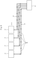
- Fig. 8 is a diagram schematically illustrating a configuration of the ground power supply device 1 according to the fourth embodiment.
- each of the wirings 22 connects one power transmission unit 21 and the power supply unit 10.
- the wirings 22 have different lengths.
- each of the wirings 22 is configured by connecting the plurality of wiring modules 29 in series. As described above, since the cables 35 of all the wiring modules 29 have the same length, the length of the wiring 22 is different as the number of the wiring modules 29 constituting the wiring 22 is different. Therefore, the wiring 22 used for the power transmission unit 21 whose distance from the power supply unit 10 is longer is configured by a larger number of wiring modules 29.
- all the wirings 22 are configured by the plurality of wiring modules 29 having the same configuration. Therefore, it is not necessary to use a wiring having an individual configuration including a resonance compensation capacitor having a different electrostatic capacitance for each of the wirings 22 having different lengths. Thus, the wiring 22 can be easily manufactured, and the wiring 22 can be easily wired when the power transmission-side resonance circuit 20 is laid.
- all the wirings 22 extending from the power supply unit 10 to each of the power transmission units 21 are formed by the wiring module 29.
- only a part of each of the wiring 22 may be formed by the wiring module 29.
- only the second wiring portions 22b or 22c may be formed by connecting the wiring modules 29 in series, and the first wiring portions 22a may be formed without using the wiring module 29.
- the length of the cables 35 of all the wiring modules 29 is an integral multiple of twice or more the interval (in particular, the interval between the power transmission-side coils 23 arranged adjacent to each other) of the power transmission units 21 arranged adjacent to each other.
- the length of the cables 35 of all the wiring modules 29 is four times the interval between the power transmission units 21 arranged adjacent to each other.
Landscapes
- Engineering & Computer Science (AREA)
- Power Engineering (AREA)
- Computer Networks & Wireless Communication (AREA)
- Transportation (AREA)
- Mechanical Engineering (AREA)
- Physics & Mathematics (AREA)
- Electromagnetism (AREA)
- Electric Propulsion And Braking For Vehicles (AREA)
- Current-Collector Devices For Electrically Propelled Vehicles (AREA)
- Charge And Discharge Circuits For Batteries Or The Like (AREA)
Abstract
Description
- The present disclosure relates to a ground power supply device and a wiring.
- There is known a ground power supply device which includes a plurality of coils for transmitting a power in a wireless manner and one power supply that supplies the power to the coil, and in which the coils and the power supply are connected to each other by a conductor (
JP 2019-526219 A - Since a distance between the power supply and the coil is different for each coil, the lengths of the conductors connecting the power supply and the coil are different from each other. Since inductance parasitic on the conductor varies, depending on the length of the conductor, a resonance frequency varies for each resonance circuit including the coil and the conductor having different length.
- In view of the above problems, an object of the present disclosure is to suppress a difference in resonance frequency among a plurality of coils connected to one power supply.
- The gist of the present disclosure is as follows:
-
- (1) A ground power supply device that transmits power to a vehicle in a wireless manner, the ground power supply device comprising:
- a plurality of resonance circuits; and
- one power supply source that supplies AC power having the same frequency to all the resonance circuits, wherein
- each of the resonance circuits includes a coil embedded in a road and configured to transmit the power in a wireless manner, and a wiring connecting each of the coils and the power supply source,
- the wiring of each of the resonance circuits has a length at least partially different from the wiring of another resonance circuit, and inductance parasitic on the wiring is formed to be at least partially different from the wiring of the other resonance circuit due to a difference in length, and
- the resonance circuit further includes a capacitor having a different electrostatic capacitance in such a way that resonance frequencies of all the resonance circuits become equal when the inductance parasitic on the wiring is different.
- (2) The ground power supply device according to above (1), wherein the capacitor has such electrostatic capacitance that the resonance frequencies of all the resonance circuits are the same as the frequency of the AC power when the inductance parasitic on the wiring is different.
- (3) The ground power supply device according to above (1) or (2), wherein the wirings of the plurality of resonance circuits including a plurality of coils arranged adjacent to each other have the same length.
- (4) The ground power supply device according to any one of above (1) to (3), wherein
- the wiring includes a first portion having the same length in all the resonance circuits and a second portion having a partially different length between the resonance circuits, and
- the second portion includes the capacitor.
- (5) The ground power supply device according to above (4), wherein the capacitors provided in a plurality of the second portions having the same length have the same electrostatic capacitance.
- (6) The ground power supply device according to above (4), wherein the first portion does not include the capacitor.
- (7) The ground power supply device according to above (4) or (5), wherein the first portion is connected to the coil, the second portion is connected to the power supply source, and a plurality of the second portions having the same length are connected to the first portion by the same connector.
- (8) The ground power supply device according to any one of above (1) to (7), wherein
- the wiring is configured at least partially by connecting a plurality of wiring modules in series, the wiring modules each including a cable having the same length and a capacitor connected to the cable,
- the capacitor of each of the wiring modules has such electrostatic capacitance that cancels an influence on a resonance frequency generated in the coil at a frequency of the AC power due to inductance parasitic on the cable of the wiring module, and
- in the resonance circuit including wiring having a different length, the length of the wiring is different due to a difference in the number of the wiring modules constituting the wiring of the resonance circuit.
- (9) The ground power supply device according to above (8), wherein the length of the cable of the wiring module is equal to an integral multiple of an interval between the coils adjacent to each other.
-
-
Fig. 1 is a diagram schematically illustrating a ground power supply device and a vehicle according to a first embodiment. -
Fig. 2 is a diagram schematically illustrating a configuration of the ground power supply device and the vehicle according to the first embodiment. -
Fig. 3 is a diagram schematically illustrating the configuration of the ground power supply device according to the first embodiment. -
Fig. 4 is a diagram similar toFig. 3 , schematically illustrating a configuration of the ground power supply device according to a modification of the first embodiment. -
Fig. 5 is a diagram similar toFigs. 3 and4 , schematically illustrating a configuration of a ground power supply device according to a second embodiment. -
Fig. 6 is a diagram similar toFigs. 3 to 5 , schematically illustrating a configuration of a ground power supply device according to a third embodiment. -
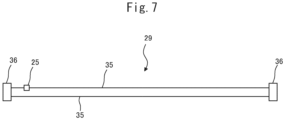
Fig. 7 is a diagram schematically illustrating a configuration of each wiring module. -
Fig. 8 is a diagram schematically illustrating a configuration of a ground power supply device according to a fourth embodiment. - Hereinafter, embodiments will be described in detail with reference to the drawings. In the following description, similar components are denoted by the same reference numerals.
- With reference to
Fig. 1 , an outline of a ground power supply device 1 according to a first embodiment and avehicle 5 capable of receiving power from the ground power supply device 1 will be described.Fig. 1 is a diagram schematically illustrating the ground power supply device 1 according to the first embodiment and thevehicle 5. The ground power supply device 1 transmits the power to thevehicle 5 by wireless power transmission by magnetic field resonance coupling (magnetic field resonance). In particular, in the present embodiment, when thevehicle 5 is traveling, wireless power transmission is performed from the ground power supply device 1 to thevehicle 5. - The term "traveling" means a state where the
vehicle 5 is located on the road for traveling. Therefore, the term "traveling" includes not only a state where thevehicle 5 is actually running at any speed greater than zero, but also a state where thevehicle 5 is stopped on the road, for example, by waiting for a traffic light. - The ground power supply device 1 includes a plurality of
power transmission units 21 embedded in a road (underground) on which thevehicle 5 travels. As illustrated inFig. 1 , in the present embodiment, thepower transmission unit 21 is disposed at predetermined intervals along each oflanes 100 at the center of each of thelanes 100 on which thevehicle 5 travels. - Next, a configuration of the ground power supply device 1 will be schematically described with reference to
Fig. 2. Fig. 2 is a diagram schematically illustrating a configuration of the ground power supply device 1 and thevehicle 5. As illustrated inFig. 2 , the ground power supply device 1 includes apower source 2, apower supply unit 10, a plurality of power transmission-side resonance circuits 20 including thepower transmission unit 21, and acontroller 30. The power transmission-side resonance circuit 20 including thepower transmission unit 21 is embedded in the road (underground). On the other hand, thepower supply unit 10 and thecontroller 30 may be embedded in the road, or may be arranged in a place (including the ground) different from the road. In the present embodiment, onepower supply unit 10 is connected to a plurality of power transmission-side resonance circuits 20. - The
power source 2 supplies the power to thepower transmission unit 21 via thepower supply unit 10. Thepower source 2 is, for example, a commercial AC power source that supplies single-layer AC power. Thepower source 2 may be another AC power supply that supplies three-phase AC power, or may be a DC power supply such as a fuel cell. - The
power supply unit 10 converts AC power supplied from thepower source 2 into a high-frequency AC power to be supplied to the power transmission-side resonance circuit 20. Thepower supply unit 10 includes a power transmission-side rectifier circuit 11 and aninverter 12. In thepower supply unit 10, the AC power supplied from thepower source 2 is rectified in the power transmission-side rectifier circuit 11 and converted into a DC current, and this DC current is converted into the AC power in theinverter 12. Thepower source 2 and thepower supply unit 10 function as a power supply source that supplies the AC power to the power transmission-side resonance circuit 20. - The power transmission-
side rectifier circuit 11 is electrically connected to thepower source 2 and theinverter 12. The power transmission-side rectifier circuit 11 rectifies an AC power supplied from thepower source 2 to convert the AC power into a DC power, and supplies the DC power to theinverter 12. The power transmission-side rectifier circuit 11 is, for example, an AC/DC converter. In the present embodiment, onepower supply unit 10 is provided with one power transmission-side rectifier circuit 11. When thepower source 2 is the DC power supply, the power transmission-side rectifier circuit 11 may be omitted. - The
inverter 12 is electrically connected to the power transmission-side rectifier circuit 11 and the power transmission-side resonance circuit 20. Theinverter 12 converts the DC power supplied from the power transmission-side rectifier circuit 11 into AC power (high-frequency AC power) having a higher frequency than that of the AC power of thepower source 2, and supplies the high-frequency AC power to the power transmission-side resonance circuit 20. In the present embodiment, thepower supply unit 10 includes theinverters 12 corresponding in number to the power transmission-side resonance circuit 20. Each of theinverters 12 is connected to one of the corresponding power transmission-side resonance circuits 20 different from each other. In addition, each of theinverters 12 supplies AC power having the same frequency as each other to the power transmission-side resonance circuit 20. Therefore, thepower supply unit 10 supplies the AC power having the same frequency to all the power transmission-side resonance circuits 20. - The power transmission-
side resonance circuit 20 includes apower transmission unit 21 and awiring 22. The power transmission-side resonance circuit 20 is connected to thepower supply unit 10, and generates an alternating magnetic field when a high-frequency AC power is supplied from thepower supply unit 10. - The
power transmission unit 21 includes a power transmission-side coil 23 and a power transmission-side capacitor 24. The power transmission-side coil 23 generates a magnetic field to transmit the power in a wireless manner, when a current flows the power transmission-side coil 23. The power transmission-side coil 23 and the power transmission-side capacitor 24 constitute a resonator. Various parameters (the outer diameter and inner diameter of the power transmission-side coil 23, the number of turns of the power transmission-side coil 23, electrostatic capacitance of the power transmission-side capacitor 24, and the like) of the power transmission-side coil 23 and the power transmission-side capacitor 24 are determined such that a resonance frequency of thepower transmission unit 21 becomes a predetermined set value. The predetermined set value is, for example, from 10 kHz to 100 GHz, and is preferably 85 kHz defined by the SAE TIR J2954 standard as a frequency band for wireless power transmission. In the present embodiment, all thepower transmission units 21 are configured such that various parameters of the power transmission-side coil 23 and the power transmission-side capacitor 24 are the same. In other words, all thepower transmission units 21 have the same configuration. - As described above, the
power transmission unit 21 is embedded in the road, so that the power transmission-side coil 23 and the power transmission-side capacitor 24 are also embedded in the road. Thepower transmission unit 21 is disposed at the center of the lane through which thevehicle 5 passes such that the center of the power transmission-side coil 23 is located at the center of the lane. When a high-frequency power is supplied from theinverter 12 to thepower transmission unit 21 via thewiring 22, the power transmission-side coil 23 of thepower transmission unit 21 generates an alternating magnetic field for power transmission. - The
wiring 22 is used to connect theinverter 12 of thepower supply unit 10 and the power transmission unit 21 (i.e., the power transmission-side coil 23). In the present embodiment, the ground power supply device 1 includes the plurality ofpower transmission units 21 and the plurality ofinverters 12 corresponding to thepower transmission units 21 different from each other. Each of thewirings 22 connects oneinverter 12 and one correspondingpower transmission unit 21. - The
controller 30 is, for example, a general-purpose computer, and performs various controls of the ground power supply device 1. For example, thecontroller 30 is electrically connected to theinverter 12 of thepower supply unit 10, and controls theinverter 12 to control power transmission by thepower transmission unit 21. Specifically, for example, thecontroller 30 specifies thepower transmission unit 21 on which thevehicle 5 including thepower reception device 50 is traveling based on an output from an arbitrary sensor (not illustrated), and controls theinverter 12 to supply the power to the specifiedpower transmission unit 21. Thecontroller 30 includes a processor that executes various processes, and a memory that stores a program for the processor to execute various processes, various data used when the processor executes various processes, and the like. - Next, a configuration of the
vehicle 5 will be schematically described with reference toFig. 2 . As illustrated inFig. 2 , thevehicle 5 includes amotor 41, abattery 42, a power control unit (PCU) 43, apower reception device 50, and an electronic control unit (ECU) 45. Thevehicle 5 is an electric vehicle (BEV) in which themotor 41 drives thevehicle 5, or a hybrid vehicle (HEV) in which an internal combustion engine drives thevehicle 5 in addition to themotor 41. - The
motor 41 is, for example, an AC synchronous motor, and functions as an electric motor and a generator. When functioning as an electric motor, themotor 41 is driven using the electric power stored in thebattery 42 as a power source. The output of themotor 41 is transmitted to wheels via a reduction gear and an axle. On the other hand, during deceleration of thevehicle 5, themotor 41 is driven by rotation of the wheels, and themotor 41 functions as a generator to generate a regenerative power. - The
battery 42 is a rechargeable secondary battery, and includes, for example, a lithium ion battery, a nickel hydrogen battery, and the like. Thebattery 42 stores the power (for example, driving electric power of the motor 41) necessary for traveling of thevehicle 5. When the power received by thepower reception device 50 is supplied from thepower transmission unit 21, thebattery 42 is charged. When the regenerative power generated by themotor 41 is supplied to thebattery 42, thebattery 42 is charged. When thebattery 42 is charged, a state of charge (SOC) of thebattery 42 is recovered. Thebattery 42 may also be chargeable by an external power source other than the ground power supply device 1 via a charging port provided in thevehicle 5. - The
PCU 43 is electrically connected to thebattery 42 and themotor 41. ThePCU 43 includes an inverter, a boost converter, and a DC/DC converter. The inverter converts the DC power supplied from thebattery 42 into the AC power, and supplies the AC power to themotor 41. On the other hand, the inverter converts the AC power (regenerative power) generated by themotor 41 into DC power, and supplies the DC power to thebattery 42. The boost converter boosts the voltage of thebattery 42 as necessary when the power stored in thebattery 42 is supplied to themotor 41. The DC/DC converter steps down the voltage of thebattery 42 when the power stored in thebattery 42 is supplied to an electronic device such as a headlight. - The
power reception device 50 receives the power from thepower transmission unit 21 and supplies the received power to thebattery 42. Thepower reception device 50 includes a power reception-side resonance circuit 51, a power reception-side rectifier circuit 54, and a chargingcircuit 55. - The power reception-
side resonance circuit 51 is disposed at a bottom of thevehicle 5 so that a distance from the road surface is small. The power reception-side resonance circuit 51 has a configuration similar to that of thepower transmission unit 21, and includes a power reception-side coil 52 and a power reception-side capacitor 53. The power reception-side coil 52 is configured such that a current flows through the power reception-side coil 52 when a magnetic field is generated around the power reception-side coil 52. The power reception-side coil 52 and the power reception-side capacitor 53 constitute a resonator. Various parameters (the outer diameter and inner diameter of the power reception-side coil 52, the number of turns of the power reception-side coil 52, the electrostatic capacitance of the power reception-side capacitor 53, and the like) of the power reception-side coil 52 and the power reception-side capacitor 53 are determined such that the resonance frequency of the power reception-side resonance circuit 51 matches the resonance frequency of thepower transmission unit 21. It should be noted that as long as a deviation amount between the resonance frequency of the power reception-side resonance circuit 51 and the resonance frequency of thepower transmission unit 21 is small, for example, as long as the resonance frequency of the power reception-side resonance circuit 51 is within a range of ±20% of the resonance frequency of thepower transmission unit 21, the resonance frequency of the power reception-side resonance circuit 51 does not necessarily coincide with the resonance frequency of thepower transmission unit 21. - As illustrated in
Fig. 2 , when the alternating magnetic field is generated by thepower transmission unit 21 while the power reception-side resonance circuit 51 faces thepower transmission unit 21, vibration of the alternating magnetic field is transmitted to the power reception-side resonance circuit 51 that resonates at the same resonance frequency as that of thepower transmission unit 21. As a result, an induced current flows in the power reception-side resonance circuit 51 by electromagnetic induction, and an induced electromotive force is generated in the power reception-side resonance circuit 51 by the induced current. In other words, thepower transmission unit 21 transmits the power to the power reception-side resonance circuit 51, and the power reception-side resonance circuit 51 receives the power from thepower transmission unit 21. - The power reception-
side rectifier circuit 54 is electrically connected to the power reception-side resonance circuit 51 and the chargingcircuit 55. The power reception-side rectifier circuit 54 rectifies the AC power supplied from the power reception-side resonance circuit 51 to convert the AC power into the DC power, and supplies the DC power to the chargingcircuit 55. The power reception-side rectifier circuit 54 is, for example, an AC/DC converter. - The charging
circuit 55 is electrically connected to the power reception-side rectifier circuit 54 and thebattery 42. The chargingcircuit 55 converts the DC power supplied from the power reception-side rectifier circuit 54 into a voltage level of thebattery 42, and supplies the DC power to thebattery 42. When the power transmitted from thepower transmission unit 21 is supplied to thebattery 42 by thepower reception device 50, thebattery 42 is charged. The chargingcircuit 55 is, for example, a DC/DC converter. - The
ECU 45 performs various controls of thevehicle 5. For example, theECU 45 is electrically connected to the chargingcircuit 55 of thepower reception device 50, and controls the chargingcircuit 55 to control charging of thebattery 42 by the power transmitted from thepower transmission unit 21. Further, theECU 45 is electrically connected to thePCU 43, and controls thePCU 43 to control exchange of the power between thebattery 42 and themotor 41. - Next, a configuration of the power transmission-
side resonance circuit 20 will be described with reference toFig. 3. Fig. 3 is a diagram schematically illustrating a configuration of the ground power supply device 1. In particular,Fig. 3 illustrates a state where the plurality of power transmission-side resonance circuits 20 are connected to onepower supply unit 10. InFig. 3 , only one of the plurality of power transmission-side resonance circuits 20 is denoted byreference numeral 20. - As illustrated in
Fig. 3 , the plurality ofpower transmission units 21 connected to onepower supply unit 10 are arranged in a line along the lane in the road. Each of thepower transmission units 21 and thepower supply unit 10 are connected by thewiring 22 of the power transmission-side resonance circuits 20 different from each other. Thewiring 22 connecting each of thepower transmission units 21 and thepower supply unit 10 has two conducting wires through which currents flow in opposite directions. - As illustrated in
Fig. 3 , an interval between each of the plurality ofpower transmission units 21 arranged in a line and onepower supply unit 10 is different from each other. In the present embodiment, each of thepower transmission units 21 and thepower supply unit 10 are connected by onewiring 22 disposed without generating slack therebetween. Therefore, the plurality ofwirings 22, each of which connects each of thepower transmission units 21 and thepower supply unit 10 have different lengths. In other words, in the present embodiment, thewiring 22 of each of the power transmission-side resonance circuits 20 has a length different from the length of thewiring 22 of the other power transmission-side resonance circuit 20. - Here, since the
wirings 22 of the power transmission-side resonance circuits 20 have different lengths, different parasitic inductances are parasitic for each of thewirings 22. In particular, the longer the length of thewiring 22, the larger the parasitic inductance parasitic on thewiring 22. When different parasitic inductances are parasitic for each of thewirings 22 in this manner, the resonance frequency is different for each of the power transmission-side resonance circuits 20 including each of thewirings 22. When the resonance frequency is different for each of the power transmission-side resonance circuits 20 in this manner, the resonance frequency of some of the power transmission-side resonance circuits 20 becomes a frequency different from the frequency of the AC power supplied by thepower supply unit 10. Furthermore, when the resonance frequency is different for each of the power transmission-side resonance circuits 20 in this manner, the resonance frequency of some of the power transmission-side resonance circuits 20 becomes a frequency different from the resonance frequency of the power reception-side resonance circuit 51 of thevehicle 5. When the resonance frequency of the power transmission-side resonance circuit 20 becomes a frequency different from the frequency of the AC power and the resonance frequency of the power reception-side resonance circuit 51, transmission efficiency in the wireless power transmission decreases. - Thus, the power transmission-
side resonance circuit 20 according to the present embodiment is provided with aresonance compensation capacitor 25. In the present embodiment, theresonance compensation capacitor 25 is connected in series with thewiring 22 in the middle of thewiring 22. In other words, in the present embodiment, each of thewiring 22 includes theresonance compensation capacitor 25. In the present embodiment, theresonance compensation capacitor 25 is connected to one of the two conducting wires of each of thewirings 22. - The
resonance compensation capacitor 25 has different electrostatic capacitance according to the length of thewiring 22 of the power transmission-side resonance circuit 20 in which theresonance compensation capacitor 25 is provided. Specifically, the electrostatic capacitance of theresonance compensation capacitor 25 decreases as the length of thewiring 22 increases. More specifically, theresonance compensation capacitor 25 has such electrostatic capacitance that the resonance frequency of the power transmission-side resonance circuit 20 is equal to the frequency of the AC power supplied by thepower supply unit 10 even when the parasitic inductances parasitic on thewiring 22 of the power transmission-side resonance circuit 20 are different from each other. - According to the present embodiment, even when the length of the
wiring 22 is different for each of the power transmission-side resonance circuit 20 and thus the parasitic inductance parasitic on thewiring 22 is different, the resonance frequency of the power transmission-side resonance circuit 20 can be made equal to the frequency of the AC power supplied by thepower supply unit 10. Therefore, according to the present embodiment, even in such a case, the resonance frequencies of all the power transmission-side resonance circuits 20 can be made substantially the same, and the resonance frequencies of all the power transmission-side resonance circuits 20 can be made equal to the resonance frequency of the power reception-side resonance circuit 51 of thevehicle 5. Thus, according to the present embodiment, transmission efficiency between thepower transmission unit 21 and the power reception-side resonance circuit 51 can be increased. - In the above embodiment, the
resonance compensation capacitor 25 is connected in series with thewiring 22 in the middle of thewiring 22. However, theresonance compensation capacitor 25 may be provided between thewiring 22 and thepower transmission unit 21 or between thewiring 22 and theinverter 12 of thepower supply unit 10. Alternatively, theresonance compensation capacitor 25 may be provided in the power transmission unit 21 (for example, between the power transmission-side coil 23 and the power transmission-side capacitor 24 of the power transmission unit 21) as long as theresonance compensation capacitor 25 is connected in series in the power transmission-side resonance circuit 20. - In the above embodiment, one
resonance compensation capacitor 25 is provided in one power transmission-side resonance circuit 20. However, a plurality of theresonance compensation capacitors 25 may be provided in one power transmission-side resonance circuit 20. For example, in the above embodiment, theresonance compensation capacitor 25 is connected to one of the two conducting wires of each of thewirings 22. However, theresonance compensation capacitor 25 may be connected to each of the two conducting wires of each of thewirings 22. Even in this case, the electrostatic capacitance of theresonance compensation capacitor 25 is set to such a value that the resonance frequency of the power transmission-side resonance circuit 20 is equal to the frequency of the AC power supplied by thepower supply unit 10. - In addition, in the above embodiment, all the
wirings 22 connected to thepower supply unit 10 have different lengths. However, some of thewirings 22 may have the same length.Fig. 4 is a diagram similar toFig. 3 , schematically illustrating a configuration of the ground power supply device 1 according to a modification of the first embodiment. In the example illustrated inFig. 4 , the wirings of the plurality of power transmission-side resonance circuits 20 (specifically, the power transmission-side resonance circuit 20 including the fourpower transmission units 21 on the right side, the power transmission-side resonance circuit 20 including the fourpower transmission units 21 at the center, and the power transmission-side resonance circuit 20 including the fourpower transmission units 21 on the left side) including the plurality of power transmission units 21 (the power transmission-side coils 23) arranged adjacent to each other have the same length. As described above, theresonance compensation capacitor 25 in the power transmission-side resonance circuit 20 having thewiring 22 having the same length has the same electrostatic capacitance. As a result, the number of variations in the length of the wiring and the number of variations in theresonance compensation capacitor 25 can be reduced, and therefore the manufacturing cost can be reduced and the ground power supply device 1 can be easily laid. - As described above, in the present embodiment and the modification thereof, the
wiring 22 of the power transmission-side resonance circuit 20 has a length at least partially different from thewiring 22 of the other power transmission-side resonance circuit 20, and the inductance parasitic on thewiring 22 is formed to be at least partially different from thewiring 22 of the other power transmission-side resonance circuit 20 due to the different length. - Next, a ground power supply device 1 according to a second embodiment will be described with reference to
Fig. 5 . The configuration of the ground power supply device 1 according to the second embodiment is basically similar to the configuration of the ground power supply device 1 according to the first embodiment. Hereinafter, portions different from the configuration of the ground power supply device 1 according to the first embodiment will be mainly described. -
Fig. 5 is a diagram similar toFigs. 3 and4 , schematically illustrating a configuration of the ground power supply device 1 according to the second embodiment. Also in the present embodiment, onepower transmission unit 21 and onewiring 22 constitute one power transmission-side resonance circuit 20. Also inFig. 5 , the plurality of power transmission-side resonance circuits 20 are connected to onepower supply unit 10. - As illustrated in
Fig. 5 , each of thewirings 22 has two portions including afirst wiring portion 22a and a second wiring portion 22b. Thefirst wiring portion 22a of each of thewirings 22 is connected to the correspondingpower transmission unit 21 and afirst connector 26. The plurality offirst wiring portions 22a connected to the plurality ofpower transmission units 21 arranged adjacent to each other are connected to one first connector 26 (in the example illustrated inFig. 5 , the fourfirst wiring portions 22a). Therefore, onefirst connector 26 is connected to the plurality ofpower transmission units 21 arranged adjacent to each other. In the present embodiment, all thefirst wiring portions 22a have the same length. Therefore, regarding thefirst wiring portion 22a, there is no difference in magnitude of parasitic inductance between the power transmission-side resonance circuits 20. - The second wiring portion 22b of each of the
wirings 22 is connected to a correspondingsecond connector 27 and thepower supply unit 10. A plurality of the second wiring portions 22b of one group having the same length are connected to one second connector 27 (in the example illustrated inFig. 5 , the four second wiring portions 22b). In particular, the second wiring portions 22b of the same number as the number of thefirst wiring portions 22a connected to thefirst connector 26 are connected to thesecond connector 27. Thesecond connector 27 is connected to thefirst connector 26, whereby the second wiring portion 22b is connected to the correspondingfirst wiring portion 22a. In the present embodiment, the plurality of second wiring portions 22b having the same length are connected to thefirst wiring portion 22a via the samefirst connector 26 and the samesecond connector 27. Since thefirst connector 26 is connected to the plurality offirst wiring portions 22a connected to the plurality ofpower transmission units 21 arranged adjacent to each other, in the example illustrated inFig. 5 , the wirings of the plurality of power transmission-side resonance circuits 20 including the plurality of power transmission units 21 (the power transmission-side coils 23) arranged adjacent to each other (specifically, the power transmission-side resonance circuit 20 including the fourpower transmission units 21 on the right side, the power transmission-side resonance circuit 20 including the fourpower transmission units 21 at the center, and the power transmission-side resonance circuit 20 including the fourpower transmission units 21 on the left side) have the same length. - In the present embodiment, a
resonance compensation capacitor 25 is provided in the second wiring portion 22b. In particular, theresonance compensation capacitor 25 is connected in series with the second wiring portion 22b in the middle of the second wiring portion 22b. Also in the present embodiment, theresonance compensation capacitor 25 is connected to one of the two conducting wires of each of the second wiring portions 22b. In addition, also in the present embodiment, theresonance compensation capacitor 25 provided in each of the second wiring portions 22b has the electrostatic capacitance corresponding to the length of the second wiring portion 22b. Therefore, in the present embodiment, theresonance compensation capacitors 25 provided in the plurality of second wiring portions 22b of the respective groups connected to the samesecond connector 27 and having the same length have the same electrostatic capacitance. Here, all thewirings 22 of the power transmission-side resonance circuits 20 including the second wiring portions 22b having the same length have the same length, and thus have the same parasitic inductance. Thus, since theresonance compensation capacitor 25 provided in the second wiring portion 22b has the same electrostatic capacitance as described above, the resonance frequencies of the power transmission-side resonance circuits 20 can be made equal. - According to the present embodiment, the
first wiring portion 22a has the same length. Thus, onefirst connector 26 and the plurality offirst wiring portions 22a connected thereto have the same configuration. Therefore, parts can be shared in manufacturing thefirst connector 26 and thefirst wiring portion 22a. The second wiring portion 22b connected to onesecond connector 27 has the same configuration. Therefore, the number of variations in the length of the second wiring portion 22b and the number of variations in theresonance compensation capacitor 25 can be reduced with respect to the number of thepower transmission units 21, and thus, while the manufacturing cost can be reduced, the ground power supply device 1 can be easily laid. Although thepower transmission units 21 are arranged at different positions from each other, thefirst wiring portions 22a connected to the plurality ofpower transmission units 21 are connected to the second wiring portion 22b at the same point by thefirst connector 26 and thesecond connector 27, so that the wiring can be easily wired. - On the other hand, in the present embodiment, the
resonance compensation capacitor 25 is not provided in thefirst wiring portion 22a. Therefore, in the present embodiment, the electrostatic capacitance of theresonance compensation capacitor 25 provided in the second wiring portion 22b is set in consideration of the length of thewiring 22 including thefirst wiring portion 22a and the second wiring portion 22b. Furthermore, in the present embodiment, since the length of thefirst wiring portion 22a is the same in all the power transmission-side resonance circuits 20, the electrostatic capacitance of theresonance compensation capacitor 25 provided in the second wiring portion 22b and the electrostatic capacitance of the power transmission-side capacitor 24 of thepower transmission unit 21 can be set in consideration of the parasitic inductance generated in thefirst wiring portion 22a. Since thefirst wiring portion 22a does not include theresonance compensation capacitor 25 as described above, thefirst wiring portion 22a can have a simple configuration. - In the above embodiment, the four
wiring portions 22a and 22b are connected to oneconnector 26 and oneconnector 27. However, as long as the plurality ofwiring portions 22a and 22b are connected to oneconnector 26 and oneconnector 27, thewiring portions 22a and 22b other than the four wiring portions may be connected. Therefore, one group of the second wiring portions 22b having the same length may include the plurality of second wiring portions 22b other than the four wiring portions. - The resonance compensation capacitor may also be provided in the
first wiring portion 22a. In this case, since the lengths of all thefirst wiring portions 22a are equal, the electrostatic capacitances of the resonance compensation capacitors provided in all thefirst wiring portions 22a are also equal. Thefirst wiring portion 22a has the electrostatic capacitance corresponding to the length of thefirst wiring portion 22a so as to cancel an influence of the parasitic inductance parasitic on thefirst wiring portion 22a on the resonance frequency of thepower transmission unit 21. - Next, a ground power supply device 1 according to a third embodiment will be described with reference to
Fig. 6 . The configuration of the ground power supply device 1 according to the third embodiment is basically similar to the configuration of the ground power supply device 1 according to the second embodiment. Therefore, hereinafter, portions different from the configuration of the ground power supply device according to the second embodiment will be mainly described. -
Fig. 6 is a diagram similar toFigs. 3 to 5 , schematically illustrating a configuration of the ground power supply device 1 according to the third embodiment. As illustrated inFig. 6 , also in the present embodiment, each of thewirings 22 has thefirst wiring portion 22a and asecond wiring portion 22c. Thefirst wiring portion 22a of each of thewirings 22 is connected to the correspondingpower transmission unit 21 and achangeover switch 28. The plurality offirst wiring portions 22a connected to the plurality ofpower transmission units 21 arranged adjacent to each other are connected to onechangeover switch 28. Also in the present embodiment, all thefirst wiring portions 22a have the same length. - On the other hand, in the present embodiment, one
second wiring portion 22c is connected to onechangeover switch 28. Therefore, onesecond wiring portion 22c is connected to the plurality offirst wiring portions 22a via thechangeover switch 28. The plurality ofsecond wiring portions 22c are connected to the changeover switches 28 different from each other and one commonpower supply unit 10. In the present embodiment, onesecond wiring portion 22c is shared by the plurality of power transmission-side resonance circuits 20. In any case, also in the present embodiment, onepower transmission unit 21 and onewiring 22 constitute one power transmission-side resonance circuit 20. - Also in the present embodiment, a
resonance compensation capacitor 25 is provided in thesecond wiring portion 22c. Also in the present embodiment, theresonance compensation capacitor 25 provided in each of thesecond wiring portions 22c has the electrostatic capacitance corresponding to the length of thesecond wiring portion 22c. - Each of the changeover switches 28 is connected to the plurality of
power transmission units 21 via the plurality offirst wiring portions 22a, and is connected to thepower supply unit 10 via onesecond wiring portion 22c. Thechangeover switch 28 selectively connects onefirst wiring portion 22a of the plurality offirst wiring portions 22a connected to thechangeover switch 28 to thesecond wiring portion 22c. Therefore, thechangeover switch 28 selectively connects one of the plurality ofpower transmission units 21 to thepower supply unit 10. In other words, thechangeover switch 28 switches thepower transmission unit 21 connected to thepower supply unit 10. - The
changeover switch 28 is connected to thecontroller 30 and controlled by thecontroller 30. For example, thecontroller 30 specifies thepower transmission unit 21 on which thevehicle 5 including thepower reception device 50 is traveling based on the output from an arbitrary sensor (not illustrated), and switches thechangeover switch 28 so that the specifiedpower transmission unit 21 and thepower supply unit 10 are connected. - According to the present embodiment, one
second wiring portion 22c is connected to the plurality ofpower transmission units 21. In other words, in the plurality of power transmission-side resonance circuits 20, onesecond wiring portion 22c is shared. As a result, thesecond wiring portion 22c can be easily laid. In addition, the number ofinverters 12 required in thepower supply unit 10 can be reduced, so that the manufacturing cost of thepower supply unit 10 can be reduced. - Next, a ground power supply device 1 according to a fourth embodiment will be described with reference to
Figs. 7 and8 . The configuration of the ground power supply device 1 according to the fourth embodiment is basically similar to the configuration of the ground power supply device 1 according to the first embodiment. Therefore, hereinafter, portions different from the configuration of the ground power supply device 1 according to the first embodiment will be mainly described. - In the ground power supply device 1 according to the first embodiment, each
power transmission unit 21 and apower supply unit 10 are connected by one of thewirings 22 having different lengths. On the other hand, in the ground power supply device 1 according to the present embodiment, each of thepower transmission units 21 and thepower supply unit 10 are connected by a plurality ofwiring modules 29 connected in series. -
Fig. 7 is a diagram schematically illustrating a configuration of each of thewiring modules 29. As illustrated inFig. 7 , each of thewiring modules 29 includes acable 35, aresonance compensation capacitor 25 connected in series to thecable 35, and aconnector 36. - As illustrated in
Fig. 7 , each of thewiring modules 29 has the twocables 35 through which currents flow in opposite directions to each other. In the present embodiment, each of thewiring modules 29 includes oneresonance compensation capacitor 25, and theresonance compensation capacitor 25 is connected to one of the twocables 35. Both ends of the twocables 35 are connected to theconnectors 36. Theconnector 36 of each of thewiring modules 29 can be connected to theconnector 36 of anotherwiring module 29. Each of thewiring modules 29 may include the plurality ofresonance compensation capacitors 25. In this case, one or moreresonance compensation capacitors 25 are connected to each of thecables 35. - In the present embodiment, all the
wiring modules 29 are configured such that thecables 35 have the same length and theresonance compensation capacitors 25 have the same electrostatic capacitance. In particular, in the present embodiment, the length of thecables 35 of all thewiring modules 29 is equal to the interval (in particular, the interval between the power transmission-side coils 23 arranged adjacent to each other) of thepower transmission units 21 arranged adjacent to each other. Theresonance compensation capacitor 25 has such electrostatic capacitance that cancels the influence on the parasitic inductance parasitic on thecable 35 constituting each of thewiring modules 29 on the resonance frequency (i.e., the resonance frequency generated in the power transmission-side coil 23) of thepower transmission unit 21. -
Fig. 8 is a diagram schematically illustrating a configuration of the ground power supply device 1 according to the fourth embodiment. As illustrated inFig. 8 , each of thewirings 22 connects onepower transmission unit 21 and thepower supply unit 10. Thewirings 22 have different lengths. In the present embodiment, each of thewirings 22 is configured by connecting the plurality ofwiring modules 29 in series. As described above, since thecables 35 of all thewiring modules 29 have the same length, the length of thewiring 22 is different as the number of thewiring modules 29 constituting thewiring 22 is different. Therefore, thewiring 22 used for thepower transmission unit 21 whose distance from thepower supply unit 10 is longer is configured by a larger number ofwiring modules 29. - According to the present embodiment, all the
wirings 22 are configured by the plurality ofwiring modules 29 having the same configuration. Therefore, it is not necessary to use a wiring having an individual configuration including a resonance compensation capacitor having a different electrostatic capacitance for each of thewirings 22 having different lengths. Thus, thewiring 22 can be easily manufactured, and thewiring 22 can be easily wired when the power transmission-side resonance circuit 20 is laid. - In the above embodiment, all the
wirings 22 connected to thepower supply unit 10 have different lengths. However, as in the example illustrated inFig. 4 , some of thewirings 22 may have the same length. In this case, thewirings 22 having the same length are configured by connecting the same number ofwiring modules 29 in series. - In the above embodiment, all the
wirings 22 extending from thepower supply unit 10 to each of thepower transmission units 21 are formed by thewiring module 29. However, only a part of each of thewiring 22 may be formed by thewiring module 29. For example, in the second embodiment and the third embodiment described above, only thesecond wiring portions 22b or 22c may be formed by connecting thewiring modules 29 in series, and thefirst wiring portions 22a may be formed without using thewiring module 29. When only thesecond wiring portions 22b or 22c are configured by thewiring module 29 as described above, the length of thecables 35 of all thewiring modules 29 is an integral multiple of twice or more the interval (in particular, the interval between the power transmission-side coils 23 arranged adjacent to each other) of thepower transmission units 21 arranged adjacent to each other. In particular, in the example illustrated inFigs. 5 and6 , since the fourpower transmission units 21 are integrated, the length of thecables 35 of all thewiring modules 29 is four times the interval between thepower transmission units 21 arranged adjacent to each other. - In all the above embodiments, the ground power supply device 1 supplies the power to the traveling
vehicle 5 in a wireless manner. However, the ground power supply device 1 may supply the power to thevehicle 5 which is not traveling, such as the parkedvehicle 5, in a wireless manner. Specifically, the ground power supply device 1 is provided, for example, in a parking space having a plurality of parking bays, and thepower transmission unit 21 is provided in each of the plurality of parking bays. - Although the preferred embodiments according to the present disclosure have been described above, the present disclosure is not limited to these embodiments, and various modifications and changes can be made within the scope of the claims.
-
- 1
- Ground power supply device
- 5
- Vehicle
- 10
- Power supply unit
- 20
- Power transmission-side resonance circuit
- 21
- Power transmission unit
- 22
- Wiring
- 25
- Resonance compensation capacitor
- 30
- Controller
Claims (10)
- A ground power supply device that transmits power to a vehicle in a wireless manner, the ground power supply device comprising:a plurality of resonance circuits; andone power supply source that supplies AC power having the same frequency to all the resonance circuits, whereineach of the resonance circuits includes a coil embedded in a road and configured to transmit the power in a wireless manner, and a wiring connecting each of the coils and the power supply source,the wiring of each of the resonance circuits has a length at least partially different from the wiring of another resonance circuit, and inductance parasitic on the wiring is formed to be at least partially different from the wiring of the other resonance circuit due to a difference in length, andthe resonance circuit further includes a capacitor having a different electrostatic capacitance in such a way that resonance frequencies of all the resonance circuits become equal when the inductance parasitic on the wiring is different.
- The ground power supply device according to claim 1, wherein the capacitor has such electrostatic capacitance that the resonance frequencies of all the resonance circuits are the same as the frequency of the AC power when the inductance parasitic on the wiring is different.
- The ground power supply device according to claim 1 or 2, wherein the wirings of the plurality of resonance circuits including a plurality of coils arranged adjacent to each other have the same length.
- The ground power supply device according to claim 1 or 2, whereinthe wiring includes a first portion having the same length in all the resonance circuits and a second portion having a partially different length between the resonance circuits, andthe second portion includes the capacitor.
- The ground power supply device according to claim 4, wherein the capacitors provided in a plurality of the second portions having the same length have the same electrostatic capacitance.
- The ground power supply device according to claim 4, wherein the first portion does not include the capacitor.
- The ground power supply device according to claim 4, wherein the first portion is connected to the coil, the second portion is connected to the power supply source, and a plurality of the second portions having the same length are connected to the first portion by the same connector.
- The ground power supply device according to claim 1 or 2, whereinthe wiring is configured at least partially by connecting a plurality of wiring modules in series, the wiring modules each including a cable having the same length and a capacitor connected to the cable,the capacitor of each of the wiring modules has such electrostatic capacitance that cancels an influence on a resonance frequency generated in the coil at a frequency of the AC power due to inductance parasitic on the cable of the wiring module, andin the resonance circuit including wiring having a different length, the length of the wiring is different due to a difference in the number of the wiring modules constituting the wiring of the resonance circuit.
- The ground power supply device according to claim 8, wherein the length of the cable of the wiring module is equal to an integral multiple of an interval between the coils adjacent to each other.
- A wiring used for a resonance circuit of a ground power supply device that includes a plurality of resonance circuits and one power supply source that supplies AC power having the same frequency to all the resonance circuits and transmits a power to a vehicle in a wireless manner, whereinthe wiring of each of the resonance circuits connects each coil of the resonance circuit to the power supply source, the coil being embedded in a road and configured to transmit the power in a wireless manner,the wiring of each of the resonance circuits has a length at least partially different from the wiring of another resonance circuit, and inductance parasitic on the wiring is formed to be at least partially different from the wiring of the other resonance circuit due to a difference in length, andeach of the wirings includes a capacitor having a different electrostatic capacitance in such a way that resonance frequencies of all the resonance circuits become equal when the inductance parasitic on the wiring is different.
Applications Claiming Priority (2)
| Application Number | Priority Date | Filing Date | Title |
|---|---|---|---|
| JP2022139372A JP7827589B2 (en) | 2022-09-01 | 2022-09-01 | Ground power supply equipment and wiring |
| PCT/JP2023/024614 WO2024048061A1 (en) | 2022-09-01 | 2023-07-03 | Ground power supply device and wiring |
Publications (2)
| Publication Number | Publication Date |
|---|---|
| EP4582296A1 true EP4582296A1 (en) | 2025-07-09 |
| EP4582296A4 EP4582296A4 (en) | 2025-11-19 |
Family
ID=90099509
Family Applications (1)
| Application Number | Title | Priority Date | Filing Date |
|---|---|---|---|
| EP23859831.2A Pending EP4582296A4 (en) | 2022-09-01 | 2023-07-03 | Underground power supply device and wiring |
Country Status (4)
| Country | Link |
|---|---|
| EP (1) | EP4582296A4 (en) |
| JP (1) | JP7827589B2 (en) |
| CN (1) | CN119816428A (en) |
| WO (1) | WO2024048061A1 (en) |
Family Cites Families (8)
| Publication number | Priority date | Publication date | Assignee | Title |
|---|---|---|---|---|
| JP5304624B2 (en) | 2009-12-10 | 2013-10-02 | トヨタ自動車株式会社 | Power supply device, vehicle, and vehicle power supply system |
| GB201121938D0 (en) | 2011-12-21 | 2012-02-01 | Dames Andrew N | Supply of grid power to moving vehicles |
| JP5687719B2 (en) | 2013-01-31 | 2015-03-18 | トヨタ自動車株式会社 | Power receiving device, power transmitting device, and power transmission system |
| GB2521676B (en) | 2013-12-31 | 2016-08-03 | Electric Road Ltd | System and method for powering an electric vehicle on a road |
| JP6394985B2 (en) | 2015-06-04 | 2018-09-26 | 株式会社デンソー | Non-contact power feeding device |
| JP7185534B2 (en) | 2019-01-08 | 2022-12-07 | 株式会社Soken | Power receiving device and power transmitting device |
| JP7124846B2 (en) | 2019-07-25 | 2022-08-24 | 株式会社デンソー | Contactless power supply system |
| JP7447457B2 (en) * | 2019-12-12 | 2024-03-12 | 株式会社デンソー | Contactless power supply system |
-
2022
- 2022-09-01 JP JP2022139372A patent/JP7827589B2/en active Active
-
2023
- 2023-07-03 CN CN202380063248.XA patent/CN119816428A/en active Pending
- 2023-07-03 WO PCT/JP2023/024614 patent/WO2024048061A1/en not_active Ceased
- 2023-07-03 EP EP23859831.2A patent/EP4582296A4/en active Pending
Also Published As
| Publication number | Publication date |
|---|---|
| WO2024048061A1 (en) | 2024-03-07 |
| JP7827589B2 (en) | 2026-03-10 |
| JP2024034850A (en) | 2024-03-13 |
| EP4582296A4 (en) | 2025-11-19 |
| CN119816428A (en) | 2025-04-11 |
Similar Documents
| Publication | Publication Date | Title |
|---|---|---|
| EP2295279B1 (en) | Vehicle, and vehicle controlling method | |
| EP2523823B1 (en) | Power transmission system and power supply device for vehicles | |
| EP2716489B1 (en) | Vehicle and power transmission/reception system | |
| CN103561995B (en) | Vehicle, electrical equipment and electric power send by electricity system | |
| EP2058163B1 (en) | Charging device for electric automobile | |
| EP2576273B1 (en) | Power feeding system and vehicle | |
| CN102216110B (en) | Electric vehicle | |
| EP2371610A1 (en) | Vehicular charging system | |
| EP2685478A1 (en) | Coil unit, power transmission device, external power supply device, and vehicle charging system | |
| CN102835002A (en) | power supply | |
| WO2011046227A2 (en) | Electric machine and power supply system having battery pack | |
| EP3072139B1 (en) | Power reception device and power transmission device | |
| EP4582296A1 (en) | Ground power supply device and wiring | |
| US20260088657A1 (en) | Power supply device | |
| EP4618357A1 (en) | Power transmission device | |
| CN111655532A (en) | Electric drive system for an electric vehicle and method for inductively charging an energy storage device of an electric vehicle | |
| JP2024081965A (en) | Power receiving device and non-contact power supply system | |
| WO2023243224A1 (en) | Vehicle, power supply device and power supply method | |
| JP2013135478A (en) | Power supply apparatus and communication method | |
| EP2899060A1 (en) | Vehicular charging system |
Legal Events
| Date | Code | Title | Description |
|---|---|---|---|
| STAA | Information on the status of an ep patent application or granted ep patent |
Free format text: STATUS: THE INTERNATIONAL PUBLICATION HAS BEEN MADE |
|
| PUAI | Public reference made under article 153(3) epc to a published international application that has entered the european phase |
Free format text: ORIGINAL CODE: 0009012 |
|
| STAA | Information on the status of an ep patent application or granted ep patent |
Free format text: STATUS: REQUEST FOR EXAMINATION WAS MADE |
|
| 17P | Request for examination filed |
Effective date: 20250228 |
|
| AK | Designated contracting states |
Kind code of ref document: A1 Designated state(s): AL AT BE BG CH CY CZ DE DK EE ES FI FR GB GR HR HU IE IS IT LI LT LU LV MC ME MK MT NL NO PL PT RO RS SE SI SK SM TR |
|
| A4 | Supplementary search report drawn up and despatched |
Effective date: 20251020 |
|
| RIC1 | Information provided on ipc code assigned before grant |
Ipc: B60L 53/12 20190101AFI20251014BHEP Ipc: H02J 50/12 20160101ALI20251014BHEP Ipc: H02J 50/40 20160101ALI20251014BHEP Ipc: B60L 53/36 20190101ALI20251014BHEP Ipc: B60L 53/39 20190101ALI20251014BHEP Ipc: H02J 50/90 20160101ALI20251014BHEP Ipc: H02J 50/70 20160101ALI20251014BHEP Ipc: B60L 53/122 20190101ALI20251014BHEP Ipc: B60M 7/00 20060101ALI20251014BHEP |
|
| DAV | Request for validation of the european patent (deleted) | ||
| DAX | Request for extension of the european patent (deleted) |