EP4582204A1 - Milling tool, milling tool system, and sensor device - Google Patents
Milling tool, milling tool system, and sensor device Download PDFInfo
- Publication number
- EP4582204A1 EP4582204A1 EP22957308.4A EP22957308A EP4582204A1 EP 4582204 A1 EP4582204 A1 EP 4582204A1 EP 22957308 A EP22957308 A EP 22957308A EP 4582204 A1 EP4582204 A1 EP 4582204A1
- Authority
- EP
- European Patent Office
- Prior art keywords
- rotation axis
- sensor
- rotating tool
- antenna
- shaft portion
- Prior art date
- Legal status (The legal status is an assumption and is not a legal conclusion. Google has not performed a legal analysis and makes no representation as to the accuracy of the status listed.)
- Pending
Links
Images












Classifications
-
- G—PHYSICS
- G01—MEASURING; TESTING
- G01D—MEASURING NOT SPECIALLY ADAPTED FOR A SPECIFIC VARIABLE; ARRANGEMENTS FOR MEASURING TWO OR MORE VARIABLES NOT COVERED IN A SINGLE OTHER SUBCLASS; TARIFF METERING APPARATUS; MEASURING OR TESTING NOT OTHERWISE PROVIDED FOR
- G01D11/00—Component parts of measuring arrangements not specially adapted for a specific variable
- G01D11/30—Supports specially adapted for an instrument; Supports specially adapted for a set of instruments
-
- B—PERFORMING OPERATIONS; TRANSPORTING
- B23—MACHINE TOOLS; METAL-WORKING NOT OTHERWISE PROVIDED FOR
- B23B—TURNING; BORING
- B23B31/00—Chucks; Expansion mandrels; Adaptations thereof for remote control
- B23B31/005—Cylindrical shanks of tools
-
- B—PERFORMING OPERATIONS; TRANSPORTING
- B23—MACHINE TOOLS; METAL-WORKING NOT OTHERWISE PROVIDED FOR
- B23C—MILLING
- B23C9/00—Details or accessories so far as specially adapted to milling machines or cutter
-
- B—PERFORMING OPERATIONS; TRANSPORTING
- B23—MACHINE TOOLS; METAL-WORKING NOT OTHERWISE PROVIDED FOR
- B23Q—DETAILS, COMPONENTS, OR ACCESSORIES FOR MACHINE TOOLS, e.g. ARRANGEMENTS FOR COPYING OR CONTROLLING; MACHINE TOOLS IN GENERAL CHARACTERISED BY THE CONSTRUCTION OF PARTICULAR DETAILS OR COMPONENTS; COMBINATIONS OR ASSOCIATIONS OF METAL-WORKING MACHINES, NOT DIRECTED TO A PARTICULAR RESULT
- B23Q17/00—Arrangements for observing, indicating or measuring on machine tools
- B23Q17/09—Arrangements for observing, indicating or measuring on machine tools for indicating or measuring cutting pressure or for determining cutting-tool condition, e.g. cutting ability, load on tool
- B23Q17/0952—Arrangements for observing, indicating or measuring on machine tools for indicating or measuring cutting pressure or for determining cutting-tool condition, e.g. cutting ability, load on tool during machining
- B23Q17/0966—Arrangements for observing, indicating or measuring on machine tools for indicating or measuring cutting pressure or for determining cutting-tool condition, e.g. cutting ability, load on tool during machining by measuring a force on parts of the machine other than a motor
-
- H—ELECTRICITY
- H01—ELECTRIC ELEMENTS
- H01Q—ANTENNAS, i.e. RADIO AERIALS
- H01Q1/00—Details of, or arrangements associated with, antennas
- H01Q1/36—Structural form of radiating elements, e.g. cone, spiral, umbrella; Particular materials used therewith
- H01Q1/38—Structural form of radiating elements, e.g. cone, spiral, umbrella; Particular materials used therewith formed by a conductive layer on an insulating support
-
- H—ELECTRICITY
- H01—ELECTRIC ELEMENTS
- H01Q—ANTENNAS, i.e. RADIO AERIALS
- H01Q9/00—Electrically-short antennas having dimensions not more than twice the operating wavelength and consisting of conductive active radiating elements
- H01Q9/04—Resonant antennas
- H01Q9/16—Resonant antennas with feed intermediate between the extremities of the antenna, e.g. centre-fed dipole
- H01Q9/18—Vertical disposition of the antenna
-
- H—ELECTRICITY
- H01—ELECTRIC ELEMENTS
- H01Q—ANTENNAS, i.e. RADIO AERIALS
- H01Q9/00—Electrically-short antennas having dimensions not more than twice the operating wavelength and consisting of conductive active radiating elements
- H01Q9/04—Resonant antennas
- H01Q9/30—Resonant antennas with feed to end of elongated active element, e.g. unipole
- H01Q9/32—Vertical arrangement of element
-
- B—PERFORMING OPERATIONS; TRANSPORTING
- B23—MACHINE TOOLS; METAL-WORKING NOT OTHERWISE PROVIDED FOR
- B23B—TURNING; BORING
- B23B2231/00—Details of chucks, toolholder shanks or tool shanks
- B23B2231/02—Features of shanks of tools not relating to the operation performed by the tool
- B23B2231/0216—Overall cross sectional shape of the shank
- B23B2231/0244—Special forms not otherwise provided for
-
- B—PERFORMING OPERATIONS; TRANSPORTING
- B23—MACHINE TOOLS; METAL-WORKING NOT OTHERWISE PROVIDED FOR
- B23C—MILLING
- B23C2210/00—Details of milling cutters
- B23C2210/02—Connections between the shanks and detachable cutting heads
-
- B—PERFORMING OPERATIONS; TRANSPORTING
- B23—MACHINE TOOLS; METAL-WORKING NOT OTHERWISE PROVIDED FOR
- B23C—MILLING
- B23C2260/00—Details of constructional elements
- B23C2260/76—Sensors
Definitions
- the present disclosure relates to a rotating tool, a rotating tool system, and a sensor device.
- Patent Literature 1 U.S. Patent Application Publication No. 2015/0261207
- Patent Literature 2 Japanese Patent Application Laid-Open No. 2018-54611
- Patent Literature 3 Japanese Patent Application Laid-Open No. 2009-285804
- Patent Literature 4 International Publication WO 2017/002762
- Patent Literature 5 Japanese Patent No. 5988066
- Patent Literature 6 Japanese Utility Model Registration No. 3170029
- Patent Literature 7 International Publication WO 2015/056495
- Patent Literature 9 European Patent Application Publication No. 3292929
- Patent Literature 10 European Patent Application Publication No. 3292930
- the rotating tool is a rotating tool that includes: a shaft portion extending from a first end to a second end along a rotation axis; a sensor unit disposed on the shaft portion; and a cutting edge disposed around the rotation axis of the shaft portion.
- the sensor unit includes a sensor module, the sensor module including a first sensor that detects a first physical quantity of the shaft portion, a base member, and an antenna that is mounted on a first surface of the base member and externally transmits a signal containing information on the first physical quantity detected by the first sensor.
- the antenna is a chip antenna or a PCB antenna. In a cross section including the rotation axis, a first direction as a direction perpendicular to the first surface is inclined with respect to a plane perpendicular to the rotation axis and with respect to the rotation axis.
- the first sensor which is the strain sensor, may be arranged to detect a strain in a direction along the rotation axis. This configuration makes it possible to obtain information on the strain in the direction along the rotation axis, which is important for monitoring the state of the rotating tool.
- the sensor unit may further include a housing that houses the sensor module.
- the housing may include a tubular side wall portion surrounding the shaft portion and extending in a direction along the rotation axis, a bottom wall portion closing a first opening of the side wall portion in the direction along the rotation axis, and an upper wall portion closing a second opening of the side wall portion located on an opposite side from the first opening in the direction along the rotation axis.
- At least one of the bottom wall portion and the upper wall portion may be at least partially made of a resin.
- Forming a part of the housing with a resin facilitates the transmission of signals from the antenna to the outside.
- the presence of a portion formed of a resin in at least one of the bottom and upper wall portions, which have little effect on rigidity, can suppress the reduction in rigidity of the housing.
- a sensor device in a first aspect of the present disclosure is a sensor device capable of configuring a sensor unit of a rotating tool, the rotating tool including a shaft portion extending from a first end to a second end along a rotation axis, the sensor unit disposed on the shaft portion, and a cutting edge disposed around the rotation axis of the shaft portion.
- the sensor device includes a sensor module, the sensor module including a first sensor that detects a first physical quantity of the shaft portion, a base member, and an antenna that is mounted on a first surface of the base member and externally transmits a signal containing information on the first physical quantity detected by the first sensor.
- the antenna is a chip antenna or a PCB antenna. In a cross section including the rotation axis, a first direction as a direction perpendicular to the first surface is inclined with respect to a plane perpendicular to the rotation axis and with respect to the rotation axis.
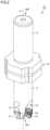
- FIG. 1 is a schematic perspective view showing the structure of a rotating tool. An overview of the structure of the rotating tool will first be described with reference to FIG. 1 .
- the rotating tool 1 of the present embodiment includes a shaft portion 10 and a sensor unit 20.
- the shaft portion 10 extends from a first end 10A to a second end 10B along a rotation axis A.
- the sensor unit 20 is disposed to surround a portion in a longitudinal direction of the shaft portion 10.
- the shaft portion 10 has a plurality of (here, four) recesses 13 formed at equal intervals in a circumferential direction, which are open at the first end 10A and at an outer peripheral surface thereof. Wall surfaces defining the recesses 13 have cutting inserts 91 as cutting edges attached thereto.
- the cutting inserts 91 are disposed around the rotation axis A of the shaft portion 10. As the rotating tool 1 is rotated around the rotation axis A, the cutting inserts 91 can be brought into contact with a workpiece (not shown) to thereby machine the workpiece.
- the rotating tool 1 is a rotating tool that cuts a workpiece by rotating around the rotation axis A of the shaft portion 10.
- FIG. 2 is a schematic perspective view showing the structure of the shaft portion as viewed from the second end 10B side.
- FIG. 3 is a schematic perspective view showing the structure of the shaft portion as viewed from the first end 10A side.
- FIG. 4 is a schematic plan view showing the structure of the shaft portion as viewed from the first end side in the rotation axis direction.
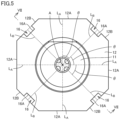
- FIG. 5 is a schematic plan view showing the structure of the shaft portion as viewed from the second end side in the rotation axis direction.
- FIG. 6 is a schematic plan view showing the structure of the shaft portion as viewed in a direction perpendicular to the axis direction.
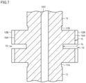
- FIG. 7 is a schematic cross-sectional view showing a cross section along the line VII-VII in FIG. 5 .
- the structure of the shaft portion 10 will be described with reference to FIGS. 2 to 7 .
- the shaft portion 10 includes a body portion 11, and an increased-diameter portion 12 as a first region.
- the body portion 11 has a cylindrical shape.
- the rotation axis A coincides with a central axis of the body portion 11.
- the increased-diameter portion 12 is a portion having a larger diameter than the body portion 11.
- the position of the increased-diameter portion 12 in the longitudinal direction of the body portion 11 is not particularly limited, in the present embodiment, the increased-diameter portion 12 is located at a longitudinally central portion of the body portion 11.
- the increased-diameter portion 12 is located at a region of the shaft portion 10 surrounded by the sensor unit 20.
- the cutting inserts 91 are attached to the wall surfaces defining the recesses 13 of the shaft portion 10, as previously described.
- the cutting inserts 91 are fixed to the shaft portion 10 with screws 92 which are inserted and tightened into screw holes formed in the cutting inserts 91.
- the increased-diameter portion 12 has an octagonal prism shape.
- the increased-diameter portion 12 has an octagonal shape as viewed in a direction along the rotation axis A. More specifically, in a cross section perpendicular to the rotation axis A, the increased-diameter portion 12 has an octagonal shape obtained by removing four isosceles right triangles of the same shape from each of the four corners of a square. The rotation axis A passes through the center of gravity of this octagon. The octagonal shape is consistent in the direction along the rotation axis A.
- the central axis of the body portion 11 coincides with the central axis of the increased-diameter portion 12.
- the central axis of the increased-diameter portion 12 means a straight line passing through the center of gravity of the octagon.
- the octagon is configured with alternately arranged outer peripheral surfaces 12A, corresponding to long sides, and outer peripheral surfaces 12B, corresponding to short sides shorter than the long sides.
- angles ⁇ formed by respective pairs of the perpendicular lines L A and L B of the outer peripheral surfaces 12A and 12B corresponding to the circumferentially adjacent sides of the octagon are equal to each other.
- the angle ⁇ is 45 degrees.
- the octagonal shape is not limited to the above-described shape; the outer peripheral surfaces 12A and the outer peripheral surfaces 12B may have the same length as viewed in the direction along the rotation axis A.
- each outer peripheral surface 12B has a first recess 16 formed to extend in a direction along the rotation axis A.
- a bottom surface 16A defining the first recess 16 is planar.
- the first recess 16 is arranged at a position intersecting the perpendicular line L B .
- the first recess 16 extends through the outer peripheral surface 12B in the direction along the rotation axis A.
- the outer peripheral surfaces 12A and 12B of the increased-diameter portion 12 have a second recess 15 formed to extend in the circumferential direction of the increased-diameter portion 12.
- the second recess 15 is formed to overlap the first recess 16.
- the second recess 15 intersects the first recess 16 (orthogonally).
- the second recess 15 is formed around the entire circumference of the outer peripheral surfaces 12A and 12B of the increased-diameter portion 12. That is, the second recess 15 is formed in a ring shape.
- the second recess 15 has a depth d 2 which is greater than a depth d 1 of the first recess 16.
- a first small-diameter portion 11A having a smaller diameter than other portions is formed.
- a second small-diameter portion 11B having a smaller diameter than other portions is formed.
- the shaft portion 10 has a through hole 10C formed to penetrate through the shaft portion 10 in the direction along the rotation axis A. The through hole 10C extends to include the rotation axis A.
- the sensor unit 20 corresponds to one embodiment of the sensor device of the present disclosure.
- the sensor unit 20 includes a sensor module 80, and a housing 21 that houses the sensor module 80.
- the sensor module 80 includes a plurality of strain sensors 31 as a plurality of first sensors, a board 49 electrically connected to the strain sensors 31, and a wireless communication unit 51 (see FIG. 10 ) electrically connected to the board 49.
- the strain sensors 31 detect a strain as a first physical quantity of the shaft portion 10.
- the wireless communication unit 51 includes an antenna 51A.
- the antenna 51A of the wireless communication unit 51 externally transmits signals containing information on the strain detected by the strain sensors 31.
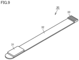
- a strain sensor 31 constitutes a strain sensor component 30.
- the strain sensor component 30 includes the strain sensor 31, and a wire 32 connected to the strain sensor 31 and having a connector 33 at its distal end.
- the wire 32 has a strip shape.
- the strain sensor 31 is disposed near one end of the wire 32.
- the connector 33 is disposed at the other end of the wire 32.
- the board 49 constitutes a board module 40.
- the board 49 includes a board body made of an insulator, such as a resin, and a circuit pattern (not shown) made of a conductor, such as copper, formed on a surface of the board body.
- the board module 40 includes the board 49, the wireless communication unit 51, an acceleration sensor 52 as a second sensor, a socket 53, an AD converter 54, a power supply circuit 55, a battery socket 56, a charging connector 57, and a power switch 58.
- the wireless communication unit 51, the acceleration sensor 52, the socket 53, the AD converter 54, the power supply circuit 55, the battery socket 56, the charging connector 57, and the power switch 58 are disposed on the board 49 and electrically connected to the board 49 (to the circuit pattern on the board 49).
- the acceleration sensor 52 detects an acceleration as a second physical quantity of the shaft portion 10. A plurality of such acceleration sensors 52 are disposed on the board 49.
- the wireless communication unit 51 is electrically connected to the acceleration sensors 52 through the board 49.
- the antenna 51A of the wireless communication unit 51 externally transmits signals containing information on the acceleration of the shaft portion 10 detected by the acceleration sensors 52.
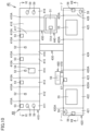
- the board 49 includes a first portion 410, a second portion 420, a first connecting portion 430, a third portion 440, a second connecting portion 450, a fourth portion 460, and a third connecting portion 470.
- the first portion 410 and the second portion 420 each have a strip shape.
- the first portion 410 includes a first portion first zone 411, a first portion second zone 412, a first portion third zone 413, a first portion fourth zone 414, a first portion fifth zone 415, a first portion sixth zone 416, a first portion seventh zone 417, a first portion eighth zone 418, and a first portion ninth zone 419, which are arranged in this order.
- a bendable portion 410A is disposed between each pair of adjacent zones.
- the first portion 410 includes a body portion 49B which is a board having flexibility (a flexible board), and a reinforcing plate 72 which is disposed on a main surface of the body portion 49B (opposite to the main surface on which the circuit pattern is formed) and has a Young's modulus larger than that of the body portion 49B.
- the reinforcing plate 72 is disposed in each of regions corresponding to the first portion first zone 411, the first portion second zone 412, the first portion third zone 413, the first portion fourth zone 414, the first portion fifth zone 415, the first portion sixth zone 416, the first portion seventh zone 417, the first portion eighth zone 418, and the first portion ninth zone 419.
- the reinforcing plate 72 is not disposed in regions corresponding to the bendable portions 410A. As a result, the bendable portions 410A are bendable.
- the first portion first zone 411 and the first portion ninth zone 419 each have at least one through hole 59 (here, a plurality of, specifically two through holes) formed to penetrate through the first portion 410 in a thickness direction thereof.
- the two through holes 59 are arranged side by side in a direction intersecting (orthogonal to) the longitudinal direction of the first portion 410, i.e., in the width direction of the first portion 410.
- the socket 53 is disposed on each of the first portion first zone 411, the first portion third zone 413, the first portion fifth zone 415, and the first portion seventh zone 417. Each socket 53 is disposed at an end in the width direction of the first portion 410.
- the acceleration sensor 52 is disposed on each of the first portion second zone 412, the first portion fourth zone 414, and the first portion sixth zone 416.
- the AD converter 54 is disposed on the first portion fourth zone 414. On the first portion fourth zone 414, the acceleration sensor 52 and the AD converter 54 are arranged side by side in the width direction of the first portion 410.
- the second portion 420 includes a second portion first zone 421, a second portion second zone 422, a second portion third zone 423, a second portion fourth zone 424, a second portion fifth zone 425, and a second portion sixth zone 426, which are arranged in this order.
- a bendable portion 420A is disposed between each pair of adjacent zones.
- the second portion 420 includes a body portion 49B which is a flexible board, and a reinforcing plate 72 which is disposed on a main surface of the body portion 49B (opposite to the main surface on which the circuit pattern is formed) and has a Young's modulus larger than that of the body portion 49B.
- the reinforcing plate 72 is disposed in each of regions corresponding to the second portion first zone 421, the second portion second zone 422, the second portion third zone 423, the second portion fourth zone 424, the second portion fifth zone 425, and the second portion sixth zone 426.
- the reinforcing plate 72 is not disposed in regions corresponding to the bendable portions 420A. As a result, the bendable portions 420A are bendable.
- the second portion third zone 423 and the fourth portion 460 are physically and electrically connected by the third connecting portion 470.
- the power switch 58 is disposed on the fourth portion 460.
- the board 49 is configured such that the portions of the single flexible board requiring rigidity have the reinforcing plate attached thereto, and the portions not having the reinforcing plate attached thereto are bendable.
- the first portion first zone 411, the first portion third zone 413, the first portion fifth zone 415, the first portion seventh zone 417, and the first portion ninth zone 419 each have a length in the longitudinal direction of the first portion 410 corresponding to the length of an outer peripheral surface 12B which is the short side of the above-described octagon when the increased-diameter portion 12 is viewed in the direction along the rotation axis A.
- a strain sensor component 30 is arranged such that the strain sensor 31 straddles the second recess 15 and the strain sensor 31 is housed in the first recess 16 (see, for example, FIGS. 2 , 4 , and 8 ).
- the strain sensor 31 is arranged so as to detect the strain in the direction along the rotation axis A.
- the strain sensor component 30 is installed on each of the four outer peripheral surfaces 12B.
- the strain sensors 31 are disposed on all of the outer peripheral surfaces 12B (outer peripheral surfaces corresponding to the short sides) of the increased-diameter portion 12 whose perpendicular lines L B passing through the rotation axis A form 90 degrees to each other.
- the first portion 410 of the board 49 includes a first main surface 410B, and a second main surface 410C located on the opposite side from the first main surface 410B in the thickness direction.
- the first portion 410 is arranged such that the first main surface 410B faces an outer peripheral surface of the shaft portion 10.
- the wireless communication unit 51, the acceleration sensors 52, the sockets 53, and the AD converter 54 are mounted on the second main surface 410C.
- the first portion 410 is wound around the increased-diameter portion 12 such that the first main surface 410B comes into contact with the outer peripheral surfaces 12A and 12B of the increased-diameter portion 12.
- the first portion first zone 411, the first portion third zone 413, the first portion fifth zone 415, the first portion seventh zone 417, and the first portion ninth zone 419 are disposed on the outer peripheral surfaces 12B, and the first portion second zone 412, the first portion fourth zone 414, the first portion sixth zone 416, and the first portion eighth zone 418 are disposed on the outer peripheral surfaces 12A.
- the first portion 410 bends at the bendable portions 410A.
- the first portion first zone 411 and the first portion ninth zone 419 overlap each other such that the through holes 59 formed therein are aligned. Fixing members (not shown) are installed to pass through the through holes 59, thereby fixing the first portion 410 to the shaft portion 10.
- the first portion 410 is arranged to follow the outer peripheral surfaces 12A and 12B of the increased-diameter portion 12.
- Each socket 53 is disposed on the first portion 410 located on the outer peripheral surface 12B.
- a connector 33 located at one end of the wire 32 connected to the strain sensor 31, is connected to the socket 53. This electrically connects the first portion 410 and the strain sensor 31.
- the wire 32 straddles the first portion 410 in the width direction (direction along the rotation axis A).
- the wire 32 is bent into an arcuate shape. That is, the wire 32 connects the strain sensor 31 and the socket 53 with slack.
- the acceleration sensors 52 are disposed on the outer peripheral surfaces 12A (outer peripheral surfaces corresponding to the long sides) of the increased-diameter portion 12 whose perpendicular lines L A passing through the rotation axis A form 90 degrees to each other.
- the strain sensors 31 and the acceleration sensors 52 are disposed on the outer peripheral surfaces 12A and 12B of the increased-diameter portion 12 corresponding to the different sides of the octagon.
- the second portion 420 of the board 49 includes a third main surface 420B, and a fourth main surface 420C located on the opposite side from the third main surface 420B in the thickness direction.
- the second portion 420 is arranged on an outer periphery side of the first portion 410 in the radial direction of the shaft portion 10 such that the third main surface 420B faces the shaft portion 10 side.
- the first connecting portion 430 which electrically connects the first portion 410 and the second portion 420, is disposed between the first portion 410 and the second portion 420 in the radial direction of the shaft portion 10.
- the housing 21 includes a tubular side wall portion 23 surrounding the shaft portion 10 and extending in the direction along the rotation axis A, a bottom wall portion 22 closing a first opening of the side wall portion 23 in the direction along the rotation axis A, and an upper wall portion 24 closing a second opening of the side wall portion located on the opposite side from the first opening in the direction along the rotation axis A.
- the bottom wall portion 22 is made of a resin.
- the first portion 410 is arranged to extend in a circumferential direction of the shaft portion 10 along the outer peripheral surface of the shaft portion 10.
- the second portion 420 is arranged to extend in a circumferential direction of the side wall portion 23 along an inner peripheral surface of the side wall portion 23. The second portion 420 bends at the bendable portions 420A.
- the power supply circuits 55, the battery sockets 56, the charging connector 57, and the like are disposed on the third main surface 420B of the second portion 420.
- the connecting direction ⁇ of each battery socket 56 is the direction along the rotation axis A.
- the batteries 99 supply power, via the battery sockets 56 and the power supply circuits 55 disposed on the second portion 420, to the wireless communication unit 51, the acceleration sensors 52, the sockets 53, and the AD converter 54 on the first portion 410, which is connected to the second portion 420 by the first connecting portion 430.
- the batteries 99 are charged through the charging connector 57 disposed on the second portion 420.
- the batteries 99 may be primary batteries.
- the third portion 440 as a base member on which the wireless communication unit 51 including the antenna 51A is mounted is disposed between the first portion 410 and the second portion 420 in the radial direction of the shaft portion 10.
- the installation state of the wireless communication unit 51 including the antenna 51A is adjusted with the bending of the second connecting portion 450.
- the wireless communication unit 51 including the antenna 51A is mounted on a mounting surface 440A as a first surface of the third portion 440. That is, in the present embodiment, the base member is the board.
- the fourth portion 460 on which the power switch 58 is mounted, is disposed between the first portion 410 and the second portion 420 in the radial direction of the shaft portion 10.
- the installation state of the power switch 58 can be adjusted with the bending of the third connecting portion 470.
- the power switch 58 is capable of switching the state (ON or OFF) of the power supply from the batteries 99.
- the second fixing member 65 is a component having a flat circular arc shape.
- the housing 21 includes two second fixing members 65.
- Each second fixing member 65 has an inner peripheral surface 65A having a shape corresponding to a part of the flat surface shape of the outer peripheral surface of the increased-diameter portion 12, i.e., a shape corresponding to a part of the octagon.
- the second fixing members 65 have a plurality of screw holes 66 (here, two screw holes for each second fixing member 65) formed to correspond to the screw holes 62 in the upper wall portion 24 of the housing main body 61 and the screw holes 64 in the first fixing member 63.
- the material constituting the second fixing members 65 is, for example, a resin.
- the lid (bottom wall portion) 22 has a disk shape with a through hole 22A at the center.
- the material constituting the lid 22 is, for example, a resin.
- each second fixing member 65 has a shape corresponding to a part of the flat surface shape of the outer peripheral surface of the increased-diameter portion 12 (shape corresponding to a part of the octagon), the housing main body 61 is prevented from rotating circumferentially relative to the shaft portion 10.
- the lid (bottom wall portion) 22 is fixed to the increased-diameter portion 12 by, for example, screws or the like in the state of being in contact with the end surface of the side wall portion 23 and the end surface of the increased-diameter portion 12. In this manner, the housing 21 is fixed to the shaft portion 10 in the state with the sensor module 80 housed therein.
- the first connecting portion 430 is a flexible board. Connecting the first portion 410 and the second portion 420 with the flexible board having flexibility in this manner facilitates proper installation of the first portion 410 and the second portion 420.
- the first portion 410, the second portion 420, and the first connecting portion 430 include a single flexible board that extends over the entirety of the first portion 410, the second portion 420, and the first connecting portion 430. More specifically, the first connecting portion 430, the body portion 49B of the first portion 410, and the body portion 49B of the second portion 420 are composed of a single flexible board. Of the single flexible board, the portions requiring rigidity have the reinforcing plate 72 attached thereto, and the portions not having the reinforcing plate 72 attached thereto are bendable. As a result, a high degree of design freedom is ensured for the board module 40.
- the connecting direction ⁇ of each battery socket 56 is the direction along the rotation axis A. This suppresses falling of the connector from the battery socket 56 due to the centrifugal force resulting from the rotation of the rotating tool 1.
- a plurality of batteries 99 are disposed at equal intervals in the circumferential direction of the shaft portion 10. Arranging the batteries 99 having a large mass in this manner can achieve stable rotation of the rotating tool 1.
- the AD converter 54 is disposed on the second main surface 410C.
- a strain sensor 31 and an acceleration sensor 52 as a first sensor and a second sensor, respectively.
- the acceleration sensor 52 as the second sensor may be omitted.
- the acceleration sensor 52 can be adopted, with the strain sensor 31 being omitted.
- the first sensor may be the acceleration sensor.
- a sensor that detects a physical quantity other than the strain and acceleration for example, a temperature sensor may be adopted in addition to, or in place of one or both of, the strain sensor 31 and the acceleration sensor 52.
- the increased-diameter portion 12 disposed on a region of the shaft portion 10 surrounded by the sensor unit 20, has an octagonal shape as viewed in the direction along the rotation axis A.
- the increased-diameter portion only needs to have the planar shape of a 4n-gon (n is a natural number of 2 or more), which may be, for example, a dodecagon, a hexadecagon, or an icosagon.
- the strain sensor is disposed on each of the outer peripheral surfaces in the set.
- the strain sensors By installing the strain sensors on the first and second outer peripheral surfaces whose perpendicular lines passing through the rotation axis form 90 degrees to each other, it is possible to obtain information on the magnitude and direction of a load acting in a plane perpendicular to the rotation axis. Furthermore, by installing the strain sensor also on the third outer peripheral surface, the effect of the load parallel to the rotation axis can be eliminated, making it possible to more accurately obtain the information on the magnitude and direction of the load acting in the plane perpendicular to the rotation axis.
- first fixing member 63 and the second fixing members 65 are separate.
- first fixing member 63 and the second fixing members 65 may be unitary.
- first fixing member 63 and the second fixing members 65 may be a single member made of a metal.
- the tapered portion 10F is inserted into a recess formed in a main spindle of a machine tool, so that the rotating tool 1 is held by the main spindle of the machine tool.
- the tapered portion 10F, the first protruding portion 10D, and the second protruding portion 10E have their shapes which can be suitably selected to match the chuck mechanism for a tool provided in the main spindle of the machine tool.
- FIG. 21 is a schematic perspective view showing the structure of a rotating tool of Embodiment 3.
- the rotating tool 1 of the present embodiment basically has the same structure, operates in the same manner, and provides the same effects as the rotating tool 1 of Embodiment 1 described with reference to FIGS. 1 to 19 .
- the rotating tool 1 of Embodiment 3 differs from that of Embodiment 1 in that a portion including the sensor unit 20 as the sensor device of the present disclosure and a portion including the first end 10A are separable.
- the external thread portion 19A is screwed into the internal thread portion 19B to couple the external thread portion 19A with the internal thread portion 19B, so that the distal end region 10I and the proximal end region 10H are integrated.
- the rotating tool 1 similar to that of Embodiment 1 is obtained.
- the distal end region 10I and the proximal end region 10H can be separated by releasing the coupling between the external thread portion 19A and the internal thread portion 19B.
- the first direction ⁇ which is the direction perpendicular to the mounting surface 440A of the third portion 440 on which the wireless communication unit 51 including the antenna 51A as a transmitting antenna is mounted, is inclined with respect to both the plane ⁇ (X-Y plane) perpendicular to the rotation axis A and the rotation axis A (Z axis direction). That is, the first direction ⁇ is not parallel to any of the X axis, the Y axis, and the Z axis.
Landscapes
- Engineering & Computer Science (AREA)
- Mechanical Engineering (AREA)
- Physics & Mathematics (AREA)
- General Physics & Mathematics (AREA)
- Milling Processes (AREA)
- Arrangements For Transmission Of Measured Signals (AREA)
- Machine Tool Sensing Apparatuses (AREA)
- Details Of Aerials (AREA)
- Support Of Aerials (AREA)
Abstract
Description
- The present disclosure relates to a rotating tool, a rotating tool system, and a sensor device.
- Techniques for monitoring the state of a cutting tool during machining with the cutting tool by measuring a physical quantity of the cutting tool using a sensor are known (see, for example,
U.S. Patent Application Publication No. 2015/0261207 (Patent Literature 1),Japanese Patent Application Laid-Open No. 2018-54611 Japanese Patent Application Laid-Open No. 2009-285804 WO 2017/002762 (Patent Literature 4),Japanese Patent No. 5988066 Japanese Utility Model Registration No. 3170029 Japanese Patent Application Laid-Open No. 2015-77658 WO 2015/056495 (Patent Literature 8),European Patent Application Publication No. 3292929 (Patent Literature 9), andEuropean Patent Application Publication No. 3292930 (Patent Literature 10)). -
- Patent Literature 1:
U.S. Patent Application Publication No. 2015/0261207 - Patent Literature 2:
Japanese Patent Application Laid-Open No. 2018-54611 - Patent Literature 3:
Japanese Patent Application Laid-Open No. 2009-285804 - Patent Literature 4: International Publication
WO 2017/002762 - Patent Literature 5:
Japanese Patent Application Laid-Open No. 2016-221665 - Patent Literature 6:
Japanese Utility Model Registration No. 3170029 - Patent Literature 7:
Japanese Patent Application Laid-Open No. 2015-77658 - Patent Literature 8: International Publication
WO 2015/056495 - Patent Literature 9:
European Patent Application Publication No. 3292929 - Patent Literature 10:
European Patent Application Publication No. 3292930 - The rotating tool according to the present disclosure is a rotating tool that includes: a shaft portion extending from a first end to a second end along a rotation axis; a sensor unit disposed on the shaft portion; and a cutting edge disposed around the rotation axis of the shaft portion. The sensor unit includes a sensor module, the sensor module including a first sensor that detects a first physical quantity of the shaft portion, a base member, and an antenna that is mounted on a first surface of the base member and externally transmits a signal containing information on the first physical quantity detected by the first sensor. The antenna is a chip antenna or a PCB antenna. In a cross section including the rotation axis, a first direction as a direction perpendicular to the first surface is inclined with respect to a plane perpendicular to the rotation axis and with respect to the rotation axis.
-
- [
FIG. 1] FIG. 1 is a schematic perspective view showing the structure of a rotating tool. - [
FIG. 2] FIG. 2 is a schematic perspective view showing the structure of a shaft portion. - [
FIG. 3] FIG. 3 is a schematic perspective view showing the structure of the shaft portion, as viewed from a different point of view fromFIG. 2 . - [
FIG. 4] FIG. 4 is a schematic plan view showing the structure of the shaft portion as viewed from a first end side in a rotation axis direction. - [
FIG. 5] FIG. 5 is a schematic plan view showing the structure of the shaft portion as viewed from a second end side in the rotation axis direction. - [
FIG. 6] FIG. 6 is a schematic plan view showing the structure of the shaft portion as viewed in a direction perpendicular to the axis direction. - [
FIG. 7] FIG. 7 is a schematic cross-sectional view showing a cross section along the line VII-VII inFIG. 5 . - [
FIG. 8] FIG. 8 is a schematic cross-sectional view showing the structure of a sensor unit and its surroundings. - [
FIG. 9] FIG. 9 is a schematic perspective view showing the structure of a strain sensor component. - [
FIG. 10] FIG. 10 is a schematic plan view showing the structure of a board module. - [
FIG. 11] FIG. 11 is a schematic cross-sectional view showing a cross section along the line XI-XI inFIG. 10 . - [
FIG. 12] FIG. 12 is a schematic cross-sectional view showing a cross section along the line XII-XII inFIG. 10 . - [
FIG. 13] FIG. 13 is a schematic plan view showing a state in which the board module is attached. - [
FIG. 14] FIG. 14 is a schematic cross-sectional view showing a cross section along the line XIV-XIV inFIG. 13 . - [
FIG. 15] FIG. 15 is a schematic cross-sectional view showing a cross section along the line XV-XV inFIG. 13 . - [
FIG. 16] FIG. 16 is a schematic perspective view showing the structure of a housing main body. - [
FIG. 17] FIG. 17 is a schematic perspective view showing the structure of a first fixing member. - [
FIG. 18] FIG. 18 is a schematic perspective view showing the structure of a second fixing member. - [
FIG. 19] FIG. 19 is a schematic perspective view showing the structure of a lid (bottom wall portion). - [
FIG. 20] FIG. 20 is a schematic perspective view showing the structure of a rotating tool of Embodiment 2. - [
FIG. 21] FIG. 21 is a schematic perspective view showing the structure of a rotating tool of Embodiment 3. - [
FIG. 22] FIG. 22 is a schematic perspective view showing the structure of a rotating tool of Embodiment 4. - [
FIG. 23] FIG. 23 is a schematic perspective view showing the rotating tool of Embodiment 4 in a disassembled state. - [
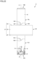
FIG. 24] FIG. 24 is a schematic diagram showing the configuration of a rotating tool system of Embodiment 5. - From the viewpoint of closely monitoring the state of the cutting tool during machining, it is required that signals containing information obtained by a sensor be received in an externally installed receiver while suppressing the loss of the information. One of the objects of the present disclosure is to provide a rotating tool, a rotating tool system, and a sensor device that facilitate the reception of signals containing information obtained by a sensor in an externally installed receiver while suppressing the loss of the information.
- According to the rotating tool, the rotating tool system, and the sensor device of the present disclosure, it is possible to provide a rotating tool, a rotating tool system, and a sensor device that facilitate the reception of signals containing information obtained by a sensor in an externally installed receiver while suppressing the loss of the information.
- Embodiments of the present disclosure will first be listed and described. The rotating tool of the present disclosure is a rotating tool that includes: a shaft portion extending from a first end to a second end along a rotation axis; a sensor unit disposed on the shaft portion; and a cutting edge disposed around the rotation axis of the shaft portion. The sensor unit includes a sensor module, the sensor module including a first sensor that detects a first physical quantity of the shaft portion, a base member, and an antenna that is mounted on a first surface of the base member and externally transmits a signal containing information on the first physical quantity detected by the first sensor. The antenna is a chip antenna or a PCB antenna. In a cross section including the rotation axis, a first direction as a direction perpendicular to the first surface is inclined with respect to a plane perpendicular to the rotation axis and with respect to the rotation axis.
- In a rotating tool that cuts a workpiece by rotating around the rotation axis of a shaft portion, when a signal containing information obtained by a sensor is received in an externally installed receiver, the information tends to be lost to a large extent. According to studies conducted by the present inventors, this is due to the following reasons. A chip antenna or a PCB antenna (transmitting antenna) included in the rotating tool is mounted on a mounting surface (first surface) of a base member included in the rotating tool. At this time, from the viewpoint of ease of installation of a communication module including the transmitting antenna, a direction perpendicular to the mounting surface tends to be parallel or perpendicular to a plane perpendicular to the rotation axis of the shaft portion. In addition, from the viewpoint of ease of installation of a receiver including a linear antenna (receiving antenna), such as a monopole antenna or a dipole antenna, that receives the signal transmitted, the receiver tends to be installed such that a longitudinal direction of the linear antenna included therein is parallel or perpendicular to the plane perpendicular to the rotation axis of the shaft portion. Then, with the rotation of the rotating tool around the rotation axis, a moment may occur when the direction perpendicular to the mounting surface for the transmitting antenna becomes orthogonal to the longitudinal direction of the receiving antenna. At such a moment, the electric field intensity of a polarized radio wave in a direction easier for the receiving antenna to receive becomes extremely weak in the transmitted signal. This results in a significant loss of information in the information received at the receiving antenna, as compared to the information contained in the transmitted signal.
- In the rotating tool of the present disclosure, the first direction, which is the direction perpendicular to the first surface of the base member on which the transmitting antenna is mounted, is inclined with respect to both the plane perpendicular to the rotation axis and the rotation axis. This can avoid the occurrence of a moment at which the electric field intensity of a polarized radio wave in a direction easier for the receiving antenna to receive becomes extremely weak. As a result, it becomes easier for an externally installed receiver to receive signals containing information obtained by a sensor, while suppressing the loss of the information.
- In the above rotating tool, an angle formed by the plane perpendicular to the rotation axis and the first direction may be not less than 5 degrees and not more than 85 degrees. This configuration can further suppress the loss of the information obtained by the sensor. As used herein, the angle formed by the plane perpendicular to the rotation axis and the first direction means an angle that forms the acute of the angles formed by the plane perpendicular to the rotation axis and the first direction.
- In the above rotating tool, the angle formed by the plane perpendicular to the rotation axis and the first direction may be not less than 15 degrees and not more than 75 degrees. This configuration can even further suppress the loss of the information obtained by the sensor.
- In the above rotating tool, the angle formed by the plane perpendicular to the rotation axis and the first direction may be not less than 20 degrees and not more than 70 degrees. This configuration can even further suppress the loss of the information obtained by the sensor.
- In the above rotating tool, the base member may be a board. This configuration facilitates the installation of the antenna (transmitting antenna), which is a chip antenna or a PCB antenna.
- In the above rotating tool, the first sensor may be a strain sensor. This configuration makes it possible to obtain information on the strain, which is important for monitoring the state of the rotating tool.
- In the above rotating tool, the first sensor, which is the strain sensor, may be arranged to detect a strain in a direction along the rotation axis. This configuration makes it possible to obtain information on the strain in the direction along the rotation axis, which is important for monitoring the state of the rotating tool.
- In the above rotating tool, the sensor unit may further include a housing that houses the sensor module. The housing may include a tubular side wall portion surrounding the shaft portion and extending in a direction along the rotation axis, a bottom wall portion closing a first opening of the side wall portion in the direction along the rotation axis, and an upper wall portion closing a second opening of the side wall portion located on an opposite side from the first opening in the direction along the rotation axis. At least one of the bottom wall portion and the upper wall portion may be at least partially made of a resin.
- Forming a part of the housing with a resin facilitates the transmission of signals from the antenna to the outside. In the housing, the presence of a portion formed of a resin in at least one of the bottom and upper wall portions, which have little effect on rigidity, can suppress the reduction in rigidity of the housing.
- A rotating tool system of the present disclosure includes: the rotating tool of the present disclosure described above; and a receiver including a linear antenna that receives the signal containing the information on the first physical quantity transmitted from the antenna (transmitting antenna) described above.
- The rotating tool system of the present disclosure, by including the rotating tool of the present disclosure, facilitates the reception of signals containing information obtained by a sensor in the receiver, while suppressing the loss of the information.
- A sensor device in a first aspect of the present disclosure is a sensor device capable of configuring a sensor unit of a rotating tool, the rotating tool including a shaft portion extending from a first end to a second end along a rotation axis, the sensor unit disposed on the shaft portion, and a cutting edge disposed around the rotation axis of the shaft portion. The sensor device includes a sensor module, the sensor module including a first sensor that detects a first physical quantity of the shaft portion, a base member, and an antenna that is mounted on a first surface of the base member and externally transmits a signal containing information on the first physical quantity detected by the first sensor. The antenna is a chip antenna or a PCB antenna. In a cross section including the rotation axis, a first direction as a direction perpendicular to the first surface is inclined with respect to a plane perpendicular to the rotation axis and with respect to the rotation axis.
- A sensor device in a second aspect of the present disclosure is a sensor device that includes a shaft region extending along a rotation axis, a sensor unit disposed on the shaft region, and a connecting portion formed at an end of the shaft region in a direction along the rotation axis and allowing a machining unit having a cutting edge to be connected thereto. The sensor unit includes a sensor module, the sensor module including a first sensor that detects a first physical quantity of the shaft region, a base member, and an antenna that is mounted on a first surface of the base member and externally transmits a signal containing information on the first physical quantity detected by the first sensor. The antenna is a chip antenna or a PCB antenna. In a cross section including the rotation axis, a first direction as a direction perpendicular to the first surface is inclined with respect to a plane perpendicular to the rotation axis and with respect to the rotation axis.
- In the sensor devices of the present disclosure, the first direction, which is the direction perpendicular to the first surface of the base member on which the transmitting antenna is mounted, is inclined with respect to both the plane perpendicular to the rotation axis and the rotation axis. This can avoid the occurrence of a moment at which the electric field intensity of a polarized radio wave in a direction easier for the receiving antenna to receive becomes extremely weak. As a result, it becomes easier for an externally installed receiver to receive signals containing information obtained by a sensor, while suppressing the loss of the information.
- Embodiments of the rotating tool according to the present disclosure will be described below with reference to the drawings. In the drawings referenced below, the same or corresponding portions are denoted by the same reference numerals and the description thereof will not be repeated.
-
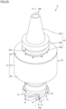
FIG. 1 is a schematic perspective view showing the structure of a rotating tool. An overview of the structure of the rotating tool will first be described with reference toFIG. 1 . Therotating tool 1 of the present embodiment includes ashaft portion 10 and asensor unit 20. Theshaft portion 10 extends from afirst end 10A to asecond end 10B along a rotation axis A. Thesensor unit 20 is disposed to surround a portion in a longitudinal direction of theshaft portion 10. Theshaft portion 10 has a plurality of (here, four) recesses 13 formed at equal intervals in a circumferential direction, which are open at thefirst end 10A and at an outer peripheral surface thereof. Wall surfaces defining therecesses 13 have cuttinginserts 91 as cutting edges attached thereto. The cutting inserts 91 are disposed around the rotation axis A of theshaft portion 10. As therotating tool 1 is rotated around the rotation axis A, the cutting inserts 91 can be brought into contact with a workpiece (not shown) to thereby machine the workpiece. In other words, therotating tool 1 is a rotating tool that cuts a workpiece by rotating around the rotation axis A of theshaft portion 10. - Each component of the rotating tool will now be described in detail.
FIG. 2 is a schematic perspective view showing the structure of the shaft portion as viewed from thesecond end 10B side.FIG. 3 is a schematic perspective view showing the structure of the shaft portion as viewed from thefirst end 10A side.FIG. 4 is a schematic plan view showing the structure of the shaft portion as viewed from the first end side in the rotation axis direction.FIG. 5 is a schematic plan view showing the structure of the shaft portion as viewed from the second end side in the rotation axis direction.FIG. 6 is a schematic plan view showing the structure of the shaft portion as viewed in a direction perpendicular to the axis direction.FIG. 7 is a schematic cross-sectional view showing a cross section along the line VII-VII inFIG. 5 . The structure of theshaft portion 10 will be described with reference toFIGS. 2 to 7 . - Referring to
FIGS. 2 and3 , theshaft portion 10 includes abody portion 11, and an increased-diameter portion 12 as a first region. Thebody portion 11 has a cylindrical shape. The rotation axis A coincides with a central axis of thebody portion 11. The increased-diameter portion 12 is a portion having a larger diameter than thebody portion 11. Although the position of the increased-diameter portion 12 in the longitudinal direction of thebody portion 11 is not particularly limited, in the present embodiment, the increased-diameter portion 12 is located at a longitudinally central portion of thebody portion 11. The increased-diameter portion 12 is located at a region of theshaft portion 10 surrounded by thesensor unit 20. - Referring to
FIGS. 2 to 4 , the cutting inserts 91 are attached to the wall surfaces defining therecesses 13 of theshaft portion 10, as previously described. The cutting inserts 91 are fixed to theshaft portion 10 withscrews 92 which are inserted and tightened into screw holes formed in the cutting inserts 91. - Referring to
FIGS. 2 to 6 , the increased-diameter portion 12 has an octagonal prism shape. Referring toFIGS. 4 and5 , the increased-diameter portion 12 has an octagonal shape as viewed in a direction along the rotation axis A. More specifically, in a cross section perpendicular to the rotation axis A, the increased-diameter portion 12 has an octagonal shape obtained by removing four isosceles right triangles of the same shape from each of the four corners of a square. The rotation axis A passes through the center of gravity of this octagon. The octagonal shape is consistent in the direction along the rotation axis A. The central axis of thebody portion 11 coincides with the central axis of the increased-diameter portion 12. Here, the central axis of the increased-diameter portion 12 means a straight line passing through the center of gravity of the octagon. - Referring to
FIGS. 4 and5 , as viewed in the direction along the rotation axis A, the octagon is configured with alternately arranged outerperipheral surfaces 12A, corresponding to long sides, and outerperipheral surfaces 12B, corresponding to short sides shorter than the long sides. Among perpendicular lines LA and LB passing through the rotation axis A of the outerperipheral surfaces diameter portion 12, angles θ formed by respective pairs of the perpendicular lines LA and LB of the outerperipheral surfaces peripheral surfaces 12A and the outerperipheral surfaces 12B may have the same length as viewed in the direction along the rotation axis A. - Referring to
FIGS. 2 to 6 , each outerperipheral surface 12B has afirst recess 16 formed to extend in a direction along the rotation axis A. Abottom surface 16A defining thefirst recess 16 is planar. Thefirst recess 16 is arranged at a position intersecting the perpendicular line LB. Thefirst recess 16 extends through the outerperipheral surface 12B in the direction along the rotation axis A. The outerperipheral surfaces diameter portion 12 have asecond recess 15 formed to extend in the circumferential direction of the increased-diameter portion 12. Thesecond recess 15 is formed to overlap thefirst recess 16. Thesecond recess 15 intersects the first recess 16 (orthogonally). Thesecond recess 15 is formed around the entire circumference of the outerperipheral surfaces diameter portion 12. That is, thesecond recess 15 is formed in a ring shape. - Referring to
FIGS. 6 and7 , thesecond recess 15 has a depth d2 which is greater than a depth d1 of thefirst recess 16. At a boundary between the increased-diameter portion 12 and thefirst end 10A side of thebody portion 11, a first small-diameter portion 11A having a smaller diameter than other portions is formed. At a boundary between the increased-diameter portion 12 and thesecond end 10B side of thebody portion 11, a second small-diameter portion 11B having a smaller diameter than other portions is formed. Theshaft portion 10 has a through hole 10C formed to penetrate through theshaft portion 10 in the direction along the rotation axis A. The through hole 10C extends to include the rotation axis A. - The structure of the
sensor unit 20 will now be described with reference toFIGS. 8 to 19 . Thesensor unit 20 corresponds to one embodiment of the sensor device of the present disclosure. Referring toFIGS. 8 and10 , thesensor unit 20 includes asensor module 80, and ahousing 21 that houses thesensor module 80. Thesensor module 80 includes a plurality ofstrain sensors 31 as a plurality of first sensors, aboard 49 electrically connected to thestrain sensors 31, and a wireless communication unit 51 (seeFIG. 10 ) electrically connected to theboard 49. Thestrain sensors 31 detect a strain as a first physical quantity of theshaft portion 10. Thewireless communication unit 51 includes anantenna 51A. Theantenna 51A of thewireless communication unit 51 externally transmits signals containing information on the strain detected by thestrain sensors 31. - Referring to
FIG. 9 , astrain sensor 31 constitutes astrain sensor component 30. Thestrain sensor component 30 includes thestrain sensor 31, and awire 32 connected to thestrain sensor 31 and having aconnector 33 at its distal end. Thewire 32 has a strip shape. Thestrain sensor 31 is disposed near one end of thewire 32. Theconnector 33 is disposed at the other end of thewire 32. - Referring to
FIGS. 10 to 12 , theboard 49 constitutes aboard module 40. Theboard 49 includes a board body made of an insulator, such as a resin, and a circuit pattern (not shown) made of a conductor, such as copper, formed on a surface of the board body. - Referring to
FIG. 10 , theboard module 40 includes theboard 49, thewireless communication unit 51, anacceleration sensor 52 as a second sensor, asocket 53, anAD converter 54, apower supply circuit 55, abattery socket 56, a chargingconnector 57, and apower switch 58. Thewireless communication unit 51, theacceleration sensor 52, thesocket 53, theAD converter 54, thepower supply circuit 55, thebattery socket 56, the chargingconnector 57, and thepower switch 58 are disposed on theboard 49 and electrically connected to the board 49 (to the circuit pattern on the board 49). Theacceleration sensor 52 detects an acceleration as a second physical quantity of theshaft portion 10. A plurality ofsuch acceleration sensors 52 are disposed on theboard 49. Thewireless communication unit 51 is electrically connected to theacceleration sensors 52 through theboard 49. Theantenna 51A of thewireless communication unit 51 externally transmits signals containing information on the acceleration of theshaft portion 10 detected by theacceleration sensors 52. - The
board 49 includes afirst portion 410, asecond portion 420, a first connectingportion 430, athird portion 440, a second connectingportion 450, afourth portion 460, and a third connectingportion 470. Thefirst portion 410 and thesecond portion 420 each have a strip shape. Referring toFIGS. 10 and11 , thefirst portion 410 includes a first portionfirst zone 411, a firstportion second zone 412, a first portionthird zone 413, a first portionfourth zone 414, a first portionfifth zone 415, a firstportion sixth zone 416, a first portionseventh zone 417, a first portion eighthzone 418, and a firstportion ninth zone 419, which are arranged in this order. Abendable portion 410A is disposed between each pair of adjacent zones. - Referring to
FIG. 11 , thefirst portion 410 includes abody portion 49B which is a board having flexibility (a flexible board), and a reinforcingplate 72 which is disposed on a main surface of thebody portion 49B (opposite to the main surface on which the circuit pattern is formed) and has a Young's modulus larger than that of thebody portion 49B. The reinforcingplate 72 is disposed in each of regions corresponding to the first portionfirst zone 411, the firstportion second zone 412, the first portionthird zone 413, the first portionfourth zone 414, the first portionfifth zone 415, the firstportion sixth zone 416, the first portionseventh zone 417, the first portion eighthzone 418, and the firstportion ninth zone 419. The reinforcingplate 72 is not disposed in regions corresponding to thebendable portions 410A. As a result, thebendable portions 410A are bendable. - Referring to
FIGS. 10 and11 , the first portionfirst zone 411 and the firstportion ninth zone 419 each have at least one through hole 59 (here, a plurality of, specifically two through holes) formed to penetrate through thefirst portion 410 in a thickness direction thereof. The two throughholes 59 are arranged side by side in a direction intersecting (orthogonal to) the longitudinal direction of thefirst portion 410, i.e., in the width direction of thefirst portion 410. Thesocket 53 is disposed on each of the first portionfirst zone 411, the first portionthird zone 413, the first portionfifth zone 415, and the first portionseventh zone 417. Eachsocket 53 is disposed at an end in the width direction of thefirst portion 410. Theacceleration sensor 52 is disposed on each of the firstportion second zone 412, the first portionfourth zone 414, and the firstportion sixth zone 416. TheAD converter 54 is disposed on the first portionfourth zone 414. On the first portionfourth zone 414, theacceleration sensor 52 and theAD converter 54 are arranged side by side in the width direction of thefirst portion 410. - Referring to
FIGS. 10 and12 , thesecond portion 420 includes a second portionfirst zone 421, a secondportion second zone 422, a second portionthird zone 423, a second portionfourth zone 424, a second portionfifth zone 425, and a secondportion sixth zone 426, which are arranged in this order. Abendable portion 420A is disposed between each pair of adjacent zones. - Referring to
FIG. 12 , thesecond portion 420 includes abody portion 49B which is a flexible board, and a reinforcingplate 72 which is disposed on a main surface of thebody portion 49B (opposite to the main surface on which the circuit pattern is formed) and has a Young's modulus larger than that of thebody portion 49B. The reinforcingplate 72 is disposed in each of regions corresponding to the second portionfirst zone 421, the secondportion second zone 422, the second portionthird zone 423, the second portionfourth zone 424, the second portionfifth zone 425, and the secondportion sixth zone 426. The reinforcingplate 72 is not disposed in regions corresponding to thebendable portions 420A. As a result, thebendable portions 420A are bendable. - Referring to
FIGS. 10 and12 , the second portionfirst zone 421 and the secondportion sixth zone 426 each have a throughhole 59 formed to penetrate through thesecond portion 420 in a thickness direction thereof. Thebattery socket 56 is disposed on each of the second portionfirst zone 421 and the secondportion sixth zone 426. Eachbattery socket 56 is disposed at the central portion in the width direction of thesecond portion 420. A connecting direction of the battery socket 56 (connecting direction γ for a connector to be connected to the battery socket 56) is a direction along the width direction of thesecond portion 420. When theboard module 40 is housed in thehousing 21, as will be described later, the connecting direction γ of thebattery socket 56 becomes the direction along the rotation axis A. Thepower supply circuit 55 is disposed on each of the secondportion second zone 422 and the second portionfifth zone 425. The chargingconnector 57 is disposed on the second portionthird zone 423. - The first
portion sixth zone 416 and the second portionfourth zone 424 are physically and electrically connected by the first connectingportion 430 having a strip shape. The first connectingportion 430, thebody portion 49B of thefirst portion 410, and thebody portion 49B of thesecond portion 420 are composed of a single flexible board. That is, thefirst portion 410, thesecond portion 420, and the first connectingportion 430 include a single flexible board that extends over the entirety of thefirst portion 410, thesecond portion 420, and the first connectingportion 430. The first portion eighthzone 418 and thethird portion 440 are physically and electrically connected by the second connectingportion 450. Thewireless communication unit 51 including theantenna 51A is disposed on thethird portion 440. The second portionthird zone 423 and thefourth portion 460 are physically and electrically connected by the third connectingportion 470. Thepower switch 58 is disposed on thefourth portion 460. Theboard 49 is configured such that the portions of the single flexible board requiring rigidity have the reinforcing plate attached thereto, and the portions not having the reinforcing plate attached thereto are bendable. - Referring to
FIGS. 10 and5 , the first portionfirst zone 411, the first portionthird zone 413, the first portionfifth zone 415, the first portionseventh zone 417, and the firstportion ninth zone 419 each have a length in the longitudinal direction of thefirst portion 410 corresponding to the length of an outerperipheral surface 12B which is the short side of the above-described octagon when the increased-diameter portion 12 is viewed in the direction along the rotation axis A. The firstportion second zone 412, the first portionfourth zone 414, the firstportion sixth zone 416, and the first portion eighthzone 418 each have a length in the longitudinal direction of thefirst portion 410 corresponding to the length of an outerperipheral surface 12A which is the long side of the octagon when the increased-diameter portion 12 is viewed in the direction along the rotation axis A. - The installation of the
strain sensor components 30 and theboard module 40 with respect to theshaft portion 10 will now be described. Astrain sensor component 30 is arranged such that thestrain sensor 31 straddles thesecond recess 15 and thestrain sensor 31 is housed in the first recess 16 (see, for example,FIGS. 2 ,4 , and8 ). In other words, thestrain sensor 31 is arranged so as to detect the strain in the direction along the rotation axis A. Thestrain sensor component 30 is installed on each of the four outerperipheral surfaces 12B. As a result, as viewed in the direction along the rotation axis A, among the outer peripheral surfaces of the increased-diameter portion 12 corresponding to the respective sides of the octagon, thestrain sensors 31 are disposed on all of the outerperipheral surfaces 12B (outer peripheral surfaces corresponding to the short sides) of the increased-diameter portion 12 whose perpendicular lines LB passing through the rotation axis A form 90 degrees to each other. - Referring to
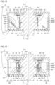
FIGS. 13 to 15 , thefirst portion 410 of theboard 49 includes a firstmain surface 410B, and a secondmain surface 410C located on the opposite side from the firstmain surface 410B in the thickness direction. Thefirst portion 410 is arranged such that the firstmain surface 410B faces an outer peripheral surface of theshaft portion 10. Thewireless communication unit 51, theacceleration sensors 52, thesockets 53, and theAD converter 54 are mounted on the secondmain surface 410C. Thefirst portion 410 is wound around the increased-diameter portion 12 such that the firstmain surface 410B comes into contact with the outerperipheral surfaces diameter portion 12. At this time, the first portionfirst zone 411, the first portionthird zone 413, the first portionfifth zone 415, the first portionseventh zone 417, and the firstportion ninth zone 419 are disposed on the outerperipheral surfaces 12B, and the firstportion second zone 412, the first portionfourth zone 414, the firstportion sixth zone 416, and the first portion eighthzone 418 are disposed on the outerperipheral surfaces 12A. Thefirst portion 410 bends at thebendable portions 410A. The first portionfirst zone 411 and the firstportion ninth zone 419 overlap each other such that the throughholes 59 formed therein are aligned. Fixing members (not shown) are installed to pass through the throughholes 59, thereby fixing thefirst portion 410 to theshaft portion 10. - As a result, as viewed in the direction along the rotation axis A, the
first portion 410 is arranged to follow the outerperipheral surfaces diameter portion 12. Eachsocket 53 is disposed on thefirst portion 410 located on the outerperipheral surface 12B. Aconnector 33, located at one end of thewire 32 connected to thestrain sensor 31, is connected to thesocket 53. This electrically connects thefirst portion 410 and thestrain sensor 31. As shown inFIG. 8 , thewire 32 straddles thefirst portion 410 in the width direction (direction along the rotation axis A). Thewire 32 is bent into an arcuate shape. That is, thewire 32 connects thestrain sensor 31 and thesocket 53 with slack. As viewed in the direction along the rotation axis A, among the outer peripheral surfaces of the increased-diameter portion 12 corresponding to the respective sides of the octagon, theacceleration sensors 52 are disposed on the outerperipheral surfaces 12A (outer peripheral surfaces corresponding to the long sides) of the increased-diameter portion 12 whose perpendicular lines LA passing through the rotation axis A form 90 degrees to each other. Thestrain sensors 31 and theacceleration sensors 52 are disposed on the outerperipheral surfaces diameter portion 12 corresponding to the different sides of the octagon. - Referring to
FIGS. 14 and 15 , thesecond portion 420 of theboard 49 includes a thirdmain surface 420B, and a fourthmain surface 420C located on the opposite side from the thirdmain surface 420B in the thickness direction. Thesecond portion 420 is arranged on an outer periphery side of thefirst portion 410 in the radial direction of theshaft portion 10 such that the thirdmain surface 420B faces theshaft portion 10 side. The first connectingportion 430, which electrically connects thefirst portion 410 and thesecond portion 420, is disposed between thefirst portion 410 and thesecond portion 420 in the radial direction of theshaft portion 10. - The
housing 21 includes a tubularside wall portion 23 surrounding theshaft portion 10 and extending in the direction along the rotation axis A, abottom wall portion 22 closing a first opening of theside wall portion 23 in the direction along the rotation axis A, and anupper wall portion 24 closing a second opening of the side wall portion located on the opposite side from the first opening in the direction along the rotation axis A. Thebottom wall portion 22 is made of a resin. Thefirst portion 410 is arranged to extend in a circumferential direction of theshaft portion 10 along the outer peripheral surface of theshaft portion 10. Thesecond portion 420 is arranged to extend in a circumferential direction of theside wall portion 23 along an inner peripheral surface of theside wall portion 23. Thesecond portion 420 bends at thebendable portions 420A. Thepower supply circuits 55, thebattery sockets 56, the chargingconnector 57, and the like are disposed on the thirdmain surface 420B of thesecond portion 420. At this time, the connecting direction γ of eachbattery socket 56 is the direction along the rotation axis A. - Referring to
FIGS. 13 and15 , thesensor module 80 includes abattery 99. In the present embodiment, thesensor module 80 includes a plurality of (specifically, two)batteries 99. Thebatteries 99 are disposed between thefirst portion 410 and thesecond portion 420 in the radial direction of theshaft portion 10. The plurality ofbatteries 99 are disposed at equal intervals in the circumferential direction of theshaft portion 10. As viewed in the direction along the rotation axis A, the plurality ofbatteries 99 are disposed symmetrically with respect to the rotation axis A. Thebatteries 99 are rechargeable batteries, i.e., secondary batteries. Thebatteries 99 supply power, via thebattery sockets 56 and thepower supply circuits 55 disposed on thesecond portion 420, to thewireless communication unit 51, theacceleration sensors 52, thesockets 53, and theAD converter 54 on thefirst portion 410, which is connected to thesecond portion 420 by the first connectingportion 430. Thebatteries 99 are charged through the chargingconnector 57 disposed on thesecond portion 420. Thebatteries 99 may be primary batteries. - The
third portion 440 as a base member on which thewireless communication unit 51 including theantenna 51A is mounted is disposed between thefirst portion 410 and thesecond portion 420 in the radial direction of theshaft portion 10. Here, the installation state of thewireless communication unit 51 including theantenna 51A is adjusted with the bending of the second connectingportion 450. Specifically, referring toFIG. 14 , thewireless communication unit 51 including theantenna 51A is mounted on a mountingsurface 440A as a first surface of thethird portion 440. That is, in the present embodiment, the base member is the board. The base member of the present disclosure is not limited to the board; a support member of any shape having a first surface (mounting surface) on which theantenna 51A (thewireless communication unit 51 including theantenna 51A) is mounted can be adopted as the base member. Theantenna 51A is a chip antenna or a PCB antenna. Theantenna 51A is a transmitting antenna that externally transmits information on the strain as the first physical quantity detected by thestrain sensors 31 as the first sensors, and information on the acceleration as the second physical quantity detected by theacceleration sensors 52 as the second sensors. In a cross section including the rotation axis A (cross section shown inFIG. 14 ), a first direction α, which is a direction perpendicular to the mountingsurface 440A, is inclined with respect to a plane β perpendicular to the rotation axis A and with respect to the rotation axis A. The angle formed by the plane β perpendicular to the rotation axis A and the first direction α is preferably not less than 5 degrees and not more than 85 degrees, not less than 15 degrees and not more than 75 degrees, and further, not less than 20 degrees and not more than 70 degrees. The angle formed by the plane β perpendicular to the rotation axis A and the first direction α can be set to, for example, not less than 30 degrees and not more than 45 degrees. - The
fourth portion 460, on which thepower switch 58 is mounted, is disposed between thefirst portion 410 and thesecond portion 420 in the radial direction of theshaft portion 10. The installation state of thepower switch 58 can be adjusted with the bending of the third connectingportion 470. Thepower switch 58 is capable of switching the state (ON or OFF) of the power supply from thebatteries 99. - The installation of the
housing 21 with respect to theshaft portion 10 will now be described. Referring toFIG. 8 andFIGS. 13 to 19 , thehousing 21 includes a housingmain body 61, a first fixingmember 63, a second fixingmember 65, and alid 22. The housingmain body 61, as shown inFIG. 16 , includes the disk-shapedupper wall portion 24 having a throughhole 61A at the center, and theside wall portion 23 of a cylindrical shape rising from an outer peripheral surface of theupper wall portion 24. Theupper wall portion 24 has a plurality of (here, eight) screw holes 62 formed at equal intervals in a circumferential direction to penetrate through theupper wall portion 24 in a thickness direction thereof. The material constituting the housingmain body 61 is, for example, a metal. Examples of the metal that can be adopted include an aluminum alloy and an iron alloy (steel such as stainless steel). - Referring to
FIG. 17 , the first fixingmember 63 has an annular flat plate shape divided into two. The first fixingmember 63 has a plurality of screw holes 64 (here, a total of eight screw holes in the first fixingmember 63 divided into two) formed at equal intervals in a circumferential direction so as to correspond to the screw holes 62 in theupper wall portion 24 of the housingmain body 61. The first fixingmember 63 has an innerperipheral surface 63A having a shape corresponding to the second small-diameter portion 11B of theshaft portion 10. In the state in which the two halves of the first fixingmember 63 are combined into a ring shape, the innerperipheral surface 63A has a diameter equal to or slightly larger than the diameter of the first small-diameter portion 11A. The material constituting the first fixingmember 63 is, for example, a metal. Examples of the metal that can be adopted include an aluminum alloy and an iron alloy (steel such as stainless steel). - Referring to
FIG. 18 , the second fixingmember 65 is a component having a flat circular arc shape. In the present embodiment, thehousing 21 includes twosecond fixing members 65. Each second fixingmember 65 has an innerperipheral surface 65A having a shape corresponding to a part of the flat surface shape of the outer peripheral surface of the increased-diameter portion 12, i.e., a shape corresponding to a part of the octagon. Thesecond fixing members 65 have a plurality of screw holes 66 (here, two screw holes for each second fixing member 65) formed to correspond to the screw holes 62 in theupper wall portion 24 of the housingmain body 61 and the screw holes 64 in the first fixingmember 63. The material constituting thesecond fixing members 65 is, for example, a resin. - Referring to
FIG. 19 , the lid (bottom wall portion) 22 has a disk shape with a throughhole 22A at the center. The material constituting thelid 22 is, for example, a resin. - Referring to
FIG. 8 , the housingmain body 61 is arranged such that thebody portion 11 of theshaft portion 10 passes through the throughhole 61A in theupper wall portion 24 of the housingmain body 61. The first fixingmember 63, while being positioned in contact with theupper wall portion 24, is fitted into the second small-diameter portion 11B of thebody portion 11 such that its innerperipheral surface 63A contacts the wall surface of the second small-diameter portion 11B. Thesecond fixing members 65, while being positioned in contact with the first fixingmember 63, are arranged such that their innerperipheral surfaces 65A contact the outerperipheral surfaces diameter portion 12. - The housing
main body 61, the first fixingmember 63, and thesecond fixing members 65 are then fixed to each other with screws which pass through the screw holes 64 in thesecond fixing members 65 and the screw holes 64 in the first fixingmember 63 to reach the screw holes 62 in theupper wall portion 24. At this time, since the inside diameter of the first fixingmember 63 corresponds to the outside diameter of the second small-diameter portion 11B, the central axis of the housingmain body 61 coincides with the rotation axis A. Furthermore, since the innerperipheral surface 65A of each second fixingmember 65 has a shape corresponding to a part of the flat surface shape of the outer peripheral surface of the increased-diameter portion 12 (shape corresponding to a part of the octagon), the housingmain body 61 is prevented from rotating circumferentially relative to theshaft portion 10. The lid (bottom wall portion) 22 is fixed to the increased-diameter portion 12 by, for example, screws or the like in the state of being in contact with the end surface of theside wall portion 23 and the end surface of the increased-diameter portion 12. In this manner, thehousing 21 is fixed to theshaft portion 10 in the state with thesensor module 80 housed therein. - During operation of the
rotating tool 1, therotating tool 1 rotates around the rotation axis A. A workpiece is machined with the cutting inserts 91 coming into contact with the workpiece. At this time, the strain and the acceleration of theshaft portion 10 are detected by thestrain sensors 31 and theacceleration sensors 52, respectively. The pieces of information on the strain and acceleration, which are analog signals, are converted to digital signals in theAD converter 54 and then transmitted to the outside by theantenna 51A in thewireless communication unit 51. Thewireless communication unit 51 and theAD converter 54 operate with power supplied from thebatteries 99 through thebattery sockets 56 and thepower supply circuits 55. Since the lid (bottom wall portion) 22 of thehousing 21 is made of a resin, thewireless communication unit 51 can transmit signals to the outside through the lid (bottom wall portion) 22. The signals are received and analyzed by an externally installed receiver to monitor the state of theshaft portion 10. - In the
rotating tool 1 of the present embodiment, the first direction α, which is the direction perpendicular to the mountingsurface 440A of thethird portion 440 on which thewireless communication unit 51 including theantenna 51A as a transmitting antenna is mounted, is inclined with respect to both the plane β perpendicular to the rotation axis A and the rotation axis A. This can avoid the occurrence of a moment at which the electric field intensity of a polarized radio wave in a direction easier for a receiving antenna to receive becomes extremely weak. As a result, therotating tool 1 of the present embodiment is a rotating tool which makes it easy for an externally installed receiver to receive signals containing information obtained bystrain sensors 31 and the like, while suppressing the loss of the information. - In the
rotating tool 1 of the present embodiment, thebottom wall portion 22 made of a resin is adopted. This facilitates the transmission of signals from the antenna to the outside, while suppressing the reduction of the rigidity of thehousing 21. It should be noted that theupper wall portion 24 may be made of a resin, or thebottom wall portion 22 and theupper wall portion 24 may be only partially made of a resin. - In the
rotating tool 1 of the present embodiment, thebattery sockets 56, which are components disposed on thesecond portion 420 arranged on the outer periphery side of thefirst portion 410, are disposed on the thirdmain surface 420B, which is the main surface facing theshaft portion 10 side. As a result, falling of thebattery sockets 56 due to the centrifugal force is suppressed. In addition, the power supply circuits and the chargingconnector 57, which are components disposed on thesecond portion 420, are also disposed on the thirdmain surface 420B, thereby suppressing falling of these components due to the centrifugal force. - In the
rotating tool 1 of the present embodiment, thebatteries 99 are disposed between thefirst portion 410 and thesecond portion 420 in the radial direction of theshaft portion 10. By thus bringing the batteries having a large mass as close as possible to the rotation axis A, the centrifugal force acting on thebatteries 99 is suppressed. - In the
rotating tool 1 of the present embodiment, the first connectingportion 430 is a flexible board. Connecting thefirst portion 410 and thesecond portion 420 with the flexible board having flexibility in this manner facilitates proper installation of thefirst portion 410 and thesecond portion 420. - In the
rotating tool 1 of the present embodiment, thefirst portion 410, thesecond portion 420, and the first connectingportion 430 include a single flexible board that extends over the entirety of thefirst portion 410, thesecond portion 420, and the first connectingportion 430. More specifically, the first connectingportion 430, thebody portion 49B of thefirst portion 410, and thebody portion 49B of thesecond portion 420 are composed of a single flexible board. Of the single flexible board, the portions requiring rigidity have the reinforcingplate 72 attached thereto, and the portions not having the reinforcingplate 72 attached thereto are bendable. As a result, a high degree of design freedom is ensured for theboard module 40. - In the
rotating tool 1 of the present embodiment, the connecting direction γ of eachbattery socket 56 is the direction along the rotation axis A. This suppresses falling of the connector from thebattery socket 56 due to the centrifugal force resulting from the rotation of therotating tool 1. - In the
rotating tool 1 of the present embodiment, thefirst portion 410 is arranged to extend in the circumferential direction of theshaft portion 10 along the outer peripheral surface of theshaft portion 10. Thesecond portion 420 is arranged to extend in the circumferential direction of theside wall portion 23 along the inner peripheral surface of theside wall portion 23. This facilitates the fixing of thefirst portion 410 and thesecond portion 420. - In the
rotating tool 1 of the present embodiment, thewireless communication unit 51 including theantenna 51A is disposed in thethird portion 440, which is electrically connected to thefirst portion 410 by the second connectingportion 450. This ensures a high degree of freedom in the installation of thewireless communication unit 51 including theantenna 51A. - In the
rotating tool 1 of the present embodiment, thethird portion 440 is disposed between thefirst portion 410 and thesecond portion 420 in the radial direction of theshaft portion 10. This ensures a higher degree of freedom in the installation of thewireless communication unit 51 including theantenna 51A. - In the
rotating tool 1 of the present embodiment, thepower switch 58 is disposed in thefourth portion 460, which is electrically connected to thesecond portion 420 by the third connectingportion 470. This ensures a high degree of freedom in the installation of thepower switch 58. - In the
rotating tool 1 of the present embodiment, thefourth portion 460 is disposed between thefirst portion 410 and thesecond portion 420 in the radial direction of theshaft portion 10. This ensures a higher degree of freedom in the installation of thepower switch 58. - In the
rotating tool 1 of the present embodiment, a plurality ofbatteries 99 are disposed at equal intervals in the circumferential direction of theshaft portion 10. Arranging thebatteries 99 having a large mass in this manner can achieve stable rotation of therotating tool 1. - In the
rotating tool 1 of the present embodiment, as viewed in the direction of the rotation axis A, a plurality ofbatteries 99 are disposed symmetrically with respect to the rotation axis A. Arranging thebatteries 99 having a large mass in this manner can achieve stable rotation of therotating tool 1. - In the
rotating tool 1 of the present embodiment, theAD converter 54 is disposed on the secondmain surface 410C. By thus arranging theAD converter 54 having a relatively large mass on the secondmain surface 410C near the rotation axis A, falling of theAD converter 54 due to the centrifugal force can be suppressed. - In the above embodiment, the case of adopting two types of sensors, a
strain sensor 31 and anacceleration sensor 52, as a first sensor and a second sensor, respectively, has been described. However, for example, theacceleration sensor 52 as the second sensor may be omitted. Alternatively, only theacceleration sensor 52 can be adopted, with thestrain sensor 31 being omitted. That is, the first sensor may be the acceleration sensor. Still alternatively, a sensor that detects a physical quantity other than the strain and acceleration (for example, a temperature sensor) may be adopted in addition to, or in place of one or both of, thestrain sensor 31 and theacceleration sensor 52. - While the end mill has been described in the above embodiment as an example of the rotating tool of the present disclosure, the rotating tool of the present disclosure is not limited thereto. The rotating tool of the present disclosure may be, for example, a drill, a milling cutter, a boring tool, a reamer, a tap, or the like.
- In the above embodiment, the case has been described in which the increased-
diameter portion 12, disposed on a region of theshaft portion 10 surrounded by thesensor unit 20, has an octagonal shape as viewed in the direction along the rotation axis A. However, the increased-diameter portion only needs to have the planar shape of a 4n-gon (n is a natural number of 2 or more), which may be, for example, a dodecagon, a hexadecagon, or an icosagon. - In the above embodiment, the case has been described in which, among the outer
peripheral surfaces diameter portion 12 corresponding to the respective sides of the octagon, thestrain sensors 31 are disposed on all of the (four) outerperipheral surfaces 12B of the increased-diameter portion 12 whose perpendicular lines passing through the rotation axis A form 90 degrees to each other. However, the strain sensors only need to be disposed on at least two surfaces. As stated in a more generalized manner, when, among the outer peripheral surfaces of a first region (increased-diameter portion) corresponding to the respective sides of a 4n-gon, a total of two outer peripheral surfaces, i.e., a first outer peripheral surface and a second outer peripheral surface whose perpendicular line passing through the rotation axis forms 90 degrees to that of the first outer peripheral surface, or a total of three outer peripheral surfaces, i.e., the above two outer peripheral surfaces and a third outer peripheral surface whose perpendicular line passing through the rotation axis forms 180 degrees to that of the first outer peripheral surface, is considered as a set of outer peripheral surfaces, then the strain sensor is disposed on each of the outer peripheral surfaces in the set. By installing the strain sensors on the first and second outer peripheral surfaces whose perpendicular lines passing through the rotation axis form 90 degrees to each other, it is possible to obtain information on the magnitude and direction of a load acting in a plane perpendicular to the rotation axis. Furthermore, by installing the strain sensor also on the third outer peripheral surface, the effect of the load parallel to the rotation axis can be eliminated, making it possible to more accurately obtain the information on the magnitude and direction of the load acting in the plane perpendicular to the rotation axis. There may be a plurality of such sets of outer peripheral surfaces. For example, in the case where there are two such sets of outer peripheral surfaces, the strain sensor is disposed on each of the two or three outer peripheral surfaces included in each set of outer peripheral surfaces. That is, the strain sensors are disposed on a maximum of six outer peripheral surfaces. There are no restrictions on the angles between the two sets of outer peripheral surfaces. - In the above embodiment, the case in which the first fixing
member 63 and thesecond fixing members 65 are separate has been described. However, the first fixingmember 63 and thesecond fixing members 65 may be unitary. In this case, the first fixingmember 63 and thesecond fixing members 65 may be a single member made of a metal. - In the above embodiment, the case in which the
sensor unit 20 is attached to theshaft portion 10 using the first fixingmember 63 and thesecond fixing members 65 has been described. However, the method of attaching thesensor unit 20 is not limited thereto. Thesensor unit 20 may be attached to theshaft portion 10 using another method, such as shrink fitting. - Another embodiment of the present disclosure, Embodiment 2, will now be described.
FIG. 20 is a schematic perspective view showing the structure of a rotating tool of Embodiment 2. Referring toFIG. 20 , therotating tool 1 of the present embodiment basically has the same structure, operates in the same manner, and provides the same effects as therotating tool 1 ofEmbodiment 1 described with reference toFIGS. 1 to 19 . However, therotating tool 1 of Embodiment 2 differs from that ofEmbodiment 1 mainly in the structure of theshaft portion 10. - Specifically, referring to
FIG. 20 , theshaft portion 10 of the present embodiment includes, in a region on thesecond end 10B side with respect to thesensor unit 20, a first protrudingportion 10D and a second protrudingportion 10E which have an annular shape and protrude in the radial direction (direction perpendicular to the rotation axis A). The secondprotruding portion 10E is arranged on thesecond end 10B side with respect to the first protrudingportion 10D. A region between the first protrudingportion 10D and the second protrudingportion 10E of theshaft portion 10 in the direction along the rotation axis A is agroove portion 10G. A region on a side of the second protrudingportion 10E opposite to the side of the first protrudingportion 10D is a taperedportion 10F having a diameter that decreases as it approaches the second end. In other words, theshaft portion 10 of the present embodiment includes the taperedportion 10F having a truncated cone shape. - In the state of use of the
rotating tool 1 of the present embodiment, the taperedportion 10F is inserted into a recess formed in a main spindle of a machine tool, so that therotating tool 1 is held by the main spindle of the machine tool. The taperedportion 10F, the first protrudingportion 10D, and the second protrudingportion 10E have their shapes which can be suitably selected to match the chuck mechanism for a tool provided in the main spindle of the machine tool. - Yet another embodiment of the present disclosure, Embodiment 3, will now be described.
FIG. 21 is a schematic perspective view showing the structure of a rotating tool of Embodiment 3. Referring toFIG. 21 , therotating tool 1 of the present embodiment basically has the same structure, operates in the same manner, and provides the same effects as therotating tool 1 ofEmbodiment 1 described with reference toFIGS. 1 to 19 . However, therotating tool 1 of Embodiment 3 differs from that ofEmbodiment 1 in that a portion including thesensor unit 20 as the sensor device of the present disclosure and a portion including thefirst end 10A are separable. - Referring to
FIG. 21 , theshaft portion 10 of therotating tool 1 of Embodiment 3 has a distal end region 10I as a machining unit including thefirst end 10A, which is separable at a portion closer to thefirst end 10A with respect to the region surrounded by thesensor unit 20. The portion of theshaft portion 10 other than the distal end region 10I is aproximal end region 10H as a shaft region of the sensor device. - The distal end region 10I has an
external thread portion 19A formed at an end on thesecond end 10B side. Theexternal thread portion 19A is a cylindrical projection that protrudes toward thesecond end 10B side along the rotation axis A. A helical thread is formed on an outer peripheral surface of theexternal thread portion 19A. Theproximal end region 10H has aninternal thread portion 19B as a connecting portion formed at an end on thefirst end 10A side. Theinternal thread portion 19B is a cylindrical recess that is recessed toward thesecond end 10B side along the rotation axis A. Theinternal thread portion 19B is a recess having a shape corresponding to that of theexternal thread portion 19A. A helical screw groove corresponding to the thread of theexternal thread portion 19A is formed on an inner peripheral surface defining theinternal thread portion 19B. - The
external thread portion 19A is screwed into theinternal thread portion 19B to couple theexternal thread portion 19A with theinternal thread portion 19B, so that the distal end region 10I and theproximal end region 10H are integrated. Thus, therotating tool 1 similar to that ofEmbodiment 1 is obtained. The distal end region 10I and theproximal end region 10H can be separated by releasing the coupling between theexternal thread portion 19A and theinternal thread portion 19B. - While the case in which the
external thread portion 19A is formed in the distal end region 10I and theinternal thread portion 19B is formed in theproximal end region 10H has been described in the above embodiment, theinternal thread portion 19B may be formed in the distal end region 10I and theexternal thread portion 19A may be formed in theproximal end region 10H. - Furthermore, while in the above embodiment the case has been described in which the boundary between the distal end region 10I and the
proximal end region 10H is located on thefirst end 10A side with respect to thesensor unit 20 in the direction along the rotation axis A, the boundary between the distal end region 10I and theproximal end region 10H may be located on thesecond end 10B side with respect to thesensor unit 20. - Yet another embodiment of the present disclosure, Embodiment 4, will now be described.
FIG. 22 is a schematic perspective view showing the structure of a rotating tool of Embodiment 4.FIG. 23 is a schematic perspective view showing the rotating tool of Embodiment 4 in a disassembled state. Referring toFIGS. 22 and23 , therotating tool 1 of the present embodiment basically has the same structure, operates in the same manner, and provides the same effects as therotating tool 1 ofEmbodiment 1 described with reference toFIGS. 1 to 19 . However, therotating tool 1 of Embodiment 4 differs from that ofEmbodiment 1 in that a portion corresponding to the sensor device of the present disclosure including thesensor unit 20, a portion including thefirst end 10A, and a portion including thesecond end 10B are separable from each other. - Referring to
FIGS. 22 and23 , theshaft portion 10 of therotating tool 1 of Embodiment 4 has adistal end region 10J as a machining unit including thefirst end 10A and aproximal end region 10L including thesecond end 10B, both of which are separable from anintermediate region 10K as a shaft region of the sensor device including a region surrounded by thesensor unit 20. - The
distal end region 10J has arecess 19C formed at an end on thesecond end 10B side. Therecess 19C is a region that is recessed toward thefirst end 10A side in the direction along the rotation axis A. Theintermediate region 10K has aprotrusion 19D as a connecting portion formed at an end on thefirst end 10A side. Theprotrusion 19D is a region that protrudes toward thefirst end 10A side in the direction along the rotation axis A. Therecess 19C is a recess having a shape corresponding to that of theprotrusion 19D. Therecess 19C and theprotrusion 19D are configured to be engageable with each other. - The
intermediate region 10K has arecess 19E formed at an end on thesecond end 10B side. Therecess 19E is a region that is recessed toward thefirst end 10A side in the direction along the rotation axis A. Theproximal end region 10L has aprotrusion 19F formed at an end on thefirst end 10A side. Theprotrusion 19F is a region that protrudes toward thefirst end 10A side in the direction along the rotation axis A. Therecess 19E is a recess having a shape corresponding to that of theprotrusion 19F. Therecess 19E and theprotrusion 19F are configured to be engageable with each other. - The
distal end region 10J and theintermediate region 10K are integrated by engaging therecess 19C with theprotrusion 19D. Further, theintermediate region 10K and theproximal end region 10L are integrated by engaging therecess 19E with theprotrusion 19F. Thus, therotating tool 1 similar to that ofEmbodiment 1 is obtained. Thedistal end region 10J and theintermediate region 10K can be separated by releasing the engagement between therecess 19C and theprotrusion 19D. Theintermediate region 10K and theproximal end region 10L can be separated by releasing the engagement between therecess 19E and theprotrusion 19F. - In the rotating tool of the present disclosure, the shaft portion may be an inseparable single member, as in
Embodiment 1, or the shaft portion may be separable, as in Embodiments 3 and 4. The sensor device of the present disclosure may constitute a sensor unit that is separable from the shaft portion, as inEmbodiment 1. Alternatively, the sensor device may be integral with a portion of the shaft portion, and that portion of the shaft portion may be connected to another portion of the shaft portion to constitute a unitary shaft portion, as in Embodiments 3 and 4. - An example of a rotating tool system of the present disclosure, Embodiment 5, will now be described.
FIG. 24 is a schematic diagram showing the configuration of a rotating tool system of Embodiment 5.FIG. 24 shows a state in which a rotating tool and a receiver included in the rotating tool system are installed in an operable state. InFIG. 24 , the X-Y plane corresponds to the horizontal plane, and the Z direction corresponds to the vertical direction. - Referring to
FIG. 24 , therotating tool system 200 of the present embodiment includes therotating tool 1 ofEmbodiment 1 described above and areceiver 100. Thereceiver 100 includes amain body 101, and alinear antenna 102 installed in themain body 101. Thelinear antenna 102 is a receiving antenna that receives signals S containing information on the strain and acceleration transmitted from the antenna (transmitting antenna) of therotating tool 1. Thelinear antenna 102 is, for example, a monopole antenna or a dipole antenna. - In the present embodiment, the
rotating tool 1 is installed such that the rotation axis A is along the vertical direction, the Z axis direction, in consideration of ease of installation and operation, and the like. On the other hand, thereceiver 100 is installed, for example, on a side wall surface of the room in which therotating tool 1 is installed. At this time, thelinear antenna 102 of thereceiver 100 is installed along the vertical direction, the Z axis direction, from the viewpoint of, for example, avoiding interference with other installations. Here, as described above inEmbodiment 1 with reference toFIG. 14 , in therotating tool 1 of the present embodiment, the first direction α, which is the direction perpendicular to the mountingsurface 440A of thethird portion 440 on which thewireless communication unit 51 including theantenna 51A as a transmitting antenna is mounted, is inclined with respect to both the plane β (X-Y plane) perpendicular to the rotation axis A and the rotation axis A (Z axis direction). That is, the first direction α is not parallel to any of the X axis, the Y axis, and the Z axis. - With the above, when the
rotating tool 1 transmits a signal S while rotating around the rotation axis A, the occurrence of a moment at which the electric field intensity of a polarized radio wave in a direction easier for thelinear antenna 102 as a receiving antenna to receive becomes extremely weak in the signal S can be avoided. As a result, therotating tool system 200 of the present embodiment is a rotating tool system which makes it easy for an externally installedreceiver 100 to receive signals S containing information obtained bystrain sensors 31 and the like, while suppressing the loss of the information. - It should be understood that the embodiments disclosed herein are illustrative and non-restrictive in every respect. The scope of the present invention is defined by the terms of the claims, rather than the description above, and is intended to include any modifications within the scope and meaning equivalent to the terms of the claims.
- 1: rotating tool; 10: shaft portion; 10A: first end; 10B: second end; 10C: through hole; 10D: first protruding portion; 10E: second protruding portion; 10F: tapered portion; 10G: groove portion; 10H: proximal end region; 10I: distal end region; 10J: distal end region; 10K: intermediate region; 10L: proximal end region; 11: body portion; 11A: first small-diameter portion; 11B: second small-diameter portion; 12: increased-diameter portion; 12A: outer peripheral surface; 12B: outer peripheral surface; 13: recess; 15: second recess; 16: first recess; 16A: bottom surface; 19A: external thread portion; 19B: internal thread portion; 19C: recess; 19D: protrusion; 19E: recess; 19F: protrusion; 20: sensor unit; 21: housing; 22: bottom wall portion (lid); 22A: through hole; 23: side wall portion; 24: upper wall portion; 30: sensor component; 31: strain sensor; 32: wire; 33: connector; 40: board module; 49: board; 49B: body portion; 51: wireless communication unit; 51A: antenna; 52: acceleration sensor; 53: socket; 54: AD converter; 55: power supply circuit; 56: battery socket; 57: charging connector; 58: power switch; 59: through hole; 61: housing main body; 61A: through hole; 62: screw hole; 63: first fixing member; 63A: inner peripheral surface; 64: screw hole; 65: second fixing member; 65A: inner peripheral surface; 66: screw hole; 72: reinforcing plate; 80: sensor module; 91: cutting insert; 92: screw; 99: battery; 100: receiver; 101: main body; 102: linear antenna; 200: rotating tool system; 410: first portion; 410A: bendable portion; 410B: first main surface; 410C: second main surface; 411: first portion first zone; 412: first portion second zone; 413: first portion third zone; 414: first portion fourth zone; 415: first portion fifth zone; 416: first portion sixth zone; 417: first portion seventh zone; 418: first portion eighth zone; 419: first portion ninth zone; 420: second portion; 420A: bendable portion; 420B: third main surface; 420C: fourth main surface; 421: second portion first zone; 422: second portion second zone; 423: second portion third zone; 424: second portion fourth zone; 425: second portion fifth zone; 426: second portion sixth zone; 430: first connecting portion; 440: third portion; 440A: mounting surface; 450: second connecting portion; 460: fourth portion; 470: third connecting portion; A: rotation axis; LA: perpendicular line; LB: perpendicular line; d1: depth; d2: depth; α: first direction; β: plane; γ: connecting direction; and θ: angle.
Claims (11)
- A rotating tool comprising:a shaft portion extending from a first end to a second end along a rotation axis;a sensor unit disposed on the shaft portion; anda cutting edge disposed around the rotation axis of the shaft portion;the sensor unit including a sensor module, the sensor module including a first sensor that detects a first physical quantity of the shaft portion, a base member, and an antenna that is mounted on a first surface of the base member and externally transmits a signal containing information on the first physical quantity detected by the first sensor;the antenna being a chip antenna or a PCB antenna,in a cross section including the rotation axis, a first direction as a direction perpendicular to the first surface being inclined with respect to a plane perpendicular to the rotation axis and with respect to the rotation axis.
- The rotating tool according to claim 1, wherein an angle formed by the plane perpendicular to the rotation axis and the first direction is not less than 5 degrees and not more than 85 degrees.
- The rotating tool according to claim 1, wherein an angle formed by the plane perpendicular to the rotation axis and the first direction is not less than 15 degrees and not more than 75 degrees.
- The rotating tool according to any one of claims 1 to 3, wherein an angle formed by the plane perpendicular to the rotation axis and the first direction is not less than 20 degrees and not more than 70 degrees.
- The rotating tool according to any one of claims 1 to 4, wherein the base member is a board.
- The rotating tool according to any one of claims 1 to 5, wherein the first sensor is a strain sensor.
- The rotating tool according to claim 6, wherein the first sensor is arranged to detect a strain in a direction along the rotation axis.
- The rotating tool according to any one of claims 1 to 7, whereinthe sensor unit further includes a housing that houses the sensor module,the housing includesa tubular side wall portion surrounding the shaft portion and extending in a direction along the rotation axis,a bottom wall portion closing a first opening of the side wall portion in the direction along the rotation axis, andan upper wall portion closing a second opening of the side wall portion located on an opposite side from the first opening in the direction along the rotation axis, andat least one of the bottom wall portion and the upper wall portion is at least partially made of a resin.
- A rotating tool system comprising:the rotating tool according to any one of claims 1 to 8; anda receiver including a linear antenna that receives the signal containing the information on the first physical quantity transmitted from the antenna.
- A sensor device capable of configuring a sensor unit of a rotating tool, the rotating tool including a shaft portion extending from a first end to a second end along a rotation axis, the sensor unit disposed on the shaft portion, and a cutting edge disposed around the rotation axis of the shaft portion, the sensor device comprising:a sensor module, the sensor module including a first sensor that detects a first physical quantity of the shaft portion, a base member, and an antenna that is mounted on a first surface of the base member and externally transmits a signal containing information on the first physical quantity detected by the first sensor;the antenna being a chip antenna or a PCB antenna,in a cross section including the rotation axis, a first direction as a direction perpendicular to the first surface being inclined with respect to a plane perpendicular to the rotation axis and with respect to the rotation axis.
- A sensor device comprising a shaft region extending along a rotation axis, a sensor unit disposed on the shaft region, and a connecting portion formed at an end of the shaft region in a direction along the rotation axis and allowing a machining unit having a cutting edge to be connected thereto,the sensor unit including a sensor module, the sensor module including a first sensor that detects a first physical quantity of the shaft region, a base member, and an antenna that is mounted on a first surface of the base member and externally transmits a signal containing information on the first physical quantity detected by the first sensor,the antenna being a chip antenna or a PCB antenna,in a cross section including the rotation axis, a first direction as a direction perpendicular to the first surface being inclined with respect to a plane perpendicular to the rotation axis and with respect to the rotation axis.
Applications Claiming Priority (1)
| Application Number | Priority Date | Filing Date | Title |
|---|---|---|---|
| PCT/JP2022/032428 WO2024047704A1 (en) | 2022-08-29 | 2022-08-29 | Milling tool, milling tool system, and sensor device |
Publications (2)
| Publication Number | Publication Date |
|---|---|
| EP4582204A1 true EP4582204A1 (en) | 2025-07-09 |
| EP4582204A4 EP4582204A4 (en) | 2025-11-19 |
Family
ID=85556204
Family Applications (1)
| Application Number | Title | Priority Date | Filing Date |
|---|---|---|---|
| EP22957308.4A Pending EP4582204A4 (en) | 2022-08-29 | 2022-08-29 | MILLING TOOL, MILLING TOOL SYSTEM AND SENSOR DEVICE |
Country Status (4)
| Country | Link |
|---|---|
| EP (1) | EP4582204A4 (en) |
| JP (2) | JP7239081B1 (en) |
| CN (1) | CN119486831A (en) |
| WO (1) | WO2024047704A1 (en) |
Family Cites Families (13)
| Publication number | Priority date | Publication date | Assignee | Title |
|---|---|---|---|---|
| JPH08108317A (en) * | 1994-10-12 | 1996-04-30 | Kato Koki Kk | Tap holder |
| JP3465021B2 (en) * | 1997-02-14 | 2003-11-10 | エヌティーエンジニアリング株式会社 | Work machine and communication method thereof |
| JP5229460B2 (en) | 2008-05-30 | 2013-07-03 | 厳一 佐藤 | Cutting tools |
| JP3170029U (en) | 2011-06-09 | 2011-09-01 | 伊藤 幸男 | Sensor built-in tool holder |
| JP6001518B2 (en) | 2013-10-17 | 2016-10-05 | 株式会社神戸製鋼所 | State measuring device and state measuring system |
| DE102014103240A1 (en) | 2014-03-11 | 2015-10-01 | Pro-Micron Gmbh & Co. Kg | Method for setting up and / or monitoring operating parameters of a workpiece processing machine |
| JP5988066B1 (en) | 2015-06-02 | 2016-09-07 | 伊藤 幸男 | Transmitter built-in fastener and annular blade holding device using the transmitter built-in fastener |
| US20180178293A1 (en) | 2015-06-27 | 2018-06-28 | Yamamoto Metal Technos Co., Ltd. | Rotary machine tool equipped with sensor for real-time detection of state |
| EP3292930B1 (en) | 2016-09-09 | 2023-03-01 | Sandvik Intellectual Property AB | Cutting tool and method for estimation of deflection of the cutting edge |
| EP3292929B2 (en) | 2016-09-09 | 2025-07-02 | Sandvik Intellectual Property AB | Estimation of orientation of a cutting tool |
| JP6900613B2 (en) * | 2016-09-27 | 2021-07-07 | 株式会社山本金属製作所 | Vibration measuring device |
| JP2019166601A (en) * | 2018-03-23 | 2019-10-03 | 三菱マテリアル株式会社 | Holder for rolling tool, rolling tool and rolling method |
| JP7621582B2 (en) * | 2019-08-19 | 2025-01-27 | 株式会社山本金属製作所 | Split type tool holder unit |
-
2022
- 2022-08-29 CN CN202280097835.6A patent/CN119486831A/en active Pending
- 2022-08-29 JP JP2022574751A patent/JP7239081B1/en active Active
- 2022-08-29 WO PCT/JP2022/032428 patent/WO2024047704A1/en not_active Ceased
- 2022-08-29 EP EP22957308.4A patent/EP4582204A4/en active Pending
-
2023
- 2023-02-24 JP JP2023027258A patent/JP2024032637A/en active Pending
Also Published As
| Publication number | Publication date |
|---|---|
| JP2024032637A (en) | 2024-03-12 |
| WO2024047704A1 (en) | 2024-03-07 |
| CN119486831A (en) | 2025-02-18 |
| EP4582204A4 (en) | 2025-11-19 |
| JP7239081B1 (en) | 2023-03-14 |
| JPWO2024047704A1 (en) | 2024-03-07 |
Similar Documents
| Publication | Publication Date | Title |
|---|---|---|
| CN116547093B (en) | Cutting tools | |
| US9181800B2 (en) | Device for monitoring the state of rotation of a disk cutter arrangement of a shield tunnel boring machine and disk cutter arrangement for a shield tunnel boring machine | |
| ES2208601T3 (en) | CONNECTOR WITH A CAP. | |
| EP1385254B1 (en) | Electric motor | |
| EP4582203A1 (en) | Milling tool and sensor device | |
| EP3752245B1 (en) | Headpieces and implantable cochlear stimulation systems including the same | |
| EP2741376A2 (en) | Connector for preventing unlocking | |
| CN102282727A (en) | RF plug connector, RF receptacle connector, and RF connector | |
| TWI691139B (en) | Non-contact power feeding device and non-contact power transmission device | |
| EP4582204A1 (en) | Milling tool, milling tool system, and sensor device | |
| CN115605307A (en) | Turning tool and turning device | |
| US6881069B2 (en) | Power adapter with freely rotatable direct current plug connection | |
| KR20200059992A (en) | Floating RF connector | |
| JP2019012715A (en) | Coil component | |
| US20040127103A1 (en) | Directional coupler integrated with connectors | |
| US20120217964A1 (en) | Current sensor, table tap with current sensor, and magnetic substance cover for current sensor | |
| JP2005003441A (en) | Digital displacement measuring instrument | |
| JP7156581B1 (en) | Cutting tools | |
| JP2025065171A (en) | Cutting systems and cutting tools | |
| ES2948832T3 (en) | cable gland | |
| JP7597276B1 (en) | Cutting systems and milling tools | |
| JP3226307U (en) | Spindle with intelligent prediction function | |
| CN222198897U (en) | A spindle capable of protecting a wire joint | |
| CN220735515U (en) | Dental root canal treatment handpiece | |
| JP7011498B2 (en) | Clock movement and electronic clock |
Legal Events
| Date | Code | Title | Description |
|---|---|---|---|
| STAA | Information on the status of an ep patent application or granted ep patent |
Free format text: STATUS: THE INTERNATIONAL PUBLICATION HAS BEEN MADE |
|
| PUAI | Public reference made under article 153(3) epc to a published international application that has entered the european phase |
Free format text: ORIGINAL CODE: 0009012 |
|
| STAA | Information on the status of an ep patent application or granted ep patent |
Free format text: STATUS: REQUEST FOR EXAMINATION WAS MADE |
|
| 17P | Request for examination filed |
Effective date: 20250218 |
|
| AK | Designated contracting states |
Kind code of ref document: A1 Designated state(s): AL AT BE BG CH CY CZ DE DK EE ES FI FR GB GR HR HU IE IS IT LI LT LU LV MC MK MT NL NO PL PT RO RS SE SI SK SM TR |
|
| A4 | Supplementary search report drawn up and despatched |
Effective date: 20251021 |
|
| RIC1 | Information provided on ipc code assigned before grant |
Ipc: B23C 9/00 20060101AFI20251015BHEP Ipc: B23Q 17/09 20060101ALI20251015BHEP Ipc: B23B 31/00 20060101ALI20251015BHEP |
|
| DAV | Request for validation of the european patent (deleted) | ||
| DAX | Request for extension of the european patent (deleted) |