EP4582150A1 - Slide tower system - Google Patents
Slide tower system Download PDFInfo
- Publication number
- EP4582150A1 EP4582150A1 EP23860679.2A EP23860679A EP4582150A1 EP 4582150 A1 EP4582150 A1 EP 4582150A1 EP 23860679 A EP23860679 A EP 23860679A EP 4582150 A1 EP4582150 A1 EP 4582150A1
- Authority
- EP
- European Patent Office
- Prior art keywords
- slide
- module
- members
- user
- tower
- Prior art date
- Legal status (The legal status is an assumption and is not a legal conclusion. Google has not performed a legal analysis and makes no representation as to the accuracy of the status listed.)
- Pending
Links
Images





Classifications
-
- A—HUMAN NECESSITIES
- A63—SPORTS; GAMES; AMUSEMENTS
- A63G—MERRY-GO-ROUNDS; SWINGS; ROCKING-HORSES; CHUTES; SWITCHBACKS; SIMILAR DEVICES FOR PUBLIC AMUSEMENT
- A63G21/00—Chutes; Helter-skelters
- A63G21/02—Chutes; Helter-skelters without rails
-
- A—HUMAN NECESSITIES
- A63—SPORTS; GAMES; AMUSEMENTS
- A63B—APPARATUS FOR PHYSICAL TRAINING, GYMNASTICS, SWIMMING, CLIMBING, OR FENCING; BALL GAMES; TRAINING EQUIPMENT
- A63B9/00—Climbing poles, frames, or stages
- A63B2009/006—Playground structures
-
- A—HUMAN NECESSITIES
- A63—SPORTS; GAMES; AMUSEMENTS
- A63G—MERRY-GO-ROUNDS; SWINGS; ROCKING-HORSES; CHUTES; SWITCHBACKS; SIMILAR DEVICES FOR PUBLIC AMUSEMENT
- A63G21/00—Chutes; Helter-skelters
- A63G21/10—Chutes; Helter-skelters with spiral tracks
Definitions
- the present disclosure relates to a slide tower system having improved usability by allowing various slide towers of various sizes and shapes to be configured through selective assembly of a plurality of modules.
- the present disclosure relates to a slide tower system in which a plurality of slides are installed at different vertical heights relative to the base and are organically connected to allow each slide to perform independent sliding play, thereby maximizing interest.
- These leisure sports include, for example, slides, bungee jumping, parachuting, paragliding, flying fox, mountain fox, and artificial or natural rock climbing, and various adventure courses are provided to allow users to experience them considering the installation environment.
- the composite playground equipment includes a connection structure installed at each upper end of the support and composed of an upper structure having a polyhedral structure of unit connecting faces that become wider and a lower connection body having a polyhedral structure of unit connecting faces that become wider from the bottom to the top in a vertical symmetry with the upper structure; a connection rope composed of an upper connection rope having one end connected to the upper end of a unit connection surface of an upper connection body in one connection structure selected from connection structures facing each other and the other end connected to the lower end of a unit connection surface of a lower connection body in another connection structure, a lower connection rope having one end connected to the lower end of a unit connection surface of the upper connection body and the other end connected to the upper end of the unit connection surface of the lower connection body, and a side connection rope for connecting the upper connection rope and the lower connection rope to each other, thereby providing a point-symmetrical cloud bridge between the
- sports structure includes a central tower which is installed in the center of the tower-type extreme leisure sports structure, has an observation deck on the upper part, has a two-story structure in which users may move up and down, and has a station in which users may rest and wait on at least one floor; a plurality of extreme leisure sports facilities which are installed at the edge of the central tower and allow users to experience various extreme leisure sports; an extreme jungle gym which is installed at the edge of the central tower and provides movement between adjacent facilities in association with the central tower; a plurality of support frames which are installed around the edge of the central tower and support the extreme jungle gym and the extreme leisure sports facilities; and a plurality of connection frames for connecting the support frames.
- the central tower includes a plurality of main frames that are provided as a starting point for experiencing the extreme jungle gym and the extreme leisure sports facility using the station and as a place to view and observe the tower-type extreme leisure sports structure and its surroundings using the observation deck and are fixed vertically from the ground to form a shaft; a plurality of auxiliary frames that are installed around the main frames to assist in supporting the central tower; an observation deck that is installed on the upper part of the main frame; a plurality of stations that are configured with a plurality of floors having a certain height between the ground and the observation deck and are installed on each floor so that users may rest, wait, and look out or serve as start points for the extreme jungle gym and the extreme leisure sports facilities; and lifting devices that enable movement up and down between the floors of the central tower.
- Korean Utility Model Application No. 20-2006-0017689 (Title: Sky Challenge Tower facility/June 30, 2006 ) discloses a tower facility that includes, as disclosed in the publication, three pillar structures erected vertically from the ground and composed of a steel structure; a platform that is installed and supported on the upper side of the pillar structures, has at least three edges, and has a space on the upper surface where experiencers may stay; and a plurality of adventure facilities that are installed on the upper edge of the platform.
- Korean Utility Model Application No. 20-2009-0006955 discloses, as disclosed in the publication, a sports tower structure, which includes a four-axis three-dimensional tower made of a truss-type steel structure and installed vertically from the ground or floor, facilities such as scaffold diving, bungee jumping, ejection seat, big swing, descent course, catapult, sky jump, and vertical running installed at the edge of the truss-type steel structure and the upper platform, an elevator with controlled ascent and descent from the ground to the upper platform inside the truss-type steel structure, an artificial rock climbing wall facility installed outside the truss-type steel structure so that the artificial rock climbing wall may be used all year round, and an observation deck where facility users may stay at the top of the tower while having a simple beverage and enjoying the natural scenery.
- a sports tower structure which includes a four-axis three-dimensional tower made of a truss-type steel structure and installed vertically from the ground or floor, facilities such as scaffold diving, bungee jumping, e
- the present disclosure is proposed to solve the above-mentioned problems of the prior art, and the object of the present disclosure is to provide a slide tower system in which various slide towers of various sizes and shapes may be configured through selective assembly of a plurality of modules, thereby improving usability, and in which a plurality of slides are installed at different vertical heights relative to the base and are organically connected so that each performs independent sliding play, thereby maximizing interest generation.
- Another object of the present disclosure is to provide a slide tower system with maximized quality of use by forming the height of the destination for each slide differently so that the user's slide path may be organically connected and the user may stay longer inside the tower.
- a slide tower system comprising: module members formed in a polyhedral shape; a connection unit configured to connect the module members with respect to a base to form a tower body; and a plurality of slide members selectively connected to connection holes selectively formed in the module members that form the tower body and configured to allow sliding motion in a vertical manner.
- the module member may include a module frame forming each edge of the module member, and module walls attached to and detached from the module frame to form each surface.
- the slide tower system may further comprise a start member mounted to the connection hole formed in the module wall of the module member so that a user starts to the slide member; and an landing member mounted to the connection hole so that a user lands in a space within the module members from the slide members.
- the slide tower system according to the present disclosure configured as above has the effect of improving usability by selectively assembling a plurality of module members through connection units to form a tower body of a selected size and shape.
- a plurality of slide members are installed at different vertical heights from the tower body and are organically connected to each other so that each slide may perform independent sliding play, thereby maximizing the effect of generating interest.
Landscapes
- Engineering & Computer Science (AREA)
- Health & Medical Sciences (AREA)
- General Health & Medical Sciences (AREA)
- Physical Education & Sports Medicine (AREA)
- Emergency Lowering Means (AREA)
- Multimedia (AREA)
- Human Computer Interaction (AREA)
- Toys (AREA)
- Special Chairs (AREA)
Abstract
Description
- The present disclosure relates to a slide tower system having improved usability by allowing various slide towers of various sizes and shapes to be configured through selective assembly of a plurality of modules.
- Specifically, the present disclosure relates to a slide tower system in which a plurality of slides are installed at different vertical heights relative to the base and are organically connected to allow each slide to perform independent sliding play, thereby maximizing interest.
- Recently, various new leisure sports have been popularized among the general public to experience extreme thrills, and leisure sports that stimulate people's sense of adventure are gradually diversifying.
- These leisure sports include, for example, slides, bungee jumping, parachuting, paragliding, flying fox, mountain fox, and artificial or natural rock climbing, and various adventure courses are provided to allow users to experience them considering the installation environment.
- Various facilities for experiencing the adventure courses of such leisure sports are manufactured separately according to their characteristics and installed independently.
- One of them is
Korean Patent Application No. 10-2012-0117212 (Title: Composite Playground Equipment/October 22, 2012 - Also, in
Korean Patent Application No. 10-2013-0138743 (Title: Tower-type Extreme Leisure Sports Structure/November 15, 2013 - The central tower includes a plurality of main frames that are provided as a starting point for experiencing the extreme jungle gym and the extreme leisure sports facility using the station and as a place to view and observe the tower-type extreme leisure sports structure and its surroundings using the observation deck and are fixed vertically from the ground to form a shaft; a plurality of auxiliary frames that are installed around the main frames to assist in supporting the central tower; an observation deck that is installed on the upper part of the main frame; a plurality of stations that are configured with a plurality of floors having a certain height between the ground and the observation deck and are installed on each floor so that users may rest, wait, and look out or serve as start points for the extreme jungle gym and the extreme leisure sports facilities; and lifting devices that enable movement up and down between the floors of the central tower.
- Meanwhile,
Korean Utility Model Application No. 20-2006-0017689 (Title: Sky Challenge Tower facility/June 30, 2006 - Also,
Korean Utility Model Application No. 20-2009-0006955 (Title: Extreme Sports Tower 10/June 3, 2009 - However, the conventional play (sports) facilities described above have a problem of low usability because they may not constitute various slide towers of various sizes and shapes depending on the selection.
- Moreover, there is a problem in that the user's destination is all connected to the ground when performing a slide, so the slide usage path is not organically connected.
- The present disclosure is proposed to solve the above-mentioned problems of the prior art, and the object of the present disclosure is to provide a slide tower system in which various slide towers of various sizes and shapes may be configured through selective assembly of a plurality of modules, thereby improving usability, and in which a plurality of slides are installed at different vertical heights relative to the base and are organically connected so that each performs independent sliding play, thereby maximizing interest generation.
- Another object of the present disclosure is to provide a slide tower system with maximized quality of use by forming the height of the destination for each slide differently so that the user's slide path may be organically connected and the user may stay longer inside the tower.
- In one aspect of the present disclosure, there is provided a slide tower system comprising: module members formed in a polyhedral shape; a connection unit configured to connect the module members with respect to a base to form a tower body; and a plurality of slide members selectively connected to connection holes selectively formed in the module members that form the tower body and configured to allow sliding motion in a vertical manner.
- The module member may include a module frame forming each edge of the module member, and module walls attached to and detached from the module frame to form each surface.
- The slide tower system may further comprise a start member mounted to the connection hole formed in the module wall of the module member so that a user starts to the slide member; and an landing member mounted to the connection hole so that a user lands in a space within the module members from the slide members.
- The slide tower system according to the present disclosure configured as above has the effect of improving usability by selectively assembling a plurality of module members through connection units to form a tower body of a selected size and shape.
- Moreover, a plurality of slide members are installed at different vertical heights from the tower body and are organically connected to each other so that each slide may perform independent sliding play, thereby maximizing the effect of generating interest.
- That is, by forming the height of the destination point differently for each slide member, the user's slide path may be organically connected, and the user may stay inside the tower longer, which has the effect of maximizing the quality of use.
- In addition, since the periodic shape transformation of slide members is possible by users, it has the effect of maintaining long-term interest in the facility.
-
-
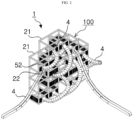
FIGS. 1 to 3 are schematic perspective views showing a slide tower system according to an embodiment of the present disclosure. -
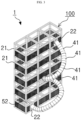
FIGS. 4 and5 are schematic views showing the slide tower system according to this embodiment. -
FIG. 6 is a schematic view showing a portion of the slide tower system according to this embodiment. -
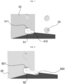
FIG. 7 is a schematic view showing an example of a start member of the slide tower system according to this embodiment. -
FIG. 8 is a schematic diagram showing an example of an landing member of the slide tower system according to this embodiment. -
FIG. 9 is a schematic diagram showing a control state of the slide tower system according to this embodiment. -
FIG. 10 is a schematic diagram showing an example of an opening/closing member of the slide tower system according to this embodiment. -
FIGS. 11 and12 are schematic diagrams showing other assembly examples of a tower body of the slide tower system according to this embodiment. - Hereinafter, a slide tower system according to a preferred embodiment according to the present disclosure will be described in detail with reference to the attached drawings.
- The embodiments of the present disclosure may be modified in various forms, and the scope of the present disclosure should not be construed as being limited to the embodiments described in detail below. The following embodiments are provided to more completely explain the present disclosure to a person having average knowledge in the art. Accordingly, the shapes of elements in the drawings may be exaggerated to emphasize a clearer explanation. It should be noted that in each drawing, the same parts are sometimes illustrated with the same reference numerals. Detailed descriptions of known functions and configurations that are judged to unnecessarily obscure the gist of the present disclosure are omitted.
-
FIGS. 1 to 12 are drawings showing aslide tower system 1 according to an embodiment of the present disclosure. Theslide tower system 1 according to this embodiment includesmodule members 2 formed in a polyhedral shape; and aconnection unit 3 configured to connect themodule members 2 to a floor to form atower body 100. - That is, the
tower body 100 is assembled by selectively assembling a plurality of themodule members 2 through theconnection unit 3. - At this time, the
tower body 100 is configured such that a plurality of themodule members 2 are vertically stacked as well as horizontally arranged in each layer, as thetower body 100 is assembled in a size and shape selected by the user; so the present disclosure may be applied appropriately according to the user's selection. - In the above, the
module member 2 may include amodule frame 21 forming each edge; andmodule walls 22 detachably attached to themodule frame 21 to form each surface. - That is, a plurality of module frames are connected as 'frames' in a 'polyhedral' shape to form the
module frame 21, and then themodule wall 22 is assembled and fastened to themodule frame 21 to form themodule member 2. - In the above, the module frame may be formed as a 'square pipe' having a 'pipe' shape with a 'square' cross-section; so it may be applied appropriately according to the user's choice.
- In the above, the
module wall 22 may be formed as a 'plate' in the shape of a 'plane polygon'; so it may be applied appropriately according to the user's choice. - In the above, the
connection unit 3 may be formed of a separate 'fixing element' such as a 'bolt', and may be formed of an 'adhesive element' such as a 'welding'; so the configuration and structure of the connection unit may suitably adopt a configuration and structure selected by a user from conventionally known technologies. - The
slide tower system 1 according to this embodiment includes a plurality ofslide members 4 selectively connected toconnection holes 23 formed selectively in themodule members 2 that form thetower body 100 and configured to allow sliding motion in a vertical manner. - That is, a plurality of the
slide members 4 are organically connected while being installed at different vertical heights in thetower body 100. - Accordingly, each of the
slide members 4 performs independent sliding play, thereby maximizing interest. - In the above, the
slide member 4 may be formed by connecting and assembling a plurality ofslide tubes 41, each of which is a hollow 'tube' with both ends penetrating, in a 'straight-line shape', a 'curved shape', or a 'vortex shape', and the configuration and structure thereof may suitably adopt a configuration and structure selected by the user. - In the above, the
slide tubes 41 may be assembled through separate 'coupling elements' such as 'bolts' and may be assembled with 'adhesive elements' such as 'welding', and the configuration and structure selected by the user may be suitably applied. - In the
module wall 22 of themodule member 2 above, theconnection hole 23 may be selectively formed according to the user's selection and connected to theslide member 4, and theconnection hole 23 may be not formed in themodule wall 22, and the configuration and structure selected by the user may be suitably applied. - In the above, the
module wall 22 having theconnection hole 23 may be applied at the end of theslide member 4 in an assembled state. - That is, as shown in
FIGS. 11 and12 , when assembling thetower body 100, themodule wall 22, which is integrally provided at the end of theslide member 4, may be fitted and assembled into the space between themodule members 2, thereby configuring thetower body 100. - The
slide tower system 1 according to this embodiment includes astart member 51 assembled into theconnection hole 23 formed in themodule wall 22 of themodule member 2 to allow a user to start to theslide member 4, and anlanding member 52 assembled into theconnection hole 23 to allow a user to arrive from theslide member 4 into the inside of themodule member 2. - That is, among the
connection holes 23 where both ends of theslide member 4 are respectively connected, thestart member 51 is fastened to theconnection hole 23 located at the top, and thelanding member 52 is fastened to theconnection hole 23 located at the bottom. Thus, when the user arrives the inside of theslide member 4 through thestart member 23, the user enjoys sliding by freely falling inside theslide member 4, and finally arrives the inside of themodule member 2 located at the bottom through thelanding member 52. - In the above, the
start member 51 may include a 'ring'-shaped start flange 511 fastened and assembled to the edge of theconnection hole 23 in themodule wall 22, and a 'hemispherical'start plate 512 formed by extending from thestart flange 511 with a length and having an open top and bottom so that the user may seat on the floor. - That is, the user may start to the inside of the
slide member 4 by placing the buttocks on thestart plate 512 in a state where thestart plate 512 is assembled to themodule member 2 via thestart flange 511. - In the above, the landing
member 52 may include a 'ring'-shapedlanding flange 521 fastened and assembled to the edge of theconnection hole 23 in themodule wall 22, and a 'hemispherical'landing plate 522 formed by extending from the landingflange 521 with a length and having an open top and bottom so that the user may seat on the floor. - That is, in a state where the
landing plate 522 is assembled to themodule member 2 via thelanding flange 521, a user who enjoys free-falling sliding inside theslide member 4 may land stably by decelerating with the buttocks being guided by thelanding plate 522. - In the above, the length of the
landing plate 522 is formed longer than the length of thestart plate 512, so that the user's deceleration guidance is facilitated, and the user's starting movement to theslide member 4 through thestart plate 512 may be performed more stably. - The
slide tower system 1 according to this embodiment, which is configured as above, includesdetection sensors 6 respectively provided in themodule members 2 to detect the departure status and the arrival status of the user, and a control unit 7 configured to perform operational control based on detection data obtained from thedetection sensors 6 and to display and control operational status of each of theslide members 4. - That is, the detection data for the departure status and the arrival status of the user detected through the
detection sensors 6 inside themodule member 2 are operationally operated and controlled through the control unit 7 to detect the usage status of eachslide member 4, so that the detection data is displayed through a separate display device (not shown) or controlled to restrict the usage. - Accordingly, safety in use is secured by controlling the simultaneous use of a
single slide member 4 by multiple people. - The detection data for the departure status and for arrival status of the user detected through the
detection sensors 6 are operationally operated and controlled through the control unit 7 to detect the usage status of eachslide member 4, so that the detection data is displayed through a separate display device (not shown) or controlled to restrict the usage. - Accordingly, safety in use is secured by controlling the simultaneous use of a
single slide member 4 by multiple people. - In the above, the
detection sensor 6 may be a 'light sensor' configured to detect the proximity of a user, or a 'motion sensor', a 'weight sensor', etc. configured to detect the motion of a user, and the configuration and structure of thedetection sensor 6 may suitably adopt a configuration and structure selected by a user from conventionally known technologies. - The
detection sensors 6 and the control unit 7 described above are electrically connected via wired or wireless communication to transmit the detection data, and thedetection sensors 6 may be applied appropriately according to the user's choice. - In the
slide tower system 1 according to this embodiment as described above, themodule members 2 may include a light-emittingsignal unit 8 that notifies the status that the user playing on the slide inside theslide member 4 arrives at themodule member 2 equipped with the landingmember 52. - That is, the detection data detected by each of the
detection sensors 6 provided in each of themodule members 2 are calculated through the control unit 7, and the user's application status for theslide member 4 where the user slides is detected. - By applying detection of the user's application status calculated in this way, each of the light-emitting
signal units 8 respectively provided in themodule members 2 connected to theslide member 4, which is in progress with sliding play, is controlled and driven, thereby informing the user in the future of the usage status of theslide member 4. - Therefore, safety in use is achieved.
- In the
slide tower system 1 according to this embodiment configured as above, a plurality of themodule members 2 andslide members 4 are implemented to be modified in various ways according to the user's selection, so that the positions of thestart members 51 and thelanding members 52 may be variably applied. - At this time, each of the
detection sensors 6 respectively provided to thestart members 51 and thelanding members 52 is electrically connected to the control unit 7 via a communication network/internet network, so that the transmission/reception and control of detection data may be changed and controlled in real time. Thus, the departure-arrival pairing may be changed through a software change operation of the control unit 7 even when the entrances and exits of theslide members 4 are changed in various ways. - That is, each of the
detection sensors 6 may be applied by selectively switching the role of user departure detection and arrival detection as needed, so that economic benefits and customized design quality may be improved through improved usability. - In the above, the
module member 2 may include an opening/closingmember 24 detachably fastened to open and close theconnection hole 23 of themodule member 2. - That is, when forming the
tower body 100 by selectively connecting a plurality ofslide members 4 to the connection holes 23 of themodule members 2, the opening/closingmember 24 is fastened to the unused connection holes 23, which are not connected to theslide members 4, to close the unused connection holes 23. - In addition, when the positions of a plurality of the
slide members 4 connected to themodule members 2 are changed in various ways according to the user's choice, the opening/closingmember 24 fastened to theconnection hole 23 may be separated to open theconnection hole 23 and to connect and assemble theslide members 4. - Accordingly, in the
tower body 100 that is installed to have a vertical height differently, users enjoying the slide play are prevented from unauthorized entry into the unused connection holes 23, thereby ensuring safety in use. - In addition, when changing the fastening position of the
slide member 4, the opening/closingmember 24 may be simply separated from theconnection hole 23 to open theconnection hole 23, thereby enabling easier and more organic connection work. - Therefore, usability is improved.
- In the above, the opening/closing
member 24 may be assembled to theconnection hole 23 through a separate 'fastening element' such as a 'bolt', and may be configured to be attached and detached by a 'detachable element', and thus a configuration and structure selected by the user may be suitably applied. - The
slide tower system 1 according to this embodiment as described above is characterized by a technical configuration in which a plurality of themodule members 2 selectively configurevarious tower bodies 100 of selected sizes and shapes through theconnection unit 3, and in which theslide members 4 in thetower body 100 are installed at different vertical heights and organically connected to perform an independent slide play. - The above-described embodiment of the present disclosure is merely exemplary, and a person skilled in the art to which the present disclosure belongs will readily recognize that various modifications and equivalent other embodiments are possible. Therefore, it will be readily understood that the present disclosure is not limited to the forms mentioned in the above detailed description. Accordingly, the true technical protection scope of the present disclosure should be determined by the technical idea of the appended claims. In addition, the present disclosure should be understood to include all modifications, equivalents, and substitutes within the idea and scope of the present disclosure defined by the appended claims.
Claims (4)
- A slide tower system comprising:module members formed in a polyhedral shape;a connection unit configured to connect the module members with respect to a base to form a tower body; anda plurality of slide members selectively connected to connection holes selectively formed in the module members that form the tower body and configured to allow sliding motion in a vertical manner.
- The slide tower system according to claim 1,
wherein one of the module members includes module frames configured to form each edge of the one of the module members, and module walls configured to be detachably attached to the module frames to form each surface of the module members. - The slide tower system according to claim 1, further comprising:a start member mounted to one connection hole selectively formed in one module wall of the module members, wherein the start member is configured to allow a user to start sliding on the slide member; andan landing member mounted to one connection hole selectively formed in one module wall of the module members, wherein the landing member is configured to allow the user to land in a space within the module members from the slide members.
- The slide tower system according to claim 1, further comprising:detection sensors provided in the respective module members and configured to detect a departure status and an arrival status of a user, respectively; anda control unit configured to perform operational control based on detection data obtained from the detection sensors to display and control an operational status of each of the slide members.
Applications Claiming Priority (2)
| Application Number | Priority Date | Filing Date | Title |
|---|---|---|---|
| KR1020220108831A KR102545810B1 (en) | 2022-08-30 | 2022-08-30 | A slide tower system |
| PCT/KR2023/010420 WO2024048997A1 (en) | 2022-08-30 | 2023-07-19 | Slide tower system |
Publications (2)
| Publication Number | Publication Date |
|---|---|
| EP4582150A1 true EP4582150A1 (en) | 2025-07-09 |
| EP4582150A4 EP4582150A4 (en) | 2025-12-24 |
Family
ID=86994770
Family Applications (1)
| Application Number | Title | Priority Date | Filing Date |
|---|---|---|---|
| EP23860679.2A Pending EP4582150A4 (en) | 2022-08-30 | 2023-07-19 | SLIDING TOWER SYSTEM |
Country Status (4)
| Country | Link |
|---|---|
| US (1) | US20260061331A1 (en) |
| EP (1) | EP4582150A4 (en) |
| KR (1) | KR102545810B1 (en) |
| WO (1) | WO2024048997A1 (en) |
Families Citing this family (1)
| Publication number | Priority date | Publication date | Assignee | Title |
|---|---|---|---|---|
| KR102545810B1 (en) * | 2022-08-30 | 2023-06-20 | (주)스페이스엔지니어링 | A slide tower system |
Family Cites Families (13)
| Publication number | Priority date | Publication date | Assignee | Title |
|---|---|---|---|---|
| US3632109A (en) * | 1969-07-22 | 1972-01-04 | Richard Dattner | Modular recreational unit and combinations thereof |
| US5226864A (en) * | 1991-11-04 | 1993-07-13 | Glenwood Systems Pty. Ltd. | Playground maze apparatus |
| US6099411A (en) * | 1999-09-21 | 2000-08-08 | Western Mill Fabricators, Inc. | Multi-layer and multi-chamber play structure |
| KR20090006955U (en) | 2008-01-03 | 2009-07-08 | (주)청화메디코스 | Straight perm |
| JP5961613B2 (en) | 2010-08-20 | 2016-08-02 | ザ・スカイライフ・カンパニー・インク | Material supply pack and method and system for manufacturing material supply pack |
| KR101263406B1 (en) | 2011-04-14 | 2013-05-10 | 주식회사 한빛티앤아이 | cellullar phone having earphone jack module type |
| US10702729B2 (en) * | 2017-03-21 | 2020-07-07 | Uatp Ip, Llc | Multi-level play equipment |
| US11338163B2 (en) * | 2018-09-21 | 2022-05-24 | Playcore Wisconsin, Inc. | Playground climber unit comprising one or more net-containing portions and/or one or more suspended tube portions |
| US20210016116A1 (en) * | 2018-09-25 | 2021-01-21 | Jimi Ip, Llc | Safety Check Apparatus for Challenge Course |
| KR102179008B1 (en) * | 2020-07-30 | 2020-11-16 | (주)신흥이앤지 | Frame module for amusement facilities |
| CN213192530U (en) * | 2020-09-29 | 2021-05-14 | 新乡市徐氏游乐设备有限公司 | Magic cube-shaped maze amusement equipment |
| KR102404799B1 (en) * | 2021-11-30 | 2022-06-02 | (주)스페이스엔지니어링 | A maze slide system |
| KR102545810B1 (en) * | 2022-08-30 | 2023-06-20 | (주)스페이스엔지니어링 | A slide tower system |
-
2022
- 2022-08-30 KR KR1020220108831A patent/KR102545810B1/en active Active
-
2023
- 2023-07-19 WO PCT/KR2023/010420 patent/WO2024048997A1/en not_active Ceased
- 2023-07-19 EP EP23860679.2A patent/EP4582150A4/en active Pending
- 2023-07-19 US US19/106,928 patent/US20260061331A1/en active Pending
Also Published As
| Publication number | Publication date |
|---|---|
| US20260061331A1 (en) | 2026-03-05 |
| KR102545810B1 (en) | 2023-06-20 |
| EP4582150A4 (en) | 2025-12-24 |
| WO2024048997A1 (en) | 2024-03-07 |
Similar Documents
| Publication | Publication Date | Title |
|---|---|---|
| US20090266267A1 (en) | System for tower- and cable-based transportation structure | |
| US20260061331A1 (en) | Slide tower system | |
| US6575403B1 (en) | Personnel lift device with automatic ascent and descent control | |
| KR101376703B1 (en) | Structure of tower type for extreme leisure sports | |
| US10702729B2 (en) | Multi-level play equipment | |
| US10376798B2 (en) | High angle tethered slide with freefall drop and variable radius swing | |
| JP2004513668A (en) | Multi-bay bungee cord acrobatic suspension and trampoline structure | |
| US20190358551A1 (en) | High Angle Tethered Slide with Freefall Drop and Variable Radius Swing | |
| KR101393650B1 (en) | Complex play facilities | |
| US20180296931A1 (en) | Adventure Park | |
| WO2006078174A1 (en) | Device for a gangway | |
| EP1781872A1 (en) | Observation tower | |
| KR102404799B1 (en) | A maze slide system | |
| KR200426581Y1 (en) | Sky Challenge Tower Facilities | |
| US10717015B2 (en) | High angle tethered slide with freefall drop and variable radius swing | |
| CN207956023U (en) | Floating load carrier | |
| KR102787202B1 (en) | Observation tower equipped with experiential facilities and park structure for including same | |
| KR102843857B1 (en) | Structure of complex adventure observation tower | |
| CN218685991U (en) | Ride-through and challenge type combined amusement device | |
| KR102832108B1 (en) | Complex observation tower | |
| KR102616733B1 (en) | Total playing facilities using unit clamp assembly for connecting of orthographic or intersecting component | |
| KR102843856B1 (en) | Complex adventure observation tower | |
| KR20010074289A (en) | tower framework for recreation facilities, ejection-recreation facilities, big swing-recreation facilities and complex recreation facilities | |
| CN213220888U (en) | Amusement facility with spherical structure | |
| KR100789096B1 (en) | Revolving tower with amusement facilities |
Legal Events
| Date | Code | Title | Description |
|---|---|---|---|
| STAA | Information on the status of an ep patent application or granted ep patent |
Free format text: STATUS: THE INTERNATIONAL PUBLICATION HAS BEEN MADE |
|
| PUAI | Public reference made under article 153(3) epc to a published international application that has entered the european phase |
Free format text: ORIGINAL CODE: 0009012 |
|
| STAA | Information on the status of an ep patent application or granted ep patent |
Free format text: STATUS: REQUEST FOR EXAMINATION WAS MADE |
|
| 17P | Request for examination filed |
Effective date: 20250320 |
|
| AK | Designated contracting states |
Kind code of ref document: A1 Designated state(s): AL AT BE BG CH CY CZ DE DK EE ES FI FR GB GR HR HU IE IS IT LI LT LU LV MC ME MK MT NL NO PL PT RO RS SE SI SK SM TR |
|
| REG | Reference to a national code |
Ref country code: DE Ref legal event code: R079 Free format text: PREVIOUS MAIN CLASS: A63B0017040000 Ipc: A63G0021020000 |
|
| DAV | Request for validation of the european patent (deleted) | ||
| DAX | Request for extension of the european patent (deleted) | ||
| A4 | Supplementary search report drawn up and despatched |
Effective date: 20251125 |
|
| RIC1 | Information provided on ipc code assigned before grant |
Ipc: A63G 21/02 20060101AFI20251119BHEP Ipc: A63B 9/00 20060101ALN20251119BHEP Ipc: A63G 21/10 20060101ALN20251119BHEP |