EP4582033A2 - Vorrichtungen, systeme und verfahren zur behandlung des linken vorhofanhangs - Google Patents
Vorrichtungen, systeme und verfahren zur behandlung des linken vorhofanhangs Download PDFInfo
- Publication number
- EP4582033A2 EP4582033A2 EP25177737.1A EP25177737A EP4582033A2 EP 4582033 A2 EP4582033 A2 EP 4582033A2 EP 25177737 A EP25177737 A EP 25177737A EP 4582033 A2 EP4582033 A2 EP 4582033A2
- Authority
- EP
- European Patent Office
- Prior art keywords
- contact member
- atrial appendage
- left atrial
- implant
- securing element
- Prior art date
- Legal status (The legal status is an assumption and is not a legal conclusion. Google has not performed a legal analysis and makes no representation as to the accuracy of the status listed.)
- Pending
Links
Images


Classifications
-
- A—HUMAN NECESSITIES
- A61—MEDICAL OR VETERINARY SCIENCE; HYGIENE
- A61B—DIAGNOSIS; SURGERY; IDENTIFICATION
- A61B17/00—Surgical instruments, devices or methods
- A61B17/12—Surgical instruments, devices or methods for ligaturing or otherwise compressing tubular parts of the body, e.g. blood vessels or umbilical cord
- A61B17/12022—Occluding by internal devices, e.g. balloons or releasable wires
- A61B17/12027—Type of occlusion
- A61B17/12031—Type of occlusion complete occlusion
-
- A—HUMAN NECESSITIES
- A61—MEDICAL OR VETERINARY SCIENCE; HYGIENE
- A61B—DIAGNOSIS; SURGERY; IDENTIFICATION
- A61B17/00—Surgical instruments, devices or methods
- A61B17/12—Surgical instruments, devices or methods for ligaturing or otherwise compressing tubular parts of the body, e.g. blood vessels or umbilical cord
- A61B17/12022—Occluding by internal devices, e.g. balloons or releasable wires
- A61B17/12099—Occluding by internal devices, e.g. balloons or releasable wires characterised by the location of the occluder
- A61B17/12122—Occluding by internal devices, e.g. balloons or releasable wires characterised by the location of the occluder within the heart
-
- A—HUMAN NECESSITIES
- A61—MEDICAL OR VETERINARY SCIENCE; HYGIENE
- A61B—DIAGNOSIS; SURGERY; IDENTIFICATION
- A61B17/00—Surgical instruments, devices or methods
- A61B17/12—Surgical instruments, devices or methods for ligaturing or otherwise compressing tubular parts of the body, e.g. blood vessels or umbilical cord
- A61B17/12022—Occluding by internal devices, e.g. balloons or releasable wires
- A61B17/12131—Occluding by internal devices, e.g. balloons or releasable wires characterised by the type of occluding device
- A61B17/12168—Occluding by internal devices, e.g. balloons or releasable wires characterised by the type of occluding device having a mesh structure
- A61B17/12172—Occluding by internal devices, e.g. balloons or releasable wires characterised by the type of occluding device having a mesh structure having a pre-set deployed three-dimensional shape
-
- A—HUMAN NECESSITIES
- A61—MEDICAL OR VETERINARY SCIENCE; HYGIENE
- A61B—DIAGNOSIS; SURGERY; IDENTIFICATION
- A61B34/00—Computer-aided surgery; Manipulators or robots specially adapted for use in surgery
- A61B34/30—Surgical robots
-
- A—HUMAN NECESSITIES
- A61—MEDICAL OR VETERINARY SCIENCE; HYGIENE
- A61B—DIAGNOSIS; SURGERY; IDENTIFICATION
- A61B90/00—Instruments, implements or accessories specially adapted for surgery or diagnosis and not covered by any of the groups A61B1/00 - A61B50/00, e.g. for luxation treatment or for protecting wound edges
- A61B90/50—Supports for surgical instruments, e.g. articulated arms
-
- A—HUMAN NECESSITIES
- A61—MEDICAL OR VETERINARY SCIENCE; HYGIENE
- A61B—DIAGNOSIS; SURGERY; IDENTIFICATION
- A61B17/00—Surgical instruments, devices or methods
- A61B2017/00367—Details of actuation of instruments, e.g. relations between pushing buttons, or the like, and activation of the tool, working tip, or the like
-
- A—HUMAN NECESSITIES
- A61—MEDICAL OR VETERINARY SCIENCE; HYGIENE
- A61B—DIAGNOSIS; SURGERY; IDENTIFICATION
- A61B17/00—Surgical instruments, devices or methods
- A61B17/064—Surgical staples, i.e. penetrating the tissue
- A61B2017/0641—Surgical staples, i.e. penetrating the tissue having at least three legs as part of one single body
-
- A—HUMAN NECESSITIES
- A61—MEDICAL OR VETERINARY SCIENCE; HYGIENE
- A61B—DIAGNOSIS; SURGERY; IDENTIFICATION
- A61B17/00—Surgical instruments, devices or methods
- A61B17/12—Surgical instruments, devices or methods for ligaturing or otherwise compressing tubular parts of the body, e.g. blood vessels or umbilical cord
- A61B17/12022—Occluding by internal devices, e.g. balloons or releasable wires
- A61B2017/1205—Introduction devices
- A61B2017/12054—Details concerning the detachment of the occluding device from the introduction device
- A61B2017/12095—Threaded connection
-
- A—HUMAN NECESSITIES
- A61—MEDICAL OR VETERINARY SCIENCE; HYGIENE
- A61B—DIAGNOSIS; SURGERY; IDENTIFICATION
- A61B90/00—Instruments, implements or accessories specially adapted for surgery or diagnosis and not covered by any of the groups A61B1/00 - A61B50/00, e.g. for luxation treatment or for protecting wound edges
- A61B90/06—Measuring instruments not otherwise provided for
- A61B2090/061—Measuring instruments not otherwise provided for for measuring dimensions, e.g. length
-
- A—HUMAN NECESSITIES
- A61—MEDICAL OR VETERINARY SCIENCE; HYGIENE
- A61B—DIAGNOSIS; SURGERY; IDENTIFICATION
- A61B90/00—Instruments, implements or accessories specially adapted for surgery or diagnosis and not covered by any of the groups A61B1/00 - A61B50/00, e.g. for luxation treatment or for protecting wound edges
- A61B90/50—Supports for surgical instruments, e.g. articulated arms
- A61B2090/508—Supports for surgical instruments, e.g. articulated arms with releasable brake mechanisms
-
- A—HUMAN NECESSITIES
- A61—MEDICAL OR VETERINARY SCIENCE; HYGIENE
- A61M—DEVICES FOR INTRODUCING MEDIA INTO, OR ONTO, THE BODY; DEVICES FOR TRANSDUCING BODY MEDIA OR FOR TAKING MEDIA FROM THE BODY; DEVICES FOR PRODUCING OR ENDING SLEEP OR STUPOR
- A61M5/00—Devices for bringing media into the body in a subcutaneous, intra-vascular or intramuscular way; Accessories therefor, e.g. filling or cleaning devices, arm-rests
- A61M5/007—Devices for bringing media into the body in a subcutaneous, intra-vascular or intramuscular way; Accessories therefor, e.g. filling or cleaning devices, arm-rests for contrast media
Definitions
- LAA closure has been typically performed in high-risk patients due to possible stroke risk.
- LAA closure techniques are generally performed to block emboli from exiting the LAA.
- Typical surgical closure includes stitching the opening closed via left atrium entry.
- Other techniques include the application of external clamps such as ATRICLIP manufactured by Atricure where a Nitinol device is used to clamp the appendage without opening the left atrium to exclude the appendage from left atrium blood circulation.
- a plug to close the appendage from the inside of the left atrium.
- Such plugs can be constructed from a laser cut Nitinol tube expanded to a semispherical shape.
- the portion exposed to the left atrium can be covered with cover -such as a thin micron membrane made from polyethylene terephthalate.
- the membrane can act as a blood barrier to prevent flow from flowing through and between one or more struts of the plug. Typical sizes range between approximately 20 mm and 35 mm in diameter and approximately 20 mm and 40 mm in depth.
- the device can have anchors protruding from an outer surface of the device intended to engage the wall of the appendage and prevent movement post deployment.
- the catheter can include an outer sheath coupled with a first connector, a first dial coupled with the outer sheath, an inner catheter member configured to rotate the implant when a distal end portion of the inner tube is engaged with the implant, and a second dial coupled with the inner catheter member.
- any arrangements of the devices, systems, and methods disclosed herein can include, in additional arrangements, one or more of the following features, components, and/or details, in any combination with any of the other features, components, and/or details of any other arrangements disclosed herein: wherein the system is configured to cause a rotating portion of the implant to move from a first state to a second, expanded state and to move an outside surface of the rotating portion of the implant against an inner wall surface of the left atrial appendage; further including a second inner catheter member and a third dial coupled with the second inner catheter member, wherein the third dial is configured to rotate the second inner catheter member and to move a locking portion of the implant toward a rotating portion of the implant when the third dial is rotated in a first direction; wherein the locking portion comprises one or more arms extending away from a body portion of the implant and configured to penetrate into the tissue of the left atrial appendage that has constricted and gathered inwardly around an outside surface of a portion of the implant; wherein the locking portion comprises one or more arms extending away from
- any arrangements of the devices, systems, and methods disclosed herein can include, in additional arrangements, one or more of the following features, components, and/or details, in any combination with any of the other features, components, and/or details of any other arrangements disclosed herein: wherein the other sheath comprises an inner layer and an outer layer positioned over the inner layer along at least a portion of a length of the inner layer such that a distal end portion of the inner layer having a plurality of openings therein is not covered by the outer layer; wherein the plurality of openings comprise a plurality of angled slits formed in the inner layer of the outer sheath, wherein the plurality of angled slits are configured to increase a flexibility of the outer sheath and to permit a passage of a contrast media through the angled slits; further including a support stand for supporting the catheter and at least a guide catheter, wherein the support stand is configured to be positioned on a support surface, such as a bed or table, or on a patient's body;
- Also disclosed herein are arrangements of a method of treating a left atrial appendage that can include advancing an implant into the left atrial appendage, engaging an inner wall surface of the left atrial appendage with a portion of the implant, rotating the implant in a first direction from an initial position by a first predetermined angle, moving the implant in a proximal direction by a first predetermined distance, and rotating the implant in the first direction by a second predetermined angle.
- the method can include twisting the left atrial appendage and/or securing the left atrial appendage in a twisted position.
- Any arrangements of the methods, devices and systems of treating a left atrial appendage disclosed herein can include, in additional arrangements, one or more of the following steps, features, components, and/or details, in any combination with any of the other steps, features, components, and/or details of any other arrangements disclosed herein: wherein twisting the left atrial appendage can include engaging a wall portion on an inside of the left atrial appendage with a contact member and rotating the contact member from a first rotational position (also referred to herein as a first position) to a second rotational position (also referred to herein as a second position) to twist the left atrial appendage; wherein engaging a wall portion on an inside of the left atrial appendage with a contact member can include advancing a deployment device into the left atrial app
- any arrangements of the methods, devices and systems of treating a left atrial appendage disclosed herein can include, in additional arrangements, one or more of the following steps, features, components, and/or details, in any combination with any of the other steps, features, components, and/or details of any other arrangements disclosed herein: wherein twisting the left atrial appendage can include rotating a portion of the left atrial appendage about an axis from a first rotational position to a second rotational position to twist the left atrial appendage; wherein rotating a portion of the left atrial appendage about an axis from a first rotational position to a second rotational position to twist the left atrial appendage can include rotating the portion of the left atrial appendage at least approximately 90° in either direction from the first rotational position; wherein rotating a portion of the left atrial appendage about an axis from a first rotational position to a second rotational position to twist the left atrial appendage can include rotating the portion of the left atrial appendage at least
- the method can include twisting tissue of the heart to constrict the ostium of the left atrial appendage and/or securing tissue that has gathered as a result of twisting tissue of the heart in a gathered position.
- any arrangements of the methods, devices and systems of closing the ostium of a left atrial appendage disclosed herein can include, in additional arrangements, one or more of the following steps, features, components, and/or details, in any combination with any of the other steps, features, components, and/or details of any other arrangements disclosed herein: wherein securing the tissue of the heart in the gathered position can include advancing a securing element into the gathered tissue; wherein the securing element can be a suture; and/or wherein the securing element can be a tissue anchor.
- the contact member can be configured to move from the first state to the second state so that at least a portion of the contact member engages a wall portion of the LAA when the contact member is advanced into the LAA.
- the contact member can be moved or expanded from the first state to the second state in the LA or in the LAA.
- the contact member can be configured to remain in a fixed state and/or size during the entire procedure, wherein the contact member can be extended past a distal end of the delivery catheter (or an outside tube of the delivery catheter can be withdrawn) and advanced into contact or engagement with a wall portion of the LAA, and then twisted. This can be done without changing a size of the contact member and/or without expanding the contact member.
- any arrangements of the devices and systems disclosed herein can, in additional arrangements, include one or more of the following features or details, in any combination: wherein the implant has a plurality of tissue anchors on an outside surface thereof; wherein the plurality of tissue anchors on the outside surface of the implant configured to engage an inner wall surface of the left atrial appendage after the implant has been moved to the second state; wherein the implant can include a securing element configured to engage with a tissue portion of the heart adjacent to the left atrial appendage; wherein the second rotational position can be at least one-quarter or approximately one-quarter of a complete rotation (i.e., 90° or approximately 90°) relative to the first rotational position; wherein the second rotational position can be at least one-half or approximately one-half of a complete rotation (i.e., 180° or approximately 180°) relative to the first rotational position; wherein the second rotational position can be from one-quarter or approximately one-quarter of a complete rotation (i.e., 90° or approximately 90°) to one or
- Any arrangements of a method of closing or occluding an LAA disclosed herein can include advancing a deployment device having an implant into the left atrial appendage, wherein the implant can be configured to be moved from a first state to a second state.
- the implant can be configured to be moved from a first state to a second state.
- at least a portion of the implant can be enlarged in a radial direction when the implant is in the second state as compared to the first state.
- the method can further include moving the implant from the first state to the second state within the left atrial appendage so as to move at least a portion of an outside wall of the implant or one or more tissue anchors extending away from an outer surface of the implant against at least a portion of an inner wall surface of the left atrial appendage, rotating the implant from a first rotational position to a second rotational position to twist the left atrial appendage, and preventing the implant from rotating back to the first rotational position.
- any arrangements of methods of closing or occluding an LAA disclosed herein can, in some additional arrangements, include one or more of the following steps, in any combination and in any combination with any of the other steps, features, or other details of any other arrangements: wherein the implant is self-expanding and wherein moving the implant from the first state to the second state comprises advancing the implant out of a distal end of the deployment device; wherein engaging a wall portion on an inside of the LAA comprises engaging a wall portion on an inside of the LAA with one or more tissue anchors positioned on an outside surface of the implant; wherein preventing the implant from rotating back to the first rotational position comprises engaging a tissue wall with an anchor element to prevent relative movement between the implant and the tissue wall; wherein preventing the implant from rotating back to the first rotational position comprises engaging a tissue wall with an anchor element, and wherein the anchor element is configured to be secured to the implant to prevent a rotation between the implant and the anchor element; wherein preventing the implant from rotating back to the first rotational position comprises engaging a
- any arrangements of the methods of closing or occluding an LAA disclosed herein can, in any additional arrangements, include one or more of the following steps, in any combination and in any combination with any of the other steps, features, or other details of any other arrangements: wherein rotating the implant from the first rotational position to the second rotational position to twist the left atrial appendage can include rotating the implant at least one-quarter or approximately one-quarter of a complete rotation (i.e., 90° or approximately 90°) relative to the first rotational position; wherein rotating the implant from the first rotational position to the second rotational position to twist the left atrial appendage can include rotating the implant at least one-half or approximately one-half of a complete rotation (i.e., 180° or approximately 180°) in either direction from the first rotational position; wherein rotating the implant from the first rotational position to the second rotational position to twist the left atrial appendage can include rotating the implant from one-quarter or approximately one-quarter of a complete rotation (i.e., 90° or approximately 90°)
- Some arrangements of the devices and systems for closing or occluding an LAA disclosed herein can include an implant configured to move between a first state and a second state, and a catheter configured to advance the implant into the left atrial appendage when the implant is in the first state and to cause the implant to move from the first state to the second state so that an outside surface of the implant moves against an inner wall surface of the left atrial appendage after the implant has been advanced into the left atrial appendage.
- the catheter can be configured to rotate the implant in a first direction from a first rotational position to a second rotational position so that the implant can twist at least a portion of the left atrial appendage when the implant is in the second state.
- Some arrangements of apparatuses for treating the left atrial appendage disclosed herein can include a device configured to be inserted into the left atrial appendage and to engage the left atrial appendage tissue while the device is rotated to a rotated position to close the blood communication between the left atrial appendage and the left atrium.
- Disclosed herein are arrangements of devices for treating a left atrial appendage that include an implant having a contact member and a catheter configured to advance the contact member into the left atrial appendage and to cause the contact member to move against an inner wall surface of the left atrial appendage, wherein the catheter is configured to exert a torque on the contact member when at least a portion of the catheter is rotated until a predetermine torque level is reached to rotate the contact member from a first rotational position to a second rotational position so that the contact member can twist at least a portion of the left atrial appendage.
- the contact member can be configured to be moved against the inner wall surface of the left atrial appendage without changing a state or shape of the contact member, and/or the contact member can be configured to be movable or expandable from a first state to a second state.
- Disclosed herein are arrangements of devices for reducing an opening of the left atrial appendage that include a contact member and a securing element, wherein the contact member is configured to engage a tissue surface of the left atrial appendage, the contact member is configured to rotate at least a portion of the left atrial appendage in a first direction from a first rotational position to a second rotational position and to cause the opening of the left atrial appendage to reduce in size from a first size to a second size, and/or the securing element is configured to engage with at least a portion of tissue adjacent to the opening of the left atrial appendage and to prevent the opening of the left atrial appendage from expanding to the first size.
- the contact member can be configured to engage a tissue surface on an outside surface of the left atrial appendage. Further, in any arrangements disclosed herein, the contact member can be configured to engage the tissue surface of the left atrial appendage without changing a state or shape of the contact member.
- any arrangements of the devices disclosed herein can include, in additional arrangements, one or more of the following features, components, and/or details, in any combination with any of the other features, components, and/or details of any other arrangements disclosed herein: wherein the device further includes a delivery catheter; wherein the device further includes an implant of any of the implant arrangements disclosed herein that is advanceable through the delivery catheter when the implant is in a first state; wherein the implant includes a first stage portion and a second stage portion that are each independently deployable to at least a second operable or deployed state; wherein the first stage portion is configured to be at least partially deployed before a second stage portion is deployed; wherein the first stage portion is configured to be positioned near a distal end portion of the LAA; wherein the second stage portion is configured to constrict an opening of the LAA when the second stage portion is in the second state; wherein second stage portion is configured to close the opening of the LAA when the second stage portion is in the second state; wherein second stage portion is configured to fold one or more tissue portions surrounding or adjacent to the
- Disclosed herein are additional arrangements of treatment methods that include advancing a deployment device having an implant into the left atrial appendage, moving at least a portion of an outside surface of the implant or one or more tissue anchors extending away from an outer surface of the implant against an inner wall surface of the left atrial appendage, rotating the implant from a first rotational position to a second rotational position to twist the left atrial appendage, and preventing the implant from rotating back to the first rotational position.
- the method can include moving at least a portion of an outside surface of the implant or one or more tissue anchors extending away from an outer surface of the implant against an inner wall surface of the left atrial appendage without changing a shape or size of the implant, and/or moving the implant from a first state to a second state, and wherein at least a portion of the implant is enlarged in a radial direction when the implant is in the second state as compared to the first state.
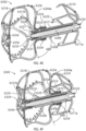
- Disclosed herein are additional arrangements of devices and systems for closing an LAA that can include a clamp device having a first member and a second member and be configured to move between a closed position and an open position, a first guide device configured to be advanceable into the LAA, and a second guide device configured to be advanceable into a pericardial space outside of the LAA and moved so that an end portion of the second guide device is in approximate axial alignment with an end portion of the first guide device.
- At least one of the first and second members of the clamp device can be substantially rigid; the clamp device can have an opening sized so that the clamp device can be passed over the LAA when the clamp device is in the open position; and/or at least one of the first and second members of the clamp device can be configured to substantially flatten and close a portion of the LAA when the clamp device is moved to the closed position.
- the clamp device can include only the first member and the second member.
- the clamp device can further include a third member and a fourth member connected together in an end to end arrangement and defining an opening in the clamp device that is sized and configured to pass over an outside surface of the LAA.
- the device can further include a delivery catheter having an outer sheath and a guide lumen, the guide lumen configured to receive and track over the second guide device.
- the first member of the clamp device can be rigid and the second member of the clamp device can comprise a suture.
- the method can include advancing a first guide device into the LAA, advancing a second guide device into a pericardial space outside of the LAA, approximately aligning an end portion of the second guide device with an end portion of the first guide device, advancing a delivery catheter over the second guide device, advancing a clamp device having a first member and a second member from the delivery catheter, opening the clamp device from a closed position to an open position, advancing the clamp device over an outside surface of the LAA toward a neck portion of the LAA, and/or substantially flattening and closing the neck portion of the LAA by closing the clamp device from the open position to the closed position.
- any arrangements of the methods of closing or occluding the LAA can include, in additional arrangements, one or more of the following features, components, steps, and/or details, in any combination with any of the other features, components, steps, and/or details of any other arrangements disclosed herein: wherein moving the clamp device from the closed position to the open position comprises advancing the clamp device past a distal end of the delivery catheter so that the clamp device can automatically move to the open position; wherein the delivery catheter has a guide lumen, the guide lumen being configured to receive and track over the second guide device; wherein the delivery catheter has an outer sheath; wherein at least one of the first and second members of the clamp device is substantially rigid; wherein at least one of the first and second members of the clamp device has a substantially planar contact surface, the contact surface being the surface configured to contact an outside surface of the LAA; wherein the delivery catheter has an outer sheath; wherein the clamp device comprises a least four substantially rigid members connected together in an end to end arrangement and defining an opening in the clamp device that is
- any implant and/or device or system arrangements disclosed herein can be adapted and/or used for treatment of any tissue condition in a body that is desired to be occluded, restricted, or closed.
- some arrangements of the devices and systems for treating a tissue condition disclosed herein can include an implant comprising a contact member that can be (but is not required to be) configured to move between a first state and a second state and a securing element, wherein the contact member can be configured to move from the first state to the second state so that at least a portion of the contact member engages a wall portion of the tissue condition after the contact member has been advanced into the tissue condition, the contact member can be configured to rotate at least in a first direction from a first rotational position to a second rotational position, the contact member can be configured to twist at least a portion of the tissue of the tissue condition in the first direction when the contact member is rotated from the first rotational position to the second rotational position, and/or the securing element can be configured to prevent a rotation of at least
- the devices and systems for treating a tissue condition disclosed herein can include an implant having a contact member that can be (but is not required to be) configured to move between a first state and a second state, a catheter configured to advance the contact member into the tissue condition when the contact member is in the first state and to cause the contact member to move from the first state to the second state so that an outside surface of the contact member engages at least one wall surface of the tissue condition after the contact member has been advanced into or adjacent to the tissue condition, wherein the catheter is configured to exert a torque on the contact member when at least a portion of the catheter is rotated until a predetermine torque level is reached to rotate the contact member from a first rotational position to a second rotational position so that the contact member can twist at least a portion of the tissue condition.
- the tissue condition can be a cavity, a chamber, an opening, a passageway, a tear in the tissue, two adjacent or adjoining tissue surfaces, or otherwise.
- some arrangements of the devices and systems for treating a tissue condition disclosed herein can include a method of treating a tissue condition, comprising advancing a deployment device having an implant into or adjacent to the tissue condition, wherein the implant can be (but is not required to be) configured to be moved from a first state to a second state, and wherein at least a portion of the implant can be enlarged in a radial direction when the implant is in the second state as compared to the first state, moving the implant from the first state to the second state within the tissue condition so as to move at least a portion of an outside surface of the implant or one or more tissue anchors extending away from an outer surface of the implant against at least one wall surface of the tissue condition, rotating the implant from a first rotational position to a second rotational position to twist the tissue condition, and/or preventing the implant from rotating back to the first rotational position.
- any implant and/or device or system arrangements disclosed herein can be adapted and/or used for treatment of any tissue condition in a body that is desired to be occluded, reshaped, restricted, or closed.
- some arrangements of the devices and systems for treating a tissue condition disclosed herein can include an implant comprising a contact member that is configured to engage a wall portion of the tissue condition after the contact member has been advanced into the tissue condition, the contact member can be configured to rotate at least in a first direction from a first rotational position to a second rotational position, the contact member can be configured to twist at least a portion of the tissue of the tissue condition in the first direction when the contact member is rotated from the first rotational position to the second rotational position, and/or the securing element can be configured to prevent a rotation of at least a portion of the tissue of the tissue condition in a second direction when the securing element is in an operable state, wherein the second direction is opposite to the first direction.
- the tissue condition can be a cavity
- some arrangements of the devices and systems for treating a tissue condition disclosed herein can include a method of treating a tissue condition, comprising advancing a deployment device having an implant into or adjacent to the tissue condition, and wherein at least a portion of the implant engages a wall surface of the tissue condition, rotating the implant from a first rotational position to a second rotational position to twist the tissue condition, and/or preventing the implant from rotating back to the first rotational position.
- a device for treating a left atrial appendage can include an implant that can have a contact member configured to engage an inside tissue surface of the left atrial appendage and configured to rotate in at least a first direction from a first position to at least a second position so as to twist the left atrial appendage when the contact member is engaged with an inside tissue surface of the left atrial appendage, and a securing element configured to move between a first position in which the securing element is decoupled from the contact member and a second position in which the securing element is coupled with the contact member.
- the contact member can be configured to rotate at least in the first direction from the first position to the second position when a torque is applied to the contact member.
- any arrangements of the methods, devices and systems for treating a left atrial appendage disclosed herein can include, in additional arrangements, one or more of the following steps, features, components, and/or details, in any combination with any of the other steps, features, components, and/or details of any other arrangements disclosed herein: wherein the contact member can be configured to rotate at least in the first direction from a first position to at least a second position to twist the left atrial appendage and reduce a size of an ostium of the left atrial appendage from a first size to a second size when the contact member is engaged with an inside tissue surface or the left atrial appendage; wherein the implant can be configured to inhibit the ostium of the left atrial appendage from enlarging back to the first size; wherein the device can be configured such that the contact member can be removed from the left atrial appendage after the securing element has been deployed to the operable state of the securing element; wherein the device can be configured such that the contact member can be removed from the left atrial
- any arrangements of the methods, devices and systems for treating a left atrial appendage disclosed herein can include, in additional arrangements, one or more of the following steps, features, components, and/or details, in any combination with any of the other steps, features, components, and/or details of any other arrangements disclosed herein: wherein the device can be configured to cause a tissue of the left atrium and/or the left atrial appendage to constrict around an outer surface of a body portion of the implant when the contact member is rotated to the second position; wherein the securing element can be configured to engage with the tissue that has constricted around the outer surface of the body portion of the implant to prevent rotation of the implant in a second direction that is opposite to the first direction; wherein, in an operable position, the securing element can be configured to at least inhibit the contact member from rotating back to the first position; wherein the securing element can be configured to prevent a rotation of at least a portion of the left atrial appendage in a second direction when the securing element is implanted in
- any arrangements of the methods, devices and systems for treating a left atrial appendage disclosed herein can include, in additional arrangements, one or more of the following steps, features, components, and/or details, in any combination with any of the other steps, features, components, and/or details of any other arrangements disclosed herein: including a restraint configured to be movable in an axial direction relative to at least a portion of the securing element between a first position in which the plurality of arms of the securing element are restrained by the restraint and a second position in which the plurality of arms of the securing element are not restrained by the restraint, wherein the second axial position can be closer to the first portion of the implant than the first axial position; wherein the restraint can be configured to be movable in an axial direction relative to at least a portion of the securing element from the second position in which the plurality of arms of the securing element are not restrained by the restraint to the first position in which the plurality of arms of the securing
- Also disclosed herein are arrangements of a method of treating a left atrial appendage that can include advancing a deployment device having an implant into the left atrium, moving at least a portion of an outer surface of a first portion of the implant and/or one or more tissue anchors on or adjacent to the outer surface of the first portion of the implant against an inner wall surface of the left atrial appendage, and rotating the first portion of the implant from a first position to a second position to twist the left atrial appendage from a first position to a second position, and moving a second portion of the implant from a first state in which the second portion of the implant spins freely relative to the first portion of the implant to a second state in which the second portion of the implant can be rotationally locked to the first portion of the implant.
- any arrangements of the methods, devices and systems for treating a left atrial appendage disclosed herein can include, in additional arrangements, one or more of the following steps, features, components, and/or details, in any combination with any of the other steps, features, components, and/or details of any other arrangements disclosed herein: wherein the second portion of the implant can be spaced apart from the first portion of the implant when the second portion of the implant is in the first state and the second portion of the implant is engaged with the first portion of the implant when the second portion of the implant is in the second state; including rotating the first portion of the implant until at least a portion of the left atrial appendage constricts around a portion of the implant; including rotating the first portion of the implant until an ostium of the left atrial appendage constricts around a portion of the implant; wherein the method can have engaging with the second portion of the implant a tissue that has constricted as a result of the rotation of the first portion of the implant; and/or wherein moving the second portion of the implant from the first state to the second
- a device for treating a left atrial appendage can include an implant device that can include a first implant member configured to engage an inside tissue surface of a first portion of the left atrial appendage and a second implant member configured to engage an inside tissue surface of a second portion of the left atrial appendage spaced apart from the first portion of the left atrial appendage.
- the device can be configured to rotate the first implant member in a first direction.
- the device can be configured to rotate the second implant member in a second direction that is opposite to the first direction.
- a device for treating a left atrial appendage can include an implant device that can include a first implant member configured to engage an inside tissue surface of a first portion of the left atrial appendage and a second implant member configured to engage an inside tissue surface of a second portion of the left atrial appendage spaced apart from the first portion of the left atrial appendage.
- the device can be configured to rotate the first implant member in a first direction. Further, in some arrangements, the device can be configured to also rotate the second implant member in the first direction.
- the rotation used to twist closed or occluded (completely or substantially) the LAA for any arrangements disclosed herein may be as little as a quarter of a turn (i.e., revolution), a half turn, a complete turn, up to as much as multiple turns for deeper or longer LAAs.
- the securing feature or element (also referred to herein as an anchoring element) in any arrangements disclosed herein can have a single arm or multiple arms which can be connected to the implant body that is positioned and rotated within the closed or substantially closed LAA.
- the securing feature or element can also be configured to engage tissue adjacent to the ostium of the LAA.
- the securing element can be configured to merely compress the tissue of the left atrium and/or the left atrial appendage that has constricted around an outer surface of a body portion of the implant between a distal surface of the securing element and the contact member to prevent rotation of the implant in the second direction, i.e., after the contact member has been rotated to the second rotational position, without penetrating into such tissue.
- the securing element can have a body portion that is smooth an nonobtrusive or nonpenetrating, e.g., so that the securing element does not have any tissue penetrating features on it that extend toward the tissue surfaces.
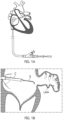
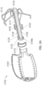
- the catheter 112 having the implant device 102 therein can be advanced into a desired position within the LAA and, while holding the implant device 102 in a stationary axial position by maintaining the core member 113 of the catheter 112 in a stationary axial position, the outer sleeve 114 of the catheter 112 can be retracted or withdrawn so as to expose and/or unrestrain the contact member 104 of the implant device 102.
- the contact member 104 can be self-expanding in a radial direction so that, when a restraint is removed from the contact member 104, the contact member 104 can expand against an inner surface or wall of the LAA automatically.
- the contact member 104 can be mechanically expandable, such as by a balloon expander, so as to expand against inside surface or wall of the LAA.
- Figure 2B illustrates the contact number 104 after it has been expanded against an inside wall of the LAA distal to an ostium or opening O of the LAA.
- the contact member can be configured to remain in a first state within the catheter, during the entire treatment procedure, and/or thereafter.
- the contact member can be configured such that the contact member is deployed from the catheter and advanced into contact with a tissue surface of an inside wall of the LAA, engage the tissue surface of the inside wall of the LAA, and cause the LAA to twist when a torque and/or rotation is applied to the contact member, all without changing the state of the contact member.
- a contact member can be configured to be advanced into the pericardial space around an outside of the LAA to engage an outside surface of the LAA and to and cause the LAA to twist when a torque and/or rotation is applied to the contact member.
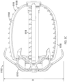
- the contact member 104 can have a plurality of teeth, cleats, barbs, nubs, texture, studs, anchors or other tissue engaging features 118 or other similar features configured to penetrate or engage the tissue of the LAA that are configured to penetrate into a tissue within the LAA when the contact member 104 is expanded against the tissue of the LAA and/or when the contact member 104 is rotated or twisted within the LAA.
- tissue anchors teeth, cleats, barbs, nubs, texture, studs, anchors and other tissue engaging features or features configured to grip or engage the tissue when torque is applied to the expanded contact member
- tissue anchors teeth, cleats, barbs, nubs, texture, studs, anchors and other tissue engaging features or features configured to grip or engage the tissue when torque is applied to the expanded contact member
- the tissue anchors 118 can be integrally formed with the struts, on the struts, added to the struts, or otherwise coupled with or supported by the struts.
- the tissue anchors 118 can be circumferentially facing (as shown, can be radially facing so as to penetrate or engage the tissue at an orthogonal angle relative to the tissue surface of the LAA, at an angle relative to the line that is tangential to the outer surface of the contact member 104, or otherwise.
- each strut 116 can support a plurality of tapered tissue anchors facing in a circumferential direction, as illustrated in Figure 2B .
- the twisting or rotation of the LAA in the first direction from a first rotational position to a second rotational position results in the opening or ostium O of the LAA constricting in a radial direction (represented or identified by arrows A2 in Figure 2C ) so that the opening O of the LAA is caused to move or constrict around an outside surface of a proximal portion 104a of the contact member 104.
- An operator can twist or rotate the contact member 104 by twisting or rotating the core member 113 of the catheter 112.
- the tightening or constriction of the opening O of the LAA around an outside surface of the proximal portion 104a of the contact member 104 or other portion of the implant device can result in the occlusion, or substantial occlusion, or substantial closing off of the interior portion of the LAA from the remaining chambers within the heart, thereby substantially reducing the health risks associated with an open LAA.
- the securing element 110 can be maintained in a collapsed or first state such as by being restrained by the outer sleeve 114 of the catheter 112 while the contact member 104 is being deployed and rotated to prevent the securing element 110 from contacting tissue within the heart and potentially lacerating or otherwise damaging such tissue.
- An intermediary sleeve or tube 115 can be coupled with the securing element 110 and can be used to manipulate and control a position and/or an orientation of the securing element 110, including holding a proximal end portion 110a of the securing element in a fixed axial position while a distally directed force is exerted on the contact member 104 to maintain the retention element in the first, extended state.
- the securing element (including, for example and without limitation, securing element 110) can be keyed, indexed, or otherwise rotationally fixed to the contact member (including, for example and without limitation, contact member 104) so that the securing element cannot rotate relative to the contact member and the contact member cannot rotate relative to the securing element.
- the securing element can prevent or substantially prevent or inhibit the contact member and the LAA from rotating back toward the first rotational position.
- the catheter tube member 115 can then be advanced in a distal direction (represented by arrow A3 as shown in Figure 2D ) or the outer sleeve 114 can be withdrawn in a proximal direction so that the securing element of 110 can be exposed so that it can self-expand from a first, collapsed state (as shown in Figure 2C ) to a second, expanded or open state (as shown in Figure 2D ).
- a plurality of struts or members 120 of the securing element 110 can expand in a generally radial direction so as to open up to a larger overall diameter or profile. Additionally, because each of the one or more members 120 of the securing element 110 can have end portions 120a that extend in a generally distal axial direction (but can be slightly angled inwardly), as the securing element 110 is advanced in the axial direction, the distal portions 120a of each of the one or more members 120 can penetrate into and/or engage with a tissue portion of the heart, as shown in Figure 2E .
- the tissue portion that the one or more members 120 can penetrate into or engage with can include portions of the tissue comprising the left atrium and/or portions of the tissue comprising the LAA.
- the contact member 104 can be held in generally a stationary axial position using the core member 113 while the securing element 110 is advanced distally toward the contact member 104.
- the retention element 108 can thereafter be unrestrained so that it can maintain the securing element 110 in the second rotational position wherein the securing element 110 is engaged with the tissue of the heart, as shown in Figure 2E .
- the securing element can be biased toward a smaller size in the axial direction, such as with a spring member or similar.
- the retention element 108 can be formed by laser cutting openings within a cylindrical tube, such as a hypo tube made of an elastic material, such as Nitinol.
- the implant device 102 can be disengaged from the catheter 112 and the catheter 112 can be retracted and removed from the patient's body.
- the securing element 110 engaged with the patient's tissue, as illustrated in Figure 2F , the LAA can be prevented from rotating to the first rotational position, which is the untwisted or relaxed position.
- the implant device 102 can secure and maintain the LAA in a substantially or completely occluded or substantially or completely closed state.
- the implant device 102 can be disengaged from the catheter 112 and the catheter 112 can be retracted and removed from the patient's body.
- the securing element 110 engaged with the patient's tissue, as illustrated in Figure 2F , the LAA is prevented or, at least, inhibited or biased from rotating to the first rotational position, which is the untwisted or relaxed position.
- the implant device 102 can secure and maintain the LAA in a substantially or completely occluded or substantially or completely closed state.
- the contact member can be partially or completely expanded in the left atrium (LA) before being advanced into the LAA.
- Figure 2G shows the arrangement of treatment device 100 of Figure 2A advanced the left atrium (LA), the implant device 102 being in a collapsed state and restrained within an outer tube of the catheter.
- Figure 2H shows the contact member 104 being partially or completely expanded (or partially or completely moved to the second state) within the LA before being advanced into the LAA.
- the contact member 104 and other components of the treatment device 100 can be advanced into the LAA when the contact member is in an expanded or second state, or when the contact member is partially in an expanded state or is between the first state and the second state.
- the contact member can be rotated to twist the LAA and cause a neck or opening of the LAA to constrict around a portion of the implant device, just as described above.
- Other steps to complete the treatment can be as described above and in other methods disclosed herein.
- any of the treatment device arrangements disclosed herein can be configured so that the contact member can be partially or completely expanded in the LA before the contact member is advanced into the LAA.
- the contact member can be partially or completely expanded in the LA before the contact member is advanced into the LAA.
- the contact member is not further expanded once positioned within the LAA and, in certain arrangements, the contact member can be further expanded or constricted once positioned within the LAA.
- the contact member could be constricted in the LA before entering the LAA and then could remain in a constricted position within the LAA or could be further expanded or constricted once positioned within the LAA.
- the contact member can be rotated to twist the LAA so as to cause a neck or a portion of the LAA adjacent to the opening of the LAA to constrict and substantially or fully close about an outside surface of a portion of the implant device, thereby causing the opening of the LAA to be occluded.
- the contact member 104 can be rotated about its longitudinal axis to cause the twisting of the LAA.
- the longitudinal axis that the contact member is rotated about can correspond to or be closely aligned with an insertion axis of the securing element 110 as it is advanced towards the contact member 104.
- any of the arrangements of the methods and devices disclosed herein can be configured such that the implant or contact member can be advanced from the delivery catheter and engage a wall of the LAA without the implant or contact member completely or partially expanding, changing size, changing shape, or moving to or toward a second state.
- the implant or contact member can be configured to engage and, upon rotation of the implant or contact member, rotate the LAA without the implant or contact member completely or partially expanding, changing size, changing shape, or moving to or toward a second state.
- Figure 2K shows another arrangement of treatment device 100' having an implant device 102' being advanced through a catheter into the LAA, the implant device 102' being in a collapsed state and restrained within an outer tube 114 of the catheter.
- Figure 2L shows the arrangement of the implant device 102' of Figure 2K engaged with the patient's tissue that has constricted as a result of the twisting of the LAA.
- the implant device 102' can have a contact member 104', a securing element 110', and a retention element 108' extending between the contact member 104' and the securing element 110'.
- the implant device 102' can be flipped as compared to the implant device 102 described above.
- the contact member 104' can be configured to treat the LAA the same as any other arrangements of the contact members disclosed herein.
- the contact member 104' can be configured to engage a tissue portion inside the LAA and twist the LAA so as to cause a portion of tissue of the LAA to constrict inwardly, just as other arrangements of the contact members disclosed herein.
- the contact member 104' can have the same or a similar structure, functionality, components, and/or other details as any of the arrangements of the securing elements disclosed herein, for example and without limitation, the arrangements of the securing elements 110 disclosed herein, while being configured for engaging the tissue inside the LAA and twisting the LAA to constrict and/or occlude the ostium of the LAA.
- the securing element 110' can be configured to treat the LAA the same as any other arrangements of the securing elements disclosed herein.
- the securing element 110' can be configured to engage the tissue that has constricted as a result of the twisting of the LAA so as to inhibit the constricted tissue from untwisting and/or so as to inhibit the constricted opening of the LAA from expanding.
- the securing element 110' can have the same or a similar structure and functionality as any of the arrangements of the contact members disclosed herein, for example and without limitation, the arrangements of the contact members 104 disclosed herein.
- the implant device 110' can have a contact member that is similar to the arrangements of the contact member 104 disclosed herein or other arrangements of contact members disclosed herein (with the exception of the arrangements of the contact member 104') along with the arrangements of the securing element 110' disclosed herein, or a securing element that has a structure that is the same or similar to any other arrangements of contact members disclosed herein (with the exception of the arrangements of the contact member 104').
- the implant device 110' can have a contact member 104' as disclosed herein and can have a securing element that is similar to any of the other securing elements shown herein, such as any of the arrangements of the securing element 110 disclosed herein.
- any of the components of any of the implant arrangements disclosed herein can be made from Nitinol or any other elastic or super elastic material, including any other shape memory materials, or any mechanically expandable material such as stainless steel or otherwise.
- the contact member (such as contact member 104) can have a spherical, cylindrical, or other shape, such as the shape of an elongated bullet, a stent, a mushroom, or other non-round or non-cylindrical shape or any of the shapes described or shown with respect to any of the arrangements disclosed herein.
- the contact member may comprise a series of interconnected struts (that can, but are not required to, form a diamond shaped pattern across all or a portion of the surface of the contact member), or may be made from a series of ribs or paddles which form the expandable device.
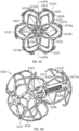
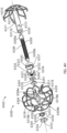
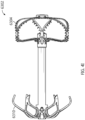
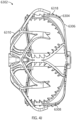
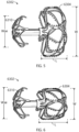
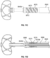
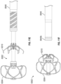
- Figures 3A-3C show another arrangement of a treatment device 6100 having an implant 6102 having a contact member 6104, and retention element 6108, and securing element 6110.
- the implant device 6102 can have any of the components, features, or other details of any other treatment device arrangements or implant device arrangements disclosed herein, including without limitation any of the other arrangements of the treatment devices or systems 100, 140, 4000, 6000 or implant devices 102, 104, 4002, 6002 described herein, in any combination with any of the components, features, or details of the implant device 6102 shown in Figures 3A-3C .
- any components, features, or other details of any of the other treatment device arrangements or implant device arrangements disclosed herein can have any of the components, features, or other details of any arrangements of the implant device 6102 disclosed herein in any combination with any of the components, features, or details of the other arrangements of the treatment device and/or implant device disclosed herein.
- the implant can be configured so that rotating the contact member 90° or approximately 90°, or from 60° or approximately 60° to 100° or approximately 100°, or from 70° or approximately 70° to 90° or approximately 90° from a first or initial position of the contact member can cause the contact member to contact and rotate at least an end portion of the tissue of the left atrial appendage (in some arrangements, for example and without limitation, without forming any overlaps or folds or without forming a significant number of overlaps or folds in the tissue of the left atrial appendage around the contact member) and so that rotating the contact member from 90° or approximately 90° to 180° or approximately 180°, or from between 60° or approximately 60° and 100° or approximately 100° to between 160° or approximately 160° and 200° or approximately 200°, will cause the tissue of the left atrial appendage to twist around the implant at least between the contact member and the securing element.
- the implant can be configured so that rotating the contact member past 180° or past approximately 180°, or past between 160° or approximately 160° to 200° or approximately 200°, can cause the tissue of the left atrial appendage to continue to twist and constrict around the implant mainly between the contact member and the securing element.
- the tissue can form one or more helical patterns of tissue which can present one or more potential leak channels.
- This potential "folding" of the tissue is illustrated in Figure 91, as discussed above.
- the helical patterns can present leak channels after the wrapped tissue has been collapsed in an axial direction, which can cause the tissue to loosen around the outside surface of the implant.
- the procedure can include all or any of the following steps, in combination with any of the other steps or procedures disclosed herein.
- the contact member After the contact member has been advanced axially to the desired position within the LAA, the contact member can be rotated in a first direction by a first predetermined angle. For some arrangements, this can be done by rotating a second dial 8084 on the handle of the delivery catheter.
- the first predetermined angle can be greater than or equal to 180 degrees, or greater than approximately 180 degrees, or can be greater than or equal to 180 degrees, or greater than approximately 180 degrees, or can be 270 degrees, approximately 270 degrees, from 200 degrees or less than 200 degrees to 330 degrees or more than 330 degrees, from 230 degrees to 300 degrees, from 250 degrees to 290 degrees, or any value or range of values in any of the foregoing ranges.
- the user can then proximally withdraw (e.g., pull back) the contact member 6304 by a first predetermined distance.
- the predetermined distance can be greater than or equal to 0.5 cm, or can be 1 cm, approximately 1 cm, from 0.25 cm to 1.75 cm, from 0.5 cm to 1.5 cm, from 0.75 cm to 1.25 cm, or any value or range of values in any of the foregoing ranges.
- the contact member can then be rotated in the first direction by a second predetermined angle.
- the second predetermined angle can be greater than or equal to 15 degrees, or can be greater than or equal to 30 degrees, or can be 65 degrees, approximately 65 degrees, from 30 degrees or less than 30 degrees to 90 degrees or more than 90 degrees, from 45 degrees to 150 degrees, from 30 degrees to 120 degrees, from 30 degrees to 90 degrees, or any value or range of values in any of the foregoing ranges.
- the securing element can be deployed and advanced toward the contact member.
- the contact member can then be rotated in the first direction by a third predetermined angle.
- the third predetermined angle can be 30 degrees, approximately 30 degrees, from 15 degrees or less than 15 degrees to 60 degrees or more than 60 degrees, from 15 degrees to 100 degrees, from 15 degrees to 60 degrees, from 15 degrees to 45 degrees, or any value or range of values in any of the foregoing ranges.
- the securing element can be deployed and advanced toward the contact member.
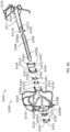
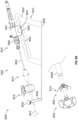
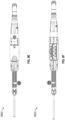
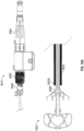
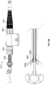
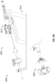
- Figure 8A shows an arrangement of a system 8000 for closing or occluding an LAA including an arrangement of a delivery system 8002 and an arrangement of an implant 8004.
- Figure 8B shows the arrangement of the delivery system 8002 shown in Figure 8A , including additional components for saline and contrast media injection, etc.
- the implant 8004 can be the same as or can have any combination of the features as any other arrangements of the implant disclosed herein, including without limitation implant 6102, 6302.
- the arrangement of the implant 6302 is illustrated in Figure 8A .
- the delivery system 8002 can include a catheter device 8010 and a support stand 8012.
- the delivery system 8002 can include a guide catheter 8014 and a dilator.
- the guide catheter can optionally include a steerable sheath and the delivery system 8002 can optionally include a steering device 8016 having a steering knob 8020 to steer a steerable sheath.
- the delivery system can include a nonsteerable guide catheter.
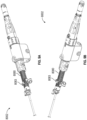
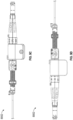
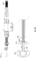
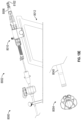
- Figures 9A-9H shows a portion of an arrangement of a delivery catheter 8002 that can be used with any arrangements of the implant disclosed herein.
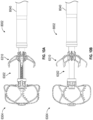
- Figures 10A-10C show a side view of the arrangement of the implant 6304 and distal end portion of the delivery catheter 8002, showing the outer sheath 8040 partially withdrawn and the contact member 6304 and the securing element 6310 each in an expanded state.
- the support stand 8012 can be positioned on a support surface, such as a bed or table, or can be positioned on a patient's body.
- the support stand 8012 can have a low slip surface on the bottom thereof, or can be positioned on a low slip material or surface such as a low-slip mat.
- the support stand 8012 can be used to removably support the delivery catheter 8010 (also referred to herein as a procedure catheter).
- Some arrangements of the support stand 8012 can include a base portion 8030, a first support portion 8032 having a slot 8033 therein, and a second support 8034 having a first locking element 8038 coupled therewith.
- Some arrangements of the support stand 8012 can have a scale used to measure or provide a measurement reference to a user of the system to determine how far the delivery catheter 8002 is moved along the slot 8033.
- the scale can provide millimeter and/or centimeter markings. For example and without limitation, this can assist the user in determining how far the implant is being moved relative to the user's anatomy during the procedure.
- the delivery catheter 8010 can have a clamp element 8041 having a tab or projection 8043 extending therefrom that is sized and configured to extend into the slot 8033 to help maintain an alignment of the delivery catheter 8010 to the first support portion 8032.
- the second support portion 8034 can be configured to support the guide catheter and dilator, and the first locking element 8038 can be selectively adjusted or tightened to secure a guide sheath of the guide catheter in a desired axial and/or rotational position after the guide sheath has been advanced to the target location using the steering device 8016.
- a guidewire e.g., a 0.035 in guidewire
- an introducer e.g., a 6 - 8 Fr introducer
- the guidewire and dilator can be advanced into the left atrium.
- An accepted or suitable transeptal procedure can be performed to achieve transeptal access.
- the steerable guide catheter 8014 can be advanced over the guidewire and supported by or coupled with the second support 8034.
- the metal tubing of the guide catheter 8014 can be secured to the second support 8034.
- a second locking element 8039 can be used to secure the guide catheter 8014 in the desired position relative to the guide catheter 8014 and the support stand 8012. With the dilator removed, a distal end of the outer sheath 8040 of the delivery catheter 8010 can be inserted into the guide sheath and advanced to the target location.
- Figure 8 illustrates this system after the outer sheath 8040 of the delivery catheter 8010 has been advanced into the guide catheter 8014.
- Angiograms or other suitable imaging techniques can be performed at any step in the process for baseline purposes and for visualization during the procedure.
- the outer sheath 8040 of the delivery catheter 8010 can be advanced and withdrawn axially relative to the guide sheath 8015 by sliding the delivery catheter 8010 distally and proximally, respectively, along the slot 8033 in the first support portion 8032 of the support stand 8012. By distally translating the delivery catheter 8010 toward the guide catheter 8014, the outer sheath 8040 of the delivery catheter 8010 can be advanced past a distal end of the guide sheath 8015.
- Figure 8 shows the implant 8004 after the implant 8004 has been advanced past a distal end 8040b of the outer sheath 8040.
- the contact member 6304 and/or the securing element 6310 of the implant 6302 can self-expand, depending on how far the outer sheath 8040 is withdrawn relative to the implant 6302.
- the outer sheath 8040 can be advanced or withdrawn by rotating a first dial 8060 of the delivery catheter 8010 in either a first direction (e.g., clockwise) or a second direction (e.g., counterclockwise), respectively.
- the contact member 6304 and/or the securing element 6310 of the implant 6302 can be advanced past a distal end 8040b of the outer sheath 8040 by distally advancing the implant 6302 relative to the outer sheath 8040.
- Figure 8 shows both the contact member 6302 and the securing element 6304 advanced past the distal end 8040b of the outer sheath 8040 and in an expanded state.
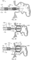
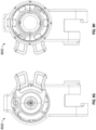
- Figure 12A illustrates the delivery system 8002 and the implant 6302, showing the outer sheath 8040 and the first dial 8060 which is rotationally coupled with the outer sheath 8040, in solid black shading.
- the delivery system 8002 can be configured such that a rotation of the first dial 8060 in a first direction (e.g., clockwise) can cause a threaded connector 8080 that can be coupled with the outer sheath 8040 to thread into a threaded opening in the first dial 8060 (e.g., moving the threaded connector 8080 from a first position as shown in Figure 13A to a second position as shown in Figure 13B ), thereby causing the outer sheath 8040 to move in the proximal direction.
- a rotation of the first dial 8060 in a first direction e.g., clockwise
- a threaded connector 8080 can be coupled with the outer sheath 8040 to thread into a threaded opening in the first dial 8060 (e.g., moving the threaded connector 8080
- the delivery system 8002 can be configured such that a rotation of the first dial 8060 in a second direction (e.g., counterclockwise) can cause a threaded connector 8080 that can be coupled with the outer sheath 8040 to thread out of the opening in the first dial 8060, thereby causing the outer sheath 8040 to move in the distal direction.
- This movement of the outer sheath 8040 can result in the distal end 8040b of the outer sheath 8040 moving relative to the implant 6302 to unrestrain the implant 6302.
- the delivery system 8002 can be configured to selectively limit an amount of rotation of the first dial 8060 relative to the threaded connector 8080. This can be done to inhibit (e.g., prevent) the user from inadvertently releasing the securing element 6310 from the outer sheath 8040 before the user is ready to.
- some arrangements of the delivery system 8002 can have a stop element (e.g., a clip) 8083 that can be removably coupled with the threaded connector 8080 at any desired position on the threaded connector 8080.
- the stop element 8083 can be coupled with the threaded connector 8080 at a position such that, when the stop element 8083 abuts a distal end of the first dial 8060, the first dial 8060 is inhibited (e.g., prevented) from rotating further in the direction that would cause the threaded connector 8080 to thread into the first dial 8060, thereby preventing further retraction of the outer sheath 8040 until the clip is moved distally or, more commonly, removed from the outer sheath 8040.
- stop element 8083 positioned as shown in Figure 9A can abut the distal end of the first dial 8060 when the outer sheath 8040 is positioned as shown in Figure 11D (where the securing element 6310 is position completely or nearly completely within the outer sheath 8040).
- the stop element 8083 can be removed from the threaded connector 8080 to continue rotation of the first dial 8060 in the direction that causes further retraction of the outer sheath 8040, as shown in Figure 13C .
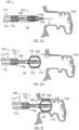
- the inner catheter 8086 can have one or more or a plurality of fins 8088 extending in a radial direction at a distal end 8086 of the inner catheter 8086.
- the fins 8088 can be configured to fit between the struts 6316 of the securing element 6310 at least when the securing element 6310 is in a restrained position within the outer sheath 8040. In this arrangement, the user can rotate the contact member and/or the securing element by rotating the second dial 8084 and, hence, the inner catheter 8086.
- the delivery system 8002 can have an angle gauge 8090 configured to rotate with the second dial 8084 so that a user can measure or track an angle of rotation of the second dial 8084. This can provide visual feedback to the user of generally how much the implant is being rotated during the procedure.
- the angle gauge 8090 can be configured to be adjustable or selectively rotatable relative to the second dial 8084.
- the user can disengage the coupling mechanism that selectively rotationally couples the angle gauge 8090 to the second dial 8084 so that the user can rotate the angle gauge 8090 relative to the second dial 8084 - e.g., to reset the angle gauge 8090 to a zero reading relative to an indicator on the delivery system 8002.
- the coupling mechanism can be a ball and detent or detents, or a plurality of balls and detents, that can be configured to bias the angle gauge 8090 to be rotationally coupled with the second dial 8084 but can be overcome by exerting a threshold torque on the angle gauge 8090 relative to the second dial 8084.
- the angle gauge 8090 can have readings at 45 degrees, or 30 degrees, or 15 degrees.
- the optional ball and detent mechanism can be configured to have a detent every 45 degrees, or 30 degrees, or 15 degrees that can be sized and configured to receive the ball so that the user can selectively rotate the angle gauge 8090 relative to the second dial 8084 and then recouple the angle gauge 8090 to the second dial 8084 at such increment (e.g., at 45 degrees, or 30 degrees, or 15 degrees).
- Other selective rotational coupling mechanisms can also be used to bias or selectively rotationally couple the angle gauge 8090 to the second dial 8084.
Landscapes
- Health & Medical Sciences (AREA)
- Life Sciences & Earth Sciences (AREA)
- Surgery (AREA)
- Engineering & Computer Science (AREA)
- Veterinary Medicine (AREA)
- Public Health (AREA)
- General Health & Medical Sciences (AREA)
- Biomedical Technology (AREA)
- Heart & Thoracic Surgery (AREA)
- Animal Behavior & Ethology (AREA)
- Molecular Biology (AREA)
- Medical Informatics (AREA)
- Nuclear Medicine, Radiotherapy & Molecular Imaging (AREA)
- Vascular Medicine (AREA)
- Reproductive Health (AREA)
- Cardiology (AREA)
- Anesthesiology (AREA)
- Hematology (AREA)
- Oral & Maxillofacial Surgery (AREA)
- Pathology (AREA)
- Robotics (AREA)
- Prostheses (AREA)
- Surgical Instruments (AREA)
Applications Claiming Priority (4)
| Application Number | Priority Date | Filing Date | Title |
|---|---|---|---|
| US202263298928P | 2022-01-12 | 2022-01-12 | |
| US202363479171P | 2023-01-09 | 2023-01-09 | |
| PCT/US2023/060504 WO2023137343A1 (en) | 2022-01-12 | 2023-01-11 | Devices, systems, and methods for treating the left atrial appendage |
| EP23704661.0A EP4463082A1 (de) | 2022-01-12 | 2023-01-11 | Vorrichtungen, systeme und verfahren zur behandlung des linken vorhofanhangs |
Related Parent Applications (1)
| Application Number | Title | Priority Date | Filing Date |
|---|---|---|---|
| EP23704661.0A Division EP4463082A1 (de) | 2022-01-12 | 2023-01-11 | Vorrichtungen, systeme und verfahren zur behandlung des linken vorhofanhangs |
Publications (2)
| Publication Number | Publication Date |
|---|---|
| EP4582033A2 true EP4582033A2 (de) | 2025-07-09 |
| EP4582033A3 EP4582033A3 (de) | 2025-10-22 |
Family
ID=85222368
Family Applications (2)
| Application Number | Title | Priority Date | Filing Date |
|---|---|---|---|
| EP23704661.0A Pending EP4463082A1 (de) | 2022-01-12 | 2023-01-11 | Vorrichtungen, systeme und verfahren zur behandlung des linken vorhofanhangs |
| EP25177737.1A Pending EP4582033A3 (de) | 2022-01-12 | 2023-01-11 | Vorrichtungen, systeme und verfahren zur behandlung des linken vorhofanhangs |
Family Applications Before (1)
| Application Number | Title | Priority Date | Filing Date |
|---|---|---|---|
| EP23704661.0A Pending EP4463082A1 (de) | 2022-01-12 | 2023-01-11 | Vorrichtungen, systeme und verfahren zur behandlung des linken vorhofanhangs |
Country Status (5)
| Country | Link |
|---|---|
| US (5) | US20230263531A1 (de) |
| EP (2) | EP4463082A1 (de) |
| JP (1) | JP2025502224A (de) |
| IL (1) | IL314230A (de) |
| WO (1) | WO2023137343A1 (de) |
Families Citing this family (6)
| Publication number | Priority date | Publication date | Assignee | Title |
|---|---|---|---|---|
| US11399842B2 (en) | 2013-03-13 | 2022-08-02 | Conformal Medical, Inc. | Devices and methods for excluding the left atrial appendage |
| US11426172B2 (en) | 2016-10-27 | 2022-08-30 | Conformal Medical, Inc. | Devices and methods for excluding the left atrial appendage |
| US11026695B2 (en) | 2016-10-27 | 2021-06-08 | Conformal Medical, Inc. | Devices and methods for excluding the left atrial appendage |
| US12144508B2 (en) | 2019-02-08 | 2024-11-19 | Conformal Medical, Inc. | Devices and methods for excluding the left atrial appendage |
| WO2021194964A1 (en) | 2020-03-24 | 2021-09-30 | Laminar, Inc. | Devices, systems, and methods for occluding cavities within the body |
| WO2025255201A1 (en) * | 2024-06-05 | 2025-12-11 | Boston Scientific Scimed, Inc. | Atraumatic implantation and closure of reconstructive laac device for safety and efficacy |
Family Cites Families (6)
| Publication number | Priority date | Publication date | Assignee | Title |
|---|---|---|---|---|
| US8545553B2 (en) * | 2009-05-04 | 2013-10-01 | Valtech Cardio, Ltd. | Over-wire rotation tool |
| US9351716B2 (en) * | 2009-06-17 | 2016-05-31 | Coherex Medical, Inc. | Medical device and delivery system for modification of left atrial appendage and methods thereof |
| EP3342354B1 (de) * | 2011-11-08 | 2021-03-03 | Boston Scientific Scimed, Inc. | Griffanordnung für eine vorrichtung zur okklusion des linken atriumappendix |
| JP6964082B2 (ja) * | 2016-09-16 | 2021-11-10 | テルモ株式会社 | 医療デバイス |
| CN113873957B (zh) * | 2019-03-25 | 2025-06-24 | 拉米纳公司 | 用于处理左心耳的装置和系统 |
| US12186188B2 (en) * | 2019-05-01 | 2025-01-07 | Twelve, Inc. | Support devices for transcatheter delivery system handles |
-
2023
- 2023-01-11 IL IL314230A patent/IL314230A/en unknown
- 2023-01-11 EP EP23704661.0A patent/EP4463082A1/de active Pending
- 2023-01-11 JP JP2024541854A patent/JP2025502224A/ja active Pending
- 2023-01-11 WO PCT/US2023/060504 patent/WO2023137343A1/en not_active Ceased
- 2023-01-11 EP EP25177737.1A patent/EP4582033A3/de active Pending
- 2023-01-11 US US18/153,311 patent/US20230263531A1/en active Pending
-
2025
- 2025-04-18 US US19/182,738 patent/US20250241651A1/en active Pending
- 2025-04-18 US US19/182,756 patent/US20250241653A1/en active Pending
- 2025-04-18 US US19/182,752 patent/US20250241652A1/en active Pending
- 2025-04-18 US US19/182,725 patent/US20250241650A1/en active Pending
Also Published As
| Publication number | Publication date |
|---|---|
| EP4582033A3 (de) | 2025-10-22 |
| US20250241653A1 (en) | 2025-07-31 |
| WO2023137343A1 (en) | 2023-07-20 |
| EP4463082A1 (de) | 2024-11-20 |
| IL314230A (en) | 2024-09-01 |
| US20250241651A1 (en) | 2025-07-31 |
| JP2025502224A (ja) | 2025-01-24 |
| US20250241650A1 (en) | 2025-07-31 |
| US20230263531A1 (en) | 2023-08-24 |
| US20250241652A1 (en) | 2025-07-31 |
Similar Documents
| Publication | Publication Date | Title |
|---|---|---|
| EP4582033A2 (de) | Vorrichtungen, systeme und verfahren zur behandlung des linken vorhofanhangs | |
| CN113873957B (zh) | 用于处理左心耳的装置和系统 | |
| US20250241706A1 (en) | Devices, systems, and methods for treating a tissue of the heart | |
| US20220022854A1 (en) | Devices, systems, and methods for treating the left atrial appendage | |
| JP7758265B2 (ja) | 体内の空洞を塞ぐためのデバイス、システム、および方法 | |
| JP2019516527A (ja) | 環状形成処置、関連装置及び方法 | |
| WO2017035381A1 (en) | Delivery device and methods of use of transapical delivery of replacement mitral valve | |
| US20250143713A1 (en) | Devices, systems, and methods for treating the left atrial appendage | |
| CN118843431A (zh) | 用于处理左心耳的装置、系统和方法 |
Legal Events
| Date | Code | Title | Description |
|---|---|---|---|
| PUAI | Public reference made under article 153(3) epc to a published international application that has entered the european phase |
Free format text: ORIGINAL CODE: 0009012 |
|
| STAA | Information on the status of an ep patent application or granted ep patent |
Free format text: STATUS: THE APPLICATION HAS BEEN PUBLISHED |
|
| AC | Divisional application: reference to earlier application |
Ref document number: 4463082 Country of ref document: EP Kind code of ref document: P |
|
| AK | Designated contracting states |
Kind code of ref document: A2 Designated state(s): AL AT BE BG CH CY CZ DE DK EE ES FI FR GB GR HR HU IE IS IT LI LT LU LV MC ME MK MT NL NO PL PT RO RS SE SI SK SM TR |
|
| PUAL | Search report despatched |
Free format text: ORIGINAL CODE: 0009013 |
|
| AK | Designated contracting states |
Kind code of ref document: A3 Designated state(s): AL AT BE BG CH CY CZ DE DK EE ES FI FR GB GR HR HU IE IS IT LI LT LU LV MC ME MK MT NL NO PL PT RO RS SE SI SK SM TR |
|
| RIC1 | Information provided on ipc code assigned before grant |
Ipc: A61B 17/12 20060101AFI20250918BHEP |