EP4582029A2 - Medizinische vorrichtung, systeme zur automatischen läsionsbeurteilung - Google Patents
Medizinische vorrichtung, systeme zur automatischen läsionsbeurteilung Download PDFInfo
- Publication number
- EP4582029A2 EP4582029A2 EP25172315.1A EP25172315A EP4582029A2 EP 4582029 A2 EP4582029 A2 EP 4582029A2 EP 25172315 A EP25172315 A EP 25172315A EP 4582029 A2 EP4582029 A2 EP 4582029A2
- Authority
- EP
- European Patent Office
- Prior art keywords
- processor
- identification
- blood vessel
- longitudinal section
- stent
- Prior art date
- Legal status (The legal status is an assumption and is not a legal conclusion. Google has not performed a legal analysis and makes no representation as to the accuracy of the status listed.)
- Pending
Links
Images


Classifications
-
- A—HUMAN NECESSITIES
- A61—MEDICAL OR VETERINARY SCIENCE; HYGIENE
- A61B—DIAGNOSIS; SURGERY; IDENTIFICATION
- A61B8/00—Diagnosis using ultrasonic, sonic or infrasonic waves
- A61B8/12—Diagnosis using ultrasonic, sonic or infrasonic waves in body cavities or body tracts, e.g. by using catheters
-
- A—HUMAN NECESSITIES
- A61—MEDICAL OR VETERINARY SCIENCE; HYGIENE
- A61B—DIAGNOSIS; SURGERY; IDENTIFICATION
- A61B5/00—Measuring for diagnostic purposes; Identification of persons
- A61B5/02—Detecting, measuring or recording for evaluating the cardiovascular system, e.g. pulse, heart rate, blood pressure or blood flow
- A61B5/02007—Evaluating blood vessel condition, e.g. elasticity, compliance
-
- A—HUMAN NECESSITIES
- A61—MEDICAL OR VETERINARY SCIENCE; HYGIENE
- A61B—DIAGNOSIS; SURGERY; IDENTIFICATION
- A61B8/00—Diagnosis using ultrasonic, sonic or infrasonic waves
- A61B8/44—Constructional features of the ultrasonic, sonic or infrasonic diagnostic device
- A61B8/4444—Constructional features of the ultrasonic, sonic or infrasonic diagnostic device related to the probe
- A61B8/445—Details of catheter construction
-
- A—HUMAN NECESSITIES
- A61—MEDICAL OR VETERINARY SCIENCE; HYGIENE
- A61B—DIAGNOSIS; SURGERY; IDENTIFICATION
- A61B8/00—Diagnosis using ultrasonic, sonic or infrasonic waves
- A61B8/46—Ultrasonic, sonic or infrasonic diagnostic devices with special arrangements for interfacing with the operator or the patient
- A61B8/461—Displaying means of special interest
- A61B8/463—Displaying means of special interest characterised by displaying multiple images or images and diagnostic data on one display
-
- A—HUMAN NECESSITIES
- A61—MEDICAL OR VETERINARY SCIENCE; HYGIENE
- A61B—DIAGNOSIS; SURGERY; IDENTIFICATION
- A61B8/00—Diagnosis using ultrasonic, sonic or infrasonic waves
- A61B8/52—Devices using data or image processing specially adapted for diagnosis using ultrasonic, sonic or infrasonic waves
- A61B8/5215—Devices using data or image processing specially adapted for diagnosis using ultrasonic, sonic or infrasonic waves involving processing of medical diagnostic data
- A61B8/5223—Devices using data or image processing specially adapted for diagnosis using ultrasonic, sonic or infrasonic waves involving processing of medical diagnostic data for extracting a diagnostic or physiological parameter from medical diagnostic data
-
- A—HUMAN NECESSITIES
- A61—MEDICAL OR VETERINARY SCIENCE; HYGIENE
- A61B—DIAGNOSIS; SURGERY; IDENTIFICATION
- A61B5/00—Measuring for diagnostic purposes; Identification of persons
- A61B5/0059—Measuring for diagnostic purposes; Identification of persons using light, e.g. diagnosis by transillumination, diascopy, fluorescence
- A61B5/0082—Measuring for diagnostic purposes; Identification of persons using light, e.g. diagnosis by transillumination, diascopy, fluorescence adapted for particular medical purposes
- A61B5/0084—Measuring for diagnostic purposes; Identification of persons using light, e.g. diagnosis by transillumination, diascopy, fluorescence adapted for particular medical purposes for introduction into the body, e.g. by catheters
Definitions
- the present disclosure pertains to medical devices and/or medical device systems. More particularly, the present disclosure pertains to medical device systems for automatic lesion assessment.
- intracorporeal medical devices have been developed for medical use, for example, intravascular use. Some of these devices include guidewires, catheters, and the like. These devices are manufactured by any one of a variety of different manufacturing methods and may be used according to any one of a variety of methods. Of the known medical devices and methods, each has certain advantages and disadvantages. There is an ongoing need to provide alternative medical devices as well as alternative methods for manufacturing and using medical devices.
- An example intravascular imaging system comprises: a catheter including an imaging device; a processor coupled to the catheter, the processor configured to process imaging data received from the imaging device; wherein the processor is configured to generate a longitudinal section view of a blood vessel from the imaging data received from the imaging device; wherein the processor is configured to identify a minimum lumen area along the longitudinal section view of the blood vessel, a distal reference point, and a proximal reference; and a display unit coupled to the processor, the display unit being configured to show a display including the longitudinal section view of the blood vessel.
- the display includes an indicator of the minimum lumen area.
- the indicator of the minimum lumen area is movable along the longitudinal section view of the blood vessel by a user.
- the display includes an indicator of the distal reference point.
- the indicator of the distal reference point is movable along the longitudinal section view of the blood vessel by a user.
- the display includes an indicator of the proximal reference point.
- the indicator of the proximal reference point is movable along the longitudinal section view of the blood vessel by a user.
- the processor is configured to identify a second minimum lumen area along the longitudinal section view of the blood vessel.
- the processor is configured to identify a secondary reference point along the longitudinal section view of the blood vessel.
- the intravascular imaging system comprises: an imaging catheter; a processor coupled to the catheter, the processor configured to process imaging data received from the imaging catheter; wherein the processor is configured to generate a longitudinal section view of a blood vessel from the imaging data; wherein the processor is configured to identify a minimum lumen area position along the longitudinal section view of the blood vessel, a distal reference point disposed distal of the minimum lumen area position, and a proximal reference disposed proximal of the minimum lumen area position; a display unit coupled to the processor, the display unit being configured to show a display; wherein the display includes the longitudinal section view of the blood vessel; and wherein the display includes an indicator of the minimum lumen area position, an indicator of the distal reference point, and an indicator of the proximal reference point along the longitudinal section view of the blood vessel.
- the indicator of the minimum lumen area position is movable along the longitudinal section view of the blood vessel by a user.
- the indicator of the distal reference point is movable along the longitudinal section view of the blood vessel by a user.
- the indicator of the proximal reference point is movable along the longitudinal section view of the blood vessel by a user.
- the processor is configured to identify a secondary reference point along the longitudinal section view of the blood vessel.
- a method for processing imaging data comprises: obtaining imaging data from an imaging catheter; processing the imaging data with a processor to generate a longitudinal section view of a blood vessel; wherein processing the imaging data includes identifying a minimum lumen area position of the blood vessel along the longitudinal section view of the blood vessel, identifying a distal reference point of the blood vessel along the longitudinal section view of the blood vessel, and identifying a proximal reference point of the blood vessel along the longitudinal section view of the blood vessel; modifying one or more of the minimum lumen area position, the distal reference point, and the proximal reference point to a secondary position; and affirming the secondary position.
- processing the imaging data with a processor to generate a longitudinal section view of a blood vessel includes processing the imaging data prior to treating the blood vessel with a stent.
- processing the imaging data with a processor to generates a longitudinal section view of a blood vessel includes processing the imaging data after treating the blood vessel with a stent.
- the intravascular imaging system comprises: a catheter including an imaging device; a processor coupled to the catheter, the processor configured to process imaging data received from the imaging device; wherein the processor is configured to generate a longitudinal section view of a blood vessel from the imaging data received from the imaging device; wherein the processor is configured to identify a minimum stent area along the longitudinal section view of the blood vessel, a distal reference point, and a proximal reference; and a display unit coupled to the processor, the display unit being configured to show a display including the longitudinal section view of the blood vessel.
- the display includes an indicator of the minimum stent area.
- the indicator of the distal reference point is movable along the longitudinal section view of the blood vessel by a user.
- the display includes an indicator of the proximal reference point.
- the indicator of the proximal reference point is movable along the longitudinal section view of the blood vessel by a user.
- the processor is configured to identify a secondary reference point along the longitudinal section view of the blood vessel.
- the intravascular imaging system comprises: an imaging catheter; a processor coupled to the catheter, the processor configured to process imaging data received from the imaging catheter; wherein the processor is configured to generate a longitudinal section view of a blood vessel from the imaging data; wherein the processor is configured to identify a minimum stent area position along the longitudinal section view of the blood vessel, a distal reference point disposed distal of the minimum stent area position, and a proximal reference disposed proximal of the minimum stent area position; a display unit coupled to the processor, the display unit being configured to show a display; wherein the display includes the longitudinal section view of the blood vessel; and wherein the display includes an indicator of the minimum stent area position, an indicator of the distal reference point, and an indicator of the proximal reference point along the longitudinal section view of the blood vessel.
- the indicator of the minimum stent area position is movable along the longitudinal section view of the blood vessel by a user.
- the indicator of the distal reference point is movable along the longitudinal section view of the blood vessel by a user.
- the indicator of the proximal reference point is movable along the longitudinal section view of the blood vessel by a user.
- the processor is configured to identify a secondary reference point along the longitudinal section view of the blood vessel.
- modifying one or more of the minimum stent area position, the distal reference point, and the proximal reference point to a secondary position includes translating a bookmark corresponding to the minimum stent area position, the distal reference point, or the proximal reference point along the longitudinal section view of the blood vessel to the secondary position.
- processing the imaging data with a processor to generate a longitudinal section view of a blood vessel includes identifying a secondary reference point.
- processing the imaging data with a processor to generate a longitudinal section view of a blood vessel includes processing the imaging data prior to treating the blood vessel with a stent.
- processing the imaging data with a processor to generates a longitudinal section view of a blood vessel includes processing the imaging data after treating the blood vessel with a stent.
- the suitable percent stent expansion is determined from the minimum stent area.
- the suitable percent stent expansion is determined by comparing the minimum stent area to the diameter of the blood vessel at the proximal reference point.
- the suitable percent stent expansion is determined by comparing the minimum stent area to the diameter of the blood vessel at the distal reference point.
- the suitable percent stent expansion is determined by comparing the minimum stent area to the average of the diameters of the blood vessel at the proximal and distal reference points.
- the intravascular imaging system comprises: a catheter including an imaging device; a processor coupled to the catheter, the processor configured to process imaging data received from the imaging device; wherein the processor is configured to generate a vessel profile view of a blood vessel from the imaging data received from the imaging device; wherein the processor is configured to identify a minimum stent area along the vessel profile view of the blood vessel, a distal reference point, and a proximal reference; and a display unit coupled to the processor, the display unit being configured to show a display including the vessel view of the blood vessel.
- the suitable percent stent expansion is determined from the minimum stent area.
- the suitable percent stent expansion is determined by comparing the minimum stent area to the diameter of the blood vessel at the proximal reference point.
- the suitable percent stent expansion is determined by comparing the minimum stent area to the diameter of the blood vessel at the distal reference point.
- the suitable percent stent expansion is determined by comparing the minimum stent area to the average of the diameters of the blood vessel at the proximal and distal reference points.
- references in the specification to "an embodiment”, “some embodiments”, “other embodiments”, etc. indicate that the embodiment described may include one or more particular features, structures, and/or characteristics. However, such recitations do not necessarily mean that all embodiments include the particular features, structures, and/or characteristics. Additionally, when particular features, structures, and/or characteristics are described in connection with one embodiment, it should be understood that such features, structures, and/or characteristics may also be used connection with other embodiments whether or not explicitly described unless clearly stated to the contrary.
- Intravascular imaging devices insertable into patients have proven diagnostic capabilities for a variety of diseases and disorders.
- intravascular ultrasound (“IVUS”) imaging systems and/or optical coherence tomography (“OCT”) imaging systems may be used as an imaging modality for diagnosing blocked blood vessels and providing information to aid medical practitioners in selecting and placing stents and other devices to restore or increase blood flow.
- IVUS/OCT imaging systems may also be used to diagnose atheromatous plaque build-up at particular locations within blood vessels.
- IVUS/OCT imaging systems may also be used to determine the existence of an intravascular obstruction or stenosis, as well as the nature and degree of the obstruction or stenosis.
- IVUS/OCT imaging systems may also be used to visualize segments of a vascular system that may be difficult to visualize using other intravascular imaging techniques, such as angiography, due to, for example, movement (e.g., a beating heart) or obstruction by one or more structures (e.g., one or more blood vessels not desired to be imaged). IVUS/OCT imaging systems may also be used to monitor or assess ongoing intravascular treatments, such as angiography and stent placement in real (or almost real) time. Moreover, IVUS/OCT imaging systems may be used to monitor one or more heart chambers.
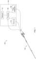
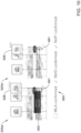
- FIG. 1 illustrates schematically an example intravascular imaging system 100.
- the intravascular imaging system 100 takes the form of an IVUS imaging system.
- the IVUS imaging system 100 includes a catheter 102 that is coupleable to a processing unit or control module 104.
- the control module 104 may include, for example, a processor 106, a pulse generator 108, a drive unit 110, and one or more displays or display units 112.
- the pulse generator 108 forms electric pulses that may be input to one or more transducers (312 in FIG. 3 ) disposed in the catheter 102.
- the term “display” may either refer to an electronic device (e.g., such as a monitor, etc.) used for the visual representation of data or to the visual representation of data itself.
- the term “display” may refer to a hardware device for displaying data or the term “display” may refer to the data displayed on the hardware device.
- Such terminology need not be strictly adhered to in this disclosure or in the art in general.
- One of skill in the art would be able to discern when the term “display” is referring to a hardware component and when the term “display” is referring to the visual/data component.
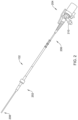
- FIG. 2 is a schematic side view of one embodiment of the catheter 102 of the IVUS imaging system (100 in FIG. 1 ).
- the catheter 102 includes an elongated member 202 and a hub 204.
- the elongated member 202 includes a proximal end 206 and a distal end 208.
- the proximal end 206 of the elongated member 202 is coupled to the catheter hub 204 and the distal end 208 of the elongated member is configured and arranged for percutaneous insertion into a patient.
- the catheter 102 may define at least one flush port, such as flush port 210.
- the flush port 210 may be defined in the hub 204.
- the hub 204 may be configured and arranged to couple to the control module (104 in FIG 1 ).
- the elongated member 202 and the hub 204 are formed as a unitary body. In other instances, the elongated member 202 and the catheter hub 204 are formed separately and subsequently assembled together.
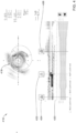
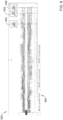
- FIG. 3 is a schematic perspective view of one embodiment of the distal end 208 of the elongated member 202 of the catheter 102.
- the elongated member 202 includes a sheath 302 with a longitudinal axis (e.g., a central longitudinal axis extending axially through the center of the sheath 302 and/or the catheter 102) and a lumen 304.
- An imaging core 306 is disposed in the lumen 304.
- the imaging core 306 includes an imaging device 308 coupled to a distal end of a driveshaft 310 that is rotatable either manually or using a computer-controlled drive mechanism.
- One or more transducers 312 may be mounted to the imaging device 308 and employed to transmit and receive acoustic signals.
- the sheath 302 may be formed from any flexible, biocompatible material suitable for insertion into a patient.
- suitable materials include, for example, polyethylene, polyurethane, plastic, spiral-cut stainless steel, nitinol hypotube, and the like or combinations thereof.
- an array of transducers 312 are mounted to the imaging device 308.
- a single transducer may be employed. Any suitable number of transducers 312 can be used. For example, there can be two, three, four, five, six, seven, eight, nine, ten, twelve, fifteen, sixteen, twenty, twenty-five, fifty, one hundred, five hundred, one thousand, or more transducers. As will be recognized, other numbers of transducers may also be used.
- the transducers 312 can be configured into any suitable arrangement including, for example, an annular arrangement, a rectangular arrangement, or the like.
- the one or more transducers 312 may be formed from materials capable of transforming applied electrical pulses to pressure distortions on the surface of the one or more transducers 312, and vice versa.
- suitable materials include piezoelectric ceramic materials, piezocomposite materials, piezoelectric plastics, barium titanates, lead zirconate titanates, lead metaniobates, polyvinylidene fluorides, and the like.
- Other transducer technologies include composite materials, single-crystal composites, and semiconductor devices (e.g., capacitive micromachined ultrasound transducers ("cMUT”), piezoelectric micromachined ultrasound transducers ("pMUT”), or the like).
- the pressure distortions on the surface of the one or more transducers 312 form acoustic pulses of a frequency based on the resonant frequencies of the one or more transducers 312.
- the resonant frequencies of the one or more transducers 312 may be affected by the size, shape, and material used to form the one or more transducers 312.
- the one or more transducers 312 may be formed in any shape suitable for positioning within the catheter 102 and for propagating acoustic pulses of a desired frequency in one or more selected directions.
- transducers may be disc-shaped, block-shaped, rectangular-shaped, oval-shaped, and the like.
- the one or more transducers may be formed in the desired shape by any process including, for example, dicing, dice and fill, machining, microfabrication, and the like.
- each of the one or more transducers 312 may include a layer of piezoelectric material sandwiched between a matching layer and a conductive backing material formed from an acoustically absorbent material (e.g., an epoxy substrate with tungsten particles). During operation, the piezoelectric layer may be electrically excited to cause the emission of acoustic pulses.
- an acoustically absorbent material e.g., an epoxy substrate with tungsten particles.
- the one or more transducers 312 can be used to form a radial cross-sectional image of a surrounding space.
- the one or more transducers 312 may be used to form an image of the walls of the blood vessel and tissue surrounding the blood vessel.
- the imaging core 306 is rotated about the longitudinal axis of the catheter 102.
- the one or more transducers 312 emit acoustic signals in different radial directions (e.g., along different radial scan lines).
- the one or more transducers 312 can emit acoustic signals at regular (or irregular) increments, such as 256 radial scan lines per revolution, or the like. It will be understood that other numbers of radial scan lines can be emitted per revolution, instead.
- a portion of the emitted acoustic pulse is reflected back to the emitting transducer as an echo pulse.
- Each echo pulse that reaches a transducer with sufficient energy to be detected is transformed to an electrical signal in the receiving transducer.
- the one or more transformed electrical signals are transmitted to the control module (104 in FIG. 1 ) where the processor 106 processes the electrical-signal characteristics to form a displayable image of the imaged region based, at least in part, on a collection of information from each of the acoustic pulses transmitted and the echo pulses received.
- the rotation of the imaging core 306 is driven by the drive unit 110 disposed in the control module (104 in FIG. 1 ).
- the one or more transducers 312 are fixed in place and do not rotate.
- the driveshaft 310 may, instead, rotate a mirror that reflects acoustic signals to and from the fixed one or more transducers 312.
- a plurality of images can be formed that collectively form a radial cross-sectional image (e.g., a tomographic image) of a portion of the region surrounding the one or more transducers 312, such as the walls of a blood vessel of interest and tissue surrounding the blood vessel.
- the radial cross-sectional image can, optionally, be displayed on one or more display units 112.
- the at least one of the imaging core 306 can be either manually rotated or rotated using a computer-controlled mechanism.
- the imaging core 306 may also move longitudinally along the blood vessel within which the catheter 102 is inserted so that a plurality of cross-sectional images may be formed along a longitudinal length of the blood vessel.
- the one or more transducers 312 may be retracted (e.g., pulled back) along the longitudinal length of the catheter 102.
- the catheter 102 can include at least one telescoping section that can be retracted during pullback of the one or more transducers 312.
- the drive unit 110 drives the pullback of the imaging core 306 within the catheter 102.
- the drive unit 110 pullback distance of the imaging core can be any suitable distance including, for example, at least 5 cm, 10 cm, 15 cm, 20 cm, 25 cm, or more.
- the entire catheter 102 can be retracted during an imaging procedure either with or without the imaging core 306 moving longitudinally independently of the catheter 102.
- a stepper motor may, optionally, be used to pull back the imaging core 306.
- the stepper motor can pull back the imaging core 306 a short distance and stop long enough for the one or more transducers 306 to capture an image or series of images before pulling back the imaging core 306 another short distance and again capturing another image or series of images, and so on.
- the quality of an image produced at different depths from the one or more transducers 312 may be affected by one or more factors including, for example, bandwidth, transducer focus, beam pattern, as well as the frequency of the acoustic pulse.
- the frequency of the acoustic pulse output from the one or more transducers 312 may also affect the penetration depth of the acoustic pulse output from the one or more transducers 312. In general, as the frequency of an acoustic pulse is lowered, the depth of the penetration of the acoustic pulse within patient tissue increases. In some instances, the IVUS imaging system 100 operates within a frequency range of 5 MHz to 100 MHz.
- One or more conductors 314 can electrically couple the transducers 312 to the control module 104 (see, for example, FIG. 1 ). In which case, the one or more conductors 314 may extend along a longitudinal length of the rotatable driveshaft 310.
- the catheter 102 with one or more transducers 312 mounted to the distal end 208 of the imaging core 308 may be inserted percutaneously into a patient via an accessible blood vessel, such as the femoral artery, femoral vein, or jugular vein, at a site remote from the selected portion of the selected region, such as a blood vessel, to be imaged.
- the catheter 102 may then be advanced through the blood vessels of the patient to the selected imaging site, such as a portion of a selected blood vessel.
- An image or image frame can be generated each time one or more acoustic signals are output to surrounding tissue and one or more corresponding echo signals are received by the imager 308 and transmitted to the processor 106.
- an image or image frame can be a composite of scan lines from a full or partial rotation of the imaging core or device.
- a plurality (e.g., a sequence) of frames may be acquired over time during any type of movement of the imaging device 308.
- the frames can be acquired during rotation and pullback of the imaging device 308 along the target imaging location. It will be understood that frames may be acquired both with or without rotation and with or without pullback of the imaging device 308.
- frames may be acquired using other types of movement procedures in addition to, or in lieu of, at least one of rotation or pullback of the imaging device 308.
- the pullback when pullback is performed, the pullback may be at a constant rate, thus providing a tool for potential applications able to compute longitudinal vessel/plaque measurements.
- the imaging device 308 is pulled back at a constant rate of about 0.3-0.9 mm/s or about 0.5-.8 mm/s. In some instances, the imaging device 308 is pulled back at a constant rate of at least 0.3 mm/s. In some instances, the imaging device 308 is pulled back at a constant rate of at least 0.4 mm/s. In some instances, the imaging device 308 is pulled back at a constant rate of at least 0.5 mm/s. In some instances, the imaging device 308 is pulled back at a constant rate of at least 0.6 mm/s. In some instances, the imaging device 308 is pulled back at a constant rate of at least 0.7 mm/s. In some instances, the imaging device 308 is pulled back at a constant rate of at least 0.8 mm/s.
- the one or more acoustic signals are output to surrounding tissue at constant intervals of time.
- the one or more corresponding echo signals are received by the imager 308 and transmitted to the processor 106 at constant intervals of time.
- the resulting frames are generated at constant intervals of time.
- At least some conventional IVUS imaging systems display only a single (e.g., cross-sectional, longitudinal, or the like) image during, or after, an IVUS procedure, such as a pull-back procedure. It may, however, be useful to concurrently display, in real-time during the IVUS procedure (e.g., a pull-back procedure), at least two images, such as the most recently processed image and a previously-obtained image that has some particular or selected image characteristic (e.g., maximum or minimum lumen area or diameter).
- a single (e.g., cross-sectional, longitudinal, or the like) image during, or after, an IVUS procedure such as a pull-back procedure. It may, however, be useful to concurrently display, in real-time during the IVUS procedure (e.g., a pull-back procedure), at least two images, such as the most recently processed image and a previously-obtained image that has some particular or selected image characteristic (e.g., maximum or minimum lumen area or diameter).
- the output may be displayed on a display unit in a suitable format (e.g., graphically, numerically, as a real or schematic image, with words or symbols, etc.). In some instances, multiple images of an IVUS pullback or "run" may be analyzed.
- the output of this run analysis may include a lumen profile (e.g., including, for example, a longitudinal section or "long view"), a vessel profile (e.g., including, for example, a longitudinal section or "long view”), a representation (e.g., visualization or image, numerical visualization, graphical visualization, and/or the like) of the calcification length, the depiction/display of reference frames (e.g., such as the minimal lumen area or "MLA", the minimal stent area or "MSA”, or the like), a representation (e.g., visualization or image, numerical visualization, graphical visualization, and/or the like) of side branch location, a representation (e.g., visualization or image, numerical visualization, graphical visualization, and/or the like) of the distance between two frames of interest, a representation (e.g., visualization or image, numerical visualization, graphical visualization, and/or the like) of stent extension, combinations thereof, and/or the like.
- This may also include analyzing the images with
- FIG. 4 shows an example display 416, which may be displayed on the display/display unit 112.
- the display 416 includes a transverse cross-sectional image 418 of an example blood vessel and a longitudinal section image/display 420 of the blood vessel.
- the processor 106 may be configured to automatically identify a minimum lumen area (MLA) of the blood vessel and then output/display an indicator or bookmark corresponding to the MLA 422 along the longitudinal section display 420.
- MLA minimum lumen area
- This may include the use of a deep neural network (e.g., such as UNet deep neural network) and/or machine learning and/or artificial intelligence.
- the processor 106 may also be configured to identify a proximal reference point and a distal reference point.
- processor 106 may provide a reliable level of precision and accuracy when identifying the MLA, the distal reference point, and the proximal reference point, and/or identifying other features of a blood vessel, a clinician may still wish to review the locations of these points and, if desired, confirm and/or modify the location of these points.
- the selected indicator/bookmark 422, 424, 426 moves/translates along the longitudinal section display 420. It can be appreciated that each of the indicators 422, 424, 426 are independently movable along the longitudinal section display 420.
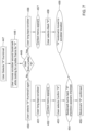
- the user may determine if a more desirable location has been located. If not, user may select the particular bookmark or indicator 422, 424, 426 (box 450), long tap/hold the scrubber (box 451), which causes a context menu to appear at box 452. Within the context menu, the user may confirm the location of the indicator (box 453), which makes the indicator/bookmark "hard” and a checkbox appears checked for that particular bookmark or indicator 422, 424, 426 (box 454). This confirms the particular bookmark or indicator 422, 424, 426 (box 455).
- the user may long tap/hold the scrubber (box 456) while the scrubber is at the alternative/secondary location, causing a context menu to appear (box 457).
- the user may select to mark the new location (box 458) and the particular bookmark or indicator 422, 424, 426 may be moved to the new/secondary/alternative location (box 459). This makes the indicator/bookmark "hard” and a checkbox appears checked for that particular bookmark or indicator 422, 424, 426 (box 454) and the particular bookmark or indicator 422, 424, 426 is then confirmed (box 455).
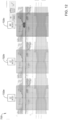
- FIGS. 8-11 show longitudinal section displays (e.g., similar to the longitudinal section display 420 in FIG. 4 ) at some example points along the processes described with reference to FIGS. 5-7 .
- FIG. 8 illustrates a longitudinal section display 520.
- "soft" indicators/bookmarks 522, 524, 526 are shown along the longitudinal section display 520, corresponding to box 432 in FIG. 5 and/or box 439 in FIG. 6 (noting that in a post-PCT run, the indicator 522 may be an indicator of MSA).
- a menu 460 showing that none of the indicators 522, 524, 526 are confirmed (e.g., by virtue of the checkbox next to the given label not being selected).
- FIG. 9 A process for adjusting/confirming a particular indicator is shown in FIG. 9 .
- the process includes adjusting/confirming the indicator 524 for the distal reference point (RefD).
- FIG. 9 three separate depictions of the longitudinal section display 520 are shown, namely depictions 520a, 520b, 520c.
- a user may select the indicator/bookmark 524 (e.g., box 447 in FIG. 7 ) by touching the scrubber 561 (e.g., when using a touch screen display, the user may use the finger or a suitable input device).
- the scrubber 561 may be moved (e.g., by translating the slider using a finger or suitable input device) to a new location (e.g., box 448 in FIG. 7 ) as shown in depiction 520b. If the user does not find the new location to be more desirable, the user may long tap/hold the scrubber 561 (e.g., box 451 in FIG. 7 ) and a context menu 562 may appear (box 452 in FIG. 7 ). The user may confirm the location (box 453 in FIG. 7 ) and the indicator/bookmark 524 then becomes "hard" (box 454 in FIG. 7 .) and may be confirmed by the check in the menu 560 (box 455 in FIG. 7 ).
- the process may be similarly carried out for another one of the indicators/bookmarks, in this example the indicator/bookmark 526 corresponding to the proximal reference point (RefP).
- the indicator/bookmark 526 corresponding to the proximal reference point (RefP).
- FIG. 10 two separate depictions of the longitudinal section display 520 are shown, namely depictions 520a, 520b.
- a user may select the indicator/bookmark 526 (e.g., box 447 in FIG. 7 ) by touching the scrubber 561.
- the scrubber 561 may be moved to a new location (e.g., box 448 in FIG. 7 ) as shown in depiction 520b.
- the user may long tap/hold the scrubber 561 (e.g., box 456 in FIG. 7 ) and a context menu 563 may appear (e.g., box 457 in FIG. 7 ).
- the user may mark the new location (box 458 in FIG. 7 ) and the indicator/bookmark 526 may be moved to the new location (box 459 in FIG. 7 ).
- the indicator/bookmark 526 may then become "hard” (box 454 in FIG. 7 .) and may be confirmed by the check in the menu 560 (box 455 in FIG. 7 ).
- FIG. 11 illustrates a longitudinal section display 620.
- the menu 660 shows that each of the indicators/bookmarks are confirmed by the check in the menu 660.
- the MLA indicator 622 may also display the diameter at the MLA 664, which may aid a clinician in determining a suitable stent diameter size to be used for an intervention.
- the distance between indicator 624 and indicator 626 is also shown with a bar 665. The bar may be labeled with the distance between the indicators 624, 626, which may help a clinician determine a suitable stent length that can be used to treat the lesion.
- the longitudinal section display 620 and/or other longitudinal section displays disclosed herein may also provide an indicator or graphic depicting percent stent expansion.
- the processor 106 may be capable of determining a desirable amount/percent of stent expansion suitable for treating the blood vessel based on the MSA alone.
- the processor 106 may compare the MSA to (a) the diameter of the blood vessel at the proximal reference point, (b) the diameter of the blood vessel at the proximal reference point, or (c) the mean or average of the diameters at the proximal and distal reference points.
- the indicator or graphic may be disposed adjacent to the longitudinal section display 620 indicating one or more of (a) desired percent stent expansion for a treatment based on MSA alone, (b) desired percent stent expansion for a treatment based on comparing MSA to the diameter of the blood vessel at the proximal reference point, (c) desired percent stent expansion for a treatment based on comparing MSA to the diameter of the blood vessel at the distal reference point, and/or (d) desired percent stent expansion for a treatment based on comparing MSA to the mean or average of the diameters of the blood vessel at the proximal and distal reference points.
Landscapes
- Health & Medical Sciences (AREA)
- Life Sciences & Earth Sciences (AREA)
- Engineering & Computer Science (AREA)
- Heart & Thoracic Surgery (AREA)
- Public Health (AREA)
- Veterinary Medicine (AREA)
- Biophysics (AREA)
- Pathology (AREA)
- Physics & Mathematics (AREA)
- Biomedical Technology (AREA)
- General Health & Medical Sciences (AREA)
- Medical Informatics (AREA)
- Molecular Biology (AREA)
- Surgery (AREA)
- Animal Behavior & Ethology (AREA)
- Nuclear Medicine, Radiotherapy & Molecular Imaging (AREA)
- Radiology & Medical Imaging (AREA)
- Physiology (AREA)
- Vascular Medicine (AREA)
- Cardiology (AREA)
- Computer Vision & Pattern Recognition (AREA)
- Ultra Sonic Daignosis Equipment (AREA)
- Endoscopes (AREA)
Applications Claiming Priority (3)
| Application Number | Priority Date | Filing Date | Title |
|---|---|---|---|
| US202163253881P | 2021-10-08 | 2021-10-08 | |
| PCT/US2022/045827 WO2023059754A1 (en) | 2021-10-08 | 2022-10-05 | Medical device systems for automatic lesion assessment |
| EP22809937.0A EP4398805A1 (de) | 2021-10-08 | 2022-10-05 | Medizinische vorrichtung, systeme zur automatischen läsionsbeurteilung |
Related Parent Applications (1)
| Application Number | Title | Priority Date | Filing Date |
|---|---|---|---|
| EP22809937.0A Division EP4398805A1 (de) | 2021-10-08 | 2022-10-05 | Medizinische vorrichtung, systeme zur automatischen läsionsbeurteilung |
Publications (2)
| Publication Number | Publication Date |
|---|---|
| EP4582029A2 true EP4582029A2 (de) | 2025-07-09 |
| EP4582029A3 EP4582029A3 (de) | 2025-09-10 |
Family
ID=84361614
Family Applications (2)
| Application Number | Title | Priority Date | Filing Date |
|---|---|---|---|
| EP22809937.0A Pending EP4398805A1 (de) | 2021-10-08 | 2022-10-05 | Medizinische vorrichtung, systeme zur automatischen läsionsbeurteilung |
| EP25172315.1A Pending EP4582029A3 (de) | 2021-10-08 | 2022-10-05 | Medizinische vorrichtung, systeme zur automatischen läsionsbeurteilung |
Family Applications Before (1)
| Application Number | Title | Priority Date | Filing Date |
|---|---|---|---|
| EP22809937.0A Pending EP4398805A1 (de) | 2021-10-08 | 2022-10-05 | Medizinische vorrichtung, systeme zur automatischen läsionsbeurteilung |
Country Status (5)
| Country | Link |
|---|---|
| US (1) | US20230112017A1 (de) |
| EP (2) | EP4398805A1 (de) |
| JP (2) | JP7743622B2 (de) |
| CN (1) | CN118450850A (de) |
| WO (1) | WO2023059754A1 (de) |
Citations (1)
| Publication number | Priority date | Publication date | Assignee | Title |
|---|---|---|---|---|
| WO2021062006A1 (en) | 2019-09-26 | 2021-04-01 | Boston Scientific Scimed, Inc. | Intravascular ultrasound imaging and calcium detection methods |
Family Cites Families (12)
| Publication number | Priority date | Publication date | Assignee | Title |
|---|---|---|---|---|
| EP2480124B1 (de) * | 2009-09-23 | 2017-11-22 | Lightlab Imaging, Inc. | Lumenmorphologie und vaskuläre widerstandsmessungdatensammelsysteme, vorrichtung und verfahren |
| JP2012200532A (ja) * | 2011-03-28 | 2012-10-22 | Terumo Corp | 画像診断装置及び表示方法 |
| EP4445837A3 (de) * | 2012-12-12 | 2024-12-25 | Lightlab Imaging, Inc. | Vorrichtung zur automatisierten bestimmung einer lumenkontur eines blutgefässes |
| US20150157295A1 (en) * | 2013-12-09 | 2015-06-11 | Qisda Corporation | Ultrasound system and pointer controller |
| EP3766079A1 (de) * | 2018-03-14 | 2021-01-20 | Koninklijke Philips N.V. | Bewertung von intravaskulären läsionen und stenteinführung in der medizinischen intraluminalen ultraschallbildgebung |
| EP3764915B1 (de) * | 2018-03-15 | 2025-07-16 | Koninklijke Philips N.V. | Bestimmung und visualisierung anatomischer landmarken für intraluminale läsionsbeurteilung und behandlungsplanung |
| US20200029932A1 (en) * | 2018-07-30 | 2020-01-30 | Koninklijke Philips N.V. | Systems, devices, and methods for displaying multiple intraluminal images in luminal assessment with medical imaging |
| US12440188B2 (en) * | 2018-10-26 | 2025-10-14 | Philips Image Guided Therapy Corporation | Graphical longitudinal display for intraluminal ultrasound imaging and associated devices, systems, and methods |
| EP4099910B1 (de) * | 2020-02-04 | 2025-05-07 | Koninklijke Philips N.V. | Automatische intraluminale abbildungsbasierte ziel- und referenzbildrahmenerfassung |
| WO2021199967A1 (ja) * | 2020-03-30 | 2021-10-07 | テルモ株式会社 | プログラム、情報処理方法、学習モデルの生成方法、学習モデルの再学習方法、および、情報処理システム |
| WO2022238058A1 (en) * | 2021-05-13 | 2022-11-17 | Koninklijke Philips N.V. | Preview of intraluminal ultrasound image along longitudinal view of body lumen |
| CN117295467A (zh) * | 2021-05-13 | 2023-12-26 | 皇家飞利浦有限公司 | 来自先前的管腔外成像、管腔内数据和共配准的管腔内治疗指导 |
-
2022
- 2022-10-05 CN CN202280080845.9A patent/CN118450850A/zh active Pending
- 2022-10-05 EP EP22809937.0A patent/EP4398805A1/de active Pending
- 2022-10-05 US US17/960,812 patent/US20230112017A1/en active Pending
- 2022-10-05 WO PCT/US2022/045827 patent/WO2023059754A1/en not_active Ceased
- 2022-10-05 JP JP2024520913A patent/JP7743622B2/ja active Active
- 2022-10-05 EP EP25172315.1A patent/EP4582029A3/de active Pending
-
2025
- 2025-09-10 JP JP2025149821A patent/JP2025175093A/ja active Pending
Patent Citations (1)
| Publication number | Priority date | Publication date | Assignee | Title |
|---|---|---|---|---|
| WO2021062006A1 (en) | 2019-09-26 | 2021-04-01 | Boston Scientific Scimed, Inc. | Intravascular ultrasound imaging and calcium detection methods |
Also Published As
| Publication number | Publication date |
|---|---|
| EP4398805A1 (de) | 2024-07-17 |
| JP7743622B2 (ja) | 2025-09-24 |
| JP2024536386A (ja) | 2024-10-04 |
| US20230112017A1 (en) | 2023-04-13 |
| WO2023059754A1 (en) | 2023-04-13 |
| JP2025175093A (ja) | 2025-11-28 |
| CN118450850A (zh) | 2024-08-06 |
| EP4582029A3 (de) | 2025-09-10 |
Similar Documents
| Publication | Publication Date | Title |
|---|---|---|
| US20230157672A1 (en) | Intravascular ultrasound imaging and calcium detection methods | |
| AU2014223201B2 (en) | Systems and methods for lumen border detection in intravascular ultrasound sequences | |
| EP4505946A2 (de) | Intravaskuläre ultraschallsysteme und katheter mit manueller rückzugsanordnung | |
| US20120130242A1 (en) | Systems and methods for concurrently displaying a plurality of images using an intravascular ultrasound imaging system | |
| US20120283569A1 (en) | Systems and methods for navigating and visualizing intravascular ultrasound sequences | |
| US20100249588A1 (en) | Systems and methods for making and using intravascular imaging systems with multiple pullback rates | |
| US20250114068A1 (en) | Intravascular imaging system with automated calcium analysis and treatment guidance | |
| US20230380806A1 (en) | Systems and methods for intravascular visualization | |
| EP4582029A2 (de) | Medizinische vorrichtung, systeme zur automatischen läsionsbeurteilung |
Legal Events
| Date | Code | Title | Description |
|---|---|---|---|
| PUAI | Public reference made under article 153(3) epc to a published international application that has entered the european phase |
Free format text: ORIGINAL CODE: 0009012 |
|
| STAA | Information on the status of an ep patent application or granted ep patent |
Free format text: STATUS: REQUEST FOR EXAMINATION WAS MADE |
|
| 17P | Request for examination filed |
Effective date: 20250524 |
|
| AC | Divisional application: reference to earlier application |
Ref document number: 4398805 Country of ref document: EP Kind code of ref document: P |
|
| AK | Designated contracting states |
Kind code of ref document: A2 Designated state(s): AL AT BE BG CH CY CZ DE DK EE ES FI FR GB GR HR HU IE IS IT LI LT LU LV MC ME MK MT NL NO PL PT RO RS SE SI SK SM TR |
|
| REG | Reference to a national code |
Ref country code: DE Ref legal event code: R079 Free format text: PREVIOUS MAIN CLASS: A61B0008080000 Ipc: A61B0008120000 |
|
| PUAL | Search report despatched |
Free format text: ORIGINAL CODE: 0009013 |
|
| RIN1 | Information on inventor provided before grant (corrected) |
Inventor name: FREED, ERIK Inventor name: CAI, ANMING Inventor name: HUSTON, MATTHEW Inventor name: GIBBS, JENNIFER Inventor name: MORLOCK, JESSICA Inventor name: DRURY, HEATHER Inventor name: LI, WENGUANG |
|
| AK | Designated contracting states |
Kind code of ref document: A3 Designated state(s): AL AT BE BG CH CY CZ DE DK EE ES FI FR GB GR HR HU IE IS IT LI LT LU LV MC ME MK MT NL NO PL PT RO RS SE SI SK SM TR |
|
| RIC1 | Information provided on ipc code assigned before grant |
Ipc: A61B 8/12 20060101AFI20250807BHEP Ipc: A61B 8/00 20060101ALI20250807BHEP Ipc: A61B 8/08 20060101ALI20250807BHEP |