EP4582018A1 - Elektronische vorrichtung mit sensormodul - Google Patents
Elektronische vorrichtung mit sensormodul Download PDFInfo
- Publication number
- EP4582018A1 EP4582018A1 EP23894848.3A EP23894848A EP4582018A1 EP 4582018 A1 EP4582018 A1 EP 4582018A1 EP 23894848 A EP23894848 A EP 23894848A EP 4582018 A1 EP4582018 A1 EP 4582018A1
- Authority
- EP
- European Patent Office
- Prior art keywords
- light
- light emitting
- receiving unit
- light receiving
- unit
- Prior art date
- Legal status (The legal status is an assumption and is not a legal conclusion. Google has not performed a legal analysis and makes no representation as to the accuracy of the status listed.)
- Pending
Links
Images








Classifications
-
- A—HUMAN NECESSITIES
- A61—MEDICAL OR VETERINARY SCIENCE; HYGIENE
- A61B—DIAGNOSIS; SURGERY; IDENTIFICATION
- A61B5/00—Measuring for diagnostic purposes; Identification of persons
- A61B5/02—Detecting, measuring or recording for evaluating the cardiovascular system, e.g. pulse, heart rate, blood pressure or blood flow
- A61B5/024—Measuring pulse rate or heart rate
- A61B5/02416—Measuring pulse rate or heart rate using photoplethysmograph signals, e.g. generated by infrared radiation
- A61B5/02427—Details of sensor
-
- A—HUMAN NECESSITIES
- A61—MEDICAL OR VETERINARY SCIENCE; HYGIENE
- A61B—DIAGNOSIS; SURGERY; IDENTIFICATION
- A61B5/00—Measuring for diagnostic purposes; Identification of persons
- A61B5/02—Detecting, measuring or recording for evaluating the cardiovascular system, e.g. pulse, heart rate, blood pressure or blood flow
- A61B5/024—Measuring pulse rate or heart rate
- A61B5/02438—Measuring pulse rate or heart rate with portable devices, e.g. worn by the patient
-
- A—HUMAN NECESSITIES
- A61—MEDICAL OR VETERINARY SCIENCE; HYGIENE
- A61B—DIAGNOSIS; SURGERY; IDENTIFICATION
- A61B5/00—Measuring for diagnostic purposes; Identification of persons
- A61B5/145—Measuring characteristics of blood in vivo, e.g. gas concentration or pH-value ; Measuring characteristics of body fluids or tissues, e.g. interstitial fluid or cerebral tissue
- A61B5/1455—Measuring characteristics of blood in vivo, e.g. gas concentration or pH-value ; Measuring characteristics of body fluids or tissues, e.g. interstitial fluid or cerebral tissue using optical sensors, e.g. spectral photometrical oximeters
- A61B5/14551—Measuring characteristics of blood in vivo, e.g. gas concentration or pH-value ; Measuring characteristics of body fluids or tissues, e.g. interstitial fluid or cerebral tissue using optical sensors, e.g. spectral photometrical oximeters for measuring blood gases
- A61B5/14552—Details of sensors specially adapted therefor
-
- A—HUMAN NECESSITIES
- A61—MEDICAL OR VETERINARY SCIENCE; HYGIENE
- A61B—DIAGNOSIS; SURGERY; IDENTIFICATION
- A61B5/00—Measuring for diagnostic purposes; Identification of persons
- A61B5/68—Arrangements of detecting, measuring or recording means, e.g. sensors, in relation to patient
- A61B5/6801—Arrangements of detecting, measuring or recording means, e.g. sensors, in relation to patient specially adapted to be attached to or worn on the body surface
- A61B5/6802—Sensor mounted on worn items
- A61B5/681—Wristwatch-type devices
-
- A—HUMAN NECESSITIES
- A61—MEDICAL OR VETERINARY SCIENCE; HYGIENE
- A61B—DIAGNOSIS; SURGERY; IDENTIFICATION
- A61B5/00—Measuring for diagnostic purposes; Identification of persons
- A61B5/72—Signal processing specially adapted for physiological signals or for diagnostic purposes
- A61B5/7203—Signal processing specially adapted for physiological signals or for diagnostic purposes for noise prevention, reduction or removal
- A61B5/7207—Signal processing specially adapted for physiological signals or for diagnostic purposes for noise prevention, reduction or removal of noise induced by motion artifacts
- A61B5/721—Signal processing specially adapted for physiological signals or for diagnostic purposes for noise prevention, reduction or removal of noise induced by motion artifacts using a separate sensor to detect motion or using motion information derived from signals other than the physiological signal to be measured
-
- A—HUMAN NECESSITIES
- A61—MEDICAL OR VETERINARY SCIENCE; HYGIENE
- A61B—DIAGNOSIS; SURGERY; IDENTIFICATION
- A61B2562/00—Details of sensors; Constructional details of sensor housings or probes; Accessories for sensors
- A61B2562/04—Arrangements of multiple sensors of the same type
- A61B2562/046—Arrangements of multiple sensors of the same type in a matrix array
-
- A—HUMAN NECESSITIES
- A61—MEDICAL OR VETERINARY SCIENCE; HYGIENE
- A61B—DIAGNOSIS; SURGERY; IDENTIFICATION
- A61B2562/00—Details of sensors; Constructional details of sensor housings or probes; Accessories for sensors
- A61B2562/18—Shielding or protection of sensors from environmental influences, e.g. protection from mechanical damage
- A61B2562/185—Optical shielding, e.g. baffles
Definitions
- Embodiments of the disclosure described herein relate to an electronic device including a sensor module.
- Portable electronic devices can include smart phones, tablet PCs, wearable electronic devices, and the like. Moreover, it has become desirable to be able to obtain a user's biometric information. For example, the portable electronic device may provide various functions for health care based on the obtained biometric information.
- an electronic device comprises: a plurality of light emitting units spaced apart from each other to form a ring shape on a printed circuit board; at least one light receiving unit disposed between the plurality of light emitting units; and a processor configured to analyze light generated from the light emitting units and incident to the light receiving unit, wherein a separation distance between each of the plurality of light emitting units and the at least one light receiving unit is such that the at least one light receiving unit is configured to receive reflected light from light emitted at a beam angle from each of the plurality of light emitting units.
- a method for operating an electronic device includes identifying a current state of an object to be measured on which the electronic device is worn, controlling driving of at least one of a plurality of light emitting units depending on the current state of the object to be measured, the plurality of light emitting units being spaced apart from each other to form a ring shape, and obtaining a light signal through a plurality of light receiving units disposed between the plurality of light emitting units.
- a separation distance between each of the plurality of light emitting units and the light receiving unit varies depending on a beam angle of the light.
- FIG. 1 describes an electronic device according to certain embodiments.
- FIGS. 2A , 2B , and 3 describe a housing of an electronic device, such as a smartwatch, according to certain embodiments.
- FIG. 1 is a block diagram illustrating an electronic device 101 in a network environment 100 according to certain embodiments.
- the electronic device 101 in the network environment 100 may communicate with an electronic device 102 via a first network 198 (e.g., a short-range wireless communication network), or an electronic device 104 or a server 108 via a second network 199 (e.g., a long-range wireless communication network).
- a first network 198 e.g., a short-range wireless communication network
- an electronic device 104 or a server 108 via a second network 199 (e.g., a long-range wireless communication network).
- the electronic device 101 may communicate with the electronic device 104 via the server 108.
- the electronic device 101 may include a processor 120, a memory 130, an input module 150, a sound output module 155, a display module 160, an audio module 170, a sensor module 176, an interface 177, a connecting terminal 178, a haptic module 179, a camera module 180, a power management module 188, a battery 189, a communication module 190, a subscriber identification module (SIM) 196, or an antenna module 197.
- at least one (e.g., the connecting terminal 178) of the components may be omitted from the electronic device 101, or one or more other components may be added in the electronic device 101.
- some of the components may be implemented as single integrated circuitry.
- some (e.g., the sensor module 176, the camera module 180, or the antenna module 197) of the components may be implemented as embedded in the display module 160 (e.g., a display).
- the processor 120 may execute, for example, software (e.g., a program 140) to control at least one other component (e.g., a hardware or software component) of the electronic device 101 coupled with the processor 120, and may perform various data processing or computation. According to one embodiment, as at least part of the data processing or computation, the processor 120 may load a command or data received from another component (e.g., the sensor module 176 or the communication module 190) in a volatile memory 132, process the command or the data stored in the volatile memory 132, and store resulting data in a non-volatile memory 134.
- software e.g., a program 140
- the processor 120 may load a command or data received from another component (e.g., the sensor module 176 or the communication module 190) in a volatile memory 132, process the command or the data stored in the volatile memory 132, and store resulting data in a non-volatile memory 134.
- the processor 120 may include a main processor 121 (e.g., a central processing unit (CPU) or an application processor (AP)), and an auxiliary processor 123 (e.g., a graphics processing unit (GPU), a neural processing unit (NPU), an image signal processor (ISP), a sensor hub processor, or a communication processor (CP)) that is operable independently from, or in conjunction with, the main processor 121.
- a main processor 121 e.g., a central processing unit (CPU) or an application processor (AP)
- auxiliary processor 123 e.g., a graphics processing unit (GPU), a neural processing unit (NPU), an image signal processor (ISP), a sensor hub processor, or a communication processor (CP)
- the auxiliary processor 123 may be adapted to consume less power than the main processor 121, or to be specific to a specified function.
- the auxiliary processor 123 may be implemented as separate from, or as part of the main processor 121.
- the auxiliary processor 123 may control at least some of functions or states related to at least one component (e.g., the display module 160, the sensor module 176, or the communication module 190) among the components of the electronic device 101, instead of the main processor 121 while the main processor 121 is in an inactive (e.g., sleep) state, or together with the main processor 121 while the main processor 121 is in an active state (e.g., executing an application).
- the auxiliary processor 123 e.g., an image signal processor or a communication processor
- the auxiliary processor 123 may include a hardware structure specified for processing an artificial intelligence (AI) model.
- the AI model may be generated through machine learning.
- the learning may be performed by the electronic device 101 performing the AI, and may be performed through an additional server (e.g., the server 108).
- a learning algorithm may include, for example, a supervised learning algorithm, an unsupervised learning algorithm, a semi-supervised learning algorithm, or a reinforcement learning algorithm, but the disclosure is not limited thereto.
- the AI model may include a plurality of artificial neural network (ANN) layers.
- ANN artificial neural network
- the ANN may include a deep neural network (DNN), a convolutional neural network (CNN), a recurrent neural network (RNN), a restricted boltzman machine (RBM), a deep belief network (DBN), a bidirectional recurrent deep neural network (BRDNN), a deep Q-networks or the combination of the above networks, but the disclosure is not limited thereto.
- the AI model may additionally or alternatively include a software structure, in addition to a hardware structure.
- the memory 130 may store various data used by at least one component (e.g., the processor 120 or the sensor module 176) of the electronic device 101.
- the various data may include, for example, software (e.g., the program 140) and input data or output data for a command related thereto.
- the memory 130 may include the volatile memory 132 or the non-volatile memory 134.
- the program 140 may be stored in the memory 130 as software, and may include, for example, an operating system (OS) 142, middleware 144, or an application 146.
- OS operating system
- middleware middleware
- application application
- the input module 150 may receive a command or data to be used by other component (e.g., the processor 120) of the electronic device 101, from the outside (e.g., a user) of the electronic device 101.
- the input module 150 may include, for example, a microphone, a mouse, a keyboard, a key (e.g., a button), or a digital pen (e.g., a stylus pen).
- the sound output module 155 may output sound signals to the outside of the electronic device 101.
- the sound output module 155 may include, for example, a speaker or a receiver.
- the speaker may be used for general purposes, such as playing multimedia or playing record, and the receiver may be used for an incoming calls. According to an embodiment, the receiver may be implemented as separate from, or as part of the speaker.
- the display module 160 may visually provide information to the outside (e.g., a user) of the electronic device 101.
- the display module 160 may include, for example, a display, a hologram device, or a projector and control circuitry to control a corresponding one of the display, hologram device, and projector.
- the display module 160 may include touch sensor adapted to detect a touch, or a pressure sensor adapted to measure the intensity of force incurred by the touch.
- the sensor module 176 may detect an operational state (e.g., power or temperature) of the electronic device 101 or an environmental state (e.g., a state of a user) external to the electronic device 101, and then generate an electrical signal or data value corresponding to the detected state.
- the sensor module 176 may include, for example, a gesture sensor, a gyro sensor, an atmospheric pressure sensor, a magnetic sensor, an acceleration sensor, a grip sensor, a proximity sensor, a color sensor, an infrared (IR) sensor, a biometric sensor, a temperature sensor, a humidity sensor, or an illuminance sensor.
- the haptic module 179 may convert an electrical signal into a mechanical stimulus (e.g., a vibration or a movement) or electrical stimulus which may be recognized by a user via his tactile sensation or kinesthetic sensation.
- the haptic module 179 may include, for example, a motor, a piezoelectric element, or an electric stimulator.
- the battery 189 may supply power to at least one component of the electronic device 101.
- the battery 189 may include, for example, a primary cell which is not rechargeable, a secondary cell which is rechargeable, or a fuel cell.
- the communication module 190 may include a wireless communication module 192 (e.g., a cellular communication module, a short-range wireless communication module, or a global navigation satellite system (GNSS) communication module) or a wired communication module 194 (e.g., a local area network (LAN) communication module or a power line communication (PLC) module).
- a wireless communication module 192 e.g., a cellular communication module, a short-range wireless communication module, or a global navigation satellite system (GNSS) communication module
- GNSS global navigation satellite system
- wired communication module 194 e.g., a local area network (LAN) communication module or a power line communication (PLC) module.
- LAN local area network
- PLC power line communication
- the corresponding communication module from among the communication modules may communicate with the external electronic device via the first network 198 (e.g., a short-range communication network, such as Bluetooth TM , wireless-fidelity (WiFi) direct, or infrared data association (IrDA)) or the second network 199 (e.g., a long-range communication network, such as a legacy cellular network, 5G network, next generation communication network, the Internet, or a computer network (e.g., LAN or wide area network (WAN)).
- a short-range communication network such as Bluetooth TM , wireless-fidelity (WiFi) direct, or infrared data association (IrDA)
- the second network 199 e.g., a long-range communication network, such as a legacy cellular network, 5G network, next generation communication network, the Internet, or a computer network (e.g., LAN or wide area network (WAN)
- These various types of communication modules may be implemented as a single component (e.g., a single
- the wireless communication module 192 may support a 5G network and a next-generation communication technology, for example, a new radio (NR) access technology after a 4G network.
- the NR access technology may support high-speed transmission for high capacity data (enhanced mobile broadband; eMBB), terminal power minimizing and multiple terminal access (massive machine type communication; mMTC), or ultra-reliable and low-latency communications (URLLC).
- the wireless communication module 192 may support a high-frequency band (e.g., mmWave band) to achieve, for example, a higher data rate.
- a high-frequency band e.g., mmWave band
- the wireless communication module 192 may support various technologies, for example, beamforming, massive multiple-input and multiple-output (MIMO), Full-dimensional MIMO, an array antenna, analog beam-forming, or a large-scale antenna, to secure performance in high frequency bands.
- the wireless communication module 192 may support various requirements defined in the electronic device 101, the external electronic device (e.g., the electronic device 104) or the network system (e.g., the second network 199).
- the wireless communication module 192 may support a peak data rate (e.g., 20Gbps or more) for eMBB realization, loss coverage (e.g., 164 dB or less) for mMTC realization, or U-plane latency (e.g., 0.5 ms or less, or the round trip of 1 ms or less in each of a downlink (DL) and an uplink (UL)) for URLCC realization.
- a peak data rate e.g., 20Gbps or more
- loss coverage e.g., 164 dB or less
- U-plane latency e.g., 0.5 ms or less, or the round trip of 1 ms or less in each of a downlink (DL) and an uplink (UL) for URLCC realization.
- the signal or the power may then be transmitted or received between the communication module 190 and the external electronic device via the selected at least one antenna.
- another component e.g., a radio frequency integrated circuit (RFIC)
- RFIC radio frequency integrated circuit
- the antenna module 197 may form an mmWave antenna module.
- the mmWave antenna module may include a printed circuit board, an RFIC disposed on a first surface (e.g., a bottom surface) of the printed circuit board, or disposed adjacent to the first surface to support the specific high frequency band (e.g., mmWave band), and a plurality of antennas (e.g., an array antenna) disposed on a second surface (e.g., a top surface or a side surface) of the printed circuit board or disposed adjacent to the second surface to transmit or receive a signal having the specified high frequency band.
- a first surface e.g., a bottom surface
- the specific high frequency band e.g., mmWave band
- a plurality of antennas e.g., an array antenna
- At least some of the above-described components may be coupled mutually and communicate signals (e.g., commands or data) therebetween via an inter-peripheral communication scheme (e.g., a bus, general purpose input and output (GPIO), serial peripheral interface (SPI), or mobile industry processor interface (MIPI)).
- an inter-peripheral communication scheme e.g., a bus, general purpose input and output (GPIO), serial peripheral interface (SPI), or mobile industry processor interface (MIPI)
- commands or data may be transmitted or received between the electronic device 101 and the external electronic device 104 via the server 108 coupled with the second network 199.
- Each of the external electronic devices 102 or 104 may be a device of a same type as, or a different type, from the electronic device 101.
- all or some of operations to be executed at the electronic device 101 may be executed at one or more of the external electronic devices 102, 104, or 108.
- the electronic device 101 instead of, or in addition to, executing the function or the service, may request the one or more external electronic devices to perform at least part of the function or the service.
- the one or more external electronic devices receiving the request may perform the at least part of the function or the service requested, or an additional function or an additional service related to the request, and transfer an outcome of the performing to the electronic device 101.
- the electronic device 101 may provide the outcome, with or without further processing of the outcome, as at least part of a reply to the request.
- a cloud computing, distributed computing, mobile edge computing (MEC), or client-server computing technology may be used, for example.
- the electronic device 101 may provide an ultra-latency service by using, for example, distributed computing or mobile edge computing.
- the external electronic device 104 may include the Internet of things (IoT).
- the server 108 may be an artificial server using machine learning and/or a neural network.
- the external electronic device 104 or the server 108 may be included in the second network 199.
- the electronic device 101 may be applied to an artificial intelligence service (e.g., a smart home, a smart city, a smart car, or healthcare service) based on the 5G communication technology and the IoT-related technology.
- an artificial intelligence service e.g., a smart home, a smart city, a smart car, or healthcare service
- the sensor module 176 can be configured to take biometric measurements.
- the biometric measurements can be used for healthcare application.
- the electronic device 100 can comprise a wearable electronic device such as a smartwatch.
- the smartwatch can be worn on the wrist, and the sensor module 176 may be proximate or make contact with the wrist.
- FIG. 2A is a front perspective view of an electronic device according to an embodiment
- FIG. 2B is a rear perspective view of the electronic device of FIG. 2A .
- the electronic device 200 may include a housing 210 and fastening members 250 and 260.
- the housing 210 may include a first surface (or, a front surface) 210A, a second surface (or, a rear surface) 210B, and a side surface 210C surrounding a space between the first surface 210A and the second surface 210B.
- the fastening members 250 and 260 may be connected to at least portions of the housing 210 and may detachably fasten the electronic device 200 around a part (e.g., a wrist, an ankle, or the like) of a user's body.
- the housing may also refer to a structure that forms a part of the first surface 210A, the second surface 210B, and the side surface 210C of FIG. 2A .
- the first surface 210A may be formed by a front plate 201, at least a portion of which is substantially transparent (e.g., a glass plate including various coating layers, or a polymer plate).
- the second surface 210B may be formed by a back plate 207 that is substantially opaque.
- the back plate 207 may be formed of, for example, coated or colored glass, ceramic, a polymer, metal (e.g., aluminum, stainless steel (STS), or magnesium), or a combination of at least two of the aforementioned materials.
- the side surface 210C may be formed by a side bezel structure (or, a "side member") 206 that is coupled with the front plate 201 and the back plate 207 and that includes metal and/or a polymer.
- the back plate 207 and the side bezel structure 206 may be integrally formed with each other and may include the same material (e.g., a metallic material such as aluminum).
- the fastening members 250 and 260 may be formed of various materials and may have various forms.
- the fastening members 250 and 260 may be formed of woven fabric, leather, rubber, urethane, metal, ceramic, or a combination of at least two of the aforementioned materials.
- the fastening members 250 and 260 may be implemented in an integrated form or with a plurality of unit links that are movable relative to each other.
- the sensor module 211 may generate an electrical signal or a data value that corresponds to an operational state inside the electronic device 200 or an environmental state external to the electronic device 200.
- the sensor module 211 may include, for example, a biosensor module 211 (e.g., a heart rate monitor (HRM) sensor) disposed on the second surface 210B of the housing 210.
- the electronic device 200 may further include a non-illustrated sensor module, which may be, for example, at least one of a gesture sensor, a gyro sensor, an atmospheric pressure sensor, a magnetic sensor, an acceleration sensor, a grip sensor, a color sensor, an infrared (IR) sensor, a biosensor, a temperature sensor, a humidity sensor, or an illuminance sensor.
- the sensor module 211 may include electrode regions 213 and 214 that form portions of a surface of the electronic device 200 and biometric signal detection circuitry (not illustrated) that is electrically connected with the electrode regions 213 and 214.
- the electrode regions 213 and 214 may include the first electrode region 213 and the second electrode region 214 that are disposed on the second surface 210B of the housing 210.
- the sensor module 211 may be configured such that the electrode regions 213 and 214 obtain electrical signals from a part of the user's body and the biometric signal detection circuitry detects biometric information of the user based on the electrical signals.
- the key input devices 202, 203, and 204 may include the wheel key 202 disposed on the first surface 210A of the housing 210 so as to be rotatable in at least one direction and/or the side key buttons 203 and 204 disposed on the side surface 210C of the housing 210.
- the wheel key may have a shape corresponding to the shape of the front plate 201.
- the electronic device 200 may not include all or some of the aforementioned key input devices 202, 203, and 204, and the key input devices 202, 203, and 204 not included may be implemented in a different form, such as a soft key, on the display 220.
- the connector hole 209 may include another connector hole (not illustrated) that is capable of accommodating a connector (e.g., a USB connector) for transmitting and receiving electric power and/or data with an external electronic device and is capable of accommodating a connector for transmitting and receiving audio signals with an external electronic device.
- the electronic device 200 may further include, for example, a connector cover (not illustrated) that covers at least a portion of the connector hole 209 and blocks infiltration of external foreign matter into the connector hole. In another embodiment, the electronic device 200 may not include all or a part of the connector hole 209 and the connector cover.
- the fixing member 252 may be configured to fix the housing 210 and the fastening members 250 and 260 to a part (e.g., a wrist, an ankle, or the like) of the user's body.
- the fixing member fastening holes 253 may fix the housing 210 and the fastening members 250 and 260 to the part of the user's body to correspond to the fixing member 252.
- the band guide member 254 may be configured to restrict a movement range of the fixing member 252 when the fixing member 252 is fastened to one of the fixing member fastening holes 253. Accordingly, the fastening members 250 and 260 may be fastened around the part of the user's body in a state of being brought into close contact with the part of the user's body.
- the band fixing ring 255 may limit a movement range of the fastening members 250 and 260 in the state in which the fixing member 252 is fastened to one of the fixing member fastening holes 253.
- the fastening members 250 and 260 may not include at least one of the fixing member 252, the fixing member fastening holes 253, the band guide member 254, or the band fixing ring 255.
- the fastening members 250 and 260 may be coupled with each other and formed in a ring shape. Accordingly, the fastening members 250 and 260 may not include the fixing member 252, the fixing member fastening holes 253, the band guide member 254, and the band fixing ring 255.
- FIG. 3 is an exploded perspective view illustrating an electronic device according to an embodiment.
- the electronic device 300 may include a side bezel structure 310 (e.g., the side bezel structure 206 of FIG. 2A ), a wheel key 320 (e.g., the wheel key 202 of FIG. 2A ), the front plate 201, the display 220, a first antenna 350, a second antenna 355, a support member 360 (e.g., a bracket), a battery 370, a printed circuit board 380, a sealing member 390, a back plate 393 (e.g., the back plate 207 of FIG.
- a side bezel structure 310 e.g., the side bezel structure 206 of FIG. 2A
- a wheel key 320 e.g., the wheel key 202 of FIG. 2A
- the front plate 201 the display 220
- a first antenna 350 e.g., a second antenna 355
- a support member 360 e.g., a bracket
- a battery 370 e.g., a printed circuit board
- the support member 360 may be disposed inside the electronic device 300 and may be connected with the side bezel structure 310, or may be integrally formed with the side bezel structure 310.
- the support member 360 may be formed of, for example, a metallic material and/or a nonmetallic (e.g., polymer) material.
- the display 220 may be coupled to one surface of the support member 360, and the printed circuit board 380 may be coupled to an opposite surface of the support member 360.
- the printed circuit board 380 may have a processor, a memory, and/or an interface mounted thereon.
- the processor may include, for example, one or more of a central processing unit, an application processor, a graphic processing unit (GPU), a sensor processor, or a communication processor.
- the memory may include, for example, a volatile memory or a nonvolatile memory.
- the interface may include, for example, a high definition multimedia interface (HDMI), a universal serial bus (USB) interface, an SD card interface, and/or an audio interface.
- HDMI high definition multimedia interface
- USB universal serial bus
- the interface may electrically or physically connect the electronic device 300 with an external electronic device and may include a USB connector, an SD card/MMC connector, or an audio connector.
- the first antenna 350 may be disposed between the display 220 and the support member 360.
- the first antenna 350 may include, for example, a near field communication (NFC) antenna, a wireless charging antenna, and/or a magnetic secure transmission (MST) antenna.
- the first antenna 350 may perform short-range communication with an external device, or may wirelessly transmit and receive electric power required for charging, and may transmit a magnetism-based signal including a short-range communication signal or payment data.
- an antenna structure may be formed by a portion of the side bezel structure 310 and/or a portion of the support member 360, or a combination thereof.
- the second antenna 355 may be disposed between the printed circuit board 380 and the back plate 393.
- the second antenna 355 may include, for example, a near field communication (NFC) antenna, a wireless charging antenna, and/or a magnetic secure transmission (MST) antenna.
- the second antenna 355, for example, may perform short-range communication with an external device, or may wirelessly transmit and receive electric power required for charging, and may transmit a magnetism-based signal including a short-range communication signal or payment data.
- an antenna structure may be formed by a portion of the side bezel structure 310 and/or a portion of the back plate 393, or a combination thereof.
- the sealing member 390 may be located between the side bezel structure 310 and the back plate 393.
- the sealing member 390 may be configured to block moisture and foreign matter introduced from the outside into a space surrounded by the side bezel structure 310 and the back plate 393.
- FIG. 4 is a schematic block diagram illustrating a biometric signal processing device according to an embodiment.
- the biometric signal processing device 401 may be a wearable electronic device (e.g., the electronic device of FIG. 1 , the electronic device 200 of FIGS. 2A and 2B , or the electronic device 300 of FIG. 3 ).
- the biometric signal processing device 401 may be a portable terminal such as a smart phone or a tablet computer, a patch or sticker type device, or an implantable device.
- the biometric signal processing device 401 may be equipped in a wearable electronic device in the form of a hardware or software module.
- the biometric signal processing device 401 may be implemented as an independent hardware device.
- the biometric signal processing device 401 may be used to obtain and analyze various types of biometric signals.
- various changes and modifications may be made depending on the purpose of use of the technology described in the disclosure.
- the biometric signal processing device 401 may include a sensor module 410 (e.g., the sensor module 176 of FIG. 1 or/and the sensor module 211 of FIG. 2B ), a processor 420 (e.g., the processor 120 of FIG. 1 ), a memory 430 (e.g., the memory 130 of FIG. 1 ), and a display 460 (e.g., the display module 160 of FIG. 1 or/and the display 220 of FIG. 3 ).
- a sensor module 410 e.g., the sensor module 176 of FIG. 1 or/and the sensor module 211 of FIG. 2B
- a processor 420 e.g., the processor 120 of FIG. 1
- a memory 430 e.g., the memory 130 of FIG. 1
- a display 460 e.g., the display module 160 of FIG. 1 or/and the display 220 of FIG. 3 .
- the sensor module 410 may include a plurality of sensors and may receive, through the plurality of sensors, signals for obtaining biometric signals.
- the plurality of sensors may optionally include another sensor (e.g., an acceleration sensor) for measuring a necessary biometric signal as needed as well as a biosensor such as an electrocardiogram (ECG) sensor, a photoplethysmograph (PPG) sensor, a heart rate monitor sensor, or a body temperature sensor.
- ECG electrocardiogram
- PPG photoplethysmograph
- the PPG sensor is a sensor that applies light to a user's body (or, the user's skin) and estimates various biometric states based on characteristics of the body or the blood flow inside the body by using the property that the light is absorbed, scattered, or reflected in the skin tissue of the user's body.
- At least one PPG sensor may include at least two light emitting units 411 (or, light sources) and at least one light receiving unit (or, light detector, or photosensor) 412.
- Light in a specific wavelength band that is output from the light emitting units 411 may be applied to the user's body.
- the light emitting units 411 may apply light having constant intensity to the user's body, and the wavelength of the applied light may vary depending on the purpose of measurement or the type of target component to be analyzed.
- the light emitting units 411 may include at least one light including a light emitting diode (LED) or a laser diode (LD).
- LED light emitting diode
- LD laser diode
- the light emitting units 411 may use light in various wavelength bands such as green light, red light, blue light, or infrared light for a reduction of an influence of motion artifacts.
- the light emitting units 411 may emit light by sequentially or simultaneously turning on or crossing light in several wavelength bands.
- the sensor module 410 may detect, through the light receiving unit 412, light diffusely reflected from the user's body to correspond to the applied light.
- the sensor module 410 may output a biometric signal corresponding to the reflected light returning from the user's body through the light receiving unit 412.
- the light receiving unit 412 of the sensor module 410 may receive at least a portion of the returning reflected light and may generate at least one piece of biometric information using an electrical signal obtained by converting the light.
- the light receiving unit 412 may include a photodiode (PD), a photo transistor, or a charge-coupled device (CCD).
- PD photodiode
- CCD charge-coupled device
- the light receiving unit 412 is not limited to the foregoing, and can comprise an element capable of converting a light signal into an electrical signal.
- the light receiving unit 412 may have a reflective or transmissive structure.
- the sensor module 410 may further include a motion sensor (not illustrated).
- the motion sensor may include various types of sensors capable of sensing movement of the biometric signal processing device 401.
- the motion sensor may include a gyro sensor, an acceleration sensor, or a terrestrial magnetism sensor.
- the motion sensor may obtain at least one sensing signal that varies depending on movement of the user having the biometric signal processing device 401 on.
- the biometric signal processing device 401 may determine the degree of movement of the biometric signal processing device 401 and the user having the biometric signal processing device 401 on.
- the processor 420 may detect, predict, or analyze a health condition of the user of the biometric signal processing device, based on a biometric signal from the sensor module 410. For example, the processor 420 may measure a heart rate using the PPG sensor of the sensor module 410, and the heart rate, which is the frequency of the heartbeat measured by the number of contractions of the heart per minute, may be used to determine a state of health at ordinary time or an exercise state. According to an embodiment, the processor 420 may determine stress or the level of tension using heart rate variability (HRV) based on heart rate interval information.
- HRV heart rate variability
- the display 460 may be implemented to be substantially the same as, or similar to, the display module 160 described with reference to FIG. 1 .
- the display 460 may receive at least one piece of biometric information from the processor 420 and may visually display the biometric information.
- the display 460 may display a user interface based on a biometric signal measured when an application for measurement of a biometric signal (e.g., an electrocardiogram applications or a health care application) is executed.
- an application for measurement of a biometric signal e.g., an electrocardiogram applications or a health care application
- the display 460 may output a guide screen or an abnormal state when a biometric signal is measured.
- At least one of the second light receiving unit 522 or the third light receiving unit 523 disposed adjacent to the third light emitting unit 513 may form a third optical sensor together with the third light emitting unit 513. At least one of the second light receiving unit 522 or the third light receiving unit 523 may have a light receiving wavelength band that corresponds to the emission wavelength of the third light emitting unit513. At least one of the second light receiving unit 522 or the third light receiving unit 523 may obtain at least a portion of light output through the third light emitting unit513 and reflected by the user's body.
- the sensor module 500 may be arranged in the order of the first light emitting unit 511, the first light receiving unit 521, the second light emitting unit 512, the second light receiving unit 522, the third light emitting unit 513, and the third light receiving unit 523.
- the first light emitting unit 511, the first light receiving unit 521, the second light emitting unit 512, the second light receiving unit 522, the third light emitting unit 513, and the third light receiving unit 523 may be spaced apart from each other in the clockwise or counterclockwise direction.
- At least one of the separation distances between the plurality of light emitting units 510 and the plurality of light receiving units 520 may be different from the remaining separation distances.
- the separation distances between the plurality of light emitting units 510 and the plurality of light receiving units 520 may be different from one another.
- some of the separation distances between the plurality of light emitting units 510 and the plurality of light receiving units 520 may be the same as one another, and the remaining separation distances may be different from one another.
- the first light receiving unit 521 may be spaced apart from the first light emitting unit 511 and the second light emitting unit 512 (disposed on the opposite side of the first light receiving unit 521) by different distances.
- the first light receiving unit 521 may be spaced apart from the first light emitting unit 511 by a first separation distance D51 and may be spaced apart from the second light emitting unit 512 by a second separation distance D52.
- the second separation distance D52 may different from the first separation distance D51.
- the first light emitting unit 511 may be spaced apart from the first light receiving unit 521 and the third light receiving unit 523 disposed on opposite sides of the first light emitting unit 511 by specified distances.
- the first light emitting unit 511 may be spaced apart from the first light receiving unit 521 by the first separation distance D51 and may be spaced apart from the third light receiving unit 523 by a third separation distance D53.
- the third separation distance D53 may equal to, substantially equal to, or similar to, the first separation distance D51. At least one of the first separation distance D51 or the third separation distance D53 may be different from the second separation distance D52.
- the second light emitting unit 512 may be spaced apart from the first light receiving unit 521 and the second light receiving unit 522 (disposed on the opposite side of the second light emitting unit 512) by specified distances.
- the second light emitting unit 512 may be spaced apart from the first light receiving unit 521 by the second separation distance D52 and may be spaced apart from the second light receiving unit 522 by a fourth separation distance D54.
- the fourth separation distance D54 may be equal to, substantially equal to, or similar to, the second separation distance D52. At least one of the second separation distance D52 or the fourth separation distance D54 may be different from the first separation distance D51.
- the separation distances between the plurality of light emitting units 510 and the plurality of light receiving units 520 may be set based on beam angles of the plurality of light emitting units 510 (e.g., beam angles ⁇ b1 and ⁇ b2 of FIGS. 9C and 9D ).
- the separation distances between the plurality of light emitting units 510 and the light receiving units 520 may be set to be proportional to the beam angles of the light sources 510. For example, as the beam angles of the light emitting units 510 are increased, the separation distances between the light emitting units 510 and the light receiving units 520 may be set to larger separation distances. As the beam angles of the light emitting units 510 are decreased, the separation distances between the light emitting units 510 and the light receiving units 520 may be set to smaller separation distances.
- FIG. 6 is a view illustrating an arrangement of a sensor module of an electronic device according to an embodiment.
- the separation distances D63 and D64 between light emitting unit 612, and adjacent light receiving units 623 and 624 may be substantially the same.
- the separation distances D61 and D62 between light emitting unit 611 and adjacent light receiving units 621 and 622 may be substantially the same.
- the separation distances D61 and D62 may be substantially different from separation distances D63 and D64.
- the sensor module 600 mounted on a printed circuit board 601 may include a plurality of light emitting units 610 and a plurality of light receiving units 620.
- the number of light emitting units 610 may be different from the number of light receiving units.
- the number of light emitting units 610 may be greater than the number of light receiving units 620, or the number of light receiving units 620 may be greater than the number of light emitting units 610.
- the light emitting units 610 may be arranged to correspond to the light receiving units 620 in a one-to-many manner.
- the light emitting units 610 may include a first light emitting unit 611 and a second light emitting unit 612.
- the first light emitting unit 611 and the second light emitting unit 612 may sequentially emit light in a specified order, or may simultaneously emit light.
- the light receiving units 620 may include a first light receiving unit 621, a second light receiving unit 622, a third light receiving unit 623, and a fourth light receiving unit 624.
- the first light receiving unit 621 and the second light receiving unit 622 may be disposed adjacent to the first light emitting unit 611 to form a first optical sensor.
- the first light receiving unit 621 and the second light receiving unit 622 may be located on opposite sides of the first light emitting unit 611 with the first light emitting unit 611 therebetween.
- the first light receiving unit 621 and the second light receiving unit 622 may have a light receiving wavelength band that corresponds to the emission wavelength of the first light emitting unit 611.
- the first light receiving unit 621 and the second light receiving unit 622 may have a light receiving wavelength band that corresponds to light in the same wavelength band or may have light receiving wavelength bands that correspond to light in different wavelength bands.
- the first light receiving unit 621 may have a light receiving wavelength band that corresponds to the emission wavelength of one light included in the first light emitting unit 611.
- the second light receiving unit 622 may have a light receiving wavelength band that corresponds to the emission wavelength of another light included in the first light emitting unit 611.
- the first light receiving unit 621 and the second light receiving unit 622 may obtain at least a portion of light output through the first light emitting unit 611 and reflected by a user's body.
- the third light receiving unit 623 and the fourth light receiving unit 624 may be disposed adjacent to the second light emitting unit 612 to form a second optical sensor.
- the third light receiving unit 623 and the fourth light receiving unit 624 may be located on opposite sides of the second light emitting unit 612 with the second light emitting unit 612 therebetween.
- the third light receiving unit 623 and the fourth light receiving unit 624 may have a light receiving wavelength band that corresponds to the emission wavelength of the second light emitting unit 612.
- the third light receiving unit 623 and the fourth light receiving unit 624 may have a light receiving wavelength band that corresponds to light in the same wavelength band or may have light receiving wavelength bands that correspond to light in different wavelength bands.
- the third light receiving unit 623 may have a light receiving wavelength band that corresponds to the emission wavelength of one light included in the second light emitting unit 612.
- the fourth light receiving unit 624 may have a light receiving wavelength band that corresponds to the emission wavelength of another light included in the second light emitting unit 612.
- the third light receiving unit 623 and the fourth light receiving unit 624 may obtain at least a portion of light output through the second light emitting unit 612 and reflected by the user's body.
- the sensor module 600 may be arranged in the order of the first light receiving unit 621, the first light emitting unit 611, the second light receiving unit 622, the third light receiving unit 623, the second light emitting unit 612, and the fourth light receiving unit 624.
- the first light receiving unit 621, the first light emitting unit 611, the second light receiving unit 622, the third light receiving unit 623, the second light emitting unit 612, and the fourth light receiving unit 624 may be spaced apart from each other in the clockwise or counterclockwise direction.
- At least one of the separation distances between the plurality of light emitting units 610 and the plurality of light receiving units 620 may be different from the remaining separation distances.
- the separation distances between the plurality of light emitting units 610 and the plurality of light receiving units 620 may be different from one another.
- some of the separation distances between the plurality of light emitting units 610 and the plurality of light receiving units 620 may be the same as one another, and the remaining separation distances may be different from one another.
- the first light emitting unit 611 may be spaced apart from the first light receiving unit 621 by a first separation distance D61 and may be spaced apart from the second light receiving unit 622 by a second separation distance D62 that is substantially the same as the first separation distance D61.
- the second light emitting unit 612 may be spaced apart from the third light receiving unit 623 by a third separation distance D63 and may be spaced apart from the fourth light receiving unit 624 by a fourth separation distance D64 that is substantially the same as the third separation distance D63.
- Each of the third separation distance D63 and the fourth separation distance D64 may be different from one of the first separation distance D61 and the second separation distance D62.
- the separation distances between the plurality of light emitting units 610 and the plurality of light receiving units 620 may be set based on beam angles of the plurality of light emitting units 610 (e.g., the beam angles ⁇ b1 and ⁇ b2 of FIGS. 9C and 9D ).
- the separation distances between the light emitting units 610 and the light receiving units 620 may be set to be proportional to the beam angles of the light emitting units 610.
- FIGS. 7A and 7B are views illustrating an arrangement of a sensor module of an electronic device according to an embodiment. Certain embodiments may include partition walls 730 between the light emitting units and light receiving units, or surrounding the light emitting units.
- the plurality of light emitting units 810 may be implemented to output light in various wavelength bands and/or light having various intensities.
- the plurality of light emitting units 810 may have the same type of emission wavelength or different types of emission wavelengths. Alternatively, at least one of the light emitting units 810 may have an emission wavelength of a different type from the emission wavelengths of the remaining light emitting units 810.
- At least one of the light emitting units 810 may output light in a visible light band and/or an infrared band. At least one of the light emitting units 810 may include at least one light capable of outputting at least one of red light, green light, blue light, or infrared light.
- the light emitting units 810 may include a first light body 831, a second light body 832, and a third light body 833.
- the first light body 831 may be physically spaced apart from each other with the light receiving units 820 therebetween.
- the first light body 831 may be disposed on the printed circuit board 801 along a virtual first ring VC1 at specified intervals.
- the virtual first ring VC1 may be formed in a circular, oval, or polygonal shape.
- the second light body 832 and the third light body 833 may be disposed adjacent to each other.
- the second light body 832 may be disposed on the printed circuit board 801 along a virtual second ring VC2 at specified intervals.
- the third light body 833 may be disposed on the printed circuit board 801 along the virtual second ring VC2 at specified intervals.
- the virtual second ring VC2 may be formed to surround the virtual first ring VC1.
- the virtual second ring VC2 may be formed in a shape that is the same as, or different from, the shape of the virtual first ring VC1.
- the virtual second ring VC2 may be formed in a circular, oval, or polygonal shape.
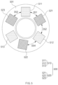
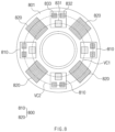
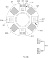
- FIGS. 9A and 9B are views illustrating arrangements of sensor modules of electronic devices according to embodiments
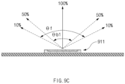
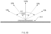
- FIGS. 9C and 9D are views for explaining beam angles of light emitting units illustrated in FIGS. 9A and 9B .
- each of the sensor modules 900 may include a plurality of light emitting units 910 and a plurality of light receiving units 920.
- the plurality of light emitting units 910 may include a first light emitting unit 911, a second light emitting unit 912, and a third light emitting unit 913.
- One of the first light emitting unit 911, the second light emitting unit 912, and the third light emitting unit 913 may have a beam angle different from that of at least one of the remaining light emitting units.
- the first light emitting unit 911 may have a wider beam angle than the second light emitting unit 912 and the third light emitting unit 913.
- the second light emitting unit 912 may have a narrower beam angle than the first light emitting unit 911 and the third light emitting unit 913.
- the third light emitting unit 913 may have a beam angle smaller than that of the first light emitting unit 911 and greater than that of the second light emitting unit 912.
- the plurality of light receiving units 920 may include a first light receiving unit 921, a second light receiving unit 922, and a third light receiving unit 923.
- the separation distances between the first to third light receiving units 921, 922, and 923 and the light emitting units 910 may be set depending on the beam angles of the adjacent light emitting units 910.
- the first light emitting unit 911 having a wider beam angle than the second light emitting unit 912 and the third light emitting unit 913 may be spaced apart from the first light receiving unit 921 and the third light receiving unit 923 by a first distance Da.
- the second light emitting unit 912 having a narrower beam angle than the first light emitting unit 911 and the third light emitting unit 913 may be spaced apart from the first light receiving unit 921 and the second light receiving unit 922 by a second distance Db shorter than the first distance Da.
- the third light emitting unit 913 having a beam angle narrower than that of the first light emitting unit 911 and wider than that of the second light emitting unit 912 may be spaced apart from the second light receiving unit 922 and the third light receiving unit 923 by a third distance Dc shorter than the first distance Da and longer than the second distance Db.
- the plurality of light emitting units 910 may include a first light emitting unit 911, a second light emitting unit 912, a third light emitting unit 913, and a fourth light emitting unit 914.
- the plurality of light receiving units 920 may include a first light receiving unit 921, a second light receiving unit 922, a third light receiving unit 923, and a fourth light receiving unit 924.
- the sensor module 900 illustrated in FIG. 9B may include substantially the same components as the sensor module illustrated in FIG. 9A , except that the sensor module 900 illustrated in FIG. 9B further includes the fourth light emitting unit 914 and the fourth light receiving unit 924. Accordingly, the previous descriptions may be applied to the same components or operations.
- Each of the first light emitting unit 911, the second light emitting unit 912, the third light emitting unit 913, and the fourth light emitting unit 914 illustrated in FIG. 9B may include a light that emits light in substantially the same wavelength band.
- each of the first light emitting unit 911, the second light emitting unit 912, the third light emitting unit 913, and the fourth light emitting unit 914 may include a first light body 931 that emits light in substantially the same wavelength band.
- Each of the first light emitting unit 911 and the third light emitting unit 913 may include a second light body 932 and a third light body 933 that emit light in different wavelength bands.
- the second light body 932 and the third light body 933 may emit light in the same wavelength band, or may emit light in different wavelength bands.
- the first light body 931 may output light in a green wavelength band that has a relatively high absorption coefficient.
- the absorption coefficient may refer to a coefficient indicating a rate at which output light emitted from the plurality of light emitting units 910 is reduced within a user's body.
- the light in the green wavelength band may be shallowly incident into the user's body tissue because the light in the green wavelength band has a relatively high absorption coefficient when compared to light in other wavelength bands. When the light in the green wavelength band is used, it is strong against motion, but the skin transmittance may be low.
- One of the second light body 932 and the third light body 933 may output light in a red wavelength band that has a relatively low absorption coefficient, and the other one of the second light body 932 and the third light body 933 may output light in an infrared wavelength band that has a relatively low absorption coefficient.
- the light in the red wavelength band or the light in the infrared wavelength band may be deeply incident into the user's body tissue because the light in the red wavelength band or the light in the infrared wavelength band has a relatively low absorption coefficient.
- the skin transmittance may be high.
- the signal strength may be weak, and the light may be sensitive to movement.
- light emitted from the plurality of light emitting units 910 may have various intensity ranges.
- the angle between the rays with light intensity of 10% of the maximum intensity may be referred to the as the field angle ⁇ f.
- the angle between the rays with 50% intensity may be referred to as the beam angle ⁇ b1 or ⁇ b2.
- an optical member formed of a lens structure 1020 may be disposed over the light emitting chip of the light 1010.
- the emissive region of light emitted from the light emitting chip at the first beam angle ⁇ b1 may be narrowed by the lens structure 1020, and therefore the first beam angle ⁇ b1 of the light 1010 may be reduced to the second beam angle ⁇ b2.
- the lens structure 1020 may include at least one of a total internal reflection (TIR) lens or a ball lens.
- TIR total internal reflection
- the light 1010 that does not include the lens structure 1020 may emit light at the first beam angle ⁇ b1.
- the light 1010 including the lens structure 1020 may emit light at the second beam angle ⁇ b2 smaller than the first beam angle ⁇ b1.
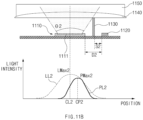
- the light 1110 may have the relatively wide first beam angle ⁇ 1.
- the light 1110 and the light receiving unit 1120 may be spaced apart from each other by a first distance D1.
- At least one of the light 1110 or the light receiving unit 1120 may be spaced apart from the partition wall 1130 by a first separation distance S1.
- the first output light beam LL1 emitted through the light 1110 having the first beam angle ⁇ 1 may be reflected from the body 1150 of the user.
- the reflected first output light beam LL1 may be obtained as the first reflected light beam PL1 with low light loss through the light receiving unit 1120 spaced apart from the light 1110 by the first distance D1.
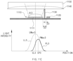
- the range of light applied to the user's skin may vary depending on the beam angle of the light 1110.
- the irradiation range of output light incident into the user's skin may be widened.
- the reflection range of reflected light obtained through the light receiving unit 1120 may also be widened, and thus a reflected light signal may be easy to measure.
- the first reflected light beam PL1 obtained through the light receiving unit 1120 disposed at the long separation distance from the light 1110 having the large beam angle may have a relatively wide light distribution range.
- the amplitude of the AC component of the first reflected light beam PL1 may be relatively small. Accordingly, it may be easy to remove motion artifacts included in the AC component of the first reflected light bam PL1, and an influence of the motion artifacts may be reduced.
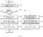
- FIG. 12 is a flowchart for explaining a method of identifying signal characteristics of a sensor module of an electronic device according to an embodiment.
- the processor 420 may identify reception of a request for obtaining a biometric signal corresponding to a body.
- the biometric signal corresponding to the body may be related to at least one of heart rate, stress index, blood oxygen saturation, maximum heart rate, body fat, local body fat, skin tone, melanin, wrinkle, skin moisture level, blood sugar, or blood pressure.
- the case based on the user's command may include a case in which the user executes an application related to the acquisition of the biometric signal.
- the case based on the user's command may include a case of receiving a user input for activating the sensor module 900 including the light 910 and the light receiving unit 920.
- the case based on the user's command may include a case of receiving a request for a user biometric signal from an external device through a communication module.
- the processor 420 may perform control such that at least one of the light receiving units 920 obtains light output through at least one of the light emitting units 910.
- the processor 420 may perform control such that the plurality of light receiving units 920 sequentially receive light signals as the plurality of light emitting units 910 are sequentially driven in operation 1202.
- the processor 420 may receive light signals sequentially detected through the first light receiving unit 921, the second light receiving unit 922, the third light receiving unit 923, and the fourth light receiving unit 924 after light beams sequentially emitted through the first light emitting unit 911, the second light emitting unit 912, the third light emitting unit 913, and the fourth light emitting unit 914 are reflected from the user's body.
- the processor 420 may perform control such that the plurality of light receiving units 920 simultaneously receive light signals as the plurality of light emitting units 910 are simultaneously driven in operation 1202.
- the processor 420 may receive light signals simultaneously detected through the first light receiving unit 921, the second light receiving unit 922, the third light receiving unit 923, and the fourth light receiving unit 924 after light beams simultaneously emitted through the first light emitting unit 911, the second light emitting unit 912, the third light emitting unit 913, and the fourth light emitting unit 914 are reflected from the user's body.
- the processor 420 may sense a biometric signal based on at least some of the sensed light signals.
- the processor 420 may sense a biometric signal by analyzing at least one of DC components or AC components of the light signals sensed through the first light receiving unit 921, the second light receiving unit 922, the third light receiving unit 923, and the fourth light receiving unit 924.
- the processor 420 may determine whether the electronic device is worn on the user's body, by analyzing the DC components of the light signals sensed through the plurality of light receiving units 920. When a DC component of a light signal sensed through at least one of the first light receiving unit 921, the second light receiving unit 922, the third light receiving unit 923, or the fourth light receiving unit 924 is greater than or equal to a specified value, the processor 420 may determine that the electronic device is worn on the user's body.
- the processor 420 may estimate a biometric signal including the user's oxygen saturation by analyzing the AC components and the DC components of the light signals sensed through the plurality of light receiving units 920.
- the processor 420 may estimate the oxygen saturation through the ratio between the magnitudes of the AC components and the magnitudes of the DC components of the light signals sensed through the plurality of light receiving units 920.
- the processor 420 may measure the user's oxygen saturation based on the ratio between the magnitudes of AC components and the magnitudes of DC components of red light signals sensed through the plurality of light receiving units 920 and the ratio between the magnitudes of AC components and the magnitudes of DC components of infrared light signals sensed through the plurality of light receiving units 920.
- the processor 420 may determine the user's biometric characteristics using at least one of a plurality of biometric signals.
- the processor 420 may compare characteristics of the plurality of biometric signals and may determine an optimal biometric signal for acquisition of biometric information based on the comparison result.
- the processor 420 may determine the user's biometric characteristics by analyzing a signal having a high frequency strength or AC component among the plurality of biometric signals as a main signal.
- the processor 420 may determine the user's biometric characteristics by analyzing the remaining signals other than the main signal among the plurality of biometric signals as auxiliary signals.
- the processor 420 may determine the user's biometric characteristics by averaging the auxiliary signals.
- the processor 420 may determine the user's biometric characteristics by analyzing a biometric signal sensed through the light receiving unit 920 having the shortest separation distance from the light emitting units 910 among the plurality of light receiving units 920 as the main signal.
- the processor 420 may determine the user's biometric characteristics by analyzing biometric signals sensed through the remaining light receiving units as auxiliary signals.
- the processor 420 may compare a plurality of biometric signals obtained through the plurality of light receiving units 920 and may select a biometric signal determined to be less affected by noise or may correct a signal based on identified noise.
- the noise may include at least one of motion artifacts or ambient noise.
- the processor 420 may obtain an accurate biometric signal by analyzing noise from one of the plurality of biometric signals and compensating for noise analyzed from another biometric signal among the plurality of biometric signals.
- the processor 420 may convert the sensed biometric signal into biometric information through a predetermined algorithm.
- the converted biometric information may be displayed through a user interface, or may be transferred to an external device.
- FIG. 13 is a flowchart for explaining a method of identifying signal characteristics of a sensor module of an electronic device according to an embodiment.
- operations may be sequentially performed. However, the operations are not necessarily sequentially performed. For example, the sequence of the operations may be changed, or at least two operations may be performed in parallel.
- Operations of the electronic device including the sensor module according to the embodiment illustrated in FIG. 13 (e.g., the sensor module 176 of FIG. 1 , the sensor module 410 of FIG. 4 , the sensor module 500 of FIG. 5 , the sensor module 600 of FIG. 6 , the sensor module 700 of FIGS. 7A and 7B , the sensor module 800 of FIG. 8 , or the sensor module 900 of FIGS. 9A and 9B ) may be performed by a processor (e.g., the processor 120 of FIG. 1 or the processor 420 of FIG. 4 ).
- a processor e.g., the processor 120 of FIG. 1 or the processor 420 of FIG. 4 .
- the following description will be given with reference to the biometric signal processing device 401 (or, the electronic device) of FIG. 4 and the structure of the sensor module 900 of FIG. 9B . Meanwhile, description of the technical features described above will hereinafter be omitted.
- the processor 420 may identify reception of a request for obtaining a biometric signal corresponding to a body. For example, the processor 420 may perform an operation substantially the same as operation 1201 of FIG. 12 .
- the processor 420 may sense movement of the electronic device 401 and may determine a current state of a user wearing the electronic device 401 (e.g., a normal state, a sleep state, an exercise state, or a state in which a specified event occurs), based on the degree of the sensed movement. For example, the processor 420 may determine the current state of the user wearing the electronic device 401, based on a motion signal of a motion sensor included in the sensor module. The motion sensor may be electrically connected with the processor 420 and may provide a motion signal generated depending on the detection of movement of the electronic device 401 to the processor 420.
- a current state of a user wearing the electronic device 401 e.g., a normal state, a sleep state, an exercise state, or a state in which a specified event occurs
- the motion sensor may be electrically connected with the processor 420 and may provide a motion signal generated depending on the detection of movement of the electronic device 401 to the processor 420.
- the processor 420 may, in operation 1303, drive at least one of the plurality of light emitting units 910 included in the sensor module 900. For example, in operation 1303, the processor 420 may perform an operation substantially the same as operation 1202.
- the processor 420 may sense a biometric signal based at least partly on the sensed light signal. For example, in operation 1305, the processor 420 may perform an operation substantially the same as operation 1204.
- the processor 420 may, in operation 1306, perform control to drive a light 910 selected from the plurality of light emitting units 910 included in the sensor module 900. For example, the processor 420 may perform control to drive (e.g., activate or turn on) a light 910 having a relatively small beam angle among the plurality of light emitting units 910. The processor 420 may perform control so as not to drive a light 910 having a relatively large beam angle among the plurality of light emitting units 910.
- the processor 420 may perform control such that among the first to fourth light emitting units 911, 912, 913, and 914, the second light emitting unit 912 having a relatively small beam angle is driven and the first light emitting unit 911, the third light emitting unit 913, and the fourth light emitting unit 914 that have relatively large beam angles are not driven.
- the processor 420 may perform control such that the plurality of light emitting units 910 output light having a specified range of output intensity.
- the processor 420 may perform control such that the second light 912 having a relatively small beam angle outputs light having low intensity when compared to the first light emitting unit 911, the third light emitting unit 913, and the fourth light emitting unit 914 that have relatively large beam angles.
- the processor 420 may perform control such that the second light emitting unit 912 having a relatively small beam angle outputs light having lower intensity when the user makes a little movement than when the user makes a big movement.
- the processor 420 may perform control to drive a light receiving unit 920 selected from the plurality of light receiving units. For example, the processor 420 may perform control to drive a light receiving unit 920 disposed at a short distance from a light 910 having a relatively small beam angle among the plurality of light receiving units 920. The processor 420 may perform control so as not to drive a light receiving unit 920 disposed at a long distance from a light 910 having a relatively large beam angle among the plurality of light receiving units 920. For example, the processor 420 may perform control to drive the second light receiving unit 922 disposed at a short distance from the second light 912 having a relatively small beam angle among the first to fourth light receiving units 921, 922, 923, and 924.
- the processor 420 may perform control such that among the plurality of light receiving units, a light receiving unit 920 disposed at a short distance from the light emitting units 910 obtains light output through a light 910 having a relatively small beam angle.
- the processor 420 may convert the sensed biometric signal into biometric information through a predetermined algorithm.
- the converted biometric information may be displayed through a user interface, or may be transferred to an external device.
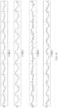
- FIG. 14 illustrates biometric signals obtained through an electronic device according to an embodiment.
- the electronic device may obtain a plurality of biometric signals through an optical sensor including a plurality of light emitting units and a plurality of light receiving units.
- a first biometric signal 1401 may be a biometric signal obtained by driving a first light emitting unit (e.g., the first light 911 emitting unit of FIG. 9B ) and removing noise from a light signal received through a first light receiving unit (e.g., the first light receiving unit 921 of FIG. 9B ).
- a second biometric signal 1402 may be a biometric signal obtained by driving a second light emitting unit (e.g., the second light emitting unit 912 of FIG.
- the accuracy and quality of a biometric signal may be degraded depending on a body structure of a user wearing an electronic device and a current state of the user.
- the processor may obtain light signals emitted from the first light emitting unit, the second light emitting unit, and the third light emitting unit through the first light receiving unit, the second light receiving unit, and the third light receiving unit when the object to be measured, on which the electronic device is worn, makes a movement exceeding a predetermined distance and may obtain a light signal emitted from the second light emitting unit through the first light receiving unit and the second light receiving unit when the object to be measured makes a movement less than the predetermined distance.
- the processor may perform control to turn on the first light emitting unit, the second light emitting unit, the third light emitting unit, the first light receiving unit, the second light receiving unit, and the third light receiving unit when the object to be measured, on which the electronic device is worn, makes a movement exceeding a predetermined distance and may perform control to turn off the first light emitting unit, the third light emitting unit, and the third light receiving unit and turn on at least one of the second light emitting unit, the first light receiving unit, or the second light receiving unit when the object to be measured makes a movement less then the predetermined distance.
- the processor may perform control such that at least one of the first light emitting unit, the second light emitting unit, or the third light emitting unit emits light having a specified first intensity when the object to be measured, on which the electronic device is worn, makes a movement exceeding a predetermined distance and may perform control such that the second light emitting unit emits light having a second intensity lower than the first intensity when the object to be measured, on which the electronic device is worn, makes a movement less than the predetermined distance.
- an electronic device may include a plurality of light emitting units spaced apart from each other to form a ring shape, at least one light receiving unit disposed between the plurality of light emitting units, and a processor that analyzes light generated from the light emitting units and incident to the light receiving unit.
- Each of a first one or more light emitting units and a second one or more light emitting units included in the plurality of light emitting units may include at least one first light body that emits light in a specified wavelength band.
- the first body of the first one or more light emitting units and the first light body of the second one or more light emitting units may have different beam angles.
- a separation distance between the first light body of the first one or more light emitting units and the light receiving unit may be different from a separation distance between the first light body of the second one or more light emitting units and the light receiving unit.
- the plurality of light emitting units may include the first one or more light emitting units, the second one or more light emitting units having a smaller beam angle than the first one or more light emitting units, and a third one or more light emitting units having a beam angle smaller than a beam angle of the first one or more light emitting units and greater than a beam angle of the second one or more light emitting units.
- the at least one light receiving unit may include a first light receiving unit, a second light receiving unit, and a third light receiving unit.
- the first one or more light emitting units may be disposed between the first light receiving unit and the third light receiving unit and may be spaced apart from the first light receiving unit and the third light receiving unit by a first distance.
- the second one or more light emitting units may be disposed between the first light receiving unit and the second light receiving unit and may be spaced apart from the first light receiving unit and the second light receiving unit by a second distance different from the first distance.
- the third one or more light emitting units may be disposed between the second light receiving unit and the third light receiving unit and may be spaced apart from the second light receiving unit and the third light receiving unit by a third distance smaller than the first distance and greater than the second distance.
- the processor may identify a current state of an object to be measured on which the electronic device is worn, may obtain light signals emitted from the first one or more light emitting units, the second one or more light emitting units, and the third one or more light emitting units through the first light receiving unit, the second light receiving unit, and the third light receiving unit when the object to be measured, on which the electronic device is worn, makes a big movement, and may obtain a light signal emitted from one of the first light emitting units, the second one or more light emitting units, and the third one or more light emitting units through at least two of the first light receiving unit, the second light receiving unit, and the third light receiving unit when the object to be measured makes a little movement.
- the distances between the light emitting units and the light receiving units may be set to be suitable for the user's body structure, and thus the quality of a biometric signal may be improved.
- the driving of the light emitting units may be controlled depending on the user's current state, and thus the quality of a biometric signal may be improved.
- signal quality performance may be maintained by controlling the driving of the light emitting units depending on the user's current state.
- the electronic device may be one of various types of electronic devices.
- the electronic devices may include, for example, a portable communication device (e.g., a smartphone), a computer device, a portable multimedia device, a portable medical device, a camera, a wearable device, or a home appliance. According to an embodiment of the disclosure, the electronic devices are not limited to those described above.
- each of such phrases as “A or B,” “at least one of A and B,” “at least one of A or B,” “A, B, or C,” “at least one of A, B, and C,” and “at least one of A, B, or C,” may include any one of, or all possible combinations of the items enumerated together in a corresponding one of the phrases.
- such terms as “1 st “ and “2 nd ,” or “first” and “second” may be used to simply distinguish a corresponding component from another, and does not limit the components in other aspect (e.g., importance or order).
- an element e.g., a first element
- the element may be coupled with the other element directly (e.g., wiredly), wirelessly, or via a third element.
- each component e.g., a module or a program of the above-described components may include a single entity or multiple entities and some of multiple entities may be separately disposed on the other components.
- one or more of the above-described components may be omitted, or one or more other components may be added.
- a plurality of components e.g., modules or programs
- the integrated component may still perform one or more functions of each of the plurality of components in the same or similar manner as they are performed by a corresponding one of the plurality of components before the integration.
- operations performed by the module, the program, or another component may be carried out sequentially, in parallel, repeatedly, or heuristically, or one or more of the operations may be executed in a different order or omitted, or one or more other operations may be added.
Landscapes
- Health & Medical Sciences (AREA)
- Life Sciences & Earth Sciences (AREA)
- Physics & Mathematics (AREA)
- Engineering & Computer Science (AREA)
- Public Health (AREA)
- Surgery (AREA)
- Veterinary Medicine (AREA)
- General Health & Medical Sciences (AREA)
- Animal Behavior & Ethology (AREA)
- Biophysics (AREA)
- Pathology (AREA)
- Biomedical Technology (AREA)
- Heart & Thoracic Surgery (AREA)
- Medical Informatics (AREA)
- Molecular Biology (AREA)
- Cardiology (AREA)
- Physiology (AREA)
- Spectroscopy & Molecular Physics (AREA)
- Optics & Photonics (AREA)
- Signal Processing (AREA)
- Artificial Intelligence (AREA)
- Computer Vision & Pattern Recognition (AREA)
- Psychiatry (AREA)
- Measurement Of The Respiration, Hearing Ability, Form, And Blood Characteristics Of Living Organisms (AREA)
- Telephone Function (AREA)
Applications Claiming Priority (3)
| Application Number | Priority Date | Filing Date | Title |
|---|---|---|---|
| KR20220158480 | 2022-11-23 | ||
| KR1020220179233A KR20240076335A (ko) | 2022-11-23 | 2022-12-20 | 센서 모듈을 포함하는 전자 장치 |
| PCT/KR2023/017025 WO2024111919A1 (ko) | 2022-11-23 | 2023-10-30 | 센서 모듈을 포함하는 전자 장치 |
Publications (2)
| Publication Number | Publication Date |
|---|---|
| EP4582018A1 true EP4582018A1 (de) | 2025-07-09 |
| EP4582018A4 EP4582018A4 (de) | 2025-10-08 |
Family
ID=91080872
Family Applications (1)
| Application Number | Title | Priority Date | Filing Date |
|---|---|---|---|
| EP23894848.3A Pending EP4582018A4 (de) | 2022-11-23 | 2023-10-30 | Elektronische vorrichtung mit sensormodul |
Country Status (3)
| Country | Link |
|---|---|
| US (1) | US20240164715A1 (de) |
| EP (1) | EP4582018A4 (de) |
| CN (1) | CN120265203A (de) |
Family Cites Families (12)
| Publication number | Priority date | Publication date | Assignee | Title |
|---|---|---|---|---|
| JP5056867B2 (ja) * | 2009-07-01 | 2012-10-24 | カシオ計算機株式会社 | 生体情報検出装置および生体情報検出方法 |
| US11478158B2 (en) * | 2013-05-23 | 2022-10-25 | Medibotics Llc | Wearable ring of optical biometric sensors |
| US20150018647A1 (en) * | 2013-07-09 | 2015-01-15 | Xerox Corporation | Method and apparatus for monitoring a subject for blood oxygen saturation |
| KR102138510B1 (ko) * | 2013-08-27 | 2020-07-28 | 엘지전자 주식회사 | 근접 터치 기능을 구비한 전자 장치 및 그 제어 방법 |
| US10849514B2 (en) * | 2015-06-02 | 2020-12-01 | Sony Corporation | Information processing device and information processing method |
| US11224782B2 (en) * | 2017-06-04 | 2022-01-18 | Apple Inc. | Physical activity monitoring and motivating with an electronic device |
| KR102408028B1 (ko) * | 2017-09-06 | 2022-06-13 | 삼성전자 주식회사 | 착용 상태에 기반한 생체 정보 획득 방법 및 그 전자 장치 |
| KR102396867B1 (ko) * | 2017-09-26 | 2022-05-12 | 애플 인크. | 광학적 감지를 위한 동심 아키텍처 |
| KR102747656B1 (ko) * | 2019-02-18 | 2024-12-31 | 삼성전자주식회사 | 생체 센서를 포함하는 웨어러블 전자 장치 |
| US11717197B2 (en) * | 2019-09-27 | 2023-08-08 | Apple Inc. | Physiological monitoring system for measuring oxygen saturation |
| KR20220099404A (ko) * | 2021-01-06 | 2022-07-13 | 삼성전자주식회사 | 복수의 광학 센서를 구비한 전자 장치 및 그 제어 방법 |
| KR20220138631A (ko) * | 2021-04-06 | 2022-10-13 | 삼성전자주식회사 | 웨어러블 전자 장치 |
-
2023
- 2023-10-30 CN CN202380081301.9A patent/CN120265203A/zh active Pending
- 2023-10-30 EP EP23894848.3A patent/EP4582018A4/de active Pending
- 2023-11-01 US US18/386,016 patent/US20240164715A1/en active Pending
Also Published As
| Publication number | Publication date |
|---|---|
| US20240164715A1 (en) | 2024-05-23 |
| EP4582018A4 (de) | 2025-10-08 |
| CN120265203A (zh) | 2025-07-04 |
Similar Documents
| Publication | Publication Date | Title |
|---|---|---|
| US11903733B2 (en) | Electronic device for measuring bio-signals | |
| US12383152B2 (en) | Electronic device including multiple optical sensors and method for controlling the same | |
| KR20220099404A (ko) | 복수의 광학 센서를 구비한 전자 장치 및 그 제어 방법 | |
| US11963292B2 (en) | Patterned cover member and electronic device including same | |
| EP4302683A1 (de) | Tragbare elektronische vorrichtung | |
| KR20240076335A (ko) | 센서 모듈을 포함하는 전자 장치 | |
| US12588871B2 (en) | Method for calibrating external light for bio-signal measurement, and electronic device and storage medium therefor | |
| US20260114745A1 (en) | Electronic device comprising optical sensor and bio-impedance detection sensor | |
| US20240415457A1 (en) | Wearable electronic device including plurality of biometric sensors | |
| EP4582018A1 (de) | Elektronische vorrichtung mit sensormodul | |
| US12569200B2 (en) | Electronic device for providing biometric information and operating method thereof | |
| US12188824B2 (en) | Method and electronic device for detecting wearing using polarization | |
| US20230032169A1 (en) | Sensor structure and electronic device including same | |
| KR20220155029A (ko) | 편광을 이용하여 착용을 감지하는 전자 장치 및 방법 | |
| KR20240021078A (ko) | 산소 포화도를 측정하는 전자 장치 및 이의 제어 방법 | |
| KR20230077932A (ko) | 생체 정보를 제공하는 전자 장치 및 그 동작 방법 | |
| EP4394525A1 (de) | Elektronische vorrichtung mit struktur zur erleichterung des betriebs mehrerer sensoren mit verschiedenen optischen eigenschaften | |
| US20250281083A1 (en) | Oxygen saturation measurement guide method and wearable device therefor | |
| US20250072830A1 (en) | Electronic device including light-emitting structure | |
| CN116113357B (zh) | 执行使用生物特征信号的功能的方法和支持其的电子设备 | |
| US20240008775A1 (en) | Electronic device and method for obtaining biometric information | |
| KR20240028894A (ko) | 생체 정보를 측정하는 전자 장치 및 이의 동작 방법 | |
| US20220192530A1 (en) | Electronic device including sensor array and method for controlling thereof | |
| KR20240007569A (ko) | 생체 정보를 획득하기 위한 전자 장치 및 방법 | |
| WO2024111919A1 (ko) | 센서 모듈을 포함하는 전자 장치 |
Legal Events
| Date | Code | Title | Description |
|---|---|---|---|
| STAA | Information on the status of an ep patent application or granted ep patent |
Free format text: STATUS: THE INTERNATIONAL PUBLICATION HAS BEEN MADE |
|
| PUAI | Public reference made under article 153(3) epc to a published international application that has entered the european phase |
Free format text: ORIGINAL CODE: 0009012 |
|
| STAA | Information on the status of an ep patent application or granted ep patent |
Free format text: STATUS: REQUEST FOR EXAMINATION WAS MADE |
|
| 17P | Request for examination filed |
Effective date: 20250402 |
|
| AK | Designated contracting states |
Kind code of ref document: A1 Designated state(s): AL AT BE BG CH CY CZ DE DK EE ES FI FR GB GR HR HU IE IS IT LI LT LU LV MC ME MK MT NL NO PL PT RO RS SE SI SK SM TR |
|
| A4 | Supplementary search report drawn up and despatched |
Effective date: 20250909 |
|
| RIC1 | Information provided on ipc code assigned before grant |
Ipc: A61B 5/024 20060101AFI20250903BHEP Ipc: A61B 5/00 20060101ALI20250903BHEP |
|
| DAV | Request for validation of the european patent (deleted) | ||
| DAX | Request for extension of the european patent (deleted) |