EP4581983A1 - Slide rail mechanism - Google Patents
Slide rail mechanism Download PDFInfo
- Publication number
- EP4581983A1 EP4581983A1 EP24200753.2A EP24200753A EP4581983A1 EP 4581983 A1 EP4581983 A1 EP 4581983A1 EP 24200753 A EP24200753 A EP 24200753A EP 4581983 A1 EP4581983 A1 EP 4581983A1
- Authority
- EP
- European Patent Office
- Prior art keywords
- rail
- carried object
- locking member
- slide rail
- predetermined
- Prior art date
- Legal status (The legal status is an assumption and is not a legal conclusion. Google has not performed a legal analysis and makes no representation as to the accuracy of the status listed.)
- Granted
Links
Images




Classifications
-
- A—HUMAN NECESSITIES
- A47—FURNITURE; DOMESTIC ARTICLES OR APPLIANCES; COFFEE MILLS; SPICE MILLS; SUCTION CLEANERS IN GENERAL
- A47B—TABLES; DESKS; OFFICE FURNITURE; CABINETS; DRAWERS; GENERAL DETAILS OF FURNITURE
- A47B88/00—Drawers for tables, cabinets or like furniture; Guides for drawers
- A47B88/50—Safety devices or the like for drawers
- A47B88/57—Safety devices or the like for drawers preventing complete withdrawal of the drawer
-
- A—HUMAN NECESSITIES
- A47—FURNITURE; DOMESTIC ARTICLES OR APPLIANCES; COFFEE MILLS; SPICE MILLS; SUCTION CLEANERS IN GENERAL
- A47B—TABLES; DESKS; OFFICE FURNITURE; CABINETS; DRAWERS; GENERAL DETAILS OF FURNITURE
- A47B88/00—Drawers for tables, cabinets or like furniture; Guides for drawers
- A47B88/50—Safety devices or the like for drawers
-
- A—HUMAN NECESSITIES
- A47—FURNITURE; DOMESTIC ARTICLES OR APPLIANCES; COFFEE MILLS; SPICE MILLS; SUCTION CLEANERS IN GENERAL
- A47B—TABLES; DESKS; OFFICE FURNITURE; CABINETS; DRAWERS; GENERAL DETAILS OF FURNITURE
- A47B88/00—Drawers for tables, cabinets or like furniture; Guides for drawers
- A47B88/70—Coupled drawers
- A47B88/75—Coupled drawers the secondary drawer being in or above the primary drawer
-
- E—FIXED CONSTRUCTIONS
- E05—LOCKS; KEYS; WINDOW OR DOOR FITTINGS; SAFES
- E05B—LOCKS; ACCESSORIES THEREFOR; HANDCUFFS
- E05B65/00—Locks or fastenings for special use
- E05B65/46—Locks or fastenings for special use for drawers
- E05B65/462—Locks or fastenings for special use for drawers for two or more drawers
- E05B65/463—Drawer interlock or anti-tilt mechanisms, i.e. when one drawer is open, at least one of the remaining drawers is locked
-
- A—HUMAN NECESSITIES
- A47—FURNITURE; DOMESTIC ARTICLES OR APPLIANCES; COFFEE MILLS; SPICE MILLS; SUCTION CLEANERS IN GENERAL
- A47B—TABLES; DESKS; OFFICE FURNITURE; CABINETS; DRAWERS; GENERAL DETAILS OF FURNITURE
- A47B2210/00—General construction of drawers, guides and guide devices
- A47B2210/0002—Guide construction for drawers
- A47B2210/0064—Guide sequencing or synchronisation
-
- A—HUMAN NECESSITIES
- A47—FURNITURE; DOMESTIC ARTICLES OR APPLIANCES; COFFEE MILLS; SPICE MILLS; SUCTION CLEANERS IN GENERAL
- A47B—TABLES; DESKS; OFFICE FURNITURE; CABINETS; DRAWERS; GENERAL DETAILS OF FURNITURE
- A47B2210/00—General construction of drawers, guides and guide devices
- A47B2210/07—Drawers with sliding trays
-
- A—HUMAN NECESSITIES
- A47—FURNITURE; DOMESTIC ARTICLES OR APPLIANCES; COFFEE MILLS; SPICE MILLS; SUCTION CLEANERS IN GENERAL
- A47B—TABLES; DESKS; OFFICE FURNITURE; CABINETS; DRAWERS; GENERAL DETAILS OF FURNITURE
- A47B88/00—Drawers for tables, cabinets or like furniture; Guides for drawers
- A47B88/40—Sliding drawers; Slides or guides therefor
- A47B88/49—Sliding drawers; Slides or guides therefor with double extensible guides or parts
Definitions
- the present invention is related to a slide rail mechanism.
- US patent number US 4,925,257 discloses a piece of furniture having a cabinet with two drawers. Each drawer is slidable relative to the cabinet between an open position and a closed position.
- the piece of furniture comprises a lock bar mounted to the cabinet and configured to be moved between a first position and a second position.
- the lock bar is configured to interact with a cooperating means mounted to the drawer for preventing the two drawers from being simultaneously moved from the closed position to the open position.
- US patent number US 6,722,749 B1 discloses a drawer open position controller comprising a ramp, a blocking device and a locking member arranged on the cabinet.
- a follower drives the locking member to move, such that other drawers are blocked through the ramp and the blocking device, and can only be pulled out a certain distance .
- the aforementioned patents respectively disclose a piece of furniture capable of preventing two drawers from being simultaneously opened, and a drawer open position controller capable of preventing, when a first drawer has been opened, other drawers from being fully opened.
- a drawer open position controller capable of preventing, when a first drawer has been opened, other drawers from being fully opened.
- the present invention aims at providing a slide rail mechanism.
- the slide rail mechanism comprises a first carried object, a first slide rail assembly, a second slide rail assembly and a locking member.
- the first slide rail assembly comprises a first rail and a second rail longitudinally movable relative to the first rail.
- the first rail is configured to be mounted to the rack, and the second rail is configured to carry the first carried object.
- the second slide rail assembly is arranged on the first carried object.
- the second slide rail assembly comprises a third rail and a fourth rail longitudinally movable relative to the third rail.
- the third rail is configured to be mounted to the first carried object, and the fourth rail is configured to carry a second carried object.
- the locking member is movably mounted to the first carried object.
- the first rail is arranged with an auxiliary feature, and the locking member is arranged with a predetermined part and a locking part.
- the auxiliary feature is configured to support the predetermined part to position the locking member at a first predetermined position, such that the locking part of the locking member is not configured to prevent the fourth rail from being moved along an opening direction, in order to allow the second carried object to be moved relative to the first carried object along the opening direction.
- the locking member is moved from the first predetermined position to a second predetermined position, such that the locking part of the locking member is configured to prevent the fourth rail from being moved along the opening direction, in order to limit a moving distance of the second carried object relative to the first carried object along the opening direction.
- a slide rail mechanism is applicable to a rack 22 according to an embodiment of the present invention.
- the slide rail mechanism comprises a first slide rail assembly 24, a second slide rail assembly 26 and a first carried object 28.
- the first slide rail assembly 24 is configured to support the first carried object 28.
- the first carried object 28 can be an outer casing.
- the second slide rail assembly 26 is arranged on the first carried object 28.
- the second slide rail assembly 26 is arranged at an inner side of the first carried object 28 (the outer casing), and the second slide rail assembly 26 is configured to support a second carried object 30.
- the first carried object 28 is formed with a predetermined space 32 for accommodating the second carried object 30.
- the slide rail mechanism further comprises a locking member 34 movably mounted on the first carried object 28.
- the first slide rail assembly 24 comprises a first rail 36 and a second rail 38 longitudinally movable relative to the first rail 36.
- the first slide rail assembly 24 further comprises a first middle rail 40 movably mounted between the first rail 36 and the second rail 38.
- the X axis is a longitudinal direction (or a length direction or moving direction of the slide rail)
- the Y axis is a transverse direction (or a lateral direction of the slide rail)
- the Z axis is a vertical direction (or a height direction of the slide rail) .
- the first rail 36 is configured to be mounted to the rack 22, and the second rail 38 is configured to carry the first carried object 28.
- the locking member 34 can be a linkage rod, and a moving direction of the locking member 34 is a height direction of the first carried object 28 (such as the Z-axis direction).
- the first rail 36 is arranged with a first auxiliary feature 42.
- the first rail 36 is further arranged with a second auxiliary feature 44 (as shown in FIG. 3 ).
- the first slide rail assembly 24 further comprises a bracket 46.
- the first rail 36 is mounted to the rack 22 through the bracket 46.
- the bracket 46 is connected (such as fixedly connected) to the first rail 36 and can be seen as a portion of the first rail 36.
- the first auxiliary feature 42 and the second auxiliary feature 44 are arranged on the bracket 46 on the first rail 36.
- the bracket 46 has a first end part 46a and a second end part 46b opposite to each other, such as a front end part and a rear end part.
- the first auxiliary feature 42 and the second auxiliary feature 44 are arranged adjacent to the first end part 46a of the bracket 46, but the present invention is not limited thereto.
- first auxiliary feature 42 and the second auxiliary feature 44 are protrusions, and the first auxiliary feature 42 and the second auxiliary feature 44 are spaced apart from each other by a longitudinal distance along the longitudinal direction.
- the first auxiliary feature 42 and the second auxiliary feature 44 respectively have a first guiding section G1 and a second guiding section G2 corresponding to each other.
- Each of the first guiding section G1 and the second guiding section G2 has an inclined surface or an arc surface, but the present invention is not limited thereto.
- the first carried object 28 comprises a plurality of walls.
- the first carried object 28 comprises a predetermined wall 48 (or a side wall).
- the predetermined wall 48 has a first side L1 and a second side L2 opposite to each other, such as an outer side and an inner side, but the present invention is not limited thereto.
- the first side L1 of the predetermined wall 48 is connected to the second rail 38, and the predetermined space 32 is formed adjacent to the second side L2.
- the locking member 34 is arranged with a predetermined part 50 and a locking part 52.
- the locking member 34 is movably mounted to the second side L2 of the predetermined wall 48 of the first carried object 28.
- An extension section 50a of the predetermined part 50 of the locking member 34 is configured to penetrate through the predetermined wall 48 to extend to the first side L1 (as shown in FIG. 2 ).
- the predetermined wall 48 is formed with a limiting structure 54, such as an oval hole (as shown in FIG. 2 ), but the present invention is not limited thereto.
- the extension section 50a of the predetermined part 50 is inserted into the limiting structure 54 of the predetermined wall 48, such that the locking member 34 is movable relative to the first carried object 28 within a limited range.
- the second slide rail assembly 26 comprises a third rail 56 and a fourth rail 58 longitudinally movable relative to the third rail 56.
- the third rail 56 is configured to be mounted to the second side L2 of the predetermined wall 48 of the first carried object 28, and the fourth rail 58 is configured to carry the second carried object 30.
- the third rail 56 has a first side L1' and a second side L2' opposite to each other, such as an outer side and an inner side, but the present invention is not limited thereto.
- the first side L1' of the third rail 56 is connected to the second side L2 of the first carried object 28, and the second side L2' of the third rail 56 is adjacent to the fourth rail 58.
- the third rail 56 is formed with an auxiliary space 60 (such as a through hole) communicating the first side L1' and the second side L2' of the third rail 56.
- the auxiliary space 60 is configured to allow the locking part 52 of the locking member 34 to pass through the third rail 56 from the first side L1' of the third rail 56 to the second side L2' of the third rail 56.
- the second slide rail assembly 26 further comprises a second middle rail 62 movably mounted between the third rail 56 and the fourth rail 58, and the second middle rail 62 has a blocking feature 64 configured to interact with the locking part 52 of the locking member 34.
- the blocking feature 64 is a protrusion, but the present invention is not limited thereto.
- the first carried object 28 is mounted with a plurality of second slide rail assemblies 26.
- the second slide rail assemblies 26 have substantially identical structural configuration.
- the fourth rail 58 of each of the second slide rail assemblies 26 is configured to carry the respective second carried object 30.
- the locking part 52 of the locking member 34 passes through the auxiliary space 60 of the third rail 56 to be adjacent to the fourth rail 58 (and the second middle rail 62).
- the first auxiliary feature 42 is configured to support the predetermined part 50 (the extension section 50a of the predetermined part 50), such that the locking member 34 is positioned at a first predetermined position K1.
- the locking part 52 of the locking member 34 is not aligned with the blocking feature 64 of the second middle rail 62 along the longitudinal direction.
- a vertical position of the locking part 52 of the locking member 34 along the vertical direction does not correspond to a vertical position of the blocking feature 64 of the second middle rail 62 along the vertical direction (a transverse position of the locking part 52 of the locking member 34 along the transverse direction corresponds to a transverse position of the blocking feature 64 of the second middle rail 62 along the transverse direction).
- the locking part 52 of the locking member 34 and the blocking feature 64 of the second middle rail 62 are spaced apart from each other by a predetermined longitudinal distance M along the longitudinal direction (as shown in FIG. 5 ).
- the first auxiliary feature 42 no longer supports the predetermined part 50, such that the locking member 34 is moved from the first predetermined position K1 along a predetermined height direction H (as shown in FIG. 5 ) to a second predetermined position K2 (as shown in FIG. 7 and FIG. 8 ) .
- the locking part 52 of the locking member 34 is configured to prevent the fourth rail 58 from being moved along the opening direction D1 in order to limit a moving distance of the second carried object 30 relative to the first carried object 28 along the opening direction D1.
- the locking part 52 of the locking member 34 is configured to block a moving path of the blocking feature 64 of the second middle rail 62 along the opening direction D1, in order to prevent the fourth rail 58 from being moved along the opening direction D1.
- the locking member 34 is located at the second predetermined position K2
- the locking part 52 of the locking member 34 is aligned with the blocking feature 64 of the second middle rail 62 along the longitudinal direction.
- the second middle rail 62 is configured to indirectly prevent the fourth rail 58 from being moved along the opening direction D1 (for example, a synchronization mechanism is provided between the second middle rail 62 and the fourth rail 58), in order to limit the moving distance of the second carried object 30 relative to the first carried object 28 along the opening direction D1.
- the second slide rail assembly 26 only comprises the third rail 56 and the fourth rail 58 (that is, the second slide rail assembly 26 does not comprise the second middle rail 62), and the fourth rail 58 is configured to carry the second carried object 30 and has a blocking feature.
- the locking part 52 of the locking member 34 is aligned with the blocking feature of the fourth rail 58 along the longitudinal direction (a vertical position of the locking part 52 of the locking member 34 along the vertical direction corresponds to a vertical position of the blocking feature of the fourth rail 58 along the vertical direction, and a transverse position of the locking part 52 of the locking member 34 along the transverse direction corresponds to a transverse position of the blocking feature of the fourth rail 58 along the transverse direction), such that the locking member 34 is configured to directly block a moving path of the fourth rail 58 along the opening direction D1, in order to limit the moving distance of the second carried object 30 relative to the first carried object 28 along the opening direction D1.
- the second guiding section G2 of the second auxiliary feature 44 is configured to contact and guide the predetermined part 50 (the extension section 50a of the predetermined part 50) of the locking member 34 to move the locking member 34 from the first predetermined position K1 (as shown in the FIG. 5 ) to the second predetermined position K2 (as shown in FIG. 7 and FIG. 8 ) .
- the locking member 34 can also be moved down to the second predetermined position K2 due to gravity.
- the locking part 52 of the locking member 34 and the blocking feature 64 of the second middle rail 62 are aligned with each other along the longitudinal direction to block each other (as shown in FIG. 10 and FIG. 11 ), so as to indirectly prevent the fourth rail 58 from being moved along the opening direction D1, in order to limit the moving distance of the second carried object 30 relative to the first carried object 28 along the opening direction D1.
- the second carried object 30 is movable relative to the first carried object 28 from a predetermined retracted position R' (as shown in FIG. 9 ) along the opening direction D1, and only can be pulled out relative to the first carried object 28 by a predetermined extension distance Q (as shown in FIG. 10 ).
- the second carried object 30 is configured to be prevented from being moved relative to the first carried object 28 from the predetermined retracted position R' along the opening direction D1. In other words, the second carried object 30 cannot be fully opened relative to the first carried object 28.
- the first guiding section G1 of the first auxiliary feature 42 is configured to contact and guide the predetermined part 50 (the extension section 50a of the predetermined part 50) of the locking member 34 to move the locking member 34 from the second predetermined position K2 (as shown in the FIG. 9 and FIG. 10 ) to the first predetermined position K1 (as shown in FIG. 5 and FIG. 6 ).
- the first auxiliary feature 42 is configured to support the predetermined part 50 to position the locking member 34 at the first predetermined position K1, such that the locking part 52 of the locking member 34 is not aligned with the blocking feature 64 of the second middle rail 62 along the longitudinal direction. Therefore, the locking part 52 of the locking member 34 is not configured to prevent the fourth rail 58 from being moved along the opening direction D1, in order to allow the second carried object 30 to be moved relative to the first carried object 28 from the predetermined retracted position R' (as shown in FIG. 9 ) along the opening direction D1 to a predetermined extended position, such as a fully extended position E' (as shown in FIG. 12 ).
- the slide rail mechanism according to the embodiments of the present invention has the following technical features:
Landscapes
- Drawers Of Furniture (AREA)
- Automatic Analysis And Handling Materials Therefor (AREA)
- Warehouses Or Storage Devices (AREA)
Abstract
Description
- The present invention is related to a slide rail mechanism.
- US patent number
US 4,925,257 discloses a piece of furniture having a cabinet with two drawers. Each drawer is slidable relative to the cabinet between an open position and a closed position. The piece of furniture comprises a lock bar mounted to the cabinet and configured to be moved between a first position and a second position. The lock bar is configured to interact with a cooperating means mounted to the drawer for preventing the two drawers from being simultaneously moved from the closed position to the open position. - US patent number
US 6,722,749 B1 discloses a drawer open position controller comprising a ramp, a blocking device and a locking member arranged on the cabinet. When the bottom drawer is pulled out of the cabinet, a follower drives the locking member to move, such that other drawers are blocked through the ramp and the blocking device, and can only be pulled out a certain distance . - The aforementioned patents respectively disclose a piece of furniture capable of preventing two drawers from being simultaneously opened, and a drawer open position controller capable of preventing, when a first drawer has been opened, other drawers from being fully opened. However, for different market requirements, it is important to develop various products.
- This in mind, the present invention aims at providing a slide rail mechanism.
- This is achieved by a slide rail mechanism according to
claim 1. The dependent claims pertain to corresponding further developments and improvements. - As will be seen more clearly from the detailed description following below, the claimed slide rail mechanism is applicable to a rack. The slide rail mechanism comprises a first carried object, a first slide rail assembly, a second slide rail assembly and a locking member. The first slide rail assembly comprises a first rail and a second rail longitudinally movable relative to the first rail. The first rail is configured to be mounted to the rack, and the second rail is configured to carry the first carried object. The second slide rail assembly is arranged on the first carried object. The second slide rail assembly comprises a third rail and a fourth rail longitudinally movable relative to the third rail. The third rail is configured to be mounted to the first carried object, and the fourth rail is configured to carry a second carried object. The locking member is movably mounted to the first carried object. The first rail is arranged with an auxiliary feature, and the locking member is arranged with a predetermined part and a locking part. When the second rail is located at a retracted position relative to the first rail, the auxiliary feature is configured to support the predetermined part to position the locking member at a first predetermined position, such that the locking part of the locking member is not configured to prevent the fourth rail from being moved along an opening direction, in order to allow the second carried object to be moved relative to the first carried object along the opening direction. During a process of the second rail being moved relative to the first rail along the opening direction to an extended position, the locking member is moved from the first predetermined position to a second predetermined position, such that the locking part of the locking member is configured to prevent the fourth rail from being moved along the opening direction, in order to limit a moving distance of the second carried object relative to the first carried object along the opening direction.
- In the following, the invention is further illustrated by way of example, taking reference to the accompanying drawings thereof:
-
FIG. 1 is a diagram showing a slide rail mechanism applicable to a rack and configured to support a first carried object and at least one second carried object according to an embodiment of the present invention; -
FIG. 2 is a diagram showing the slide rail mechanism applicable to the rack and configured to support the first carried object from a viewing angle according to the embodiment of the present invention; -
FIG. 3 is a diagram showing the slide rail mechanism applicable to the rack and configured to support the first carried object from another viewing angle according to the embodiment of the present invention; -
FIG. 4 is a diagram showing a slide rail assembly of the slide rail mechanism configured to support the second carried object according to the embodiment of the present invention; -
FIG. 5 is a diagram showing the slide rail mechanism applicable to the rack with the first carried object being located at a retracted position, and the second carried object being retracted relative to the first carried object according to the embodiment of the present invention; -
FIG. 6 is an enlarged view of an area A ofFIG. 5 ; -
FIG. 7 is a diagram showing the slide rail mechanism applicable to the rack with the first carried object being moved along an opening direction, and the second carried object being retracted relative to the first carried object according to the embodiment of the present invention; -
FIG. 8 is an enlarged view of an area A ofFIG. 7 ; -
FIG. 9 is a diagram showing the slide rail mechanism applicable to the rack with the first carried obj ect being further moved along the opening direction to an extended position, and the second carried object being retracted relative to the first carried object according to the embodiment of the present invention; -
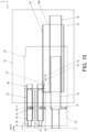
FIG. 10 is a diagram showing the slide rail mechanism applicable to the rack with the first carried object being located at the extended position, and the second carried object being moved relative to the first carried object by a predetermined extension distance according to the embodiment of the present invention; -
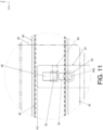
FIG. 11 is an enlarged view of an area A ofFIG. 10 ; -
FIG. 12 is a diagram showing the slide rail mechanism applicable to the rack with the first carried object being located at the retracted position, and the second carried object being moved relative to the first carried object along the opening direction to an extended position according to the embodiment of the present invention; and -
FIG. 13 is an enlarged view of an area A ofFIG. 12 . - As shown in
FIG. 1 , a slide rail mechanism is applicable to arack 22 according to an embodiment of the present invention. The slide rail mechanism comprises a firstslide rail assembly 24, a secondslide rail assembly 26 and a first carriedobject 28. The firstslide rail assembly 24 is configured to support the first carriedobject 28. For example, the first carriedobject 28 can be an outer casing. The secondslide rail assembly 26 is arranged on the first carriedobject 28. For example, the secondslide rail assembly 26 is arranged at an inner side of the first carried object 28 (the outer casing), and the secondslide rail assembly 26 is configured to support a second carriedobject 30. Preferably, the first carriedobject 28 is formed with apredetermined space 32 for accommodating the second carriedobject 30. - As shown in
FIG. 2 andFIG. 3 , the secondslide rail assembly 26 and the second carriedobject 30 are omitted in the figures. Furthermore, the slide rail mechanism further comprises alocking member 34 movably mounted on the first carriedobject 28. - The first
slide rail assembly 24 comprises afirst rail 36 and asecond rail 38 longitudinally movable relative to thefirst rail 36. Preferably, the firstslide rail assembly 24 further comprises afirst middle rail 40 movably mounted between thefirst rail 36 and thesecond rail 38. In the present embodiment, the X axis is a longitudinal direction (or a length direction or moving direction of the slide rail), the Y axis is a transverse direction (or a lateral direction of the slide rail), and the Z axis is a vertical direction (or a height direction of the slide rail) . Thefirst rail 36 is configured to be mounted to therack 22, and thesecond rail 38 is configured to carry the first carriedobject 28. In addition, thelocking member 34 can be a linkage rod, and a moving direction of thelocking member 34 is a height direction of the first carried object 28 (such as the Z-axis direction). - The
first rail 36 is arranged with a firstauxiliary feature 42. Preferably, thefirst rail 36 is further arranged with a second auxiliary feature 44 (as shown inFIG. 3 ). - Preferably, the first
slide rail assembly 24 further comprises abracket 46. Thefirst rail 36 is mounted to therack 22 through thebracket 46. Thebracket 46 is connected (such as fixedly connected) to thefirst rail 36 and can be seen as a portion of thefirst rail 36. - Preferably, the first
auxiliary feature 42 and the secondauxiliary feature 44 are arranged on thebracket 46 on thefirst rail 36. Thebracket 46 has afirst end part 46a and asecond end part 46b opposite to each other, such as a front end part and a rear end part. The firstauxiliary feature 42 and the secondauxiliary feature 44 are arranged adjacent to thefirst end part 46a of thebracket 46, but the present invention is not limited thereto. - Preferably, the first
auxiliary feature 42 and the secondauxiliary feature 44 are protrusions, and the firstauxiliary feature 42 and the secondauxiliary feature 44 are spaced apart from each other by a longitudinal distance along the longitudinal direction. - Preferably, the first
auxiliary feature 42 and the secondauxiliary feature 44 respectively have a first guiding section G1 and a second guiding section G2 corresponding to each other. Each of the first guiding section G1 and the second guiding section G2 has an inclined surface or an arc surface, but the present invention is not limited thereto. - Preferably, the first carried
object 28 comprises a plurality of walls. In the present embodiment, the first carriedobject 28 comprises a predetermined wall 48 (or a side wall). Thepredetermined wall 48 has a first side L1 and a second side L2 opposite to each other, such as an outer side and an inner side, but the present invention is not limited thereto. - Preferably, the first side L1 of the
predetermined wall 48 is connected to thesecond rail 38, and thepredetermined space 32 is formed adjacent to the second side L2. - Preferably, the locking
member 34 is arranged with apredetermined part 50 and a lockingpart 52. - Preferably, the locking
member 34 is movably mounted to the second side L2 of thepredetermined wall 48 of the first carriedobject 28. Anextension section 50a of thepredetermined part 50 of the lockingmember 34 is configured to penetrate through thepredetermined wall 48 to extend to the first side L1 (as shown inFIG. 2 ). - Preferably, the
predetermined wall 48 is formed with a limitingstructure 54, such as an oval hole (as shown inFIG. 2 ), but the present invention is not limited thereto. Theextension section 50a of thepredetermined part 50 is inserted into the limitingstructure 54 of thepredetermined wall 48, such that the lockingmember 34 is movable relative to the first carriedobject 28 within a limited range. - As shown in
FIG. 4 , the secondslide rail assembly 26 comprises athird rail 56 and afourth rail 58 longitudinally movable relative to thethird rail 56. Thethird rail 56 is configured to be mounted to the second side L2 of thepredetermined wall 48 of the first carriedobject 28, and thefourth rail 58 is configured to carry the second carriedobject 30. - Preferably, the
third rail 56 has a first side L1' and a second side L2' opposite to each other, such as an outer side and an inner side, but the present invention is not limited thereto. The first side L1' of thethird rail 56 is connected to the second side L2 of the first carriedobject 28, and the second side L2' of thethird rail 56 is adjacent to thefourth rail 58. Thethird rail 56 is formed with an auxiliary space 60 (such as a through hole) communicating the first side L1' and the second side L2' of thethird rail 56. Theauxiliary space 60 is configured to allow the lockingpart 52 of the lockingmember 34 to pass through thethird rail 56 from the first side L1' of thethird rail 56 to the second side L2' of thethird rail 56. - Preferably, the second
slide rail assembly 26 further comprises a secondmiddle rail 62 movably mounted between thethird rail 56 and thefourth rail 58, and the secondmiddle rail 62 has a blockingfeature 64 configured to interact with the lockingpart 52 of the lockingmember 34. In the present embodiment, the blockingfeature 64 is a protrusion, but the present invention is not limited thereto. - As shown in
FIG. 5 andFIG. 6 , the first carriedobject 28 is mounted with a plurality of secondslide rail assemblies 26. The secondslide rail assemblies 26 have substantially identical structural configuration. Thefourth rail 58 of each of the secondslide rail assemblies 26 is configured to carry the respective second carriedobject 30. In addition, the lockingpart 52 of the lockingmember 34 passes through theauxiliary space 60 of thethird rail 56 to be adjacent to the fourth rail 58 (and the second middle rail 62). - When the
second rail 38 is located at a retracted position R relative to thefirst rail 36, the firstauxiliary feature 42 is configured to support the predetermined part 50 (theextension section 50a of the predetermined part 50), such that the lockingmember 34 is positioned at a first predetermined position K1. - Preferably, when the locking
member 34 is located at the first predetermined position K1, the lockingpart 52 of the lockingmember 34 is not aligned with the blockingfeature 64 of the secondmiddle rail 62 along the longitudinal direction. For example, a vertical position of the lockingpart 52 of the lockingmember 34 along the vertical direction does not correspond to a vertical position of the blockingfeature 64 of the secondmiddle rail 62 along the vertical direction (a transverse position of the lockingpart 52 of the lockingmember 34 along the transverse direction corresponds to a transverse position of the blockingfeature 64 of the secondmiddle rail 62 along the transverse direction). - Preferably, when the
second rail 38 is located at the retracted position R relative to thefirst rail 36, and when thefourth rail 58 and the secondmiddle rail 62 are retracted relative to thethird rail 56, the lockingpart 52 of the lockingmember 34 and the blockingfeature 64 of the secondmiddle rail 62 are spaced apart from each other by a predetermined longitudinal distance M along the longitudinal direction (as shown inFIG. 5 ). - As shown in
FIG. 5 ,FIG. 7 ,FIG. 8 andFIG. 9 , during a process of thesecond rail 38 being moved relative to thefirst rail 36 from the retracted position R along an opening direction D1 to an extended position E (as shown inFIG. 9 ), the firstauxiliary feature 42 no longer supports thepredetermined part 50, such that the lockingmember 34 is moved from the first predetermined position K1 along a predetermined height direction H (as shown inFIG. 5 ) to a second predetermined position K2 (as shown inFIG. 7 andFIG. 8 ) . As such, the lockingpart 52 of the lockingmember 34 is configured to prevent thefourth rail 58 from being moved along the opening direction D1 in order to limit a moving distance of the second carriedobject 30 relative to the first carriedobject 28 along the opening direction D1. - Preferably, in the present embodiment, the locking
part 52 of the lockingmember 34 is configured to block a moving path of the blockingfeature 64 of the secondmiddle rail 62 along the opening direction D1, in order to prevent thefourth rail 58 from being moved along the opening direction D1. Specifically, when the lockingmember 34 is located at the second predetermined position K2, the lockingpart 52 of the lockingmember 34 is aligned with the blockingfeature 64 of the secondmiddle rail 62 along the longitudinal direction. Thereby, the secondmiddle rail 62 is configured to indirectly prevent thefourth rail 58 from being moved along the opening direction D1 (for example, a synchronization mechanism is provided between the secondmiddle rail 62 and the fourth rail 58), in order to limit the moving distance of the second carriedobject 30 relative to the first carriedobject 28 along the opening direction D1. Moreover, in an alternative embodiment, the secondslide rail assembly 26 only comprises thethird rail 56 and the fourth rail 58 (that is, the secondslide rail assembly 26 does not comprise the second middle rail 62), and thefourth rail 58 is configured to carry the second carriedobject 30 and has a blocking feature. When the lockingmember 34 is located at the second predetermined position K2, the lockingpart 52 of the lockingmember 34 is aligned with the blocking feature of thefourth rail 58 along the longitudinal direction (a vertical position of the lockingpart 52 of the lockingmember 34 along the vertical direction corresponds to a vertical position of the blocking feature of thefourth rail 58 along the vertical direction, and a transverse position of the lockingpart 52 of the lockingmember 34 along the transverse direction corresponds to a transverse position of the blocking feature of thefourth rail 58 along the transverse direction), such that the lockingmember 34 is configured to directly block a moving path of thefourth rail 58 along the opening direction D1, in order to limit the moving distance of the second carriedobject 30 relative to the first carriedobject 28 along the opening direction D1. - Preferably, during the process of the
second rail 38 being moved relative to thefirst rail 36 from the retracted position R along the opening direction D1 to the extended position E (as shown inFIG. 9 ), the second guiding section G2 of the secondauxiliary feature 44 is configured to contact and guide the predetermined part 50 (theextension section 50a of the predetermined part 50) of the lockingmember 34 to move the lockingmember 34 from the first predetermined position K1 (as shown in theFIG. 5 ) to the second predetermined position K2 (as shown inFIG. 7 andFIG. 8 ) . On the other hand, the lockingmember 34 can also be moved down to the second predetermined position K2 due to gravity. - As shown in
FIG. 9 ,FIG. 10 andFIG. 11 , when thesecond rail 38 is located at the extended position E relative to thefirst rail 36 and when the lockingmember 34 is located at the second predetermined position K2 (as shown inFIG. 9 ), the lockingpart 52 of the lockingmember 34 and the blockingfeature 64 of the secondmiddle rail 62 are aligned with each other along the longitudinal direction to block each other (as shown inFIG. 10 andFIG. 11 ), so as to indirectly prevent thefourth rail 58 from being moved along the opening direction D1, in order to limit the moving distance of the second carriedobject 30 relative to the first carriedobject 28 along the opening direction D1. In the present embodiment, the second carriedobject 30 is movable relative to the first carriedobject 28 from a predetermined retracted position R' (as shown inFIG. 9 ) along the opening direction D1, and only can be pulled out relative to the first carriedobject 28 by a predetermined extension distance Q (as shown inFIG. 10 ). Or, in other embodiments, the second carriedobject 30 is configured to be prevented from being moved relative to the first carriedobject 28 from the predetermined retracted position R' along the opening direction D1. In other words, the second carriedobject 30 cannot be fully opened relative to the first carriedobject 28. - Moreover, during a process of the
second rail 38 being moved relative to thefirst rail 36 from the extended position E (as shown inFIG. 9 andFIG. 10 ) along a retracting direction D2 to the retracted position R (as shown inFIG. 5 andFIG. 6 ), the first guiding section G1 of the firstauxiliary feature 42 is configured to contact and guide the predetermined part 50 (theextension section 50a of the predetermined part 50) of the lockingmember 34 to move the lockingmember 34 from the second predetermined position K2 (as shown in theFIG. 9 andFIG. 10 ) to the first predetermined position K1 (as shown inFIG. 5 andFIG. 6 ). - As shown in
FIG. 12 andFIG. 13 , when thesecond rail 38 is located at the retracted position R relative to thefirst rail 36, the firstauxiliary feature 42 is configured to support thepredetermined part 50 to position the lockingmember 34 at the first predetermined position K1, such that the lockingpart 52 of the lockingmember 34 is not aligned with the blockingfeature 64 of the secondmiddle rail 62 along the longitudinal direction. Therefore, the lockingpart 52 of the lockingmember 34 is not configured to prevent thefourth rail 58 from being moved along the opening direction D1, in order to allow the second carriedobject 30 to be moved relative to the first carriedobject 28 from the predetermined retracted position R' (as shown inFIG. 9 ) along the opening direction D1 to a predetermined extended position, such as a fully extended position E' (as shown inFIG. 12 ). - Therefore, the slide rail mechanism according to the embodiments of the present invention has the following technical features:
- 1. The slide rail mechanism is applicable to a rack, and the locking
member 34 is movably mounted on the first carriedobject 28. - 2. When the
second rail 38 is located at the extended position E relative to thefirst rail 36 and when the lockingmember 34 is located at the second predetermined position K2, the lockingpart 52 of the lockingmember 34 is configured to prevent thefourth rail 58 from being moved along the opening direction D1, so as to limit the moving distance of the second carriedobject 30 relative to the first carriedobject 28 along the opening direction D1. For example, the second carriedobject 30 is configured to be prevented from being moved relative to the first carriedobject 28 from the predetermined retracted position R' (as shown inFIG. 9 ) along the opening direction D1. Or, the second carriedobject 30 is movable relative to the first carriedobject 28 from the predetermined retracted position R' along the opening direction D1, and only can be pulled out relative to the first carriedobject 28 by the predetermined extension distance Q without being fully opened (as shown inFIG. 10 ). For example, the second carriedobject 30 cannot be moved relative to the first carriedobject 28 from the predetermined retracted position R' along the opening direction D1 to the fully extended position E' (as shown inFIG. 12 ). - 3. When the
second rail 38 is located at the retracted position R relative to thefirst rail 36 and when the lockingmember 34 is located at the first predetermined position K1, the lockingpart 52 of the lockingmember 34 is not configured to prevent thefourth rail 58 from being moved along the opening direction D1, in order to allow the second carriedobject 30 to be moved relative to the first carriedobject 28 from the predetermined retracted position R' along the opening direction D1 to the fully extended position E' (as shown inFIG. 12 ).
Claims (11)
- A slide rail mechanism applicable to a rack (22), comprising:a first carried object (28);a first slide rail assembly (24) comprising a first rail (36) and a second rail (38) longitudinally movable relative to the first rail (36), wherein the first rail (36) is configured to be mounted to the rack (22), and the second rail (38) is configured to carry the first carried object (28) ;a second slide rail assembly (26) arranged on the first carried object (28), the second slide rail assembly (26) comprising a third rail (56) and a fourth rail (58) longitudinally movable relative to the third rail (56), wherein the third rail (56) is configured to be mounted to the first carried object (28), and the fourth rail (58) is configured to carry a second carried object (30); and a locking member (34) movably mounted to the first carried object (28);characterized in that:wherein the first rail (36) is arranged with an auxiliary feature (42), and the locking member (34) is arranged with a predetermined part (50) and a locking part (52);wherein when the second rail (38) is located at a retracted position relative to the first rail (36), the auxiliary feature (42) is configured to support the predetermined part (50) to position the locking member (34) at a first predetermined position, such that the locking part (52) of the locking member (34) is not configured to prevent the fourth rail (58) from being moved along an opening direction, in order to allow the second carried object (30) to be moved relative to the first carried object (28) along the opening direction;wherein during a process of the second rail (38) being moved relative to the first rail (36) along the opening direction to an extended position, the locking member (34) is moved from the first predetermined position to a second predetermined position, such that the locking part (52) of the locking member (34) is configured to prevent the fourth rail (58) from being moved along the opening direction, in order to limit a moving distance of the second carried object (30) relative to the first carried object (28) along the opening direction.
- The slide rail mechanism of claim 1, characterized in that the first slide rail assembly (24) further comprises a bracket (46) connected to the first rail (36), and the first rail (36) is configured to be mounted to the rack (22) through the bracket (46).
- The slide rail mechanism of claim 2, characterized in that the auxiliary feature (42) is arranged on the bracket (46) on the first rail (36).
- The slide rail mechanism of claim 2 or 3, characterized in that the first slide rail assembly (24) further comprises a first middle rail (40) movably mounted between the first rail (36) and the second rail (38).
- The slide rail mechanism of any of claims 1-4, characterized in that the first carried object (28) comprises a predetermined wall (48), and the predetermined wall (48) has a first side and a second side opposite to each other; wherein the first side is connected to the second rail (38), and a predetermined space is formed adjacent to the second side in order to accommodate the second carried object (30).
- The slide rail mechanism of claim 5, characterized in that the locking member (34) is movably mounted to the second side of the predetermined wall (48) of the first carried object (28); wherein the predetermined part (50) of the locking member (34) is configured to penetrate through the predetermined wall (48) to extend to the first side, and the locking part (52) of the locking member (34) is configured to pass through the third rail (56) to be adjacent to the fourth rail (58).
- The slide rail mechanism of claim 6, characterized in that the second slide rail assembly (26) further comprises a second middle rail (62) movably mounted between the third rail (56) and the fourth rail (58), and the second middle rail (62) has a blocking feature (64) ; wherein when the locking member (34) is located at the second predetermined position, the locking part (52) of the locking member (34) is configured to block a moving path of the blocking feature (64) along the opening direction.
- The slide rail mechanism of claim 7, characterized in that when the second rail (38) is located at the retracted position relative to the first rail (36) and when the fourth rail (58) is retracted relative to the third rail (56), the locking part (52) of the locking member (34) and the blocking feature (64) of the second middle rail (62) are spaced apart from each other by a predetermined longitudinal distance along the longitudinal direction.
- The slide rail mechanism of any of claims 6-8, characterized in that the predetermined wall (48) is formed with a limiting structure (54), and the predetermined part (50) of the locking member (34) is inserted into the limiting structure (54) of the predetermined wall (48).
- The slide rail mechanism of any of claims 6-9, characterized in that a moving direction of the locking member (34) is a height direction of the first carried object (28).
- The slide rail mechanism of any of claims 1-10, characterized in that during the process of the second rail (38) being moved relative to the first rail (36) along the opening direction to the extended position, the auxiliary feature (42) does not support the predetermined part (50).
Applications Claiming Priority (1)
| Application Number | Priority Date | Filing Date | Title |
|---|---|---|---|
| TW113100400A TWI870191B (en) | 2024-01-03 | 2024-01-03 | Slide rail mechanism |
Publications (2)
| Publication Number | Publication Date |
|---|---|
| EP4581983A1 true EP4581983A1 (en) | 2025-07-09 |
| EP4581983B1 EP4581983B1 (en) | 2026-03-18 |
Family
ID=92816643
Family Applications (1)
| Application Number | Title | Priority Date | Filing Date |
|---|---|---|---|
| EP24200753.2A Active EP4581983B1 (en) | 2024-01-03 | 2024-09-17 | Slide rail mechanism |
Country Status (4)
| Country | Link |
|---|---|
| US (1) | US20250213040A1 (en) |
| EP (1) | EP4581983B1 (en) |
| JP (1) | JP7827799B2 (en) |
| TW (1) | TWI870191B (en) |
Citations (4)
| Publication number | Priority date | Publication date | Assignee | Title |
|---|---|---|---|---|
| US4925257A (en) | 1988-12-27 | 1990-05-15 | Timberline Supply Ltd. | Safety lock system for cabinet with multiple drawers |
| US6722749B1 (en) | 2001-08-14 | 2004-04-20 | Snap-On Technologies, Inc. | Drawer open position controller |
| US20120187816A1 (en) * | 2011-01-21 | 2012-07-26 | King Slide Works Co., Ltd. | Interlock device for slide assembly |
| US10750863B2 (en) * | 2017-07-20 | 2020-08-25 | Black Pearl Woodworks LLC | Drawer system having primary and concealed drawers |
Family Cites Families (14)
| Publication number | Priority date | Publication date | Assignee | Title |
|---|---|---|---|---|
| US1993477A (en) * | 1934-09-14 | 1935-03-05 | Gen Fireproofing Co | Card cabinet |
| JP4456251B2 (en) * | 2000-10-02 | 2010-04-28 | クリナップ株式会社 | Kitchen furniture storage structure |
| AT502097B1 (en) * | 2005-07-12 | 2010-01-15 | Blum Gmbh Julius | FURNITURE EQUIPMENT FOR DRAWERS |
| JP2009022543A (en) * | 2007-07-20 | 2009-02-05 | Okamura Corp | Multi-stage cabinet |
| US9173488B1 (en) * | 2012-12-10 | 2015-11-03 | Thomas J. Bello | Combination drawer assembly |
| TWI598026B (en) * | 2015-09-18 | 2017-09-01 | King Slide Works Co Ltd | Slide rail assembly with interlock device |
| TWI629025B (en) * | 2016-07-29 | 2018-07-11 | 川湖科技股份有限公司 | Slide rail assembly |
| US10524587B2 (en) * | 2016-08-17 | 2020-01-07 | The Hillman Group, Inc. | Cabinet with telescoping trays for fastener bins |
| JP6881849B2 (en) * | 2019-03-11 | 2021-06-02 | Necプラットフォームズ株式会社 | Electronic device support frame and cable support method for electronic devices |
| AT524352B1 (en) * | 2020-09-28 | 2022-07-15 | Fulterer Ag & Co Kg | Locking device for drawers |
| JP7501912B2 (en) * | 2021-02-18 | 2024-06-18 | 野村ユニソン株式会社 | Cabinet and drawer locking mechanisms |
| CN115868749A (en) * | 2021-09-30 | 2023-03-31 | 合肥美的电冰箱有限公司 | Storing cabinet |
| TWI806513B (en) * | 2022-03-23 | 2023-06-21 | 緯創資通股份有限公司 | Casing assembly and electronic device including the same |
| TWI842394B (en) * | 2023-02-14 | 2024-05-11 | 川湖科技股份有限公司 | Slide rail mechanism |
-
2024
- 2024-01-03 TW TW113100400A patent/TWI870191B/en active
- 2024-09-03 US US18/823,444 patent/US20250213040A1/en active Pending
- 2024-09-17 EP EP24200753.2A patent/EP4581983B1/en active Active
- 2024-09-26 JP JP2024166840A patent/JP7827799B2/en active Active
Patent Citations (4)
| Publication number | Priority date | Publication date | Assignee | Title |
|---|---|---|---|---|
| US4925257A (en) | 1988-12-27 | 1990-05-15 | Timberline Supply Ltd. | Safety lock system for cabinet with multiple drawers |
| US6722749B1 (en) | 2001-08-14 | 2004-04-20 | Snap-On Technologies, Inc. | Drawer open position controller |
| US20120187816A1 (en) * | 2011-01-21 | 2012-07-26 | King Slide Works Co., Ltd. | Interlock device for slide assembly |
| US10750863B2 (en) * | 2017-07-20 | 2020-08-25 | Black Pearl Woodworks LLC | Drawer system having primary and concealed drawers |
Also Published As
| Publication number | Publication date |
|---|---|
| JP7827799B2 (en) | 2026-03-10 |
| TWI870191B (en) | 2025-01-11 |
| TW202527855A (en) | 2025-07-16 |
| EP4581983B1 (en) | 2026-03-18 |
| US20250213040A1 (en) | 2025-07-03 |
| JP2025106183A (en) | 2025-07-15 |
Similar Documents
| Publication | Publication Date | Title |
|---|---|---|
| US5772294A (en) | Multi-drawer cabinet having a drawer lock-out mechanism | |
| US7249814B2 (en) | Slide rail | |
| JP3987160B2 (en) | Interlock assembly | |
| US12203292B2 (en) | Slide rail mechanism | |
| EP4741611A1 (en) | Slide rail mechanism | |
| WO2018033242A1 (en) | Drawer rack for a cabinet | |
| EP4570126A1 (en) | Slide rail assembly | |
| US12345075B2 (en) | Furniture assembly and interlock kit thereof | |
| EP3531872B1 (en) | Furniture | |
| EP4581983B1 (en) | Slide rail mechanism | |
| JP2024115507A (en) | Slide Rail Mechanism | |
| EP4403732A1 (en) | Slide rail mechanism | |
| US12467285B2 (en) | Pull-out locking device for drawers | |
| GB2063355A (en) | Interlocking drawers | |
| EP4461160A1 (en) | Furniture assembly | |
| US12369711B2 (en) | Slide rail mechanism | |
| EP4420560A1 (en) | Slide rail mechanism | |
| CN120240808A (en) | Slide rail mechanism | |
| EP4401521A1 (en) | Slide rail assembly | |
| EP4616761B1 (en) | Slide rail mechanism | |
| US20260132656A1 (en) | Slide rail mechanism | |
| EP4647568A1 (en) | Adjusting device and related slide rail mechanism | |
| AT16625U1 (en) | Arrangement for moving a drawer system | |
| CN118452646A (en) | Slide rail mechanism | |
| JP2026085216A (en) | Slide rail mechanism |
Legal Events
| Date | Code | Title | Description |
|---|---|---|---|
| PUAI | Public reference made under article 153(3) epc to a published international application that has entered the european phase |
Free format text: ORIGINAL CODE: 0009012 |
|
| STAA | Information on the status of an ep patent application or granted ep patent |
Free format text: STATUS: REQUEST FOR EXAMINATION WAS MADE |
|
| 17P | Request for examination filed |
Effective date: 20250415 |
|
| AK | Designated contracting states |
Kind code of ref document: A1 Designated state(s): AL AT BE BG CH CY CZ DE DK EE ES FI FR GB GR HR HU IE IS IT LI LT LU LV MC ME MK MT NL NO PL PT RO RS SE SI SK SM TR |
|
| GRAP | Despatch of communication of intention to grant a patent |
Free format text: ORIGINAL CODE: EPIDOSNIGR1 |
|
| STAA | Information on the status of an ep patent application or granted ep patent |
Free format text: STATUS: GRANT OF PATENT IS INTENDED |
|
| INTG | Intention to grant announced |
Effective date: 20251201 |
|
| GRAS | Grant fee paid |
Free format text: ORIGINAL CODE: EPIDOSNIGR3 |
|
| GRAA | (expected) grant |
Free format text: ORIGINAL CODE: 0009210 |
|
| STAA | Information on the status of an ep patent application or granted ep patent |
Free format text: STATUS: THE PATENT HAS BEEN GRANTED |
|
| AK | Designated contracting states |
Kind code of ref document: B1 Designated state(s): AL AT BE BG CH CY CZ DE DK EE ES FI FR GB GR HR HU IE IS IT LI LT LU LV MC ME MK MT NL NO PL PT RO RS SE SI SK SM TR |
|
| REG | Reference to a national code |
Ref country code: CH Ref legal event code: F10 Free format text: ST27 STATUS EVENT CODE: U-0-0-F10-F00 (AS PROVIDED BY THE NATIONAL OFFICE) Effective date: 20260318 Ref country code: GB Ref legal event code: FG4D |
|
| REG | Reference to a national code |
Ref country code: IE Ref legal event code: FG4D |
|
| REG | Reference to a national code |
Ref country code: DE Ref legal event code: R096 Ref document number: 602024003283 Country of ref document: DE |