EP4581965A2 - Aerosol provision device - Google Patents
Aerosol provision device Download PDFInfo
- Publication number
- EP4581965A2 EP4581965A2 EP25178635.6A EP25178635A EP4581965A2 EP 4581965 A2 EP4581965 A2 EP 4581965A2 EP 25178635 A EP25178635 A EP 25178635A EP 4581965 A2 EP4581965 A2 EP 4581965A2
- Authority
- EP
- European Patent Office
- Prior art keywords
- heater component
- support
- insulating member
- coil
- axis
- Prior art date
- Legal status (The legal status is an assumption and is not a legal conclusion. Google has not performed a legal analysis and makes no representation as to the accuracy of the status listed.)
- Pending
Links
Images





Classifications
-
- A—HUMAN NECESSITIES
- A24—TOBACCO; CIGARS; CIGARETTES; SIMULATED SMOKING DEVICES; SMOKERS' REQUISITES
- A24F—SMOKERS' REQUISITES; MATCH BOXES; SIMULATED SMOKING DEVICES
- A24F40/00—Electrically operated smoking devices; Component parts thereof; Manufacture thereof; Maintenance or testing thereof; Charging means specially adapted therefor
- A24F40/40—Constructional details, e.g. connection of cartridges and battery parts
- A24F40/46—Shape or structure of electric heating means
-
- A—HUMAN NECESSITIES
- A24—TOBACCO; CIGARS; CIGARETTES; SIMULATED SMOKING DEVICES; SMOKERS' REQUISITES
- A24F—SMOKERS' REQUISITES; MATCH BOXES; SIMULATED SMOKING DEVICES
- A24F40/00—Electrically operated smoking devices; Component parts thereof; Manufacture thereof; Maintenance or testing thereof; Charging means specially adapted therefor
- A24F40/20—Devices using solid inhalable precursors
-
- A—HUMAN NECESSITIES
- A24—TOBACCO; CIGARS; CIGARETTES; SIMULATED SMOKING DEVICES; SMOKERS' REQUISITES
- A24F—SMOKERS' REQUISITES; MATCH BOXES; SIMULATED SMOKING DEVICES
- A24F40/00—Electrically operated smoking devices; Component parts thereof; Manufacture thereof; Maintenance or testing thereof; Charging means specially adapted therefor
- A24F40/40—Constructional details, e.g. connection of cartridges and battery parts
- A24F40/46—Shape or structure of electric heating means
- A24F40/465—Shape or structure of electric heating means specially adapted for induction heating
-
- A—HUMAN NECESSITIES
- A24—TOBACCO; CIGARS; CIGARETTES; SIMULATED SMOKING DEVICES; SMOKERS' REQUISITES
- A24F—SMOKERS' REQUISITES; MATCH BOXES; SIMULATED SMOKING DEVICES
- A24F40/00—Electrically operated smoking devices; Component parts thereof; Manufacture thereof; Maintenance or testing thereof; Charging means specially adapted therefor
- A24F40/50—Control or monitoring
- A24F40/51—Arrangement of sensors
-
- H—ELECTRICITY
- H05—ELECTRIC TECHNIQUES NOT OTHERWISE PROVIDED FOR
- H05B—ELECTRIC HEATING; ELECTRIC LIGHT SOURCES NOT OTHERWISE PROVIDED FOR; CIRCUIT ARRANGEMENTS FOR ELECTRIC LIGHT SOURCES, IN GENERAL
- H05B6/00—Heating by electric, magnetic or electromagnetic fields
- H05B6/02—Induction heating
- H05B6/10—Induction heating apparatus, other than furnaces, for specific applications
- H05B6/105—Induction heating apparatus, other than furnaces, for specific applications using a susceptor
- H05B6/108—Induction heating apparatus, other than furnaces, for specific applications using a susceptor for heating a fluid
-
- H—ELECTRICITY
- H05—ELECTRIC TECHNIQUES NOT OTHERWISE PROVIDED FOR
- H05B—ELECTRIC HEATING; ELECTRIC LIGHT SOURCES NOT OTHERWISE PROVIDED FOR; CIRCUIT ARRANGEMENTS FOR ELECTRIC LIGHT SOURCES, IN GENERAL
- H05B6/00—Heating by electric, magnetic or electromagnetic fields
- H05B6/02—Induction heating
- H05B6/36—Coil arrangements
-
- A—HUMAN NECESSITIES
- A24—TOBACCO; CIGARS; CIGARETTES; SIMULATED SMOKING DEVICES; SMOKERS' REQUISITES
- A24D—CIGARS; CIGARETTES; TOBACCO SMOKE FILTERS; MOUTHPIECES OF CIGARS OR CIGARETTES; MANUFACTURE OF TOBACCO SMOKE FILTERS OR MOUTHPIECES
- A24D1/00—Cigars; Cigarettes
- A24D1/20—Cigarettes specially adapted for simulated smoking devices
-
- A—HUMAN NECESSITIES
- A24—TOBACCO; CIGARS; CIGARETTES; SIMULATED SMOKING DEVICES; SMOKERS' REQUISITES
- A24F—SMOKERS' REQUISITES; MATCH BOXES; SIMULATED SMOKING DEVICES
- A24F40/00—Electrically operated smoking devices; Component parts thereof; Manufacture thereof; Maintenance or testing thereof; Charging means specially adapted therefor
- A24F40/70—Manufacture
-
- B—PERFORMING OPERATIONS; TRANSPORTING
- B29—WORKING OF PLASTICS; WORKING OF SUBSTANCES IN A PLASTIC STATE IN GENERAL
- B29K—INDEXING SCHEME ASSOCIATED WITH SUBCLASSES B29B, B29C OR B29D, RELATING TO MOULDING MATERIALS OR TO MATERIALS FOR MOULDS, REINFORCEMENTS, FILLERS OR PREFORMED PARTS, e.g. INSERTS
- B29K2071/00—Use of polyethers, e.g. PEEK, i.e. polyether-etherketone or PEK, i.e. polyetherketone or derivatives thereof, as moulding material
Definitions
- the present invention relates to a support for a heater component of an aerosol provision device and an aerosol provision device including the support.
- the present invention also relates to an aerosol provision device, an aerosol provision system and an article comprising aerosol generating material.
- Smoking articles such as cigarettes, cigars and the like burn tobacco during use to create tobacco smoke. Attempts have been made to provide alternatives to these articles that burn tobacco by creating products that release compounds without burning. Examples of such products are heating devices which release compounds by heating, but not burning, the material.
- the material may be for example tobacco or other non-tobacco products, which may or may not contain nicotine.
- a support for a heater component of an aerosol provision device wherein the support defines an axis and is configured to engage an end of the heater component to hold the heater component substantially parallel to the axis at a predetermined distance from a coil, and wherein the support defines a channel to receive a wire of a temperature sensor, the channel defining an opening into a space between the heater component and the coil.
- an aerosol provision device comprising:
- an aerosol provision device comprising:
- an aerosol provision device comprising:
- an aerosol provision device comprising:
- Apparatus that heats aerosol generating material to volatilise at least one component of the aerosol generating material, typically to form an aerosol which can be inhaled, without burning or combusting the aerosol generating material.
- Such apparatus is sometimes described as an "aerosol generating device", an “aerosol provision device”, a “heat-not-burn device”, a “tobacco heating product device” or a “tobacco heating device” or similar.
- e-cigarette devices which typically vaporise an aerosol generating material in the form of a liquid, which may or may not contain nicotine.
- An aerosol provision device can receive an article comprising aerosol generating material for heating.
- An "article” in this context is a component that includes or contains in use the aerosol generating material, which is heated to volatilise the aerosol generating material, and optionally other components in use.
- a user may insert the article into the aerosol provision device before it is heated to produce an aerosol, which the user subsequently inhales.
- the article may be, for example, of a predetermined or specific size that is configured to be placed within a heating chamber of the device which is sized to receive the article.
- a first aspect of the present disclosure defines a support for a heater component (such as a susceptor) of an aerosol provision device.
- a susceptor is an electrically conducting object, which is heated via electromagnetic induction.
- An article comprising aerosol generating material can be received within the heater component. Once heated, the heater component transfers heat to the aerosol generating material, which releases the aerosol.
- the device can monitor the temperature of the heater component in one or more locations, as it is being heated. This may be useful because the aerosol generating material may need to be heated to a specific temperature. For example, if the temperature of the heater component is too high, the aerosol generating material may overheat, which can impact the taste/flavour of the aerosol. If the temperature of the heater component is too low, the volume of aerosol generated may be too low. Accordingly, it may be useful to control and monitor the temperature of the heater component during heating.
- one or more temperature sensors may be in contact with, or positioned near, the heater component.
- the temperature sensor may be a thermocouple, for example.
- One or more wires may connect the temperature sensor to other electronic circuitry within the aerosol provision device, and the wires must therefore be routed from the heater component, to another location within the device.
- the heater component may be a susceptor, and the heater component may be heated by a coil (such as an inductor coil).
- a coil such as an inductor coil
- An inductor coil is configured to generate a varying magnetic field.
- a susceptor is heatable by penetration with the varying magnetic field.
- the heater component may be surrounded by one or more components, such as an insulating member which can be arranged coaxially with the heater component.
- the insulating member can help insulate other components of the device from the heat generated by the heater component.
- the insulating member may also support one or more coils which are positioned around, and spaced apart from, the heater component.
- the wires from the temperature sensors are routed through a surface of the insulating member.
- one or more through holes may be formed through the insulating member, and the wires passed through the through hole.
- the through hole can weaken the structural integrity of the insulating member.
- the insulating member is more prone to damage.
- the hole can also reduce the insulative effect provided by the insulating member. Thus, heat can escape from the space between the heater component and the insulating member.
- the present invention relates to a support which defines a channel through which the wire of a temperature sensor can pass.
- the support is an element which holds the heater component in place within the device.
- the channel formed in the support defines an opening into a space between the heater component and coil/insulating member. This means that the wire does not need to be routed through the insulating member so that its structural integrity is not compromised.
- One or more wires may be routed through the channel.
- the support also known as a "cleanout tube”
- the support defines an axis and is configured to engage an end of the heater component to hold the heater component substantially parallel to the axis at a predetermined distance from a coil.
- the support therefore holds the heater component in place within the device, relative to the coil.
- the wire can therefore be routed along the heater component (generally in the direction of the axis), and through the channel so that it can extend out of the space between the heater component and the coil.
- the channel may extend substantially parallel to the axis.
- the channel is formed through a portion of the support in a direction that is substantially parallel to the axis.
- the wire once received in the channel, therefore extends in a direction substantially parallel to the axis. This construction can be easier to manufacture, and also minimises length of wire used because it defines the shortest route into the space between the heater component and the coil/insulating member. In other examples the channel may not be parallel to the axis.
- the channel may be open along its length. In other words, the channel may be open around its perimeter. In contrast, a channel that is closed around its perimeter would be a through hole formed through a portion of the support.
- a channel which is open along its length can be easily manufactured and may allow the device to be assembled quicker. For example, the wire can be slotted into the channel, rather than requiring the wire to be threaded through a hole.
- the channel can have a depth which is measured in a direction perpendicular to the axis.
- the channel may therefore define a notch formed in a portion of the support.
- the channel may have a depth of less than about 5mm, or less than about 3mm.
- the channel has a depth of less than about 2mm, such as about 1.7mm. If the channel is too deep, then heat may more easily escape from the space between the heater component and coil. If the channel is too shallow, then the wire may need to be angled with respect to the axis and heater component, which may bend or break the wire. The above dimensions provide a good balance between these considerations.
- the channel can have a width which is measured in a direction perpendicular to the axis and the depth.
- the channel may have a width of less than about 2mm, or less than about 1mm.
- the channel has a width of about 0.9mm. If the channel is too wide, then heat may more easily escape from the space between the heater component and coil.
- the support may comprise a first portion, and the channel may be formed through the first portion.
- the first portion may have a first cross section, and may be arranged generally perpendicular to the axis.
- the first portion may be substantially circular in cross section, although other cross-sectional shapes are possible.
- the first portion may have a perimeter which extends around the axis.
- the first portion may have a first depth, measured in a direction parallel to the axis.
- the channel therefore has a length equal to the first depth if the channel is formed parallel to the axis, or has a length greater than the first depth if the channel is not parallel to the axis.
- the channel is a notch at an outer perimeter of the first portion. In other examples however, the channel is closed around its perimeter such that a through hole is formed through the first portion.
- the inner diameter of the though hole can be substantially the same as the outer diameter of the wire, which thereby reduces heat loss from the heater component.
- the second portion may not comprise a channel. Instead, the wire may be routed around the second portion.
- the resilient member encloses/encircles the wire.
- the resilient member extends around the wire.
- the wire passes inside the "O". This arrangement can help keep the wires taught so that they are less likely to be damaged, and/or can hold the wires in the channel. Holding the wires in the channel can help stop the temperature sensor from being pulled away from the surface of the heater component.
- the second aspect of the present disclosure defines an aerosol provision device comprising a support as described above.
- the device further comprises a heater component engaged with the support at one end, and a coil extending around the heater component, where the coil is configured to heat the heater component (via a magnetic field, for example).
- the device further comprises a temperature sensor for sensing the temperature of the heater component, where the temperature sensor is positioned in a space between the coil and the heater component.
- the device further comprises a wire positioned in the channel of the support and connected to the temperature sensor.
- the device may define a longitudinal axis that is substantially parallel to the axis of the support.
- the device may define a proximal end, and a distal end.
- the proximal end of the device may be held closer to a user's mouth than the distal end.
- aerosol may be drawn towards the proximal end of the device.
- the support engages the distal end of the heater component.
- the device may further comprise an insulating member.
- the support may comprise a first portion, where the channel is formed through the first portion.
- the insulating member may surround the heater component and abut at least part of the first portion of the support, thereby to position the insulating member at a predetermined radial distance outward from the heater component.
- the insulating member surrounds the first portion of the support.
- the insulating member is arranged between the heater component and the coil, and is spaced apart from the axis by a first distance.
- a perimeter of the first portion is spaced apart from the axis by a second distance.
- the first distance may be substantially equal to the second distance.
- the first distance may be slightly greater than the second distance, so that the first portion may fit inside the hollow insulating member.
- the perimeter of the first portion may abut the inner surface of the insulating member.
- the outer edge of the resilient member may be spaced apart from the axis by a third distance, the third distance being substantially equal to the first distance.
- the resilient member may abut the inner surface of the insulating member.
- the device comprises a first coil and a second coil.
- the first coil may be used to heat a first portion of the heater component
- the second coil may be used to heat a second portion of the heater component.
- the device comprises a first temperature sensor arranged to sense a temperature of the first portion of the heater component, and a second temperature sensor arranged to sense a temperature of the second portion of the heater component.
- Each temperature sensor may be associated with two wires, and the support may define four channels, where each channel receives a wire.
- the device may comprise a second temperature sensor for sensing the temperature of the heater component, wherein the second temperature sensor is positioned in the space between the coil and the heater component and a second wire is connected to the second temperature sensor, wherein the support defines a second channel to receive the second wire.
- the temperature sensor is in contact with the heater component. This allows for a more accurate reading of the heater component temperature.
- a fourth aspect of the present disclosure relates to the positioning of a heater component in relation to first and second supports.
- the first and second supports engage opposite ends of the heater component and hold the heater component in place within the aerosol provision device.
- One or more coils are positioned away from the heater component by a predetermined distance. In some arrangements, the one or more coils extend around the heater component.
- the heater component may be known as a susceptor, in some examples.
- the first and second supports ensure that the heater component is adequately positioned in relation to the one or more coils. By keeping the distance between the heater component and coil constant over time, the heater component can be heated effectively each time the device is used. Furthermore, because the first and second supports are not integral with the heater component, heat is transferred to the first and second supports at a slower rate. This can help insulate other components of the device from the heated heater component. In other examples, however, the first and second supports are integral with the heater component. For example, they may be moulded together. While this may increase the rate at which heat conducts away from the heater component, it can more robustly hold the heater component in place.
- the first and second supports may comprise a plastics material.
- they may be entirely, or partially made from one or more plastics materials.
- the portion of the support which engages the heater component comprises the plastics material.
- Plastics are good thermal insulators, are relatively inexpensive, are lightweight, and can easily be moulded into the required shape to engage the heater component.
- the plastics material comprises polyether ether ketone (PEEK).
- PEEK is a particularly suitable material for the first and second supports because it has a thermal conductivity of about 0.32W/mK, a melting point of about 343°C and is not electrically conductive, so will not generate heat as a result of the coils.
- the PEEK is Victrex ® PEEK 450G.
- the first and second supports have a melting point of greater than about 300°C.
- the first and second supports have a melting point of greater than about 340°C.
- the one or more coils are configured to heat the heater component to a temperature of between about 240°C and about 280°C.
- the at least one coil may be configured to heat the heater component to a first temperature and the first and second supports have a melting point of a second temperature, wherein the second temperature is greater than the first temperature by at least about 60 °C. This ensures that the first and second supports remain structurally stable, and do not begin to weaken as the temperature of heater component increases.
- the first temperature is 250°C and the second temperature is 343°C.
- the first temperature is 280°C and the second temperature is 343°C.
- the coils may operate in two modes. In a first mode the heater is heated to a lower temperature than in a second mode.
- the aerosol provision device further comprises an insulating member extending around the heater component, wherein the insulating member is positioned away from the heater component to provide an air gap around the heater component.
- the insulating member may be positioned between the at least one coil and the heater component such that the at least one coil extends around the insulating member.
- the coil may be in contact with the insulating member.
- a further air gap may be provided between the insulating member and the coil.
- Such an arrangement provides a device with improved insulation.
- the specific order of the air gap and the insulating member provides improved insulation from the heated heater component.
- the air gap helps insulate the insulating member from the heat.
- the first and second supports, the air gap and the insulating member help insulate other components of the device from the heat.
- the supports, air gap and insulating member reduce any heating of the coil, electronics, and/or battery by the heater component.
- the insulating member is positioned away from the receptacle/heater component to provide an air gap.
- the inner surface of the insulating member is spaced apart from the outer surface of the heater component. This means that an air gap surrounds the outer surface of the heater component, and the heater component is not in contact with the insulating member in this region. Any contact could provide a thermal bridge along which heat could flow.
- the heater component is elongate and defines an axis, such as a longitudinal axis.
- the insulating member extends around the heater component and the axis in an azimuthal direction.
- the insulating member is therefore positioned radially outward from the heater component, for example the insulating member may be coaxial with the heater component.
- This radial direction is defined as being perpendicular to the axis of the heater component.
- the coil extends around the insulating member and is positioned radially outwards from both the heater component and the insulating member. The coil may be coaxial with the insulating member and the heater component.
- the insulating member is thermally insulating.
- it may comprise a plastics material and may have low thermal conductivity such as a thermal conductivity of less than about 0.5W/mK.
- the plastics material is PEEK, and may therefore be made from the same material as the first and second supports.
- the insulating member may abut at least one of the first support and the second support such that the insulating member is held substantially parallel to the axis.
- the insulating member may extend between the first and second supports such that a first end of the insulating member abuts the first support and a second end of the insulating member abuts the second support.
- the first and second supports may therefore also support the insulating member as well as the heater component, which reduces the number of components in the device.
- the first support may comprise a first resilient member and the resilient member may abut an inner surface of the insulating member.
- the insulating member may therefore extend around a portion of the first support which comprises the first resilient member.
- the resilient member may be an O-ring, for example.
- the resilient member may extend around an outer surface of the first support. When the resilient member abuts the inner surface of the insulating member it can help seal the space between the heater component and insulating member to better insulate the heater component from other components of the device.
- the resilient member may not abut the inner surface of the insulating member, but may nevertheless provide improved insulation when compared to an arrangement without a resilient member.
- the first support may comprise a first portion and a second portion spaced apart from the first portion in a direction parallel to the axis, and wherein the resilient member is arranged between the first and second portions.
- the resilient member can therefore be retained in position along the axis by the first and second portions. In other words, the resilient member cannot move along the axis beyond the first and second portions.
- the second support may comprise a second resilient member and the second resilient member may abut the inner surface of the insulating member, such that the first and second resilient members seal the air gap.
- the insulating member may therefore extend around a portion of the second support which comprises the second resilient member.
- the second resilient member may be an O-ring, for example.
- the second resilient member may extend around an outer surface of the second support. When the second resilient member abuts the inner surface of the insulating member it can help seal the space between the heater component and insulating member to better insulate the heater component from other components of the device.
- the second resilient member may not abut the inner surface of the insulating member, but may nevertheless provide improved insulation when compared to an arrangement without a second resilient member.
- the second support may comprise a third portion and a fourth portion spaced apart from the third portion in a direction parallel to the axis, and wherein the second resilient member is arranged between the third and fourth portions.
- the resilient members may comprise silicone, such as silicone rubber.
- silicone rubber is heat resistant and has good mechanical properties which remain unchanged in a wide range of temperatures. Silicone rubber is also safe for use in aerosol provision devices.
- the silicone rubber is Elastosil TM from Wacker Chemie AG.
- the insulating member can be moulded to the first and/or second supports to help seal the space between the heater component and the insulating member. While this may increase the flow of heat, it can provide a better seal.
- the coil may be substantially helical.
- the coil may be formed from wire, such as Litz wire, which is wound helically around the insulating member.
- the coil may not extend around the heater component, but instead may be arranged differently but nevertheless heat the heater component.
- references to an "outer surface” of an entity means the surface positioned furthest away from the axis of the heater component, in a direction perpendicular to the axis.
- reference to an “inner surface” of an entity means the surface positioned closest to the axis of the heater component, in a direction perpendicular to the axis.
- the coil is positioned away from an outer surface of the heater component by a distance of between about 3mm and about 4mm, the insulating member has a thickness of between about 0.25mm and about 1mm, and the heater component has a thickness of between about 0.025mm and about 0.5mm.
- the coil is positioned away from an outer surface of the heater component by a distance of between about 3mm and about 4mm, the insulating member has a thickness of between about 0.25mm and about 1mm, and the heater component has a thickness of between about 0.025mm and about 0.5mm.
- the coil is positioned away from an outer surface of the heater component by a distance of about 3.25mm, the insulating member has a thickness of about 0.5mm, and the heater component has a thickness of about 0.05mm.
- the coil, the heater component and the insulating member may be coaxial. This arrangement ensures that the heater component is heated effectively, and ensures that the air gap and insulating member provide effective insulation.
- the inner surface of the coil may be in contact with an outer surface of the insulating member.
- the insulating member can support the coil without the need for other components.
- the distance between the inner surface of the coil and the outer surface of the insulating member may be less than about 0. 1mm, for example it may be about 0.05mm.
- the insulating member may have a melting point of greater than about 280 °C, such as greater than about 300 °C, or greater than about 340 °C.
- PEEK has a melting point of 343 °C. Insulating members with such melting points ensure that the insulating member remains rigid/solid when the heater component is heated.
- the device is a tobacco heating device, also known as a heat-not-burn device.
- the coil(s) is/are configured to generate, in use, a varying magnetic field for penetrating at least one heating component/element, to thereby cause induction heating and/or magnetic hysteresis heating of the at least one heating component.
- the or each heating component may be termed a "susceptor”.
- a coil that is configured to generate, in use, a varying magnetic field for penetrating at least one electrically-conductive heating component, to thereby cause induction heating of the at least one electrically-conductive heating component may be termed an "induction coil” or "inductor coil”.
- the device may include the heating component(s), for example electrically-conductive heating component(s), and the heating component(s) may be suitably located or locatable relative to the coil(s) to enable such heating of the heating component(s).
- the heating component(s) may be in a fixed position relative to the coil(s).
- both the device and an article/consumable may comprise at least one respective heating component, for example at least one electrically-conductive heating component, and the coil(s) may be to cause heating of the heating component(s) of each of the device and the article when the article is in the heating zone.
- the coil(s) is/are helical. In some examples, the coil(s) encircles at least a part of a heating zone of the device that is configured to receive aerosol generating material. In some examples, the coil(s) is/are helical coil(s) that encircles at least a part of the heating zone.
- the heating zone may be a receptacle, shaped to receive the aerosol generating material.
- the device comprises an electrically-conductive heating component that at least partially surrounds the heating zone, and the coil(s) is/are helical coil(s) that encircles at least a part of the electrically-conductive heating component.
- the electrically-conductive heating component is tubular.
- the coil is an inductor coil.
- Figure 1 shows an example of an aerosol provision device 100 for generating aerosol from an aerosol generating medium/material.
- the device 100 may be used to heat a replaceable article 110 comprising the aerosol generating medium, to generate an aerosol or other inhalable medium which is inhaled by a user of the device 100.
- the device 100 comprises a housing 102 (in the form of an outer cover) which surrounds and houses various components of the device 100.
- the device 100 has an opening 104 in one end, through which the article 110 may be inserted for heating by a heating assembly. In use, the article 110 may be fully or partially inserted into the heating assembly where it may be heated by one or more components of the heater assembly.
- the device 100 of this example comprises a first end member 106 which comprises a lid 108 which is moveable relative to the first end member 106 to close the opening 104 when no article 110 is in place.
- the lid 108 is shown in an open configuration, however the cap 108 may move into a closed configuration.
- a user may cause the lid 108 to slide in the direction of arrow "A".
- the device 100 may also include a user-operable control element 112, such as a button or switch, which operates the device 100 when pressed. For example, a user may turn on the device 100 by operating the switch 112.
- a user-operable control element 112 such as a button or switch
- the device 100 may also comprise an electrical component, such as a socket/port 114, which can receive a cable to charge a battery of the device 100.
- a socket/port 114 may be a charging port, such as a USB charging port.
- Figure 2 depicts the device 100 of Figure 1 with the outer cover 102 removed and without an article 110 present.
- the device 100 defines a longitudinal axis 134.
- the first end member 106 is arranged at one end of the device 100 and a second end member 116 is arranged at an opposite end of the device 100.
- the first and second end members 106, 116 together at least partially define end surfaces of the device 100.
- the bottom surface of the second end member 116 at least partially defines a bottom surface of the device 100.
- Edges of the outer cover 102 may also define a portion of the end surfaces.
- the lid 108 also defines a portion of a top surface of the device 100.
- the end of the device closest to the opening 104 may be known as the proximal end (or mouth end) of the device 100 because, in use, it is closest to the mouth of the user.
- a user inserts an article 110 into the opening 104, operates the user control 112 to begin heating the aerosol generating material and draws on the aerosol generated in the device. This causes the aerosol to flow through the device 100 along a flow path towards the proximal end of the device 100.
- the other end of the device furthest away from the opening 104 may be known as the distal end of the device 100 because, in use, it is the end furthest away from the mouth of the user. As a user draws on the aerosol generated in the device, the aerosol flows away from the distal end of the device 100.
- the device 100 further comprises a power source 118.
- the power source 118 may be, for example, a battery, such as a rechargeable battery or a non-rechargeable battery.
- suitable batteries include, for example, a lithium battery (such as a lithium-ion battery), a nickel battery (such as a nickel-cadmium battery), and an alkaline battery.
- the battery is electrically coupled to the heating assembly to supply electrical power when required and under control of a controller (not shown) to heat the aerosol generating material.
- the battery is connected to a central support 120 which holds the battery 118 in place.
- the device further comprises at least one electronics module 122.
- the electronics module 122 may comprise, for example, a printed circuit board (PCB).
- the PCB 122 may support at least one controller, such as a processor, and memory.
- the PCB 122 may also comprise one or more electrical tracks to electrically connect together various electronic components of the device 100.
- the battery terminals may be electrically connected to the PCB 122 so that power can be distributed throughout the device 100.
- the socket 114 may also be electrically coupled to the battery via the electrical tracks.
- the heating assembly is an inductive heating assembly and comprises various components to heat the aerosol generating material of the article 110 via an inductive heating process.
- Induction heating is a process of heating an electrically conducting object (such as a susceptor) by electromagnetic induction.
- An induction heating assembly may comprise an inductive element, for example, one or more inductor coils, and a device for passing a varying electric current, such as an alternating electric current, through the inductive element.
- the varying electric current in the inductive element produces a varying magnetic field.
- the varying magnetic field penetrates a susceptor suitably positioned with respect to the inductive element, and generates eddy currents inside the susceptor.
- the susceptor has electrical resistance to the eddy currents, and hence the flow of the eddy currents against this resistance causes the susceptor to be heated by Joule heating.
- the susceptor comprises ferromagnetic material such as iron, nickel or cobalt
- heat may also be generated by magnetic hysteresis losses in the susceptor, i.e. by the varying orientation of magnetic dipoles in the magnetic material as a result of their alignment with the varying magnetic field.
- inductive heating as compared to heating by conduction for example, heat is generated inside the susceptor, allowing for rapid heating. Further, there need not be any physical contact between the inductive heater and the susceptor, allowing for enhanced freedom in construction and application.
- first and second inductor coils 124, 126 may have at least one characteristic different from each other.
- the first inductor coil 124 may have at least one characteristic different from the second inductor coil 126.
- the first inductor coil 124 may have a different value of inductance than the second inductor coil 126.
- the first and second inductor coils 124, 126 are of different lengths such that the first inductor coil 124 is wound over a smaller section of the susceptor 132 than the second inductor coil 126.
- the first inductor coil 124 and the second inductor coil 126 are wound in opposite directions. This can be useful when the inductor coils are active at different times. For example, initially, the first inductor coil 124 may be operating to heat a first section of the article 110, and at a later time, the second inductor coil 126 may be operating to heat a second section of the article 110. Winding the coils in opposite directions helps reduce the current induced in the inactive coil when used in conjunction with a particular type of control circuit. In Figure 2 , the first inductor coil 124 is a right-hand helix and the second inductor coil 126 is a left-hand helix.
- the insulating member 128 can also fully or partially support the first and second inductor coils 124, 126.
- the first and second inductor coils 124, 126 are positioned around the insulating member 128 and are in contact with a radially outward surface of the insulating member 128.
- the insulating member 128 does not abut the first and second inductor coils 124, 126.
- a small gap may be present between the outer surface of the insulating member 128 and the inner surface of the first and second inductor coils 124, 126.
- the device 100 may comprise one or more temperature sensors, which can be used to measure the temperature of the susceptor 132.
- a temperature sensor may be affixed to the outer surface of the susceptor 132, or may be arranged in proximity to the susceptor 132.
- Each sensor may comprise one or more wires connected to the temperature sensor.
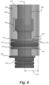
- Figure 6 depicts a first wire 208 connected to a first temperature sensor (not visible in Figure 6 ).
- the wire 208 connects the temperature sensor to other components within the device, such as the PCB 122.
- a controller arranged on the PCB 122, for example, can determine the temperature of the susceptor 132 based on signals received from the temperature sensor(s).
- the device 100 can be configured to control the one or more induction coils 124, 126 based on the detected temperature. For example, an inductor coil may be turned off when the temperature of the susceptor 132 has reached a pre-determined threshold.
- the support 136 further comprises a second portion 216, which is spaced apart from the first portion 212 along the axis 204.
- the second portion may be omitted.
- the second portion 216 may be similar to the first portion 212.
- the first and second portions 212, 216 may have a similar cross-sectional shape and/or size, and/or a similar depth.
- the second portion 216 comprises a second channel 218, through which the wire 208 is routed.
- the support 136 is hollow. Debris and/or liquid from the heated aerosol generating material may pass from the susceptor 132 and into the hollow cavity of the support 136. As mentioned in relation to Figure 3 , the device 100 may comprise a second lid 140 which can be opened to allow a user to clean the susceptor 132 and/or the support 136.
- Figure 7 shows a perspective view of the support 136 in the vicinity of the channel 210.
- the channel 210 is formed through the first portion 212, and the wire 208 passes through the channel 210.
- the channel 210 has a depth 302a measured in a direction perpendicular to the axis 204.
- the channels also have a width 302b measured in a direction perpendicular to the depth 302a. In this example, the depth 302a is about 1.3mm and the width 302b is about 0.9mm.
- the wire 208 is also surrounded by the resilient member 214, and passes through a second channel 218 formed in the second portion 216.
- the first portion 212 and the second portion 216 each comprise four channels, through which four wires 208, 308a, 308b, 308c are routed.
- the first wire 208 and the second wire 308a may be connected to a first temperature sensor
- the third wire 308b and the fourth wire 308c may be connected to a second temperature sensor, for example.
- Figure 8 shows diagrammatic representation of the support 136 of Figures 6 and 7 in a top-down view.
- the hollow, cylindrical susceptor 132 is shown engaged with the engagement region 202 of the support 136.
- the outer perimeter of the resilient member 214 extends further away from the axis 204 than the outer perimeter of the first portion 212, measured in a radial direction 304.
- the resilient member 214 can therefore abut the inner surface of the insulating member, when present.
- the device 100 comprises a hollow insulating member 128 which surrounds the susceptor 132.
- a space 406 (such as an air gap) is provided between the outer surface of the susceptor 132 and the inner surface of the insulating member 128.
- the device 100 comprises temperature sensor 424 which is affixed to an outer surface of the susceptor 132.
- a wire 408 is connected to the temperature sensor 424.
- One or more other wires may also be connected to the temperature sensor 424.
- the support 436 further comprises an end portion 420 which abuts the distal end of the insulating member 128.
- the end portion 420 supports and holds the insulating member 128 in place, while also helping further seal the space 406 between the susceptor 132 and the insulating member 128.
- the end portion 420 also defines a channel 426, in the form of a through hole, through which the wire 408 is routed. This allows the wire 408 to be connected to other components of the device 100.
- the first portion, the second portion, the susceptor and the insulating member each have a substantially circular shape cross section.
- the cross sections of any or all of these components may take any other shape, such as square, rectangular or elliptical.
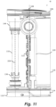
- Figure 11 depicts part of the device 100.
- the inductor coils 124, 126 and insulating member 128 have been omitted for clarity.
- the first support 136 defines an axis 204 which is arranged parallel to the longitudinal axis 158 of the susceptor 132, and it may also be arranged parallel to the longitudinal axis 134 of the device 100.
- the axis 204 may be the longitudinal axis of the support 136, for example.
- the first engagement region 202 may comprise two or more protrusions 224 or prongs which extend from an end of the first support 136 along the susceptor 132 in the direction of the axis 204.
- Each of the protrusions 224 are spaced around the outer surface of the susceptor 132 and are separated by a gap. These protrusions 224 flex outwards as the susceptor 132 is inserted into the first engagement region 202.
- the second support 144 comprises a second engagement region 506 at one end, which receives and engages a proximal end of the susceptor 132.
- the proximal end of the susceptor 132 is the end of the susceptor 132 that is arranged closest to a user's mouth when the device 100 is in use.
- the susceptor 132 and second engagement region 506 form an interference fit or friction fit, however other attachment means may be used.
- the second engagement region 506 may also comprise two or more protrusions 226 or prongs which extend from an end of the second support 144 along the susceptor 132 in the direction of the axis 204. Each of the protrusions 226 are spaced around the outer surface of the susceptor 132 and are separated by a gap. The protrusions 226 allow the second support 144 to flex as the susceptor 132 is inserted into the engagement region 506.
- the first and second supports 134, 144 may be made from the same, or different material.
- the first and second supports 134, 144 are both made from a plastics material, such as PEEK which a thermal conductivity of about 0.32W/mK and a melting point of about 343°C. With a low thermal conductivity, the rate at which heat flows from the susceptor 132 through the first and second supports 134, 144 is reduced. Other materials with low thermal conductivities may be used instead.
- the first and second supports 134, 144 are made from plastics materials because these can be lightweight.
- the susceptor 132 is heated by the first and second inductor coils 124, 126 to a temperature of between about 240°C and about 280°C.
- the first and second supports 134, 144 having a melting point which is greater than the temperature of the heated susceptor 132 by at least 60°C, the first and second supports 134, 144 are less likely to soften and weaken due to the heat.
- Figure 13 shows the arrangement of Figure 12 with an insulating member 128 surrounding the susceptor 132.
- the insulating member 128 is depicted as being transparent so that the susceptor 132 is visible within the hollow insulating member 128.
- the insulating member 128 may or may not be transparent.
- the insulating member 128 is positioned away from the susceptor 132 to provide an air gap 206 between the outer surface of the susceptor 132 and the inner surface of the insulating member 128.
- the air gap 206 provides insulation.
- the insulating member 128 may be held in place by one or more components of the device 100. In the present example, however, the insulating member 128 abuts the first support 136 towards one end of the insulating member.
- the first support 136 may comprise an end portion 220 which has a cross section that is larger than a cross section of the insulating member 128. A first end of the insulating member 128 therefore abuts the end portion 220 of the first support 136.
- the insulating member 128 can be held substantially parallel to the axis 204.
- the insulating member 128 also abuts the second support 144 towards an end of the insulating member 128.
- the second support 144 may also comprise an end portion 512 which has a cross section that is larger than a cross section of the insulating member 128. A second end of the insulating member 128 may therefore abut the end portion 512 of the second support 144.
- Figure 13 shows a small gap between the end portion 512 of the second support 144 and the second end of the insulating member 128. The small gap can allow for manufacturing tolerances and may not be present in certain examples.
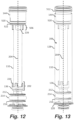
- Figures 12 and 13 show the first support 136 with a first resilient member 214 extending around a portion of the support 136.
- the first resilient member 214 is an O-ring.
- Figure 13 shows that the first resilient member 214 is dimensioned such that it abuts an inner surface of the insulating member 128 when the insulating member 128 is in place.
- the first resilient member 214 can therefore help seal the space 208 between the susceptor 132 and insulating member 128 to better insulate the device 100.
- the first resilient member 214 may be compressed when the insulating member 128 surrounds the susceptor 132.
- the first support 132 comprises a first portion 212 and a second portion 216, where the first resilient member 214 is arranged between the first and second portions 212, 216.
- the first and second portions 212, 216 stop the first resilient member 214 from sliding along the first support 136, which could reduce the sealing effect.
- the second support 144 comprises a recess 522 within which the second resilient member is located.
- the second resilient member 520 has a width that is smaller than a width of the first resilient member 214. The widths of the resilient members are measured in a direction perpendicular to the axis 204.
- the first and second resilient members 214, 520 are made from a material which has a thermal conductivity of less than about 0.5W/mK, such as less than about 0.25W/mK.
- the first and second resilient members 214, 520 may be made from silicone rubber, for example.
Landscapes
- Physics & Mathematics (AREA)
- Electromagnetism (AREA)
- Resistance Heating (AREA)
Abstract
Description
- The present invention relates to a support for a heater component of an aerosol provision device and an aerosol provision device including the support. The present invention also relates to an aerosol provision device, an aerosol provision system and an article comprising aerosol generating material.
- Smoking articles such as cigarettes, cigars and the like burn tobacco during use to create tobacco smoke. Attempts have been made to provide alternatives to these articles that burn tobacco by creating products that release compounds without burning. Examples of such products are heating devices which release compounds by heating, but not burning, the material. The material may be for example tobacco or other non-tobacco products, which may or may not contain nicotine.
- According to a first aspect of the present disclosure, there is provided a support for a heater component of an aerosol provision device, wherein the support defines an axis and is configured to engage an end of the heater component to hold the heater component substantially parallel to the axis at a predetermined distance from a coil, and wherein the support defines a channel to receive a wire of a temperature sensor, the channel defining an opening into a space between the heater component and the coil.
- According to a second aspect of the present disclosure, there is provided an aerosol provision device, comprising:
- a support according to the first aspect;
- a heater component engaged with the support at one end;
- a coil extending around the heater component, wherein the coil is configured to heat the heater component;
- a temperature sensor for sensing the temperature of the heater component, wherein the temperature sensor is positioned in a space between the coil and the heater component; and
- a wire positioned in the channel of the support and connected to the temperature sensor.
- According to a third aspect of the present disclosure, there is provided an aerosol provision device, comprising:
- a support defining an axis;
- a coil;
- a heater component, wherein:
- the heater component is heatable by the coil;
- an end of the heater component is engaged with the support to hold the heater component substantially parallel to the axis at a predetermined distance from the coil; and
- the support defines a channel which defines an opening into a space between the heater component and the coil;
- a temperature sensor for sensing the temperature of the heater component, wherein the temperature sensor is positioned in the space between the heater component and the coil; and
- a wire positioned in the channel of the support and connected to the temperature sensor.
- According to a fourth aspect of the present disclosure, there is provided an aerosol provision device, comprising:
- a heater component configured to heat aerosol generating material;
- a first support, wherein the first support defines an axis and is configured to engage a first end of the heater component;
- a second support, wherein the second support is configured to engage a second end of the heater component; and
- at least one coil configured to heat the heater component,
- wherein the first and second supports hold the heater component substantially parallel to the axis at a predetermined distance from the at least one coil.
- According to a fifth aspect of the present disclosure, there is provided an aerosol provision device, comprising:
- a heater component configured to heat aerosol generating material;
- a support, wherein the support defines an axis and is configured to engage a first end of the heater component; and
- at least one coil configured to heat the heater component,
- wherein the support holds the heater component substantially parallel to the axis at a predetermined distance from the at least one coil.
- Further features and advantages of the invention will become apparent from the following description of preferred embodiments of the invention, given by way of example only, which is made with reference to the accompanying drawings.
-
-
Figure 1 shows a front view of an example of an aerosol provision device; -
Figure 2 shows a front view of the aerosol provision device ofFigure 1 with an outer cover removed; -
Figure 3 shows a cross-sectional view of the aerosol provision device ofFigure 1 ; -
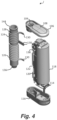
Figure 4 shows an exploded view of the aerosol provision device ofFigure 2 ; -
Figure 5A shows a cross-sectional view of a heating assembly within an aerosol provision device; -
Figure 5B shows a close-up view of a portion of the heating assembly ofFigure 5A ; -
Figure 6 shows a close-up view of the support in the aerosol provision device ofFigure 3 ; -
Figure 7 shows a close-up perspective view of channels formed in the support ofFigure 6 ; -
Figure 8 shows a diagrammatic representation of the support ofFigures 6 and7 in a top-down view; -
Figure 9 shows a diagrammatic representation of another example support; -
Figure 10 shows a diagrammatic representation of a further support; -
Figure 11 shows a susceptor arranged within an aerosol provision device; -
Figure 12 shows the susceptor engaged by first and second supports; and -
Figure 13 shows the susceptor surrounded by an insulating member. - As used herein, the term "aerosol generating material" includes materials that provide volatilised components upon heating, typically in the form of an aerosol. Aerosol generating material includes any tobacco-containing material and may, for example, include one or more of tobacco, tobacco derivatives, expanded tobacco, reconstituted tobacco or tobacco substitutes. Aerosol generating material also may include other, non-tobacco, products, which, depending on the product, may or may not contain nicotine. Aerosol generating material may for example be in the form of a solid, a liquid, a gel, a wax or the like. Aerosol generating material may for example also be a combination or a blend of materials. Aerosol generating material may also be known as "smokable material".
- Apparatus is known that heats aerosol generating material to volatilise at least one component of the aerosol generating material, typically to form an aerosol which can be inhaled, without burning or combusting the aerosol generating material. Such apparatus is sometimes described as an "aerosol generating device", an "aerosol provision device", a "heat-not-burn device", a "tobacco heating product device" or a "tobacco heating device" or similar. Similarly, there are also so-called e-cigarette devices, which typically vaporise an aerosol generating material in the form of a liquid, which may or may not contain nicotine. The aerosol generating material may be in the form of or be provided as part of a rod, cartridge or cassette or the like which can be inserted into the apparatus. A heater for heating and volatilising the aerosol generating material may be provided as a "permanent" part of the apparatus.
- An aerosol provision device can receive an article comprising aerosol generating material for heating. An "article" in this context is a component that includes or contains in use the aerosol generating material, which is heated to volatilise the aerosol generating material, and optionally other components in use. A user may insert the article into the aerosol provision device before it is heated to produce an aerosol, which the user subsequently inhales. The article may be, for example, of a predetermined or specific size that is configured to be placed within a heating chamber of the device which is sized to receive the article.
- A first aspect of the present disclosure defines a support for a heater component (such as a susceptor) of an aerosol provision device. As will be discussed in more detail herein, a susceptor is an electrically conducting object, which is heated via electromagnetic induction. An article comprising aerosol generating material can be received within the heater component. Once heated, the heater component transfers heat to the aerosol generating material, which releases the aerosol. In some cases, the device can monitor the temperature of the heater component in one or more locations, as it is being heated. This may be useful because the aerosol generating material may need to be heated to a specific temperature. For example, if the temperature of the heater component is too high, the aerosol generating material may overheat, which can impact the taste/flavour of the aerosol. If the temperature of the heater component is too low, the volume of aerosol generated may be too low. Accordingly, it may be useful to control and monitor the temperature of the heater component during heating.
- To monitor the temperature of the heater component, one or more temperature sensors may be in contact with, or positioned near, the heater component. The temperature sensor may be a thermocouple, for example. One or more wires may connect the temperature sensor to other electronic circuitry within the aerosol provision device, and the wires must therefore be routed from the heater component, to another location within the device.
- As mentioned, the heater component may be a susceptor, and the heater component may be heated by a coil (such as an inductor coil). An inductor coil is configured to generate a varying magnetic field. A susceptor is heatable by penetration with the varying magnetic field.
- In an example aerosol provision device, the heater component may be surrounded by one or more components, such as an insulating member which can be arranged coaxially with the heater component. The insulating member can help insulate other components of the device from the heat generated by the heater component. The insulating member may also support one or more coils which are positioned around, and spaced apart from, the heater component.
- In some conventional aerosol provision devices, the wires from the temperature sensors are routed through a surface of the insulating member. For example, one or more through holes may be formed through the insulating member, and the wires passed through the through hole. However, it has been found that the through hole can weaken the structural integrity of the insulating member. Thus, the insulating member is more prone to damage. In addition, depending upon the size and location of the through hole, the hole can also reduce the insulative effect provided by the insulating member. Thus, heat can escape from the space between the heater component and the insulating member.
- The present invention relates to a support which defines a channel through which the wire of a temperature sensor can pass. The support is an element which holds the heater component in place within the device. The channel formed in the support defines an opening into a space between the heater component and coil/insulating member. This means that the wire does not need to be routed through the insulating member so that its structural integrity is not compromised. One or more wires may be routed through the channel.
- The support, also known as a "cleanout tube", defines an axis and is configured to engage an end of the heater component to hold the heater component substantially parallel to the axis at a predetermined distance from a coil. The support therefore holds the heater component in place within the device, relative to the coil. The wire can therefore be routed along the heater component (generally in the direction of the axis), and through the channel so that it can extend out of the space between the heater component and the coil.
- The channel may extend substantially parallel to the axis. In other words, the channel is formed through a portion of the support in a direction that is substantially parallel to the axis. The wire, once received in the channel, therefore extends in a direction substantially parallel to the axis. This construction can be easier to manufacture, and also minimises length of wire used because it defines the shortest route into the space between the heater component and the coil/insulating member. In other examples the channel may not be parallel to the axis.
- The channel may be open along its length. In other words, the channel may be open around its perimeter. In contrast, a channel that is closed around its perimeter would be a through hole formed through a portion of the support. A channel which is open along its length can be easily manufactured and may allow the device to be assembled quicker. For example, the wire can be slotted into the channel, rather than requiring the wire to be threaded through a hole.
- The channel can have a depth which is measured in a direction perpendicular to the axis. The channel may therefore define a notch formed in a portion of the support. The channel may have a depth of less than about 5mm, or less than about 3mm. Preferably, the channel has a depth of less than about 2mm, such as about 1.7mm. If the channel is too deep, then heat may more easily escape from the space between the heater component and coil. If the channel is too shallow, then the wire may need to be angled with respect to the axis and heater component, which may bend or break the wire. The above dimensions provide a good balance between these considerations.
- The channel can have a width which is measured in a direction perpendicular to the axis and the depth. The channel may have a width of less than about 2mm, or less than about 1mm. Preferably, the channel has a width of about 0.9mm. If the channel is too wide, then heat may more easily escape from the space between the heater component and coil.
- The support may comprise a first portion, and the channel may be formed through the first portion. The first portion may have a first cross section, and may be arranged generally perpendicular to the axis. The first portion may be substantially circular in cross section, although other cross-sectional shapes are possible. The first portion may have a perimeter which extends around the axis. The first portion may have a first depth, measured in a direction parallel to the axis. The channel therefore has a length equal to the first depth if the channel is formed parallel to the axis, or has a length greater than the first depth if the channel is not parallel to the axis.
- In some examples, the channel is a notch at an outer perimeter of the first portion. In other examples however, the channel is closed around its perimeter such that a through hole is formed through the first portion. The inner diameter of the though hole can be substantially the same as the outer diameter of the wire, which thereby reduces heat loss from the heater component.
- The insulating member may surround the heater component and abut at least part of the first portion of the support, such that the insulating member is positioned at a predetermined radial distance outward/away from the heater component. The first portion may therefore be arranged inside the insulating member. The first portion can therefore act as "plug" to at least partially seal/enclose the space between the insulating member and the heater component. The first portion can therefore reduce heat loss.
- The support may comprise a second portion spaced apart from the first portion in a direction parallel to the axis, and a second channel may be formed through the second portion to receive the wire. The "channel" formed in the first portion may therefore be known as a "first channel". The second portion may have substantially the same shape and/or dimensions as the first portion. The wire therefore passes through the first channel formed in the first portion, and passes through the second channel formed in the second portion. The second portion provides a second "barrier" to help enclose/seal/insulate the space between the heater component and the induction coil/insulating member.
- In some examples the second portion may not comprise a channel. Instead, the wire may be routed around the second portion.
- The support (or aerosol provision device) may further comprise a resilient member arranged between the first and second portions. The resilient member can therefore be retained in position along the axis by the first and second portions. In other words, the resilient member cannot move along the axis beyond the first and second portions. The resilient member may be an O-ring, for example. The resilient member therefore surrounds the support and helps enclose/seal/insulate the space between the heater component and induction coil/insulating member. In examples where the insulating member is present, the resilient member may abut the inner surface of the insulating member.
- In some examples, the resilient member encloses/encircles the wire. In other words, the resilient member extends around the wire. Thus, in examples where the resilient member is an O-ring, the wire passes inside the "O". This arrangement can help keep the wires taught so that they are less likely to be damaged, and/or can hold the wires in the channel. Holding the wires in the channel can help stop the temperature sensor from being pulled away from the surface of the heater component.
- In another example, the wire passes through an aperture/hole formed in the resilient member. This arrangement means that the resilient member (such as an O-ring) can function better to create a seal. For example, the inner surface of the O-ring can better conform to the support without the wire running between the O-ring and support. The resilient member may be an O-ring, and the wire extends through an aperture formed in the O-ring such that the (total) outer circumference of wire abuts the O-ring.
- In some examples, the second portion may be omitted. In such an example, the resilient member be longitudinally spaced from the channel. In other words, the second portion is not necessarily needed to hold the resilient member in place. The O-ring may be held in place by friction; for example, the O-ring may grip the support as it encircles the support.
- The support may comprise an end portion, where the end portion is configured to abut an end of an insulating member which surrounds the heater component. The end portion therefore holds the insulating member in place, and may help enclose/seal the space between the heater component and induction coil/insulating member.
- The support may comprise at least two channels (each formed in the first portion). Each channel may receive a single wire. In other examples, two or more wires may be introduced into the, or each, channel. In a specific example there are four channels, each channel configured to receive a single wire. In one example, the device comprises two temperature sensors, each temperature sensor comprising two wires, and each wire is received in a separate channel.
- Having a separate channel for each wire helps electrically insulate each wire from adjacent wires. A separate channel for each wire can also reduce heat loss from the heater component.
- As mentioned, the second aspect of the present disclosure defines an aerosol provision device comprising a support as described above. The device further comprises a heater component engaged with the support at one end, and a coil extending around the heater component, where the coil is configured to heat the heater component (via a magnetic field, for example). The device further comprises a temperature sensor for sensing the temperature of the heater component, where the temperature sensor is positioned in a space between the coil and the heater component. The device further comprises a wire positioned in the channel of the support and connected to the temperature sensor.
- The device may define a longitudinal axis that is substantially parallel to the axis of the support. The device may define a proximal end, and a distal end. In use, the proximal end of the device may be held closer to a user's mouth than the distal end. In use, aerosol may be drawn towards the proximal end of the device. In an example, the support engages the distal end of the heater component.
- The device may further comprise an insulating member. The support may comprise a first portion, where the channel is formed through the first portion. The insulating member may surround the heater component and abut at least part of the first portion of the support, thereby to position the insulating member at a predetermined radial distance outward from the heater component. Thus, the insulating member surrounds the first portion of the support. In other words, the insulating member is arranged between the heater component and the coil, and is spaced apart from the axis by a first distance. A perimeter of the first portion is spaced apart from the axis by a second distance. The first distance may be substantially equal to the second distance. Thus, the first distance may be slightly greater than the second distance, so that the first portion may fit inside the hollow insulating member. The perimeter of the first portion may abut the inner surface of the insulating member. In examples where a resilient member is present, the outer edge of the resilient member may be spaced apart from the axis by a third distance, the third distance being substantially equal to the first distance. Thus, the resilient member may abut the inner surface of the insulating member.
- In some examples, the device comprises a first coil and a second coil. The first coil may be used to heat a first portion of the heater component, and the second coil may be used to heat a second portion of the heater component. In an example, the device comprises a first temperature sensor arranged to sense a temperature of the first portion of the heater component, and a second temperature sensor arranged to sense a temperature of the second portion of the heater component. Each temperature sensor may be associated with two wires, and the support may define four channels, where each channel receives a wire.
- Accordingly, the device may comprise a second temperature sensor for sensing the temperature of the heater component, wherein the second temperature sensor is positioned in the space between the coil and the heater component and a second wire is connected to the second temperature sensor, wherein the support defines a second channel to receive the second wire.
- In some examples the temperature sensor is in contact with the heater component. This allows for a more accurate reading of the heater component temperature.
- A fourth aspect of the present disclosure relates to the positioning of a heater component in relation to first and second supports. The first and second supports engage opposite ends of the heater component and hold the heater component in place within the aerosol provision device. One or more coils are positioned away from the heater component by a predetermined distance. In some arrangements, the one or more coils extend around the heater component. The heater component may be known as a susceptor, in some examples.
- The first and second supports (also known as heater component mounts, or susceptor mounts) ensure that the heater component is adequately positioned in relation to the one or more coils. By keeping the distance between the heater component and coil constant over time, the heater component can be heated effectively each time the device is used. Furthermore, because the first and second supports are not integral with the heater component, heat is transferred to the first and second supports at a slower rate. This can help insulate other components of the device from the heated heater component. In other examples, however, the first and second supports are integral with the heater component. For example, they may be moulded together. While this may increase the rate at which heat conducts away from the heater component, it can more robustly hold the heater component in place.
- The first and second supports may be thermally insulating. As mentioned above, this reduces the rate of heat flow through the first and second supports, to other components of the device. In one particular example, the first and second supports have thermal conductivity of less than about 0.5W/mK. It has been found that when the first and second supports have thermal conductivities below this value, an adequate insulating effect can be achieved. The first and second supports may have the same, or different thermal conductivities. In a further example, the first and second supports have a thermal conductivity of less than about 0.35W/mK, such as about 0.32W/mK.
- The first and second supports may comprise a plastics material. For example, they may be entirely, or partially made from one or more plastics materials. Preferably the portion of the support which engages the heater component comprises the plastics material. Plastics are good thermal insulators, are relatively inexpensive, are lightweight, and can easily be moulded into the required shape to engage the heater component. In one example the plastics material comprises polyether ether ketone (PEEK). PEEK is a particularly suitable material for the first and second supports because it has a thermal conductivity of about 0.32W/mK, a melting point of about 343°C and is not electrically conductive, so will not generate heat as a result of the coils. In one example, the PEEK is Victrex® PEEK 450G.
- In some examples, the first and second supports have a melting point of greater than about 300°C. Preferably, the first and second supports have a melting point of greater than about 340°C. In some examples, in use, the one or more coils are configured to heat the heater component to a temperature of between about 240°C and about 280°C. Thus, by having first and second supports with a melting point temperature that is above the temperature of the heated heater component, the first and second supports are less likely to soften and lose their structural integrity due to melting.
- In use, the at least one coil may be configured to heat the heater component to a first temperature and the first and second supports have a melting point of a second temperature, wherein the second temperature is greater than the first temperature by at least about 60 °C. This ensures that the first and second supports remain structurally stable, and do not begin to weaken as the temperature of heater component increases. For example, in some arrangements, the first temperature is 250°C and the second temperature is 343°C. In another example, the first temperature is 280°C and the second temperature is 343°C. In some devices the coils may operate in two modes. In a first mode the heater is heated to a lower temperature than in a second mode.
- In some examples, the aerosol provision device further comprises an insulating member extending around the heater component, wherein the insulating member is positioned away from the heater component to provide an air gap around the heater component. The insulating member may be positioned between the at least one coil and the heater component such that the at least one coil extends around the insulating member. In certain arrangements the coil may be in contact with the insulating member. However, in other examples a further air gap may be provided between the insulating member and the coil. Such an arrangement provides a device with improved insulation. The specific order of the air gap and the insulating member provides improved insulation from the heated heater component. The air gap helps insulate the insulating member from the heat. In addition, the first and second supports, the air gap and the insulating member help insulate other components of the device from the heat. For example, the supports, air gap and insulating member reduce any heating of the coil, electronics, and/or battery by the heater component.
- As mentioned above, the insulating member is positioned away from the receptacle/heater component to provide an air gap. For example, the inner surface of the insulating member is spaced apart from the outer surface of the heater component. This means that an air gap surrounds the outer surface of the heater component, and the heater component is not in contact with the insulating member in this region. Any contact could provide a thermal bridge along which heat could flow.
- In a particular arrangement the heater component is elongate and defines an axis, such as a longitudinal axis. The insulating member extends around the heater component and the axis in an azimuthal direction. The insulating member is therefore positioned radially outward from the heater component, for example the insulating member may be coaxial with the heater component. This radial direction is defined as being perpendicular to the axis of the heater component. Similarly, the coil extends around the insulating member and is positioned radially outwards from both the heater component and the insulating member. The coil may be coaxial with the insulating member and the heater component.
- The insulating member is thermally insulating. For example, it may comprise a plastics material and may have low thermal conductivity such as a thermal conductivity of less than about 0.5W/mK. In one example the plastics material is PEEK, and may therefore be made from the same material as the first and second supports.
- The insulating member may abut at least one of the first support and the second support such that the insulating member is held substantially parallel to the axis. For example, the insulating member may extend between the first and second supports such that a first end of the insulating member abuts the first support and a second end of the insulating member abuts the second support. The first and second supports may therefore also support the insulating member as well as the heater component, which reduces the number of components in the device.
- The first support may comprise a first resilient member and the resilient member may abut an inner surface of the insulating member. The insulating member may therefore extend around a portion of the first support which comprises the first resilient member. The resilient member may be an O-ring, for example. The resilient member may extend around an outer surface of the first support. When the resilient member abuts the inner surface of the insulating member it can help seal the space between the heater component and insulating member to better insulate the heater component from other components of the device. In some examples the resilient member may not abut the inner surface of the insulating member, but may nevertheless provide improved insulation when compared to an arrangement without a resilient member.
- The first support may comprise a first portion and a second portion spaced apart from the first portion in a direction parallel to the axis, and wherein the resilient member is arranged between the first and second portions. The resilient member can therefore be retained in position along the axis by the first and second portions. In other words, the resilient member cannot move along the axis beyond the first and second portions.
- The second support may comprise a second resilient member and the second resilient member may abut the inner surface of the insulating member, such that the first and second resilient members seal the air gap. The insulating member may therefore extend around a portion of the second support which comprises the second resilient member. The second resilient member may be an O-ring, for example. The second resilient member may extend around an outer surface of the second support. When the second resilient member abuts the inner surface of the insulating member it can help seal the space between the heater component and insulating member to better insulate the heater component from other components of the device. In some examples the second resilient member may not abut the inner surface of the insulating member, but may nevertheless provide improved insulation when compared to an arrangement without a second resilient member.
- In some examples, the second support comprises a recess within which the second resilient member is received/located. By having a recess, rather than first and second portions like the first support, the main body of the second support can be made wider, thereby allowing the second support to function as an expansion chamber. A wider expansion chamber allows the hot aerosol to expand in volume, and thereby cool to a more comfortable temperature. For at least the same purpose, in some examples the second resilient member may have a width that is smaller than a width of the first resilient member.
- Alternatively, the second support may comprise a third portion and a fourth portion spaced apart from the third portion in a direction parallel to the axis, and wherein the second resilient member is arranged between the third and fourth portions.
- The resilient members may comprise silicone, such as silicone rubber. Silicone rubber is heat resistant and has good mechanical properties which remain unchanged in a wide range of temperatures. Silicone rubber is also safe for use in aerosol provision devices. In one example, the silicone rubber is Elastosil™ from Wacker Chemie AG.
- The resilient members may be thermally insulating. For example, they may have a thermal conductivity of less than about 0.5W/mK. This slows the transfer of heat between the supports and other components of the device.
- The first and second resilient members may have a first thermal conductivity and the first and second supports may have a second thermal conductivity, and wherein the first thermal conductivity is less than the second thermal conductivity. Thus, each of the first and second resilient members may have a thermal conductivity that is less than the thermal conductivities of the first and second supports. This specific arrangement reduces the rate at which heat flows from the heater component, through the first and second supports, and through the first and second resilient members to the insulating member. This helps insulate the insulating member. In a particular example the first thermal conductivity is less than about 0.3W/mK and the second thermal conductivity is less than about 0.5W/mK. For example, silicone rubber can have a thermal conductivity of between about 0.2W/mK and about 0.25W/mK and PEEK can have a thermal conductivity of about 0.32W/mK. Although the first and second resilient members may have a thermal conductivity that is less than the thermal conductivity of the first and second supports, they may each have different thermal conductivities. Similarly, the first and second supports may each have different thermal conductivities.
- It is desirable to reduce the surface area of the insulating member that is in contact with the first and second resilient members to reduce/slow the flow of heat. Similarly, it is desirable to reduce the surface area of the heater component that is in contact with the first and second supports to reduce/slow the flow of heat. In one example, less than 5% of the surface area of the heater component is in contact with each support. Preferably, less than 3% of the surface area of the heater component is in contact with each support. More preferably, less than 2% of the surface area of the heater component is in contact with each support. In some examples, more than 1% of the surface area of the heater component is in contact with each support. This can provide sufficient engagement to hold the heater component in place.
- In some examples, instead of having either or both of the resilient members, the insulating member can be moulded to the first and/or second supports to help seal the space between the heater component and the insulating member. While this may increase the flow of heat, it can provide a better seal.
- The first support may comprise an engagement region comprising two or more protrusions which extend along the heater component in a direction parallel to the axis. Each of the protrusions may be spaced apart around the outer surface of the heater component and be separated by a gap. The protrusions allow the first support to flex outwards as the heater component is inserted into, and engages with, the engagement region. This makes it easier for the device to be assembled, and reduces the likelihood of damaging the heater component.
- The second support may also comprise a second engagement region comprising two or more protrusions which extend along the heater component in a direction parallel to the axis.
- Preferably the engagement region(s) comprise three or four protrusions to provide greater support.
- In some examples, the heater component comprises an inductively heatable portion and a non-inductively heated portion. The inductively heatable portion heats the article. One or more non-inductively heated portions can connect the heater component to the device, and so preferably are good heat insulators. The non-inductively heated portion can also provide rigidity for receiving an article. The one or more non-inductively heated portions may be arranged at ends of the heater component.
- In a specific example, the heater component comprises an inductively heatable portion and a first non-inductively heated portion arranged at a first end of the heater component, and a second non-inductively heated portion arranged at a second end of the heater component. The first support can engage the first non-inductively heated portion and the second support can engage the second non-inductively heated portion. By engaging non-inductively heated portions, the heater component can be better supported and the first and second supports can be better insulated from the inductively heatable portion.
- In another aspect, there is provided a first support for supporting a heater component of an aerosol provision device, wherein the first support defines an axis and is configured to engage a first end of the heater component to hold the heater component substantially parallel to the axis at a predetermined distance from at least one coil. The first support may have any or all of the features described above in relation to the aerosol provision device.
- In another aspect, there is provided a second support for supporting a heater component of an aerosol provision device, wherein the second support is configured to engage a second end of the heater component to hold the heater component substantially parallel to an axis at a predetermined distance from at least one coil. The second support may have any or all of the features described above in relation to the aerosol provision device.
- In some examples, the device may only comprise one of the first and second supports. For example, in one aspect, there is provided an aerosol provision device, comprising a heater component configured to heat aerosol generating material, a support, wherein the support defines an axis and is configured to engage a first end of the heater component, and at least one coil configured to heat the heater component. The support holds the heater component substantially parallel to the axis at a predetermined distance from the at least one coil. In such an example, less than 5% of the surface area of the heater component may be in contact with the support. Preferably, less than 3% of the surface area of the heater component is in contact with the support. More preferably, less than 2% of the surface area of the heater component is in contact with the support. In some examples, more than 1% of the surface area of the heater component is in contact with the support. This can provide sufficient engagement to hold the heater component in place.
- The heater component may be hollow and/or substantially tubular to allow the aerosol generating material to be received within the heater component, such that the heater component surrounds the aerosol generating material. The insulating member may be hollow and/or substantially tubular so that the heater component can be positioned within the insulating member.
- The coil may be substantially helical. For example, the coil may be formed from wire, such as Litz wire, which is wound helically around the insulating member. In another example, the coil may not extend around the heater component, but instead may be arranged differently but nevertheless heat the heater component.
- The coil may be positioned away from an outer surface of the heater component by a distance of between about 3mm and about 4mm. Accordingly, the inner surface of the coil and the outer surface of the heater component may be spaced apart by this distance. The distance may be a radial distance. It has been found that distances within this range represent a good balance between the heater component being radially close to the coil to allow efficient heating of the heater component and being radially distant for improved insulation of the coil (and insulating member, if present).
- In another example, the coil may be positioned away from the outer surface of the heater component by a distance of greater than about 2.5 mm.
- In another example, the coil may be positioned away from an outer surface of the heater component by a distance of between about 3mm and about 3.5mm. In a further example, the coil may be positioned away from an outer surface of the heater component by a distance of between about 3mm and about 3.25mm, for example preferably by about 3.25mm. In another example, the coil may be positioned away from an outer surface of the heater component by a distance greater than about 3.2mm. In a further example the coil may be positioned away from an outer surface of the heater component by a distance of less than about 3.5mm, or by less than about 3.3mm. It has been found that these distances provide a balance between the heater component being radially close to the coil to allow efficient heating and being radially distant for improved insulation of the coil and insulating member.
- Reference to an "outer surface" of an entity means the surface positioned furthest away from the axis of the heater component, in a direction perpendicular to the axis. Similarly, reference to an "inner surface" of an entity means the surface positioned closest to the axis of the heater component, in a direction perpendicular to the axis.
- The insulating member may have a thickness of between about 0.25mm and about 1mm. For example, the insulating member may have a thickness of less than about 0.7mm, or less than about 0.6mm, or may have a thickness of between about 0.25mm and about 0.75mm, or preferably has a thickness of between about 0.4mm and about 0.6mm, such as about 0.5mm. It has been found that these thicknesses represent a good balance between reducing heating of the insulating member and coil (by making the insulating member thinner to increase the air gap size), and increasing the robustness of the insulating member (by making it thicker).
- The heater component may have a thickness between about 0.025mm and about 0.5mm, or between about 0.025mm and about 0.25mm, or between about 0.03mm and about 0.1mm, or between about 0.04mm and about 0.06mm. For example, the heater component may have a thickness of greater than about 0.025mm, or greater than about 0.03mm, or greater than about 0.04mm, or less than about 0.5mm, or less than about 0.25mm, or less than about 0.1mm, or less than about 0.06mm. It has been found that these thicknesses provide a good balance between fast heating of the heater component (as it is made thinner), and ensuring that the heater component is robust (as it is made thicker).
- In an example, the heater component has a thickness of about 0.05mm. This provides a balance between fast and effective heating, and robustness. Such a heater component may be easier to manufacture and assemble as part of an aerosol provision device than other heater components with thinner dimensions.
- Reference to the "thickness" of an entity means the average distance between the inner surface of the entity and the outer surface of the entity. Thickness may be measured in a direction perpendicular to the axis of the heater component.
- In a particular arrangement of the aerosol provision device, the coil is positioned away from an outer surface of the heater component by a distance of between about 3mm and about 4mm, the insulating member has a thickness of between about 0.25mm and about 1mm, and the heater component has a thickness of between about 0.025mm and about 0.5mm. Such an aerosol provision device allows quick heating of the heater component and effective insulative properties.
- In another particular arrangement, the coil may be positioned away from an outer surface of the heater component by a distance of between about 3mm and about 3.5mm, the insulating member has a thickness of between about 0.25mm and about 0.75mm, and the heater component has a thickness of between about 0.04mm and about 0.06mm. Such an aerosol provision device allows improved heating of the heater component and improved insulative properties.
- In a further particular arrangement, the coil is positioned away from an outer surface of the heater component by a distance of about 3.25mm, the insulating member has a thickness of about 0.5mm, and the heater component has a thickness of about 0.05mm. Such an aerosol provision device allows efficient heating of the heater component and good insulative properties.
- The coil, the heater component and the insulating member may be coaxial. This arrangement ensures that the heater component is heated effectively, and ensures that the air gap and insulating member provide effective insulation.
- The inner surface of the coil may be in contact with an outer surface of the insulating member. Thus, the insulating member can support the coil without the need for other components. In other examples however there may be a further air gap present between the inner surface of the coil and the outer surface of the insulating member. The distance between the inner surface of the coil and the outer surface of the insulating member may be less than about 0. 1mm, for example it may be about 0.05mm.
- The insulating member may have a melting point of greater than about 280 °C, such as greater than about 300 °C, or greater than about 340 °C. PEEK has a melting point of 343 °C. Insulating members with such melting points ensure that the insulating member remains rigid/solid when the heater component is heated.
- Preferably, the device is a tobacco heating device, also known as a heat-not-burn device.
- As briefly mentioned above, in some examples, the coil(s) is/are configured to, in use, cause heating of at least one electrically-conductive heating component/element (also known as a heater component/element), so that heat energy is conductible from the at least one electrically-conductive heating component to aerosol generating material to thereby cause heating of the aerosol generating material.
- In some examples, the coil(s) is/are configured to generate, in use, a varying magnetic field for penetrating at least one heating component/element, to thereby cause induction heating and/or magnetic hysteresis heating of the at least one heating component. In such an arrangement, the or each heating component may be termed a "susceptor". A coil that is configured to generate, in use, a varying magnetic field for penetrating at least one electrically-conductive heating component, to thereby cause induction heating of the at least one electrically-conductive heating component, may be termed an "induction coil" or "inductor coil".
- The device may include the heating component(s), for example electrically-conductive heating component(s), and the heating component(s) may be suitably located or locatable relative to the coil(s) to enable such heating of the heating component(s). The heating component(s) may be in a fixed position relative to the coil(s). Alternatively, both the device and an article/consumable may comprise at least one respective heating component, for example at least one electrically-conductive heating component, and the coil(s) may be to cause heating of the heating component(s) of each of the device and the article when the article is in the heating zone.
- In some examples, the coil(s) is/are helical. In some examples, the coil(s) encircles at least a part of a heating zone of the device that is configured to receive aerosol generating material. In some examples, the coil(s) is/are helical coil(s) that encircles at least a part of the heating zone. The heating zone may be a receptacle, shaped to receive the aerosol generating material.
- In some examples, the device comprises an electrically-conductive heating component that at least partially surrounds the heating zone, and the coil(s) is/are helical coil(s) that encircles at least a part of the electrically-conductive heating component. In some examples, the electrically-conductive heating component is tubular. In some examples, the coil is an inductor coil.
-
Figure 1 shows an example of anaerosol provision device 100 for generating aerosol from an aerosol generating medium/material. In broad outline, thedevice 100 may be used to heat areplaceable article 110 comprising the aerosol generating medium, to generate an aerosol or other inhalable medium which is inhaled by a user of thedevice 100. - The
device 100 comprises a housing 102 (in the form of an outer cover) which surrounds and houses various components of thedevice 100. Thedevice 100 has anopening 104 in one end, through which thearticle 110 may be inserted for heating by a heating assembly. In use, thearticle 110 may be fully or partially inserted into the heating assembly where it may be heated by one or more components of the heater assembly. - The
device 100 of this example comprises afirst end member 106 which comprises alid 108 which is moveable relative to thefirst end member 106 to close theopening 104 when noarticle 110 is in place. InFigure 1 , thelid 108 is shown in an open configuration, however thecap 108 may move into a closed configuration. For example, a user may cause thelid 108 to slide in the direction of arrow "A". - The
device 100 may also include a user-operable control element 112, such as a button or switch, which operates thedevice 100 when pressed. For example, a user may turn on thedevice 100 by operating theswitch 112. - The
device 100 may also comprise an electrical component, such as a socket/port 114, which can receive a cable to charge a battery of thedevice 100. For example, thesocket 114 may be a charging port, such as a USB charging port. -
Figure 2 depicts thedevice 100 ofFigure 1 with theouter cover 102 removed and without anarticle 110 present. Thedevice 100 defines alongitudinal axis 134. - As shown in
Figure 2 , thefirst end member 106 is arranged at one end of thedevice 100 and asecond end member 116 is arranged at an opposite end of thedevice 100. The first andsecond end members device 100. For example, the bottom surface of thesecond end member 116 at least partially defines a bottom surface of thedevice 100. Edges of theouter cover 102 may also define a portion of the end surfaces. In this example, thelid 108 also defines a portion of a top surface of thedevice 100. - The end of the device closest to the
opening 104 may be known as the proximal end (or mouth end) of thedevice 100 because, in use, it is closest to the mouth of the user. In use, a user inserts anarticle 110 into theopening 104, operates theuser control 112 to begin heating the aerosol generating material and draws on the aerosol generated in the device. This causes the aerosol to flow through thedevice 100 along a flow path towards the proximal end of thedevice 100. - The other end of the device furthest away from the
opening 104 may be known as the distal end of thedevice 100 because, in use, it is the end furthest away from the mouth of the user. As a user draws on the aerosol generated in the device, the aerosol flows away from the distal end of thedevice 100. - The
device 100 further comprises apower source 118. Thepower source 118 may be, for example, a battery, such as a rechargeable battery or a non-rechargeable battery. Examples of suitable batteries include, for example, a lithium battery (such as a lithium-ion battery), a nickel battery (such as a nickel-cadmium battery), and an alkaline battery. The battery is electrically coupled to the heating assembly to supply electrical power when required and under control of a controller (not shown) to heat the aerosol generating material. In this example, the battery is connected to acentral support 120 which holds thebattery 118 in place. - The device further comprises at least one
electronics module 122. Theelectronics module 122 may comprise, for example, a printed circuit board (PCB). ThePCB 122 may support at least one controller, such as a processor, and memory. ThePCB 122 may also comprise one or more electrical tracks to electrically connect together various electronic components of thedevice 100. For example, the battery terminals may be electrically connected to thePCB 122 so that power can be distributed throughout thedevice 100. Thesocket 114 may also be electrically coupled to the battery via the electrical tracks. - In the
example device 100, the heating assembly is an inductive heating assembly and comprises various components to heat the aerosol generating material of thearticle 110 via an inductive heating process. Induction heating is a process of heating an electrically conducting object (such as a susceptor) by electromagnetic induction. An induction heating assembly may comprise an inductive element, for example, one or more inductor coils, and a device for passing a varying electric current, such as an alternating electric current, through the inductive element. The varying electric current in the inductive element produces a varying magnetic field. The varying magnetic field penetrates a susceptor suitably positioned with respect to the inductive element, and generates eddy currents inside the susceptor. The susceptor has electrical resistance to the eddy currents, and hence the flow of the eddy currents against this resistance causes the susceptor to be heated by Joule heating. In cases where the susceptor comprises ferromagnetic material such as iron, nickel or cobalt, heat may also be generated by magnetic hysteresis losses in the susceptor, i.e. by the varying orientation of magnetic dipoles in the magnetic material as a result of their alignment with the varying magnetic field. In inductive heating, as compared to heating by conduction for example, heat is generated inside the susceptor, allowing for rapid heating. Further, there need not be any physical contact between the inductive heater and the susceptor, allowing for enhanced freedom in construction and application. - The induction heating assembly of the
example device 100 comprises a susceptor arrangement 132 (herein referred to as "a susceptor"), afirst inductor coil 124 and asecond inductor coil 126. The first and second inductor coils 124, 126 are made from an electrically conducting material. In this example, the first and second inductor coils 124, 126 are made from Litz wire/cable which is wound in a helical fashion to provide helical inductor coils 124, 126. Litz wire comprises a plurality of individual wires which are individually insulated and are twisted together to form a single wire. Litz wires are designed to reduce the skin effect losses in a conductor. In theexample device 100, the first and second inductor coils 124, 126 are made from copper Litz wire which has a rectangular cross section. In other examples the Litz wire can have other shape cross sections, such as circular. - The
first inductor coil 124 is configured to generate a first varying magnetic field for heating a first section of thesusceptor 132 and thesecond inductor coil 126 is configured to generate a second varying magnetic field for heating a second section of thesusceptor 132. In this example, thefirst inductor coil 124 is adjacent to thesecond inductor coil 126 in a direction along thelongitudinal axis 134 of the device 100 (that is, the first and second inductor coils 124, 126 to not overlap). Thesusceptor arrangement 132 may comprise a single susceptor, or two or more separate susceptors.Ends 130 of the first and second inductor coils 124, 126 can be connected to thePCB 122. - It will be appreciated that the first and second inductor coils 124, 126, in some examples, may have at least one characteristic different from each other. For example, the
first inductor coil 124 may have at least one characteristic different from thesecond inductor coil 126. More specifically, in one example, thefirst inductor coil 124 may have a different value of inductance than thesecond inductor coil 126. InFigure 2 , the first and second inductor coils 124, 126 are of different lengths such that thefirst inductor coil 124 is wound over a smaller section of thesusceptor 132 than thesecond inductor coil 126. Thus, thefirst inductor coil 124 may comprise a different number of turns than the second inductor coil 126 (assuming that the spacing between individual turns is substantially the same). In yet another example, thefirst inductor coil 124 may be made from a different material to thesecond inductor coil 126. In some examples, the first and second inductor coils 124, 126 may be substantially identical. - In this example, the
first inductor coil 124 and thesecond inductor coil 126 are wound in opposite directions. This can be useful when the inductor coils are active at different times. For example, initially, thefirst inductor coil 124 may be operating to heat a first section of thearticle 110, and at a later time, thesecond inductor coil 126 may be operating to heat a second section of thearticle 110. Winding the coils in opposite directions helps reduce the current induced in the inactive coil when used in conjunction with a particular type of control circuit. InFigure 2 , thefirst inductor coil 124 is a right-hand helix and thesecond inductor coil 126 is a left-hand helix. However, in another embodiment, the inductor coils 124, 126 may be wound in the same direction, or thefirst inductor coil 124 may be a left-hand helix and thesecond inductor coil 126 may be a right-hand helix. - The
susceptor 132 of this example is hollow and therefore defines a receptacle within which aerosol generating material is received. For example, thearticle 110 can be inserted into thesusceptor 132. In this example thesusceptor 120 is tubular, with a circular cross section. - The
device 100 ofFigure 2 further comprises an insulatingmember 128 which may be generally tubular and at least partially surround thesusceptor 132. The insulatingmember 128 may be constructed from any insulating material, such as plastic for example. In this particular example, the insulating member is constructed from polyether ether ketone (PEEK). The insulatingmember 128 may help insulate the various components of thedevice 100 from the heat generated in thesusceptor 132. - The insulating
member 128 can also fully or partially support the first and second inductor coils 124, 126. For example, as shown inFigure 2 , the first and second inductor coils 124, 126 are positioned around the insulatingmember 128 and are in contact with a radially outward surface of the insulatingmember 128. In some examples the insulatingmember 128 does not abut the first and second inductor coils 124, 126. For example, a small gap may be present between the outer surface of the insulatingmember 128 and the inner surface of the first and second inductor coils 124, 126. - In a specific example, the
susceptor 132, the insulatingmember 128, and the first and second inductor coils 124, 126 are coaxial around a central longitudinal axis of thesusceptor 132. -
Figure 3 shows a side view ofdevice 100 in partial cross-section. Theouter cover 102 is present in this example. The rectangular cross-sectional shape of the first and second inductor coils 124, 126 is more clearly visible. - The
device 100 further comprises asupport 136 which engages one end of thesusceptor 132 to hold thesusceptor 132 in place. Thesupport 136 is connected to thesecond end member 116. - The device may also comprise a second printed
circuit board 138 associated within thecontrol element 112. - The
device 100 further comprises a second lid/cap 140 and aspring 142, arranged towards the distal end of thedevice 100. Thespring 142 allows thesecond lid 140 to be opened, to provide access to thesusceptor 132. A user may open thesecond lid 140 to clean thesusceptor 132 and/or thesupport 136. - The
device 100 further comprises anexpansion chamber 144 which extends away from a proximal end of thesusceptor 132 towards the opening 104 of the device. Located at least partially within theexpansion chamber 144 is aretention clip 146 to abut and hold thearticle 110 when received within thedevice 100. Theexpansion chamber 144 is connected to theend member 106. -
Figure 4 is an exploded view of thedevice 100 ofFigure 1 , with theouter cover 102 omitted. -
Figure 5A depicts a cross section of a portion of thedevice 100 ofFigure 1 .Figure 5B depicts a close-up of a region ofFigure 5A. Figures 5A and 5B show thearticle 110 received within thesusceptor 132, where thearticle 110 is dimensioned so that the outer surface of thearticle 110 abuts the inner surface of thesusceptor 132. This ensures that the heating is most efficient. Thearticle 110 of this example comprisesaerosol generating material 110a. Theaerosol generating material 110a is positioned within thesusceptor 132. Thearticle 110 may also comprise other components such as a filter, wrapping materials and/or a cooling structure. -
Figure 5B shows alongitudinal axis 158 of the hollow,tubular susceptor 132. The inner and outer surfaces of thesusceptor 132 extend around theaxis 158 in an azimuthal direction. Surrounding thesusceptor 132 may be the hollow, tubular insulatingmember 128. An inner surface of the insulatingmember 128 is positioned away from the outer surface of thesusceptor 132 to provide an air gap between the insulatingmember 128 and thesusceptor 132. The air gap provides insulation from the heat generated in thesusceptor 132. Surrounding the insulatingmember 128 are the inductor coils 124, 126. It will be appreciated that in some examples just one inductor coil may surround the insulatingmember 128. The inductor coils 124, 126 are helically wrapped around the insulating member, and extend along theaxis 158. -
Figure 5B shows that the outer surface of thesusceptor 132 is spaced apart from the inner surface of the inductor coils 124, 126 by adistance 150, measured in a direction perpendicular to thelongitudinal axis 158 of thesusceptor 132. In one particular example, thedistance 150 is about 3mm to 4mm, about 3-3.5mm, or about 3.25mm. The outer surface of thesusceptor 132 is the surface that is furthest away from theaxis 158. The inner surface of thesusceptor 132 is the surface that is closest to theaxis 158. The inner surface of the inductor coils 124, 126 is the surface that is closest to theaxis 158. The outer surface of the insulatingmember 128 is the surface that is furthest away from theaxis 158. - To achieve the
relative spacing 150 between the susceptor 132 and the inductor coils 124, 126, thesusceptor 132 can be held in place by one or more components of thedevice 100. In the example ofFigure 5A , thesusceptor 132 is held in place at one end by afirst support 136, and at the other end by a second support 144 (which may also function as an expansion chamber). The insulatingmember 128 may also be held in place by the first andsecond supports -
Figure 5B further shows that the outer surface of the insulatingmember 128 is spaced apart from the inner surface of the inductor coils 124, 126 by adistance 152, measured in a direction perpendicular to alongitudinal axis 158 of thesusceptor 132. In one particular example, thedistance 152 is about 0.05mm. In another example, thedistance 152 is substantially 0mm, such that the inductor coils 124, 126 abut and touch the insulatingmember 128. - In one example, the
susceptor 132 has awall thickness 154 of about 0.025mm to 1mm. In this example, thesusceptor 132 has athickness 154 of about 0.05mm. The thickness of thesusceptor 132 is the average distance between the inner surface of thesusceptor 132 and the outer surface of thesusceptor 132, measured in a direction perpendicular to theaxis 158. - In one example, the
susceptor 132 has a length of about 40mm to 60mm, about 40mm to 50mm, about 40mm to 45mm, or about 44.5mm. In this particular example, thesusceptor 132 has a length of about 44.5mm and can receive anarticle 110 comprising aerosol generating material, where theaerosol generating material 110a has a length of about 42mm. The length of the aerosol generating material andsusceptor 132 is measured in a direction parallel to theaxis 158. - In an example, the insulating
member 128 has athickness 156 of between about 0.25mm and about 2mm, or between about 0.25mm and about 1mm. In this particular example, the insulating member has athickness 156 of about 0.5mm. Thethickness 156 of the insulatingmember 128 is the average distance between the inner surface of the insulatingmember 128 and the outer surface of the insulatingmember 128, measured in a direction perpendicular to theaxis 158. -
Figure 6 depicts a close up of thesupport 136, which was briefly described above in relation toFigure 3 . Thesupport 136 defines anaxis 204 which is arranged parallel to thelongitudinal axis 134 of thedevice 100. Theaxis 204 may be the longitudinal axis of thesupport 136, for example. - The
support 136 comprises anengagement region 202 at one end, which receives and engages a distal end of thesusceptor 132. The distal end of thesusceptor 132 is the end of thesusceptor 132 that is arranged furthest away from a user's mouth when thedevice 100 is in use. In other examples, thesupport 136 may arranged to engage the other end of thesusceptor 132. In this example thesusceptor 132 andengagement region 202 form an interference fit, however other attachment means may be used. Thesupport 136 holds the susceptor parallel to theaxis 204 at a predetermined distance from the one or more inductor coils 124, 126 which surround the susceptor (most clearly seen inFigure 2 ). - As mentioned above, the
device 100 comprises a hollow insulatingmember 128 which surrounds thesusceptor 132 and at least a portion of thesupport 136. An inner surface of the insulatingmember 128 is arranged at a predetermined distance from theaxis 204. A space 206 (such as an air gap) is provided between the outer surface of thesusceptor 132 and the inner surface of the insulatingmember 128. Theair gap 206, and insulatingmember 128 act to insulate components of thedevice 100 from the heat generated in thesusceptor 132. - The
device 100 may comprise one or more temperature sensors, which can be used to measure the temperature of thesusceptor 132. A temperature sensor may be affixed to the outer surface of thesusceptor 132, or may be arranged in proximity to thesusceptor 132. Each sensor may comprise one or more wires connected to the temperature sensor.Figure 6 depicts afirst wire 208 connected to a first temperature sensor (not visible inFigure 6 ). Thewire 208 connects the temperature sensor to other components within the device, such as thePCB 122. A controller, arranged on thePCB 122, for example, can determine the temperature of thesusceptor 132 based on signals received from the temperature sensor(s). Thedevice 100 can be configured to control the one ormore induction coils susceptor 132 has reached a pre-determined threshold. - As shown in
Figure 6 , thewire 208 is arranged parallel to theaxis 204. However, in some examples thewire 208 may not be parallel to theaxis 204. For example, the wire may wind or bend as it passes through thespace 206. - To connect the temperature sensor to other components within the
device 100, thesupport 136 defines achannel 210 through which thewire 208 is routed. The presence of thechannel 210 means that thewire 208 does not need to pass through a surface of the insulatingmember 128. - In this example, the
channel 210 is formed in afirst portion 212 of thesupport 136. Thus, thechannel 210 extends through thefirst portion 212. In this example, the first portion is generally disk-shaped, and so has a cross section that is generally circular in shape (most clearly seen inFigure 8 ). Thefirst portion 212 is arranged substantially perpendicular to theaxis 204. Thefirst portion 212 has a thickness/depth 221, measured in a direction parallel to theaxis 204. Thechannel 210 extends through thefirst portion 212 in a direction substantially parallel to theaxis 204, and thechannel 210 therefore has a length equal to thedepth 221 of thefirst portion 212. - The
first portion 212 has an outer perimeter, which may abut the inner surface of the insulatingmember 128 to help seal thespace 206 between the susceptor 132 and the insulatingmember 128. In some examples, a gap may be present between the outer perimeter of thefirst portion 212 and the inner surface of the insulatingmember 128. The insulatingmember 128 surrounds thefirst portion 212 and the inner surface of the insulatingmember 128 is positioned at apredetermined radial distance 222 away from the outer surface of thesusceptor 132. - In this example, the
support 136 further comprises asecond portion 216, which is spaced apart from thefirst portion 212 along theaxis 204. In other examples the second portion may be omitted. Thesecond portion 216 may be similar to thefirst portion 212. For example, the first andsecond portions second portion 216 comprises asecond channel 218, through which thewire 208 is routed. - The
support 136 further comprises aresilient member 214, such as an O-ring, which is spaced from thechannel 210 along theaxis 204. In this example, where thesupport 136 comprises asecond portion 216, theresilient member 214 is arranged between first andsecond portions resilient member 214 is therefore held in place by the first andsecond portions wire 208 passes underneath theresilient member 214, and is held against a surface of thesupport 136. Theresilient member 214 therefore holds thewire 208 within thechannels wire 208 taught. Theresilient member 214 may abut the inner surface of the insulatingmember 128 to help seal thespace 206 between the susceptor 132 and the insulatingmember 128. - In some examples, the second portion may not comprise a channel, and may have a cross sectional area which is smaller than that of the first portion. The wire may therefore be routed around the second portion rather than through a channel formed in the second portion. The second portion in such an example may serve to hold the resilient member in place.
- In some examples, the
support 136 further comprises anend portion 220 which abuts the distal end of the insulatingmember 128. Theend portion 220 supports and holds the insulatingmember 128 in place, while also helping further seal thespace 206 between the susceptor 132 and the insulatingmember 128. In other examples, the insulatingmember 128 may be supported by other means. - The
end portion 220 is arranged adjacent to theend insulating member 128, and is wider than the insulatingmember 128. This means that the insulatingmember 128 does not surround theend portion 220 because theend portion 220 has a cross section which is greater than that of the insulatingmember 128. - In some examples, the
support 136 is hollow. Debris and/or liquid from the heated aerosol generating material may pass from thesusceptor 132 and into the hollow cavity of thesupport 136. As mentioned in relation toFigure 3 , thedevice 100 may comprise asecond lid 140 which can be opened to allow a user to clean thesusceptor 132 and/or thesupport 136. -
Figure 7 shows a perspective view of thesupport 136 in the vicinity of thechannel 210. As shown, thechannel 210 is formed through thefirst portion 212, and thewire 208 passes through thechannel 210. Thechannel 210 has adepth 302a measured in a direction perpendicular to theaxis 204. The channels also have awidth 302b measured in a direction perpendicular to thedepth 302a. In this example, thedepth 302a is about 1.3mm and thewidth 302b is about 0.9mm. Thewire 208 is also surrounded by theresilient member 214, and passes through asecond channel 218 formed in thesecond portion 216. - In the example of
Figures 6 and7 , thefirst portion 212 and thesecond portion 216 each comprise four channels, through which fourwires first wire 208 and thesecond wire 308a may be connected to a first temperature sensor, and thethird wire 308b and thefourth wire 308c may be connected to a second temperature sensor, for example. -
Figure 8 shows diagrammatic representation of thesupport 136 ofFigures 6 and7 in a top-down view. The hollow,cylindrical susceptor 132 is shown engaged with theengagement region 202 of thesupport 136. In this example the outer perimeter of theresilient member 214 extends further away from theaxis 204 than the outer perimeter of thefirst portion 212, measured in aradial direction 304. Theresilient member 214 can therefore abut the inner surface of the insulating member, when present. - As shown in
Figure 8 , thechannel 210 is open along its length (where the length is measured along theaxis 204, and into the page). Thechannel 210 therefore forms a notch at the outer perimeter of thefirst portion 212. Each of the three other channels have the same form. In contrast,Figure 9 depicts anothersupport 336, in which thechannels 310 are closed along their length, and therefore form through holes in thefirst portion 312. Thesupport 336 ofFigure 9 may be used in thedevice 100, and may have any or all of the features ofsupport 136. -
Figure 10 depicts anothersupport 436 according to an example. Thesupport 436 may be used in thedevice 100. Thesupport 436 in this example differs from the support inFigures 6 and7 in that it does not comprise a second portion or a resilient member. Although thechannel 410 is provided by a through hole, thechannel 410 could instead be a channel that is open along its length. - The
support 436 ofFigure 10 comprises anengagement region 402 which receives and engages a distal end of thesusceptor 132. Thesupport 436 defines anaxis 404 which may be arranged parallel to thelongitudinal axis 134 of thedevice 100. Theaxis 404 may be the longitudinal axis of thesupport 436, for example. Thesupport 436 holds the susceptor parallel to theaxis 404. - The
device 100 comprises a hollow insulatingmember 128 which surrounds thesusceptor 132. A space 406 (such as an air gap) is provided between the outer surface of thesusceptor 132 and the inner surface of the insulatingmember 128. - The
device 100 comprisestemperature sensor 424 which is affixed to an outer surface of thesusceptor 132. Awire 408 is connected to thetemperature sensor 424. One or more other wires (not shown) may also be connected to thetemperature sensor 424. There may also be a second temperature sensor present within thedevice 100. - The
support 436 defines achannel 410, in the form of a through hole, through which thewire 408 is routed. In this example, thechannel 410 is formed through afirst portion 412 of thesupport 436. Thefirst portion 412 has a depth, measured in a direction parallel to theaxis 404, and thechannel 410 extends through thefirst portion 412 in a direction substantially parallel to theaxis 404. The through hole therefore has a length equal to the depth of thefirst portion 412. As shown, thefirst portion 412 has an outer perimeter, which abuts the inner surface of the insulatingmember 128. - The
support 436 further comprises anend portion 420 which abuts the distal end of the insulatingmember 128. Theend portion 420 supports and holds the insulatingmember 128 in place, while also helping further seal thespace 406 between the susceptor 132 and the insulatingmember 128. In this example, theend portion 420 also defines achannel 426, in the form of a through hole, through which thewire 408 is routed. This allows thewire 408 to be connected to other components of thedevice 100. - In the examples of
Figures 6-10 the first portion, the second portion, the susceptor and the insulating member each have a substantially circular shape cross section. In other examples, the cross sections of any or all of these components may take any other shape, such as square, rectangular or elliptical. -
Figure 11 depicts part of thedevice 100. The inductor coils 124, 126 and insulatingmember 128 have been omitted for clarity. In this example, thefirst support 136 defines anaxis 204 which is arranged parallel to thelongitudinal axis 158 of thesusceptor 132, and it may also be arranged parallel to thelongitudinal axis 134 of thedevice 100. Theaxis 204 may be the longitudinal axis of thesupport 136, for example. -
Figure 12 shows a close up of thefirst support 136, thesecond support 144 and thesusceptor 132. Thefirst support 136 comprises afirst engagement region 202 at one end, which receives and engages a distal end of thesusceptor 132. The distal end of thesusceptor 132 is the end of thesusceptor 132 that is arranged furthest away from a user's mouth when thedevice 100 is in use. In this example thesusceptor 132 and thefirst engagement region 202 form an interference fit or a friction fit, however other attachment means may be used. - The
first engagement region 202 may comprise two ormore protrusions 224 or prongs which extend from an end of thefirst support 136 along thesusceptor 132 in the direction of theaxis 204. Each of theprotrusions 224 are spaced around the outer surface of thesusceptor 132 and are separated by a gap. Theseprotrusions 224 flex outwards as thesusceptor 132 is inserted into thefirst engagement region 202. - Similarly, the
second support 144 comprises asecond engagement region 506 at one end, which receives and engages a proximal end of thesusceptor 132. The proximal end of thesusceptor 132 is the end of thesusceptor 132 that is arranged closest to a user's mouth when thedevice 100 is in use. In this example thesusceptor 132 andsecond engagement region 506 form an interference fit or friction fit, however other attachment means may be used. - The
second engagement region 506 may also comprise two ormore protrusions 226 or prongs which extend from an end of thesecond support 144 along thesusceptor 132 in the direction of theaxis 204. Each of theprotrusions 226 are spaced around the outer surface of thesusceptor 132 and are separated by a gap. Theprotrusions 226 allow thesecond support 144 to flex as thesusceptor 132 is inserted into theengagement region 506. - Together, the first and
second supports susceptor 132 parallel to theaxis 204 at apredetermined distance 150 from the one or more inductor coils 124, 126 which surround the susceptor (most clearly seen inFigures 5A and 5B ). - The first and
second supports second supports susceptor 132 through the first andsecond supports second supports - In some examples the
susceptor 132 is heated by the first and second inductor coils 124, 126 to a temperature of between about 240°C and about 280°C. With the first andsecond supports heated susceptor 132 by at least 60°C, the first andsecond supports -
Figure 13 shows the arrangement ofFigure 12 with an insulatingmember 128 surrounding thesusceptor 132. The insulatingmember 128 is depicted as being transparent so that thesusceptor 132 is visible within the hollow insulatingmember 128. The insulatingmember 128 may or may not be transparent. - The insulating
member 128 is positioned away from thesusceptor 132 to provide anair gap 206 between the outer surface of thesusceptor 132 and the inner surface of the insulatingmember 128. Theair gap 206 provides insulation. - The insulating
member 128 may be held in place by one or more components of thedevice 100. In the present example, however, the insulatingmember 128 abuts thefirst support 136 towards one end of the insulating member. For example, thefirst support 136 may comprise anend portion 220 which has a cross section that is larger than a cross section of the insulatingmember 128. A first end of the insulatingmember 128 therefore abuts theend portion 220 of thefirst support 136. By abutting at least one of the first andsecond supports member 128 can be held substantially parallel to theaxis 204. - In some examples the insulating
member 128 also abuts thesecond support 144 towards an end of the insulatingmember 128. For example, thesecond support 144 may also comprise anend portion 512 which has a cross section that is larger than a cross section of the insulatingmember 128. A second end of the insulatingmember 128 may therefore abut theend portion 512 of thesecond support 144.Figure 13 shows a small gap between theend portion 512 of thesecond support 144 and the second end of the insulatingmember 128. The small gap can allow for manufacturing tolerances and may not be present in certain examples. -
Figures 12 and 13 show thefirst support 136 with a firstresilient member 214 extending around a portion of thesupport 136. In this example the firstresilient member 214 is an O-ring.Figure 13 shows that the firstresilient member 214 is dimensioned such that it abuts an inner surface of the insulatingmember 128 when the insulatingmember 128 is in place. The firstresilient member 214 can therefore help seal thespace 208 between the susceptor 132 and insulatingmember 128 to better insulate thedevice 100. The firstresilient member 214 may be compressed when the insulatingmember 128 surrounds thesusceptor 132. - In some examples, the
first support 132 comprises afirst portion 212 and asecond portion 216, where the firstresilient member 214 is arranged between the first andsecond portions second portions resilient member 214 from sliding along thefirst support 136, which could reduce the sealing effect. -
Figures 12 and 13 also show thesecond support 144 with a secondresilient member 520 extending around a portion of thesupport 144. In this example the secondresilient member 520 is an O-ring. In some examples the secondresilient member 520 is dimensioned such that it abuts an inner surface of the insulatingmember 128 when the insulatingmember 128 is in place. When both the first and secondresilient members member 128, thedevice 100 may be better insulated when compared to an arrangement in which one, or none of theresilient members member 128. - In some examples, the
second support 144 comprises arecess 522 within which the second resilient member is located. In some examples, the secondresilient member 520 has a width that is smaller than a width of the firstresilient member 214. The widths of the resilient members are measured in a direction perpendicular to theaxis 204. - In the present example, the first and second
resilient members resilient members - The above embodiments are to be understood as illustrative examples of the invention. Further embodiments of the invention are envisaged. It is to be understood that any feature described in relation to any one embodiment may be used alone, or in combination with other features described, and may also be used in combination with one or more features of any other of the embodiments, or any combination of any other of the embodiments. Furthermore, equivalents and modifications not described above may also be employed without departing from the scope of the invention, which is defined in the accompanying claims.
- The following numbered clauses, which are not claims, provide additional disclosure relevant to the concepts described herein:
- Clause 1. A support for a heater component of an aerosol provision device, wherein the support defines an axis and is configured to engage an end of the heater component to hold the heater component substantially parallel to the axis at a predetermined distance from a coil, and wherein the support defines a channel to receive a wire of a temperature sensor, the channel defining an opening into a space between the heater component and the coil.
- Clause 2. A support according to clause 1, wherein the channel extends substantially parallel to the axis.
- Clause 3. A support according to clause 1 or 2, wherein the channel is open along its length.
- Clause 4. A support according to any preceding clause, wherein:
the support comprises a first portion and the channel is formed through the first portion, and wherein the channel is a notch at an outer perimeter of the first portion. - Clause 5. A support according to clause 4, wherein:
- the support comprises a second portion spaced apart from the first portion in a direction parallel to the axis; and
- a second channel is formed through the second portion to receive the wire.
- Clause 6. A support according to clause 5, further comprising a resilient member arranged between the first and second portions.
- Clause 7. A support according to any of clauses 1 to 5, further comprising a resilient member longitudinally spaced from the channel.
- Clause 8. A support according to clause 6 or 7, wherein the wire passes through an aperture/hole formed in the resilient member.
- Clause 9. A support according to any preceding clause, further comprising an end portion configured to abut an end of an insulating member which surrounds the heater component.
-
Clause 10. A support according to any preceding clause, wherein the support defines at least two channels. - Clause 11. An aerosol provision device, comprising:
- a support according to any of the preceding clauses;
- a heater component engaged with the support at one end;
- a coil extending around the heater component, wherein the coil is configured to heat the heater component;
- a temperature sensor for sensing the temperature of the heater component, wherein the temperature sensor is positioned in a space between the coil and the heater component; and
- a wire positioned in the channel of the support and connected to the temperature sensor.
- a support according to any of the preceding clauses;
- Clause 12. An aerosol provision device according to clause 11, further comprising an insulating member, wherein:
- the support comprises a first portion, and the channel is formed through the first portion;
- the insulating member surrounds the heater component and abuts at least part of the first portion of the support, thereby to position the insulating member at a predetermined radial distance outward from the heater component.
- Clause 13. An aerosol provision device according to clause 11 or 12, further comprising:
- a second temperature sensor for sensing the temperature of the heater component, wherein the second temperature sensor is positioned in the space between the coil and the heater component; and
- a second wire connected to the second temperature sensor;
- wherein the support defines a second channel to receive the second wire.
- Clause 14. An aerosol provision device according to any of clauses 11 to 13, wherein the temperature sensor is in contact with the heater component.
- Clause 15. An aerosol provision device, comprising:
- a support defining an axis;
a coil; - a heater component, wherein:
- the heater component is heatable by the coil;
- an end of the heater component is engaged with the support to hold the heater component substantially parallel to the axis at a predetermined distance from the coil; and
- the support defines a channel which defines an opening into a space between the heater component and the coil;
- a temperature sensor for sensing the temperature of the heater component, wherein the temperature sensor is positioned in the space between the heater component and the coil; and
- a wire positioned in the channel of the support and connected to the temperature sensor.
- a support defining an axis;
- Clause 16. An aerosol provision system, comprising:
- an aerosol provision device according to any of clauses 11 to 15; and
- an article comprising aerosol generating material.
Claims (15)
- An aerosol provision device, comprising:a heater component configured to heat aerosol generating material;a first support, wherein the first support defines an axis and is configured to engage a first end of the heater component;a second support, wherein the second support is configured to engage a second end of the heater component; andat least one coil configured to heat the heater component,wherein the first and second supports hold the heater component substantially parallel to the axis at a predetermined distance from the at least one coil.
- An aerosol provision device according to claim 1, further comprising an insulating member extending around the heater component, wherein:the insulating member is positioned away from the heater component to provide an air gap around the heater component; andthe insulating member is positioned between the at least one coil and the heater component such that the at least one coil extends around the insulating member.
- An aerosol provision device according to claim 2, wherein the insulating member abuts at least one of the first support and the second support such that the insulating member is held substantially parallel to the axis.
- An aerosol provision device according to claim 3, wherein the first support comprises a first resilient member and the first resilient member abuts an inner surface of the insulating member.
- An aerosol provision device according to claim 4, wherein the second support comprises a second resilient member and the second resilient member abuts the inner surface of the insulating member, such that the first and second resilient members seal the air gap.
- An aerosol provision device according to claim 5, wherein the first and second resilient members have a first thermal conductivity and the first and second supports have a second thermal conductivity, and wherein the first thermal conductivity is less than the second thermal conductivity.
- An aerosol provision device according to any of claims 1 to 6, wherein the first and second supports are thermally insulating.
- An aerosol provision device according to any of claims 1 to 6, wherein the first and second supports have thermal conductivity of less than about 0.5W/mK.
- An aerosol provision device according to any of claims 1 to 8, wherein the first and second supports comprise a plastics material.
- An aerosol provision device according to claim 9, wherein the plastics material comprises polyether ether ketone (PEEK).
- An aerosol provision device according to any of claims 1 to 10, wherein the first and second supports have a melting point of greater than about 300 °C.
- An aerosol provision device according to claim 11, wherein the first and second supports have a melting point of greater than about 340 °C.
- An aerosol provision device according to any of claims 1 to 12, wherein in use, the at least one coil is configured to heat the heater component to a first temperature and the first and second supports have a melting point of a second temperature, and wherein the second temperature is greater than the first temperature by at least about 60 °C.
- An aerosol provision device according to any of claims 1 to 13, wherein the first support comprises an engagement region comprising two or more protrusions which extend along the heater component in a direction parallel to the axis.
- An aerosol provision system, comprising:an aerosol provision device according to any of claims 1 to 14; andan article comprising aerosol generating material.
Applications Claiming Priority (4)
| Application Number | Priority Date | Filing Date | Title |
|---|---|---|---|
| US201962816303P | 2019-03-11 | 2019-03-11 | |
| US201962816337P | 2019-03-11 | 2019-03-11 | |
| EP20714125.0A EP3937678B1 (en) | 2019-03-11 | 2020-03-09 | Aerosol provision device |
| PCT/EP2020/056233 WO2020182743A1 (en) | 2019-03-11 | 2020-03-09 | Aerosol provision device |
Related Parent Applications (2)
| Application Number | Title | Priority Date | Filing Date |
|---|---|---|---|
| EP20714125.0A Division EP3937678B1 (en) | 2019-03-11 | 2020-03-09 | Aerosol provision device |
| EP20714125.0A Division-Into EP3937678B1 (en) | 2019-03-11 | 2020-03-09 | Aerosol provision device |
Publications (2)
| Publication Number | Publication Date |
|---|---|
| EP4581965A2 true EP4581965A2 (en) | 2025-07-09 |
| EP4581965A3 EP4581965A3 (en) | 2025-09-10 |
Family
ID=70005583
Family Applications (2)
| Application Number | Title | Priority Date | Filing Date |
|---|---|---|---|
| EP25178635.6A Pending EP4581965A3 (en) | 2019-03-11 | 2020-03-09 | Aerosol provision device |
| EP20714125.0A Active EP3937678B1 (en) | 2019-03-11 | 2020-03-09 | Aerosol provision device |
Family Applications After (1)
| Application Number | Title | Priority Date | Filing Date |
|---|---|---|---|
| EP20714125.0A Active EP3937678B1 (en) | 2019-03-11 | 2020-03-09 | Aerosol provision device |
Country Status (7)
| Country | Link |
|---|---|
| US (2) | US12239165B2 (en) |
| EP (2) | EP4581965A3 (en) |
| JP (3) | JP7296471B2 (en) |
| KR (1) | KR20210130740A (en) |
| PL (1) | PL3937678T3 (en) |
| TW (1) | TW202038773A (en) |
| WO (1) | WO2020182743A1 (en) |
Families Citing this family (19)
| Publication number | Priority date | Publication date | Assignee | Title |
|---|---|---|---|---|
| GB201903251D0 (en) * | 2019-03-11 | 2019-04-24 | Nicoventures Trading Ltd | Aerosol provision device |
| JP7675029B2 (en) * | 2019-07-04 | 2025-05-12 | フィリップ・モーリス・プロダクツ・ソシエテ・アノニム | Aerosol generating device comprising an induction heating arrangement comprising first and second LC circuits having the same resonant frequency |
| TW202215996A (en) * | 2020-10-16 | 2022-05-01 | 瑞士商傑太日煙國際股份有限公司 | Aerosol generation device with cover and insulating air gap |
| PL4252568T3 (en) * | 2020-12-11 | 2025-06-30 | Japan Tobacco Inc. | Flavor inhaler |
| PL4260735T3 (en) * | 2020-12-11 | 2026-04-27 | Japan Tobacco Inc. | Flavor inhaler and flavor inhaler manufacturing method |
| GB202020424D0 (en) * | 2020-12-22 | 2021-02-03 | Nicoventures Trading Ltd | Inductor coil |
| TW202235018A (en) * | 2021-02-02 | 2022-09-16 | 瑞士商傑太日煙國際股份有限公司 | An induction heating assembly for an aerosol generating device |
| TW202231200A (en) * | 2021-02-02 | 2022-08-16 | 瑞士商傑太日煙國際股份有限公司 | An induction heating assembly for an aerosol generating device |
| KR20230142485A (en) * | 2021-02-02 | 2023-10-11 | 제이티 인터내셔널 소시에떼 아노님 | Aerosol generating device |
| KR102554954B1 (en) * | 2021-07-21 | 2023-07-12 | 주식회사 케이티앤지 | Aerosol generating device |
| GB202114494D0 (en) * | 2021-10-11 | 2021-11-24 | Nicoventures Trading Ltd | Aerosol provision device |
| JP7692500B2 (en) * | 2021-11-11 | 2025-06-13 | ケーティー アンド ジー コーポレイション | Aerosol generating device with a support for supplying air to an aerosol product |
| IL313665A (en) * | 2021-12-20 | 2024-08-01 | Nicoventures Trading Ltd | Apparatus for heating aerosol-generating material |
| JP7746576B2 (en) * | 2022-06-28 | 2025-09-30 | 日本たばこ産業株式会社 | Aerosol Generator |
| CN115624210B (en) * | 2022-09-21 | 2026-01-20 | 深圳麦时科技有限公司 | Aerosol generating device and heating assembly thereof |
| GB202214425D0 (en) * | 2022-09-30 | 2022-11-16 | Nicoventures Trading Ltd | Aerosol provision device |
| EP4670534A1 (en) * | 2023-02-22 | 2025-12-31 | KT&G Corporation | Heating arrangement for aerosol generation device and aerosol generation device with which |
| CN222583655U (en) * | 2024-04-30 | 2025-03-11 | 尼科创业贸易有限公司 | Heating assembly for aerosol supply device, aerosol supply device and system |
| EP4681559A1 (en) * | 2024-07-19 | 2026-01-21 | Nicoventures Trading Limited | Aerosol provision device |
Family Cites Families (43)
| Publication number | Priority date | Publication date | Assignee | Title |
|---|---|---|---|---|
| US5870524A (en) | 1997-01-24 | 1999-02-09 | Swiatosz; Edmund | Smoke generator method and apparatus |
| EP2201850A1 (en) | 2008-12-24 | 2010-06-30 | Philip Morris Products S.A. | An article including identification information for use in an electrically heated smoking system |
| JP5368393B2 (en) | 2010-08-05 | 2013-12-18 | 東京エレクトロン株式会社 | Vaporizer, substrate processing apparatus, and coating and developing apparatus |
| UA116127C2 (en) | 2013-03-15 | 2018-02-12 | Філіп Морріс Продактс С.А. | Aerosol-generating device comprising multiple solid-liquid phase-change materials |
| UA125080C2 (en) | 2013-10-29 | 2022-01-05 | Брітіш Амерікан Тобакко (Інвестментс) Лімітед | Device for heating smoking material |
| HRP20182101T1 (en) | 2014-05-12 | 2019-03-08 | Loto Labs, Inc. | IMPROVED VAPORIZATION DEVICE |
| TWI666993B (en) * | 2014-05-21 | 2019-08-01 | Philip Morris Products S. A. | Inductive heating device and system for aerosol generation |
| AU2015261847B2 (en) | 2014-05-21 | 2019-05-02 | Philip Morris Products S.A. | Aerosol-generating article with multi-material susceptor |
| TWI667964B (en) * | 2014-05-21 | 2019-08-11 | 瑞士商菲利浦莫里斯製品股份有限公司 | Inductive heating device and system for aerosol-generation |
| GB2527597B (en) | 2014-06-27 | 2016-11-23 | Relco Induction Dev Ltd | Electronic Vapour Inhalers |
| GB2546934B (en) * | 2014-11-11 | 2018-04-11 | Jt Int Sa | Electronic vapour inhalers |
| US10863770B2 (en) | 2015-08-17 | 2020-12-15 | Philip Morris Products S.A. | Aerosol-generating system and aerosol-generating article for use in such a system |
| PL3337344T3 (en) * | 2015-08-17 | 2019-12-31 | Philip Morris Products S.A. | Aerosol-generating system and aerosol-generating article for use in such a system |
| US20170055583A1 (en) * | 2015-08-31 | 2017-03-02 | British American Tobacco (Investments) Limited | Apparatus for heating smokable material |
| US20170055580A1 (en) * | 2015-08-31 | 2017-03-02 | British American Tobacco (Investments) Limited | Apparatus for heating smokable material |
| US10918134B2 (en) * | 2015-10-21 | 2021-02-16 | Rai Strategic Holdings, Inc. | Power supply for an aerosol delivery device |
| CA3002712A1 (en) | 2015-10-22 | 2017-04-27 | Philip Morris Products S.A. | Aerosol-generating article and method for manufacturing such aerosol-generating article; aerosol-generating device and system |
| US20170119046A1 (en) * | 2015-10-30 | 2017-05-04 | British American Tobacco (Investments) Limited | Apparatus for Heating Smokable Material |
| RU2732101C2 (en) * | 2016-01-07 | 2020-09-11 | Филип Моррис Продактс С.А. | Aerosol-generating device with packed compartment |
| CN108463128B (en) | 2016-02-12 | 2021-07-16 | 菲利普莫里斯生产公司 | Aerosol generation system with puff detector |
| RU2732773C2 (en) * | 2016-03-02 | 2020-09-22 | Филип Моррис Продактс С.А. | Aerosol generating device comprising a feedback device |
| GB201605102D0 (en) * | 2016-03-24 | 2016-05-11 | Nicoventures Holdings Ltd | Mechanical connector for electronic vapour provision system |
| US10028534B2 (en) * | 2016-04-20 | 2018-07-24 | Rai Strategic Holdings, Inc. | Aerosol delivery device, and associated apparatus and method of formation thereof |
| US10231485B2 (en) * | 2016-07-08 | 2019-03-19 | Rai Strategic Holdings, Inc. | Radio frequency to direct current converter for an aerosol delivery device |
| BR112019001990A2 (en) * | 2016-08-31 | 2019-05-07 | Philip Morris Products S.A. | inductor aerosol generator |
| CN207236078U (en) * | 2016-09-06 | 2018-04-17 | 深圳市合元科技有限公司 | Smoke generating device |
| CN109688850B (en) * | 2016-09-14 | 2022-01-11 | 菲利普莫里斯生产公司 | Aerosol-generating system and method for controlling an aerosol-generating system |
| KR102306832B1 (en) * | 2016-10-19 | 2021-09-28 | 니코벤처스 트레이딩 리미티드 | induction heating arrangement |
| US10674768B2 (en) | 2017-01-06 | 2020-06-09 | Charles S Stoner | Induction vaporizer and method |
| MX2019009866A (en) * | 2017-02-28 | 2019-12-02 | Philip Morris Products Sa | Aerosol-generating device comprising a powder de-agglomerating actuator. |
| GB201705259D0 (en) * | 2017-03-31 | 2017-05-17 | British American Tobacco Investments Ltd | Induction coil arrangement |
| RS61842B1 (en) * | 2017-05-18 | 2021-06-30 | Jt Int Sa | Device for heating tobacco |
| EP3664642B1 (en) * | 2017-08-09 | 2022-01-05 | Philip Morris Products S.A. | Aerosol-generating device having an inductor coil with reduced separation |
| WO2019030301A1 (en) * | 2017-08-09 | 2019-02-14 | Philip Morris Products S.A. | Aerosol generating system with non-circular inductor coil |
| MY194126A (en) | 2017-08-09 | 2022-11-14 | Philip Morris Products Sa | Aerosol-generating device with detachably insertable heating compartment |
| EP3664637B1 (en) * | 2017-08-09 | 2022-03-30 | Philip Morris Products S.A. | Aerosol-generating device with induction heater and movable components |
| JP7271505B2 (en) * | 2017-08-09 | 2023-05-11 | フィリップ・モーリス・プロダクツ・ソシエテ・アノニム | Aerosol generator with removable susceptor |
| CN208286365U (en) * | 2017-10-13 | 2018-12-28 | 惠州市吉瑞科技有限公司深圳分公司 | A kind of atomization system and tobacco rod |
| GB201722183D0 (en) * | 2017-12-28 | 2018-02-14 | British American Tobacco Investments Ltd | Apparatus for heating aerosolisable material |
| US10750787B2 (en) * | 2018-01-03 | 2020-08-25 | Cqens Technologies Inc. | Heat-not-burn device and method |
| CN208016042U (en) | 2018-03-28 | 2018-10-26 | 深圳市新宜康科技股份有限公司 | Based on above going out core type electromagnetic induction heating not burner |
| CN208228311U (en) | 2018-04-10 | 2018-12-14 | 深圳市新宜康科技股份有限公司 | The heating of high-energy utilization rate not burner |
| EP3826497A4 (en) * | 2018-07-23 | 2022-05-04 | Wellness Insight Technologies, Inc. | CONSUMABLE MEDIA DOSAGE INFORMATION ANALYSIS AND CONTROL SYSTEM |
-
2020
- 2020-03-09 US US17/593,147 patent/US12239165B2/en active Active
- 2020-03-09 EP EP25178635.6A patent/EP4581965A3/en active Pending
- 2020-03-09 KR KR1020217028542A patent/KR20210130740A/en active Pending
- 2020-03-09 PL PL20714125.0T patent/PL3937678T3/en unknown
- 2020-03-09 TW TW109107620A patent/TW202038773A/en unknown
- 2020-03-09 JP JP2021554586A patent/JP7296471B2/en active Active
- 2020-03-09 EP EP20714125.0A patent/EP3937678B1/en active Active
- 2020-03-09 WO PCT/EP2020/056233 patent/WO2020182743A1/en not_active Ceased
-
2023
- 2023-06-09 JP JP2023095356A patent/JP7573070B2/en active Active
-
2024
- 2024-10-11 JP JP2024178562A patent/JP7834826B2/en active Active
- 2024-10-15 US US18/916,367 patent/US20250031763A1/en active Pending
Also Published As
| Publication number | Publication date |
|---|---|
| PL3937678T3 (en) | 2025-09-08 |
| US12239165B2 (en) | 2025-03-04 |
| EP4581965A3 (en) | 2025-09-10 |
| TW202038773A (en) | 2020-11-01 |
| KR20210130740A (en) | 2021-11-01 |
| JP2025001045A (en) | 2025-01-07 |
| JP7834826B2 (en) | 2026-03-24 |
| JP2023113901A (en) | 2023-08-16 |
| US20250031763A1 (en) | 2025-01-30 |
| US20220183372A1 (en) | 2022-06-16 |
| EP3937678A1 (en) | 2022-01-19 |
| EP3937678B1 (en) | 2025-07-02 |
| JP2022524410A (en) | 2022-05-02 |
| WO2020182743A1 (en) | 2020-09-17 |
| JP7573070B2 (en) | 2024-10-24 |
| JP7296471B2 (en) | 2023-06-22 |
Similar Documents
| Publication | Publication Date | Title |
|---|---|---|
| EP3937678B1 (en) | Aerosol provision device | |
| AU2023229474A1 (en) | Aerosol provision device | |
| EP3937701B1 (en) | Aerosol provision device | |
| EP4445779A1 (en) | Aerosol provision device | |
| US20230354903A1 (en) | Aerosol provision device | |
| JP2025128382A (en) | Aerosol Delivery Device | |
| EP4213658A1 (en) | Aerosol provision device | |
| CN118201509A (en) | Aerosol supply device |
Legal Events
| Date | Code | Title | Description |
|---|---|---|---|
| PUAI | Public reference made under article 153(3) epc to a published international application that has entered the european phase |
Free format text: ORIGINAL CODE: 0009012 |
|
| STAA | Information on the status of an ep patent application or granted ep patent |
Free format text: STATUS: THE APPLICATION HAS BEEN PUBLISHED |
|
| AC | Divisional application: reference to earlier application |
Ref document number: 3937678 Country of ref document: EP Kind code of ref document: P |
|
| AK | Designated contracting states |
Kind code of ref document: A2 Designated state(s): AL AT BE BG CH CY CZ DE DK EE ES FI FR GB GR HR HU IE IS IT LI LT LU LV MC MK MT NL NO PL PT RO RS SE SI SK SM TR |
|
| REG | Reference to a national code |
Ref country code: DE Ref legal event code: R079 Free format text: PREVIOUS MAIN CLASS: A24F0040510000 Ipc: A24F0040200000 |
|
| PUAL | Search report despatched |
Free format text: ORIGINAL CODE: 0009013 |
|
| AK | Designated contracting states |
Kind code of ref document: A3 Designated state(s): AL AT BE BG CH CY CZ DE DK EE ES FI FR GB GR HR HU IE IS IT LI LT LU LV MC MK MT NL NO PL PT RO RS SE SI SK SM TR |
|
| RIC1 | Information provided on ipc code assigned before grant |
Ipc: A24F 40/20 20200101AFI20250804BHEP Ipc: A24F 40/465 20200101ALI20250804BHEP Ipc: A24F 40/51 20200101ALI20250804BHEP |
|
| STAA | Information on the status of an ep patent application or granted ep patent |
Free format text: STATUS: REQUEST FOR EXAMINATION WAS MADE |
|
| P01 | Opt-out of the competence of the unified patent court (upc) registered |
Free format text: CASE NUMBER: UPC_APP_0005746_4581965/2026 Effective date: 20260217 |
|
| 17P | Request for examination filed |
Effective date: 20260310 |