EP4581920A2 - Landwirtschaftliches pflanzsystem mit automatischer tiefensteuerung - Google Patents
Landwirtschaftliches pflanzsystem mit automatischer tiefensteuerung Download PDFInfo
- Publication number
- EP4581920A2 EP4581920A2 EP25178880.8A EP25178880A EP4581920A2 EP 4581920 A2 EP4581920 A2 EP 4581920A2 EP 25178880 A EP25178880 A EP 25178880A EP 4581920 A2 EP4581920 A2 EP 4581920A2
- Authority
- EP
- European Patent Office
- Prior art keywords
- field
- agricultural
- soil
- depth
- gauge wheel
- Prior art date
- Legal status (The legal status is an assumption and is not a legal conclusion. Google has not performed a legal analysis and makes no representation as to the accuracy of the status listed.)
- Pending
Links
Images














Classifications
-
- A—HUMAN NECESSITIES
- A01—AGRICULTURE; FORESTRY; ANIMAL HUSBANDRY; HUNTING; TRAPPING; FISHING
- A01B—SOIL WORKING IN AGRICULTURE OR FORESTRY; PARTS, DETAILS, OR ACCESSORIES OF AGRICULTURAL MACHINES OR IMPLEMENTS, IN GENERAL
- A01B79/00—Methods for working soil
- A01B79/005—Precision agriculture
-
- A—HUMAN NECESSITIES
- A01—AGRICULTURE; FORESTRY; ANIMAL HUSBANDRY; HUNTING; TRAPPING; FISHING
- A01C—PLANTING; SOWING; FERTILISING
- A01C5/00—Making or covering furrows or holes for sowing, planting or manuring
- A01C5/06—Machines for making or covering drills or furrows for sowing or planting
- A01C5/062—Devices for making drills or furrows
- A01C5/064—Devices for making drills or furrows with rotating tools
-
- A—HUMAN NECESSITIES
- A01—AGRICULTURE; FORESTRY; ANIMAL HUSBANDRY; HUNTING; TRAPPING; FISHING
- A01C—PLANTING; SOWING; FERTILISING
- A01C7/00—Sowing
- A01C7/20—Parts of seeders for conducting and depositing seed
- A01C7/201—Mounting of the seeding tools
- A01C7/203—Mounting of the seeding tools comprising depth regulation means
Definitions
- a pair of valves are controlled to open and close to extend or retract the ram of a hydraulic cylinder to move a slider/depth adjuster to the desired position. If the position of the slider/depth adjuster falls out of tolerance, the system automatically opens and closes the valve to maintain the correct setting.
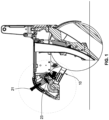
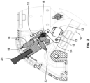
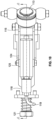
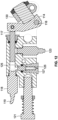
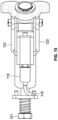
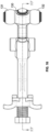
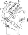
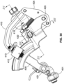
- Each row unit may be provided with its own valves and associated control system. This design may use a small hydraulic ram 406 to perform what would typically be a manual depth adjustment. The ram 406 pushes on a rocker arm 404, which is connected to a link arm 410, which is connected to a slider piece 412. The slider piece 412 is connected to the planter row unit depth adjustment handle and is free to move throughout the same adjustment range that the handle could be moved manually to effect a depth adjustment.
- the distance sensor 411 produces an output signal corresponding to the position of the piston within the hydraulic cylinder, which changes when the depth of the opening disc changes relative to the elevation of the gauge wheel. For example, if the soil engaged by the opening disc becomes harder, the depth of the opening disc becomes smaller unless the down pressure applied to the opening disc is increased. Conversely, if the soil engaged by the opening disc becomes softer, the depth of the opening disc becomes greater unless the down pressure applied to the opening disc is decreased. Thus, the position signal from the hydraulic cylinder actually represents the depth of the opening disc.
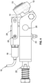
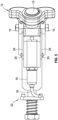
- the small hydraulic ram 406 performs what would typically be a manual depth adjustment.
- the ram 406 pushes on a rocker arm 404, which is connected to a link arm 410, which is connected to a slider/depth adjuster 412.
- the slider/depth adjuster 412 is free to move through the same adjustment range that the conventional depth adjustment handle could be moved manually to effect a depth adjustment.
- the inductive distance sensor 411 that moves closer or farther away from a metal cam target 424 as the slider/depth adjuster 412 is moved throughout its adjustment range.
- the distance sensor 411 produces an output signal that is sent to an electronic controller that compares the signal from the distance sensor 411 with a desired depth value entered by the operator of the planter, as described in more detail below.
- a variety of linear or angular position sensors could be used in place of the illustrated distance sensor, which is preferred for its environmental protection and low cost.
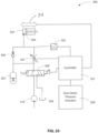
- a controller compares the actual depth with the desired depth, it produces an output signal that controls a pair of valves that can be opened and closed to adjust the pressure in the hydraulic cylinder that receives the ram 406. Changing this pressure extends or retracts the ram 406 to move the slider/depth adjuster 412 to the desired position. Thus, if the position of the ram 406 falls out of tolerance, the system will automatically open and close the valves to maintain the correct setting.
- a pressure sensor 415 that measures the pressure inside a hydraulic cylinder 408 that receives the ram 406. It can be seen that the force exerted on the ground by the gauge wheels is transmitted from the tires to the gauge wheel arms 407, both of which pivot and are supported by the pivoting equalizer 400.
- This equalizer 400 is connected to the slider/depth adjuster 412, which is connected to the link arm 410, which is connected to the rocker arm 404, which in turn contacts the ram 406, which in turn compresses the fluid in the cylinder 406, which is measured by a pressure sensor 415.
- the pressure inside the cylinder 406 is equivalent to the force on the gauge wheels. In this way, a single device accomplishes both depth adjustment and gauge wheel force measurement, and eliminates the need for the typical strain gauge.
- the planting machine When planting an agricultural field with seeds, it is important to control the planting depth in real time as the planting machine traverses the field, because it is critical that the seeds all be planted into moisture so that each seed emerges from the soil at the same time.
- the depth of the seed can be changed based on some type of moisture sensor system, or even based on a satellite or drone system that is able to detect changes in the soil chemistry that would make it desirable to change the depth of the planted seed in different areas of the field.
- An objective of the present invention is to provide a planting system that enables the operator to select a desired planting depth setting, and then automatically maintains the actual planting depth within a selected range above and below the selected depth.
- a pair of valves are controlled to open and close to extend or retract the ram of a hydraulic cylinder to move a slider/depth adjuster to the desired position. If the position of the slider/depth adjuster falls out of tolerance, the system automatically opens and closes the valve to maintain the correct setting.
- Each row unit may be provided with its own valves and associated control system.
- the pressure inside the cylinder 408 is equivalent to the force on the gauge wheels.
- a single device can provide both depth adjustment and gauge wheel force measurement, without the need for the typical strain gauge.
- the system allows fluid pressure to be used both to change the depth that the seed is planted in the ground and how hard the planter gauge wheels are pushing on the ground in a single device.
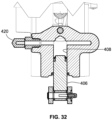
- a fluid port 420 in the fluid chamber 408 is connected to one or more valves to allow hydraulic fluid to be added to or removed from the chamber 408 to change the angle of the opener disc relative to the gauge wheel.
- the distance sensor 411 produces an output signal representing the position of the cutting wheel support arm along the arcuate slot. That position changes as the angle between the two support arm changes with changes in the depth of the opener disc relative to the elevation of the gauge wheel (the soil surface).
- the output signal from the distance sensor 411 will be referred to as the "seed depth” signal because the depth of the opener disc determines the depth of the furrow in which the seed is planted.
- the position sensor produces an output signal corresponding to the position of the piston within the hydraulic cylinder, which changes when the depth of the opener disc changes relative to the elevation of the gauge wheel. For example, if the soil engaged by the opening disc becomes harder, the depth of the opening disc becomes smaller unless the down pressure applied to the opening disc is increased. Conversely, if the soil engaged by the opening disc becomes softer, the depth of the opening disc becomes greater unless the down pressure applied to the opening disc is decreased. Thus, the position signal from the hydraulic cylinder actually represents the depth of the opening disc.
- the output signal from the position sensor is supplied to the controller, which determines whether any change in that signal falls within predetermined dead bands on opposite sides of the target value. If a change exceeds a dead band, the controller produces a control signal that increases or decreases the down pressure on the opening disc to maintain the depth of the opening disc within a desired range on both sides of the target value.
- the target value can be changed automatically as the planter traverses a field having variable soil conditions.
- a soil moisture sensor can be used to determine optimum target values in different areas of a field being planted.
- Another example is to use stored data corresponding to the soil properties at different GPS locations in the field to adjust the target value as the planter traverses those locations.
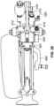
- the gauge wheel support arms 400 push against an equalizer support which is connected to the slider/depth adjuster 412 that slides along an arcuate guide. Movement of the slider/depth adjuster 412 along the arcuate guide moves one end of the link arm 410 that is attached at its other end to the rocker arm 408 mounted for pivoting movement abound a stationary pivot pin 405. The lower end of the rocker arm 408 engages the ram 406 in the hydraulic cylinder 408 that is filled with a pressurized hydraulic fluid.
- the force on the gauge wheels due to the weight of the row unit and applied down force causes the rocker arm 404 to pivot around the pivot bolt 405 and push against the hydraulic ram 406.
- This force on the ram 406 controls the pressure on the fluid in the cylinder 408, so the fluid pressure in the cylinder 408 is proportional to the amount of gauge wheel load.
- This fluid pressure controls the depth of the opener blade by controlling the angle between the support arms for the gauge wheel and the opener blade.
- the pressure of the hydraulic fluid in the cylinder 408 can be adjusted by increasing or decreasing the amount of hydraulic fluid in the cylinder. This is accomplished by a pair of valves that can be opened and closed by electrical signals from an electrical controller.
- the fluid cylinder 408 includes a fluid port 420 that is connected to one or more valves to allow hydraulic fluid to be added to or removed from the cylinder 408 to change the angle of the opener disc relative to the gauge wheel.
- the distance sensor 411 produces an output signal representing the position of the opener disc support arm 402 along an arcuate guide, which changes as the angle between the two support arms changes with changes in the depth of the opener disc relative to the elevation of the gauge wheel (the soil surface).
- the output signal from the distance sensor 411 can be referred to as the "seed depth” signal because the depth of the opener disc determines the depth of the furrow in which the seed is planted.
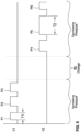
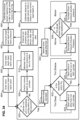
- FIG. 34 is a flow chart of an algorithm for generating signals that control the one or more valves that control the flow of hydraulic fluid in and out of the fluid chamber 408.
- this algorithm calibrates the distance or angle sensor to read the correct seed depth in inches
- step 490 calibrates the pressure sensor 415 to read the gauge wheel force in pounds or kilograms.
- Step 492 computes the target seed depth and down pressure based on the output of step 491 and external soil property data, furrow hardness sensor data and/or moisture sensor data. Then seed depth dead band values are entered at step 493, and down pressure dead band values are entered at step 494.
- Step 500 in this algorithm determines whether the planter row unit is in an operating configuration on the ground, as will be described in detail below.
- step 501 measures the actual seed depth
- step 502 measures the actual gauge wheel load.
- Steps 503 and 504 then determine whether the actual seed depth and the actual gauge wheel load are within their respective dead bands and, if the answer is negative in either case, whether the actual value is above or below that dead band.
- step 505 opens a valve to supply additional hydraulic fluid to the cylinder 406 for a brief time interval. If the actual seed depth is outside the dead band and too shallow, step 505 opens a valve to allow hydraulic fluid to flow out of the cylinder 408 for a brief time interval.
- step 505 opens a valve to supply additional hydraulic fluid to the cylinder 408. If the actual gauge wheel load is above the dead band, step 507 decreases the down pressure actuator pressure. If the actual gauge wheel load is below the dead band, step 108 increases the down pressure actuator pressure. If the actual gauge wheel load is within the dead band, the system returns to step 500 to repeat steps 501-504. When step 500 produces a negative answer, step 509 performs an active air purge process, and step 510 maintains the row unit down pressure at zero for safety.
- a modified system e.g., an agricultural planting system 600 enables an operator to select a desired planting depth setting, and then maintains the actual planting depth within a selected range above and below the selected depth.
- the agricultural planting system 600 is the same as, or similar to, the modified system of FIGS. 26-34 , where like reference numbers are used for like elements, except that the agricultural planting system 600 may further include a GPS device 640.
- the agricultural planting system 600 includes an agricultural planter 630, an opener device, a gauge wheel 635, a GPS device 640, and a controller 650.
- the opener device is mounted on the agricultural planter 630 for engaging the ground of a field.
- the gauge wheel 635 is mounted on the agricultural planter 630 for rotating on the ground of the field.
- the GPS device 640 is communicatively coupled and physically affixed to the agricultural planter 630.
- the agricultural planting system 600 optionally includes a fluid chamber 608 having a fluid port 620 that is connected to one or more valves to allow hydraulic fluid to be added to or removed from the chamber 608 to change the angle of the opener disc relative to the gauge wheel.
- the distance sensor 611 produces an output signal representing the position of the opener disc support arm along the arcuate guide. The position of the opener disc support arm changes with changes in the depth of the opener disc relative to the elevation of the gauge wheel (the soil surface).
- the output signal from the distance sensor 611 is referred to as the "seed depth" signal because the depth of the opener disc determines the depth of the furrow in which the seed is planted.
- the GPS device 640 is configured to determine a location of the agricultural planter 630 in the field.
- the controller 650 is in electrical communication with both the agricultural planter 630 and the GPS device 640.
- the controller 650 has predetermined settings associated with a map of the field.
- the map of the field may consist of stored data corresponding to soil properties at different GPS locations in the field for adjusting the target value as the planter traverses those locations.
- the controller 650 is configured to select a relative elevation of the opener device and the gauge wheel 635 based at least in part on the location determined by the GPS device 640.
- the controller 650 is further configured to produce, based on the location, a signal for adjusting the depth of engagement into the ground of the opener device.
- the relative elevation of the opener device and the gauge wheel 635 is selected automatically in response to the map of the field.
- step 492 computes the target seed depth and down pressure based on the output of step 491 and external soil property data, furrow hardness sensor data and/or moisture sensor data.
- the external soil property data, furrow hardness sensor data and/or moisture sensor data can be represented by the map of the field for determining the target seed depth.
- One benefit of the map is to control the planting depth in real time as the agricultural planter 630 and/or opener traverses the field, because it is critical that the seeds all be planted into moisture so that each seed emerges from the soil at the same time.
- the map of the field includes a topographical map, a soil temperature map, a soil moisture map, or the like, or in any combination thereof.
- the map of the field is associated with the soil properties measured by the plurality of sensors 680.
- the map of the field may consist of stored data, such as external soil property data, soil temperature data, air pressure data, humidity data, furrow hardness data, soil moisture data, or the like. Additionally or alternatively, the map of the field can be updated periodically (e.g., every hour, every day, every week, every month, etc.) according to the soil properties measured by the plurality of sensors.
- the plurality of sensors 680 includes at least one soil moisture sensor.
- the at least one soil moisture sensor 680 can include a local moisture sensor 685 (illustrated in FIG. 35 ) mounted on the agricultural planter 630 and in contact with the ground being engaged by the opener device.
- the controller 650 is configured to produce a signal for adjusting the depth of engagement into the ground of the opener device.
- the map of the field may be updated according to the soil moisture level measured by the local moisture sensor 685 at each GPS location measured by the GPS device 640.
- the map of the field may also be updated to include a seed depth associated with each GPS location.
- Each seed depth at its respective GPS location may be cross-referenced with other seed depths at their respective GPS locations, for determining the relative elevation of the opener device and the gauge wheel 635, based at least in part on (1) the local soil moisture level measured by the local moisture sensor 685, (2) the stored soil moisture data from the map of the field, and/or (3) the soil moisture level measured by the plurality of remote sensors 680.
Landscapes
- Life Sciences & Earth Sciences (AREA)
- Soil Sciences (AREA)
- Environmental Sciences (AREA)
- Engineering & Computer Science (AREA)
- Mechanical Engineering (AREA)
- Lifting Devices For Agricultural Implements (AREA)
Applications Claiming Priority (2)
| Application Number | Priority Date | Filing Date | Title |
|---|---|---|---|
| US16/365,360 US11197411B2 (en) | 2014-11-07 | 2019-03-26 | Agricultural planting system with automatic depth control |
| EP20162196.8A EP3714671B1 (de) | 2019-03-26 | 2020-03-10 | Landwirtschaftliches pflanzsystem mit automatischer tiefenregelung |
Related Parent Applications (1)
| Application Number | Title | Priority Date | Filing Date |
|---|---|---|---|
| EP20162196.8A Division EP3714671B1 (de) | 2019-03-26 | 2020-03-10 | Landwirtschaftliches pflanzsystem mit automatischer tiefenregelung |
Publications (2)
| Publication Number | Publication Date |
|---|---|
| EP4581920A2 true EP4581920A2 (de) | 2025-07-09 |
| EP4581920A3 EP4581920A3 (de) | 2025-11-12 |
Family
ID=69804530
Family Applications (2)
| Application Number | Title | Priority Date | Filing Date |
|---|---|---|---|
| EP20162196.8A Active EP3714671B1 (de) | 2019-03-26 | 2020-03-10 | Landwirtschaftliches pflanzsystem mit automatischer tiefenregelung |
| EP25178880.8A Pending EP4581920A3 (de) | 2019-03-26 | 2020-03-10 | Landwirtschaftliches pflanzsystem mit automatischer tiefensteuerung |
Family Applications Before (1)
| Application Number | Title | Priority Date | Filing Date |
|---|---|---|---|
| EP20162196.8A Active EP3714671B1 (de) | 2019-03-26 | 2020-03-10 | Landwirtschaftliches pflanzsystem mit automatischer tiefenregelung |
Country Status (1)
| Country | Link |
|---|---|
| EP (2) | EP3714671B1 (de) |
Families Citing this family (1)
| Publication number | Priority date | Publication date | Assignee | Title |
|---|---|---|---|---|
| CN115030939B (zh) * | 2022-06-02 | 2023-08-01 | 中国农业大学 | 一种电动拖拉机用直驱式电液悬挂系统及其控制方法 |
Family Cites Families (2)
| Publication number | Priority date | Publication date | Assignee | Title |
|---|---|---|---|---|
| UA118026C2 (uk) * | 2013-03-14 | 2018-11-12 | Пресіжн Плентінг Елелсі | Система (варіанти), спосіб (варіанти) і пристрій керування глибиною борозни сільськогосподарського знаряддя і контролю ґрунту |
| EP3420790A1 (de) * | 2017-06-29 | 2019-01-02 | Dawn Equipment Company | Landwirtschaftliches pflanzsystem mit automatischer andruckregelung |
-
2020
- 2020-03-10 EP EP20162196.8A patent/EP3714671B1/de active Active
- 2020-03-10 EP EP25178880.8A patent/EP4581920A3/de active Pending
Also Published As
| Publication number | Publication date |
|---|---|
| EP3714671B1 (de) | 2025-06-04 |
| EP3714671A1 (de) | 2020-09-30 |
| EP4581920A3 (de) | 2025-11-12 |
Similar Documents
| Publication | Publication Date | Title |
|---|---|---|
| US11197411B2 (en) | Agricultural planting system with automatic depth control | |
| US10582653B2 (en) | Agricultural planting system with automatic depth control | |
| US10444774B2 (en) | Agricultural system | |
| US9848522B2 (en) | Agricultural system | |
| US11064651B2 (en) | Down pressure adjustment device and method for use with a disc opener assembly of an agricultural implement | |
| AU2021290412B2 (en) | Agricultural trench depth systems, methods, and apparatus | |
| US20220369538A1 (en) | Air seeder press wheel and closing wheel force control | |
| US10251333B2 (en) | Agricultural system | |
| CA2889716C (en) | Automatic down pressure adjustment system for set of ganged disc openers | |
| US9026321B2 (en) | System and method for controlling soil finish from an agricultural implement | |
| EP2554037B1 (de) | System für zusätzliche Anpresskraft, Bodenbearbeitungsgerät damit und Verfahren | |
| EP2554036A1 (de) | System für zusätzliche Anpresskraft und Bodenbearbeitungsgerät damit | |
| EP3420790A1 (de) | Landwirtschaftliches pflanzsystem mit automatischer andruckregelung | |
| MX2014006131A (es) | Transferencia de peso de implemento con control de retroalimentacion. | |
| EP3714671B1 (de) | Landwirtschaftliches pflanzsystem mit automatischer tiefenregelung | |
| CA3009363A1 (en) | Agricultural planting system with automatic depth control | |
| EP4082316B1 (de) | Schliesssystem | |
| US20230108066A1 (en) | Control system for planter weight transfer systems |
Legal Events
| Date | Code | Title | Description |
|---|---|---|---|
| PUAI | Public reference made under article 153(3) epc to a published international application that has entered the european phase |
Free format text: ORIGINAL CODE: 0009012 |
|
| STAA | Information on the status of an ep patent application or granted ep patent |
Free format text: STATUS: THE APPLICATION HAS BEEN PUBLISHED |
|
| AC | Divisional application: reference to earlier application |
Ref document number: 3714671 Country of ref document: EP Kind code of ref document: P |
|
| AK | Designated contracting states |
Kind code of ref document: A2 Designated state(s): AL AT BE BG CH CY CZ DE DK EE ES FI FR GB GR HR HU IE IS IT LI LT LU LV MC MK MT NL NO PL PT RO RS SE SI SK SM TR |
|
| REG | Reference to a national code |
Ref country code: DE Ref legal event code: R079 Free format text: PREVIOUS MAIN CLASS: A01C0007200000 Ipc: A01B0079000000 |
|
| PUAL | Search report despatched |
Free format text: ORIGINAL CODE: 0009013 |
|
| AK | Designated contracting states |
Kind code of ref document: A3 Designated state(s): AL AT BE BG CH CY CZ DE DK EE ES FI FR GB GR HR HU IE IS IT LI LT LU LV MC MK MT NL NO PL PT RO RS SE SI SK SM TR |
|
| RIC1 | Information provided on ipc code assigned before grant |
Ipc: A01B 79/00 20060101AFI20251008BHEP Ipc: A01C 5/06 20060101ALI20251008BHEP Ipc: A01C 7/20 20060101ALI20251008BHEP |
|
| RAP3 | Party data changed (applicant data changed or rights of an application transferred) |
Owner name: DEERE & COMPANY |