EP4581918A1 - Verfahren zur bewertung einer furche - Google Patents
Verfahren zur bewertung einer furche Download PDFInfo
- Publication number
- EP4581918A1 EP4581918A1 EP24222964.9A EP24222964A EP4581918A1 EP 4581918 A1 EP4581918 A1 EP 4581918A1 EP 24222964 A EP24222964 A EP 24222964A EP 4581918 A1 EP4581918 A1 EP 4581918A1
- Authority
- EP
- European Patent Office
- Prior art keywords
- camera
- furrow
- depth
- time interval
- quality
- Prior art date
- Legal status (The legal status is an assumption and is not a legal conclusion. Google has not performed a legal analysis and makes no representation as to the accuracy of the status listed.)
- Pending
Links
Images






Classifications
-
- A—HUMAN NECESSITIES
- A01—AGRICULTURE; FORESTRY; ANIMAL HUSBANDRY; HUNTING; TRAPPING; FISHING
- A01C—PLANTING; SOWING; FERTILISING
- A01C21/00—Methods of fertilising, sowing or planting
-
- G—PHYSICS
- G06—COMPUTING OR CALCULATING; COUNTING
- G06T—IMAGE DATA PROCESSING OR GENERATION, IN GENERAL
- G06T7/00—Image analysis
- G06T7/0002—Inspection of images, e.g. flaw detection
-
- A—HUMAN NECESSITIES
- A01—AGRICULTURE; FORESTRY; ANIMAL HUSBANDRY; HUNTING; TRAPPING; FISHING
- A01B—SOIL WORKING IN AGRICULTURE OR FORESTRY; PARTS, DETAILS, OR ACCESSORIES OF AGRICULTURAL MACHINES OR IMPLEMENTS, IN GENERAL
- A01B63/00—Lifting or adjusting devices or arrangements for agricultural machines or implements
- A01B63/002—Devices for adjusting or regulating the position of tools or wheels
- A01B63/008—Vertical adjustment of tools
-
- A—HUMAN NECESSITIES
- A01—AGRICULTURE; FORESTRY; ANIMAL HUSBANDRY; HUNTING; TRAPPING; FISHING
- A01C—PLANTING; SOWING; FERTILISING
- A01C7/00—Sowing
- A01C7/08—Broadcast seeders; Seeders depositing seeds in rows
- A01C7/10—Devices for adjusting the seed-box ; Regulation of machines for depositing quantities at intervals
- A01C7/102—Regulating or controlling the seed rate
- A01C7/105—Seed sensors
-
- A—HUMAN NECESSITIES
- A01—AGRICULTURE; FORESTRY; ANIMAL HUSBANDRY; HUNTING; TRAPPING; FISHING
- A01C—PLANTING; SOWING; FERTILISING
- A01C7/00—Sowing
- A01C7/20—Parts of seeders for conducting and depositing seed
- A01C7/201—Mounting of the seeding tools
- A01C7/203—Mounting of the seeding tools comprising depth regulation means
-
- A—HUMAN NECESSITIES
- A01—AGRICULTURE; FORESTRY; ANIMAL HUSBANDRY; HUNTING; TRAPPING; FISHING
- A01C—PLANTING; SOWING; FERTILISING
- A01C7/00—Sowing
- A01C7/20—Parts of seeders for conducting and depositing seed
- A01C7/201—Mounting of the seeding tools
- A01C7/205—Mounting of the seeding tools comprising pressure regulation means
-
- G—PHYSICS
- G06—COMPUTING OR CALCULATING; COUNTING
- G06T—IMAGE DATA PROCESSING OR GENERATION, IN GENERAL
- G06T1/00—General purpose image data processing
- G06T1/0014—Image feed-back for automatic industrial control, e.g. robot with camera
-
- G—PHYSICS
- G06—COMPUTING OR CALCULATING; COUNTING
- G06V—IMAGE OR VIDEO RECOGNITION OR UNDERSTANDING
- G06V10/00—Arrangements for image or video recognition or understanding
- G06V10/98—Detection or correction of errors, e.g. by rescanning the pattern or by human intervention; Evaluation of the quality of the acquired patterns
-
- G—PHYSICS
- G06—COMPUTING OR CALCULATING; COUNTING
- G06V—IMAGE OR VIDEO RECOGNITION OR UNDERSTANDING
- G06V20/00—Scenes; Scene-specific elements
- G06V20/10—Terrestrial scenes
- G06V20/188—Vegetation
-
- A—HUMAN NECESSITIES
- A01—AGRICULTURE; FORESTRY; ANIMAL HUSBANDRY; HUNTING; TRAPPING; FISHING
- A01C—PLANTING; SOWING; FERTILISING
- A01C5/00—Making or covering furrows or holes for sowing, planting or manuring
- A01C5/06—Machines for making or covering drills or furrows for sowing or planting
- A01C5/062—Devices for making drills or furrows
- A01C5/064—Devices for making drills or furrows with rotating tools
-
- G—PHYSICS
- G06—COMPUTING OR CALCULATING; COUNTING
- G06T—IMAGE DATA PROCESSING OR GENERATION, IN GENERAL
- G06T2200/00—Indexing scheme for image data processing or generation, in general
- G06T2200/24—Indexing scheme for image data processing or generation, in general involving graphical user interfaces [GUIs]
-
- G—PHYSICS
- G06—COMPUTING OR CALCULATING; COUNTING
- G06T—IMAGE DATA PROCESSING OR GENERATION, IN GENERAL
- G06T2207/00—Indexing scheme for image analysis or image enhancement
- G06T2207/30—Subject of image; Context of image processing
- G06T2207/30168—Image quality inspection
-
- G—PHYSICS
- G06—COMPUTING OR CALCULATING; COUNTING
- G06T—IMAGE DATA PROCESSING OR GENERATION, IN GENERAL
- G06T2207/00—Indexing scheme for image analysis or image enhancement
- G06T2207/30—Subject of image; Context of image processing
- G06T2207/30181—Earth observation
- G06T2207/30188—Vegetation; Agriculture
Definitions
- the present disclosure relates to an apparatus, method and system for evaluating a furrow created by an agricultural machine.
- Planter row units are commonly used by farmers to plant seed and/or a corresponding commodity in the ground. Planter row units often include various ground-engaging tools that assist in the commodity or seed deposition process by, for example, opening furrows to form trenches, placing or depositing commodity and seed in the trenches, packing the soil, and closing the furrows or trenches over the newly-deposited commodity and seed. From the operator station, it is difficult to assess several essential factors which govern seed planting quality.
- These factors include but are not limited to a seed's final resting place, spacing between planted seeds, depths of the planted seeds, furrow integrity, which may be represented by a desirable furrow shape and structure, and seed to soil contact, which may be represented by seedbed quality metrics indicating soil content materials.
- One option to increase efficiency, increase productivity, and increase the quality of trench formation and commodity placement by planter row units is to add one or more cameras to the planter row unit to monitor and detect seed planting quality such that a user from the operator station of the planter row unit or elsewhere can see the seed furrow and/or a visual representation of the seed furrow including information relating to commodity depth, commodity depth offset, and furrow quality.
- the discussion above is merely provided for general background information and is not intended to be used as an aid in determining the scope of the claimed subject matter.
- one aspect of this disclosure provides a method for providing camera data to the user of the agricultural machine and, optionally, feedback regarding the confidence for which the provided image data can be analyzed.
- the confidence may be about 100.
- the provided confidence may only be 50.
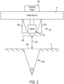
- the camera 62 may be a distance 204 from a ground plane 206.
- the ground plane 206 may generally represent the planar orientation of the surface of the unopened ground G surrounding the furrow 202.
- the distance 204 may be generally known based on the fixed positioning of the camera 62 to the planter row unit 14 and the planting depth of the planter row unit 14. In other words, the camera 62 may typically move in a horizontal plane 208 parallel to the ground plane 206 and adjustments to the planting depth of the planter row unit 14 will adjust the distance 204 of the camera 62 from the ground G.
- the positioning system 304 may be used by the computing device 306 to determine the displacement of the camera 62 between image captures. For example, if the camera 62 is mounted to a tool bar of the work machine 300, the computing device 306 may utilize vehicle speed between image captures to determine camera 62 displacement between image captures. Similarly, the computing device 306 may record the geographic location of the camera 62 or the work machine 300 and determine the geographic distance displacement between the image captures.
- the camera 62 and positioning system 304 may be communicatively coupled to the computing device 306. Further, the computing device 306 may be communicatively coupled to an output 308.
- the output 308 may be a visual display in a cab of the work machine 300, an audio device, or a haptic feedback device that may be selectively engaged by the computing device 306 to provide information about the agricultural work machine 300.
- the output 308 may be a remote device to be used by a remote user.
- the output 308 may provide access to a remote database such as a cloud-based system.
- the computing device 306 may be, or include, the controller discussed herein. Alternatively, the computing device 306 may be any control module or the like on the agricultural work machine 300. Accordingly, the computing device 306 contemplated herein may be any device capable of analyzing inputs and providing outputs as discussed herein.
- a camera confidence logic 400 is applied to the captured image data for a given time interval to provide feedback containing a camera confidence. More specifically, in box 402 the computing device 306 may obtain image data from the camera for a given time interval.
- the given time interval may be any rolling time interval and in one example the time interval may be plus and minus 5 seconds for any given recorded image.
- the camera 62 may continuously record image data during a planting operation. A time interval may be generated for any point in time during the planting operation wherein the image data for five seconds before and after the point in time is considered when evaluating camera confidence.
- the provided feedback may include directions to alleviate poor camera confidence.
- the provided feedback may provide instructions to use adjacent row sensors for the requested data, recommend cleaning the camera, recommend reducing speed to reduce dust, recommend changing row cleaner settings, recommend changing downforce settings, recommend changing shield height setting for sunlight intrusion, and/or recommend changing machine direction to reduce sunlight intrusion among other things.
- furrow depth consistency logic 500 is illustrated.
- the average of these readings can appropriately be used to represent the furrow depth as a whole.
- the average of available readings may not represent the furrow depth as a whole. Accordingly, furrow consistency is an additional metric that can be considered to understand furrow performance, availability of depth readings, and support decision making around confirming seed placement among other things.
- the furrow depth consistency may be generated based on the number of flagged data points for the time interval.
- the furrow depth consistency may be the percentage of furrow depth values that were within the expected threshold range for the time interval.
- the furrow depth consistency may be provided in box 510.
- the furrow depth consistency may be provided to a user through a user interface similar to the camera confidence discussed herein. More specifically, a user interface may illustrate the measure furrow depth along with showing a furrow depth consistency bar thereunder. If the furrow depth consistency goes down, the bar may become shorter and/or obtain hashing. Further, the provided feedback may be directed towards other automated systems of the work machine as described herein for the camera confidence.
- a visual display is provided within operator station (i.e., cab) of an agricultural machine.
- the output 308 may be a remote device with a visual display to be used by a user.
- the remote device may include but is not limited to a personal device (e.g., cellphone, tablet, AR/VR headset and the like) accessible by a user at one or more locations, e.g., at the user's home, office, or even within the operator station of the agricultural machine.
- the present disclosure provides for apparatuses, methods and systems to calibrate, configure, measure and control of planting depth within furrow 202 to happen inside the operator station cab using a visual display.
- the visual display communicating information on the furrow profile, planting depth targets and controlled depths and further allowing for calibration, configuration and adjustment thereof.
- Commodity depth offset generally represents estimated commodity depths where the offset is the difference between the average furrow depth system readings (for example through visualization system 60) and the average depth of a planted commodity/seed observed when manually checking depth.
- Commodity depth offset icons and user interfaces in FIGs. 6a-6d thus provide an important calibration step to provide user confidence in visualization system 60.
- adjusting the commodity depth offset via icon commodity depth offset icons in FIGs. 6a-6d does not necessarily change planter row unit depth - which is done via other conventional methods of depth control of a planter row unit 14.
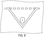
- visual displays are provided pertaining to the definition, entry, and adjustment of the difference between at least two of the bottom of the furrow FB, ground G and the measured position of the commodity S in the furrow.
- the commodity depth offset may vary due to seed size, speed of planting, gauge wheel down force, soil type, or other factors.
- the commodity depth offset icon communicates to the user that a difference in depths exists (furrow bottom FB and commodity S). Using this information, a user may configure a corresponding offset after measuring the commodity S depth relative to the surface G as shown FIG. 6b and 6d represented by bi-directional arrow A. In another example, as shown in FIG. 6c represented by bi-directional arrow C, a user may configure a corresponding offset after measuring the commodity S depth relative to the bottom FB of the furrow 202.
- the commodity depth offset allows the user to view planting depth during planting in terms of commodity depth, as calculated from measured or controlled furrow depths and adjust this value before, during or after the planting operation.
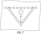
- FIG. 7 a cutaway view from FIG. 6a of an exemplary representation of a planting depth icon is shown for commodity depth offset.
- the planting depth icon providing a clear indicator of configuration options of the visualization system 60, including in lists of systems within the display.
- the bi-directional arrow represents multiple attributes such as shallower or deeper planting depth of the commodity S in furrow 202 with respect to the ground G and/or furrow bottom FB in furrow 202.
- the planting depth icon of FIG. 7 is flexible in use to represent configured planting depths in the furrow 202.
- FIG. 9 a cutaway view from FIG. 6a of an exemplary representation of a planting depth icon is shown for commodity depth offset.
- FIG.9 shows a representation of possible configurations to adjust planting depth such that the commodity S is planted shallower (i.e., closer to ground G and/or further from furrow bottom FB). Due to the nature of depth being below ground G (or ground plane G from FIG. 2 ), a decrease in value indicates a shallower planting depth of the commodity S. Alternatively, the planting depth may also be measured from the bottom FB of the furrow or trench 202.
- ground level or ground plane G
- additional indication aids the usability of the system to show whether an increase or decrease in value corresponds to a shallower planting depth.
- the icon of FIG. 9 thus provides additional context and information to changes in system target or controlled depths.
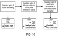
- FIG. 12 an example of user interface from a visual display according to the logic flow of FIG. 10 is shown.
- Visual display communicating information on the furrow profile, allowing for calibration, configuration and adjustment thereof.
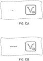
- FIGs. 13a-13b show cutaway views of the display screen or portion of FIG. 12 , specifically showing information related to the furrow quality.
- visualization system 60 may utilize camera images from camera 62 to detect laser readings of depth and/or shape of the furrow 202.
- the camera images/data from camera 62 may be obscured due to dust, mud, or sunlight conditions, and/or the laser reading of depth may not be available. If a high enough percentage of images are unavailable (as previously discussed and shown in FIGs. 4-5 ), the operator will be notified via an icon representing the camera icon 62a.
- the furrow camera icon 202a will be shown at an initial threshold (see FIG. 11a) to alert the user to the degradation of the camera images/data, and at a second threshold (see FIG.
- the furrow camera icon provides context to unavailable data, to help the operator diagnose the current state of the system and the furrow environment. By additionally showing the furrow camera icon before the depth reading is unavailable, the operator is provided more advanced notice to monitor furrow environment, act, and have more appropriate expectations for future data states.
Landscapes
- Life Sciences & Earth Sciences (AREA)
- Engineering & Computer Science (AREA)
- Soil Sciences (AREA)
- Environmental Sciences (AREA)
- Theoretical Computer Science (AREA)
- General Physics & Mathematics (AREA)
- Physics & Mathematics (AREA)
- Multimedia (AREA)
- Quality & Reliability (AREA)
- Mechanical Engineering (AREA)
- Robotics (AREA)
- Health & Medical Sciences (AREA)
- General Health & Medical Sciences (AREA)
- Computer Vision & Pattern Recognition (AREA)
- Management, Administration, Business Operations System, And Electronic Commerce (AREA)
- Image Processing (AREA)
Applications Claiming Priority (2)
| Application Number | Priority Date | Filing Date | Title |
|---|---|---|---|
| US202463618695P | 2024-01-08 | 2024-01-08 | |
| US18/985,701 US20250225634A1 (en) | 2024-01-08 | 2024-12-18 | Apparatus, method and system for evaluating a furrow |
Publications (1)
| Publication Number | Publication Date |
|---|---|
| EP4581918A1 true EP4581918A1 (de) | 2025-07-09 |
Family
ID=94083210
Family Applications (1)
| Application Number | Title | Priority Date | Filing Date |
|---|---|---|---|
| EP24222964.9A Pending EP4581918A1 (de) | 2024-01-08 | 2024-12-23 | Verfahren zur bewertung einer furche |
Country Status (3)
| Country | Link |
|---|---|
| US (1) | US20250225634A1 (de) |
| EP (1) | EP4581918A1 (de) |
| AU (1) | AU2025200053A1 (de) |
Citations (3)
| Publication number | Priority date | Publication date | Assignee | Title |
|---|---|---|---|---|
| US20220000008A1 (en) * | 2020-07-01 | 2022-01-06 | Deere & Company | Implement mounted sensors sensing surface/furrow characteristics and control |
| US20230240164A1 (en) * | 2019-05-10 | 2023-08-03 | Great Plains Manufacturing, Inc. | Agricultural implement with vision sensors |
| WO2023158569A1 (en) * | 2022-02-08 | 2023-08-24 | Deere & Company | Structured-light-based trench profile measurement for planter row unit |
-
2024
- 2024-12-18 US US18/985,701 patent/US20250225634A1/en active Pending
- 2024-12-23 EP EP24222964.9A patent/EP4581918A1/de active Pending
-
2025
- 2025-01-06 AU AU2025200053A patent/AU2025200053A1/en active Pending
Patent Citations (3)
| Publication number | Priority date | Publication date | Assignee | Title |
|---|---|---|---|---|
| US20230240164A1 (en) * | 2019-05-10 | 2023-08-03 | Great Plains Manufacturing, Inc. | Agricultural implement with vision sensors |
| US20220000008A1 (en) * | 2020-07-01 | 2022-01-06 | Deere & Company | Implement mounted sensors sensing surface/furrow characteristics and control |
| WO2023158569A1 (en) * | 2022-02-08 | 2023-08-24 | Deere & Company | Structured-light-based trench profile measurement for planter row unit |
Also Published As
| Publication number | Publication date |
|---|---|
| AU2025200053A1 (en) | 2025-07-24 |
| US20250225634A1 (en) | 2025-07-10 |
Similar Documents
| Publication | Publication Date | Title |
|---|---|---|
| EP4427566A1 (de) | Verfahren zur bewertung der bereitgestellten datengenauigkeit für eine landwirtschaftliche arbeitsmaschine | |
| AU2017355315B2 (en) | Work layer imaging and analysis for implement monitoring, control and operator feedback | |
| EP3150045B1 (de) | Bodeneigenschaftssensoren an bodeneingriffselementen einer sämaschine | |
| CN106556337B (zh) | 农业播种深度传感器 | |
| EP4332898A1 (de) | Grabenprofilbestimmung durch bewegung | |
| EP4139674B1 (de) | Hoch- und niederfrequente boden- und pflanzenanalysesysteme mit integrierten messungen | |
| UA126552C2 (uk) | Спосіб визначення та надання рекомендації щодо норми висіву насіння рослин на полі | |
| AU2013299359A1 (en) | Systems and methods for control, monitoring and mapping of agricultural applications | |
| US11310953B2 (en) | System and method for calibrating load sensors of an agricultural implement | |
| EP4198887A1 (de) | Grabenprofilbestimmung durch bewegung | |
| EP4581918A1 (de) | Verfahren zur bewertung einer furche | |
| EP4581921A1 (de) | Vorrichtung, verfahren und system zur bewertung einer furche | |
| EP4581919A2 (de) | Methode zur bewertung einer landwirtschaftlichen saatfurche | |
| BR102025000223A2 (pt) | Métodos para avaliar um sulco criado por uma máquina agrícola e a qualidade dos valores providos para uma máquina agrícola | |
| BR102025000249A2 (pt) | Método para avaliar um sulco formado por uma máquina agrícola, e, método para avaliar a qualidade de valores providos para uma máquina agrícola | |
| BR102025000244A2 (pt) | Método para avaliar um sulco criado por uma máquina agrícola, e, método para avaliar a qualidade dos valores providos para uma máquina agrícola | |
| CA3207169A1 (en) | Furrow visualization | |
| BR102024003614A2 (pt) | Método para avaliar a exatidão de dados providos para uma máquina agrícola | |
| CA3164548C (en) | High and low frequency soil and plant analysis systems with integrated measurements | |
| CA3206033A1 (en) | Trench profile determination by motion | |
| US12336444B2 (en) | Residue manager adjustment system and method |
Legal Events
| Date | Code | Title | Description |
|---|---|---|---|
| PUAI | Public reference made under article 153(3) epc to a published international application that has entered the european phase |
Free format text: ORIGINAL CODE: 0009012 |
|
| STAA | Information on the status of an ep patent application or granted ep patent |
Free format text: STATUS: THE APPLICATION HAS BEEN PUBLISHED |
|
| AK | Designated contracting states |
Kind code of ref document: A1 Designated state(s): AL AT BE BG CH CY CZ DE DK EE ES FI FR GB GR HR HU IE IS IT LI LT LU LV MC ME MK MT NL NO PL PT RO RS SE SI SK SM TR |
|
| STAA | Information on the status of an ep patent application or granted ep patent |
Free format text: STATUS: REQUEST FOR EXAMINATION WAS MADE |
|
| 17P | Request for examination filed |
Effective date: 20251224 |