EP4580310A2 - Verfahren und vorrichtung zur handhabung von funkverbindungsfehlern - Google Patents
Verfahren und vorrichtung zur handhabung von funkverbindungsfehlern Download PDFInfo
- Publication number
- EP4580310A2 EP4580310A2 EP25176291.0A EP25176291A EP4580310A2 EP 4580310 A2 EP4580310 A2 EP 4580310A2 EP 25176291 A EP25176291 A EP 25176291A EP 4580310 A2 EP4580310 A2 EP 4580310A2
- Authority
- EP
- European Patent Office
- Prior art keywords
- node
- iab node
- backhaul link
- iab
- signaling message
- Prior art date
- Legal status (The legal status is an assumption and is not a legal conclusion. Google has not performed a legal analysis and makes no representation as to the accuracy of the status listed.)
- Pending
Links
Images


Classifications
-
- H—ELECTRICITY
- H04—ELECTRIC COMMUNICATION TECHNIQUE
- H04W—WIRELESS COMMUNICATION NETWORKS
- H04W24/00—Supervisory, monitoring or testing arrangements
- H04W24/04—Arrangements for maintaining operational condition
-
- H—ELECTRICITY
- H04—ELECTRIC COMMUNICATION TECHNIQUE
- H04W—WIRELESS COMMUNICATION NETWORKS
- H04W76/00—Connection management
- H04W76/10—Connection setup
- H04W76/19—Connection re-establishment
-
- H—ELECTRICITY
- H04—ELECTRIC COMMUNICATION TECHNIQUE
- H04W—WIRELESS COMMUNICATION NETWORKS
- H04W48/00—Access restriction; Network selection; Access point selection
- H04W48/20—Selecting an access point
-
- H—ELECTRICITY
- H04—ELECTRIC COMMUNICATION TECHNIQUE
- H04W—WIRELESS COMMUNICATION NETWORKS
- H04W76/00—Connection management
- H04W76/20—Manipulation of established connections
- H04W76/27—Transitions between radio resource control [RRC] states
-
- H—ELECTRICITY
- H04—ELECTRIC COMMUNICATION TECHNIQUE
- H04W—WIRELESS COMMUNICATION NETWORKS
- H04W76/00—Connection management
- H04W76/30—Connection release
-
- H—ELECTRICITY
- H04—ELECTRIC COMMUNICATION TECHNIQUE
- H04W—WIRELESS COMMUNICATION NETWORKS
- H04W80/00—Wireless network protocols or protocol adaptations to wireless operation
- H04W80/02—Data link layer protocols
-
- H—ELECTRICITY
- H04—ELECTRIC COMMUNICATION TECHNIQUE
- H04W—WIRELESS COMMUNICATION NETWORKS
- H04W88/00—Devices specially adapted for wireless communication networks, e.g. terminals, base stations or access point devices
- H04W88/14—Backbone network devices
-
- H—ELECTRICITY
- H04—ELECTRIC COMMUNICATION TECHNIQUE
- H04W—WIRELESS COMMUNICATION NETWORKS
- H04W88/00—Devices specially adapted for wireless communication networks, e.g. terminals, base stations or access point devices
- H04W88/08—Access point devices
- H04W88/085—Access point devices with remote components
-
- H—ELECTRICITY
- H04—ELECTRIC COMMUNICATION TECHNIQUE
- H04W—WIRELESS COMMUNICATION NETWORKS
- H04W92/00—Interfaces specially adapted for wireless communication networks
- H04W92/04—Interfaces between hierarchically different network devices
- H04W92/14—Interfaces between hierarchically different network devices between access point controllers and backbone network device
Definitions
- the present disclosure generally relates to wireless communication technology, especially for handling a radio link failure in a wireless communication system.
- RNs Relay Nodes
- 3GPP 3rd Generation Partnership Project
- RNs Relay Nodes
- One of the main objectives for deploying RNs is to enhance coverage area of a Base Station (hereinafter referred to as BS) by improving throughput of a mobile device (also known as a user equipment (UE)) that locates in a coverage hole or far from the base station resulting in low signal quality.
- BS Base Station
- UE user equipment
- a BS that can provide connection to at least one RN is called a Donor BS.
- a RN is connected to a Donor BS by a backhaul link.
- the RN may hop through one or more RNs before reaching the Donor BS, or may be directly connected to the Donor BS.
- a procedure for selecting a candidate node to re-establish a backhaul link in response to a failure in the backhaul link is desirable.
- One embodiment of the present disclosure provides a method, comprising: transmitting, at a communication device, a signaling message indicating a failure in a backhaul link.
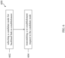
- Yet another embodiment of the present disclosure provides a method, comprising: selecting, at a communication device, a candidate node for backhaul link re-establishment in response to a failure in a backhaul link; and transmitting, at the communication device, a re-establishment request to the candidate node.
- Yet another embodiment of the present disclosure provides a non-transitory computer-readable medium having stored thereon computer-executable instructions to cause a processor to implement the above method.
- Yet another embodiment of the present disclosure provides an apparatus, comprising: a non-transitory computer-readable medium having stored thereon computer-executable instructions to cause a processor to implement the above method; a receiving circuitry; a transmitting circuitry; and a processor coupled to the non-transitory computer-readable medium, the receiving circuitry and the transmitting circuitry.
- Yet another embodiment of the present disclosure provides a method, comprising: receiving, from a communication device, a signaling message indicating a failure in a backhaul link.
- Yet another embodiment of the present disclosure provides a non-transitory computer-readable medium having stored thereon computer-executable instructions to cause a processor to implement the above method.
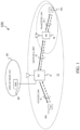
- FIG. 1 illustrates a wireless communication system 100 according to an embodiment of the present disclosure.
- the BS 10 operates under the control of a Mobility Management Entity (MME) 40 and is connecting to a Core Network (CN) 50.
- the core network also includes a Home Subscriber Server (HSS) (not shown), which is in communication with the MME.
- the BS 10 may be based, for example, on the standards of Long-Term Evolution (LTE), LTE-Advanced (LTE-A), New Radio (NR), or other suitable standards.
- LTE Long-Term Evolution
- LTE-A LTE-Advanced
- NR New Radio
- the BS 10 may be an eNB or a gNB, and may define one or more cells, such as cell 11.
- UEs 30A and/or 30B may be a computing device, a wearable device, or a mobile device, etc.
- Persons skilled in the art should understand that as the 3GPP (3rd Generation Partnership Project) and the communication technology develop, the terminologies recited in the specification may change, which should not affect the principle of the disclosure.
- 3GPP is envisioning an Integrated Access and Backhaul (IAB) architecture for the 5G (NR) communication networks supporting multi-hop relays. That is, a RN may hop through one or more RNs before reaching the Donor BS. Single hop should be considered a special case of multiple hops. Multi-hop backhauling is beneficial since it provides larger range extension than single-hop backhauling. Higher frequency bands, such as frequency bands above 6 GHz, have limited range of radio signals, and can profit from such larger range extension. Multi-hop backhauling further enables backhauling around obstacles, e.g., buildings in urban environment for in-clutter deployments.
- obstacles e.g., buildings in urban environment for in-clutter deployments.
- the maximum number of hops in a deployment is expected to depend on a plurality of factors such as frequency, cell density, propagation environment, and traffic load. These factors are expected to change over time. As the number of hops increases, scalability issues may arise. For example, performance may degrade and/or signaling load may increase to unacceptable levels.
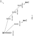
- FIG. 2 illustrates a wireless communication system 200 according to an embodiment of the present disclosure.
- the wireless communication system 200 is comprised of a plurality of nodes, including a Donor node, i.e., IAB Donor, a plurality of IAB nodes, including IAB nodes 0-3, and a plurality of UEs, including UE 0 and UE 1.
- the wireless communication system 200 may also comprise of a plurality of Donor nodes.
- FIG. 3 illustrates a wireless communication system 300 according to an embodiment of the present disclosure.
- the IAB nodes and the UEs may be connected to a Next-Generation Core (NGC).
- NNC Next-Generation Core
- Each IAB node may comprise a Distributed Unit (DU) and a Mobile Termination (MT).
- the IAB nodes may be connected to an upstream IAB node or an IAB donor via the MT, and may be connected to the UEs and a downstream IAB node via the DU.
- the IAB donor may comprise a DU to support UEs and MTs of downstream IAB nodes.
- the IAB donor may further comprise a Centralized Unit (CU) for the DUs of all IAB-nodes and for its own DU.
- the IAB nodes in FIG. 3 may sometimes be referred to as Layer-2 (L2) IAB nodes.
- the IAB nodes in FIG. 2 e.g., IAB nodes 0-3, may be L2 IAB nodes.
- FIG. 4 illustrates a wireless communication system 400 according to an embodiment of the present disclosure.
- the IAB nodes and the UEs may be connected to a NGC.
- Each IAB node may comprise a gNB and a MT.
- the IAB node may be connected to an upstream IAB node or an IAB donor via the MT, and may be connected to the UEs and a downstream IAB node via the gNB.
- the IAB node may further comprise a User Plane Function (UPF) that is collocated with the gNB in the IAB node.
- UPF User Plane Function
- the IAB nodes in FIG. 4 may sometimes be referred to as Layer-3 (L3) IAB nodes.
- the IAB nodes in FIG. 2 e.g., IAB nodes 0-3, may be L3 IAB nodes.
- a Radio Link Failure (RLF) between a UE and a BS may be declared in response to at least one of the following: a RLF timer (e.g., T310) expiry, Random Access (RA) failure, or Radio Link Control (RLC) retransmission achieving the maximum number.
- RLF Radio Link Failure
- a UE may perform a re-establishment procedure. The UE may enter into an idle mode in response to a failure in the re-establishment procedure.
- the RN in response to a RLF on the Un interface between a RN and a DeNB, the RN may switch to a UE mode without Un subframe limitation and perform a normal contention based Random Access Channel (RACH) procedure.
- RACH Random Access Channel
- the RN 20 in response to a RLF between the RN 20 and the Donor BS 10, the RN 20 may switch to a UE mode and perform a normal contention based RACH procedure.
- a RN subframe configuration is reconfigured.
- the RN may enter into an idle mode and try to recover. Meanwhile, the RN may stop the Uu interface between the RN and the UE(s) attached to the RN by, for example, stopping Master Information Block (MIB) and/or System Information Block 1 (SIB1) transmission.
- MIB Master Information Block
- SIB1 System Information Block 1
- the wireless backhaul links may be broken, for example, due to some reasons such as blockage by moving objects such as vehicles, foliage (caused by seasonal changes), or new buildings (caused by infrastructure changes).
- Physically stationary IAB nodes may suffer from this problem.
- a RLF may occur on the backhaul link between IAB Donor and IAB node 3.
- IAB node 3 may switch to another Donor node (not shown) from IAB Donor.
- a RLF may occur on the backhaul link between two IAB nodes, such as IAB node 3 and IAB node 2.
- IAB node 2 may switch to a candidate IAB node, such as IAB node 0, from IAB node 3.
- IAB node 3 may need to handle the UEs attached to IAB node 3, the idle UEs, and its downstream IAB nodes, e.g., IAB node 2.
- IAB node 3 may stop the Uu interface between IAB node 3 and IAB node 2 by, for example, stopping MIB/SIB1 transmission. However, this may cause problems such as introducing latency to the wireless communication system because IAB node 2 may try to perform data retransmission and recovery the backhaul link.
- IAB node 2 e.g., IAB node 1 and IAB node 11 (not shown), as well as the UEs, e.g., UE 1, may experience longer delays in an attempt to resume the data transmission and/or reception.
- IAB node 2 may stop the Uu interface between IAB node 2 and its downstream IAB nodes, e.g., IAB node 1, for example, by stopping MIB/SIB1 transmission.
- IAB node 1 the downstream nodes of IAB node 1, e.g., IAB node 11 (not shown), and the UE, e.g., UE 1, may experience similar delays as described above.
- the downstream node of the two IAB nodes which terminate the backhaul link may need to select a candidate node to re-establish the backhaul link.
- IAB node 3 and IAB node 2 may need to select a candidate node to re-establish the backhaul links. Therefore, a procedure for selecting a candidate node in response to a RLF in the backhaul link is desirable.
- Embodiments of the present disclosure propose technical solutions for backhaul link selection, which can at least solve the above technical problems in the new generation communication systems, such as 5G communication systems. More details on the embodiments of the present disclosure will be illustrated in the following text in combination with the appended drawings.
- FIG. 5 illustrates an exemplary procedure 500 for handling a failure in a backhaul link according to an embodiment of the present disclosure.
- the procedure in FIG. 5 may occur in response to a RLF on the backhaul link between a Donor node and an IAB node, for example, IAB Donor and IAB node 3 in FIG. 2 .
- IAB node 3 may determine that a RLF timer expires.
- the RLF timer is timer T310, as defined in 3GPP specification TS 36.331.
- the expiry of the timer indicates that a RLF happens on the backhaul link between IAB node 3 and its upstream node, e.g., IAB Donor.
- IAB node 3 may determine whether there is any candidate node available for backhaul link re-establishment. For example, it is checked whether there are neighboring IAB nodes available for backhaul link re-establishment. If it is determined that there is no candidate node for re-establishment, IAB node 3 may transmit a signaling message indicating a failure in the backhaul link to its downstream node, e.g., IAB node 2.
- the signaling message may comprise a RRC signaling message.
- the RRC signaling message comprises an indication for the failure in the backhaul link and information indicating the two nodes which terminate the backhaul link.
- the information may indicate that IAB node 3 and IAB donor terminate the backhaul link.
- the information may comprise node IDs for the two nodes.
- the information may comprise node IDs for IAB node 3 and IAB donor.
- the RRC signaling message comprises a RRC connection release message.
- the RRC connection release message is described in 3GPP specification TS 36.331.
- the RRC connection release message comprises a release cause indication for the failure in the backhaul link. A new cause for the indication should be defined for the RRC connection release message, as defined in the 3GPP specification.
- the signaling message may comprise a Media Access Control (MAC) Control Element (CE) signaling message.
- the MAC CE signaling message is described in Section 6.1.3 of 3GPP specification TS 36.321.
- the MAC CE signaling message comprises the indication for the failure in the backhaul link and/or the information indicating the two nodes which terminate the backhaul link.
- the information may indicate that IAB node 3 and IAB donor terminate the backhaul link.
- the information may comprise node IDs for the two nodes.
- the information may comprise node IDs for IAB node 3 and IAB donor.
- the IAB nodes 2 and 3 may be a L2 IAB node shown in FIG. 3 or a L3 IAB node shown in FIG. 4 .
- the signaling message may comprise a physical layer signaling message.
- the physical layer signaling message comprises the indication for the failure in the backhaul link.
- the IAB nodes 2 and 3 may be a L2 IAB node shown in FIG. 3 or a L3 IAB node shown in FIG. 4 .
- IAB node 3 may select a node from the one or more candidate nodes. In some embodiments, IAB node 3 may select IAB node 0 as the node to perform re-establishment. The procedure for selecting the candidate node to re-establish the backhaul link will be described later.
- IAB node 3 may perform the backhaul link re-establishment with the selected node.
- IAB node 3 may transmit a re-establishment request to IAB node 0. If the backhaul link re-establishment has failed, IAB node 3 may transmit a signaling message indicating the failure in the backhaul link to its downstream node, e.g., IAB node 2.
- the definition of the signaling message transmitted in this step is similar to the one transmitted in step 504, and thus is omitted herein.
- IAB node 2 may receive the signaling message indicating the failure in the backhaul link between IAB Donor and IAB node 3.
- IAB node 2 may determine whether there is any candidate node available for backhaul link re-establishment. For example, it is checked whether there are neighboring IAB nodes available for backhaul link re-establishment. If it is determined that there is no available candidate node, IAB node 2 may transmit the received signaling message indicating the failure in the backhaul link to its downstream node, e.g., IAB node 1.
- IAB node 2 may select a node from the one or more candidate nodes. In some embodiments, IAB node 2 may select IAB node 0 as the node to perform re-establishment. The procedure for selecting the node to re-establish the backhaul link will be described later.
- IAB node 2 may perform the backhaul link re-establishment with the selected node.
- IAB node 2 may transmit a re-establishment request to IAB node 0. If the backhaul link re-establishment has failed, IAB node 2 may transmit the received signaling message indicating the failure in the backhaul link to its downstream node, e.g., IAB node 1.
- Topology adaptation refers to procedures that autonomously reconfigure the backhaul network under circumstances such as the above-mentioned blockage or local congestion without discontinuing services for the UEs. Therefore, a procedure for informing the network the change in the wireless backhaul links is also desirable.
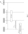
- FIG. 7 illustrates an exemplary procedure 700 for handling a failure in a backhaul link according to an embodiment of the present disclosure.
- the procedure in FIG. 7 may occur in response to a RLF on the backhaul link between two IAB nodes, for example, IAB nodes 2 and 3 in FIG. 2 .
- an upstream node may receive from a downstream node connected to the upstream node a signaling message indicating a failure in a backhaul link.
- IAB donor may receive a signaling message indicating a failure in a backhaul link between IAB nodes 2 and 3 from IAB node 3.
Landscapes
- Engineering & Computer Science (AREA)
- Computer Networks & Wireless Communication (AREA)
- Signal Processing (AREA)
- Computer Security & Cryptography (AREA)
- Mobile Radio Communication Systems (AREA)
- Monitoring And Testing Of Transmission In General (AREA)
Priority Applications (1)
| Application Number | Priority Date | Filing Date | Title |
|---|---|---|---|
| EP25176291.0A EP4580310A3 (de) | 2018-08-03 | 2018-08-03 | Verfahren und vorrichtung zur handhabung von funkverbindungsfehlern |
Applications Claiming Priority (3)
| Application Number | Priority Date | Filing Date | Title |
|---|---|---|---|
| EP25176291.0A EP4580310A3 (de) | 2018-08-03 | 2018-08-03 | Verfahren und vorrichtung zur handhabung von funkverbindungsfehlern |
| PCT/CN2018/098556 WO2020024269A1 (en) | 2018-08-03 | 2018-08-03 | Method and apparatus for handling radio link failure |
| EP18928749.3A EP3831117B1 (de) | 2018-08-03 | 2018-08-03 | Verfahren und vorrichtung zur handhabung von funkverbindungsausfällen |
Related Parent Applications (2)
| Application Number | Title | Priority Date | Filing Date |
|---|---|---|---|
| EP18928749.3A Division EP3831117B1 (de) | 2018-08-03 | 2018-08-03 | Verfahren und vorrichtung zur handhabung von funkverbindungsausfällen |
| EP18928749.3A Division-Into EP3831117B1 (de) | 2018-08-03 | 2018-08-03 | Verfahren und vorrichtung zur handhabung von funkverbindungsausfällen |
Publications (2)
| Publication Number | Publication Date |
|---|---|
| EP4580310A2 true EP4580310A2 (de) | 2025-07-02 |
| EP4580310A3 EP4580310A3 (de) | 2025-07-30 |
Family
ID=69232363
Family Applications (2)
| Application Number | Title | Priority Date | Filing Date |
|---|---|---|---|
| EP18928749.3A Active EP3831117B1 (de) | 2018-08-03 | 2018-08-03 | Verfahren und vorrichtung zur handhabung von funkverbindungsausfällen |
| EP25176291.0A Pending EP4580310A3 (de) | 2018-08-03 | 2018-08-03 | Verfahren und vorrichtung zur handhabung von funkverbindungsfehlern |
Family Applications Before (1)
| Application Number | Title | Priority Date | Filing Date |
|---|---|---|---|
| EP18928749.3A Active EP3831117B1 (de) | 2018-08-03 | 2018-08-03 | Verfahren und vorrichtung zur handhabung von funkverbindungsausfällen |
Country Status (5)
| Country | Link |
|---|---|
| US (2) | US12096503B2 (de) |
| EP (2) | EP3831117B1 (de) |
| CN (2) | CN112470508B (de) |
| ES (1) | ES3033811T3 (de) |
| WO (1) | WO2020024269A1 (de) |
Families Citing this family (13)
| Publication number | Priority date | Publication date | Assignee | Title |
|---|---|---|---|---|
| CN110830975A (zh) * | 2018-08-10 | 2020-02-21 | 索尼公司 | 电子装置、无线通信方法和计算机可读介质 |
| WO2020033965A1 (en) * | 2018-08-10 | 2020-02-13 | Kyungmin Park | Wireless backhaul link information |
| US11638319B2 (en) * | 2019-02-12 | 2023-04-25 | Samsung Electronics Co., Ltd. | Handling radio link failure in cellular mesh networks |
| CN113645010B (zh) * | 2019-02-14 | 2022-07-29 | 华为技术有限公司 | 触发无线链路失败的方法及设备 |
| US11291067B2 (en) * | 2019-03-01 | 2022-03-29 | At&T Intellectual Property I, L.P. | Detection of failure in a backhaul communications link |
| CN112312513B (zh) * | 2019-07-29 | 2021-12-03 | 华为技术有限公司 | 用于链路失败恢复的方法和装置 |
| JP7252367B2 (ja) * | 2019-11-07 | 2023-04-04 | 京セラ株式会社 | 通信制御方法及び無線中継装置 |
| WO2021162504A1 (ko) * | 2020-02-11 | 2021-08-19 | 엘지전자 주식회사 | 복수의 타이밍이 설정된 iab 노드의 통신 방법 및 장치 |
| CN115134865B (zh) * | 2021-03-25 | 2025-04-22 | 维沃移动通信有限公司 | 上行传输的控制方法、装置及终端 |
| CN116456375A (zh) * | 2022-01-06 | 2023-07-18 | 华为技术有限公司 | 通信方法和装置 |
| US20260046968A1 (en) * | 2022-08-09 | 2026-02-12 | Telefonaktiebolaget Lm Ericsson (Publ) | Network repeater devices and control methods |
| KR20240143235A (ko) * | 2023-03-23 | 2024-10-02 | 삼성전자주식회사 | 차세대 이동통신에서 빔 감지 실패로 인한 네트워크 제어 리피터의 동작 방법 및 장치 |
| KR20240146964A (ko) * | 2023-03-30 | 2024-10-08 | 삼성전자주식회사 | 무선 통신 시스템에서 네트워크 제어 중계기의 유휴/비활성화 상태에서 빔을 관리하는 방법 및 장치 |
Family Cites Families (7)
| Publication number | Priority date | Publication date | Assignee | Title |
|---|---|---|---|---|
| KR101759366B1 (ko) | 2010-02-11 | 2017-07-31 | 엘지전자 주식회사 | 기지국과 중계 노드 사이의 백홀 링크 실패를 복구하는 방법 및 장치 |
| WO2011112017A2 (en) * | 2010-03-11 | 2011-09-15 | Lg Electronics Inc. | Method for processing degradation of radio link quality in a wireless communication system supporting relays |
| CN102223658B (zh) * | 2010-04-19 | 2016-06-29 | 中兴通讯股份有限公司 | 一种处理无线链路失败的方法和中继节点 |
| EP2387270A1 (de) * | 2010-05-12 | 2011-11-16 | Nokia Siemens Networks Oy | Steuerung zur Wiederherstellung nach einer Funkverbindungsfehlfunktion in einem Kommunikationsnetz mit Relaisknoten |
| US12206480B2 (en) * | 2020-03-10 | 2025-01-21 | Lg Electronics Inc. | Method and device for assessing radio link quality in wireless communication system |
| US11889576B2 (en) * | 2020-08-14 | 2024-01-30 | Qualcomm Incorporated | Techniques for radio link management |
| US11728873B2 (en) * | 2021-07-09 | 2023-08-15 | Qualcomm Incorporated | Early beam failure detection |
-
2018
- 2018-08-03 CN CN201880095856.8A patent/CN112470508B/zh active Active
- 2018-08-03 CN CN202310768799.8A patent/CN116887319A/zh active Pending
- 2018-08-03 ES ES18928749T patent/ES3033811T3/es active Active
- 2018-08-03 EP EP18928749.3A patent/EP3831117B1/de active Active
- 2018-08-03 US US17/265,639 patent/US12096503B2/en active Active
- 2018-08-03 WO PCT/CN2018/098556 patent/WO2020024269A1/en not_active Ceased
- 2018-08-03 EP EP25176291.0A patent/EP4580310A3/de active Pending
-
2024
- 2024-08-19 US US18/808,484 patent/US20250126668A1/en active Pending
Also Published As
| Publication number | Publication date |
|---|---|
| CN116887319A (zh) | 2023-10-13 |
| US20250126668A1 (en) | 2025-04-17 |
| EP3831117A1 (de) | 2021-06-09 |
| CN112470508B (zh) | 2023-07-25 |
| WO2020024269A1 (en) | 2020-02-06 |
| EP3831117B1 (de) | 2025-06-25 |
| EP3831117C0 (de) | 2025-06-25 |
| EP3831117A4 (de) | 2022-03-02 |
| US12096503B2 (en) | 2024-09-17 |
| US20210315040A1 (en) | 2021-10-07 |
| ES3033811T3 (en) | 2025-08-08 |
| CN112470508A (zh) | 2021-03-09 |
| EP4580310A3 (de) | 2025-07-30 |
Similar Documents
| Publication | Publication Date | Title |
|---|---|---|
| US20250126668A1 (en) | Method and apparatus for handling radio link failure | |
| US12156082B2 (en) | Method and apparatus for reporting assistant information | |
| EP4221330B1 (de) | Verfahren und vorrichtung zur knotenauswahl und zugangssteuerung | |
| EP3818774B1 (de) | Verfahren und vorrichtung für backhaul-verbindungsumschaltung | |
| US12200797B2 (en) | Method and apparatus for transmitting radio link information | |
| WO2020056748A1 (en) | Method and apparatus for target integrated access and backhaul node selection | |
| US11792681B2 (en) | Method and apparatus for integrated access and backhaul node selection | |
| US12425905B2 (en) | Method and apparatus for reporting failure information in a communication system | |
| US12075328B2 (en) | Method and apparatus for reporting link assistant information and transmitting data |
Legal Events
| Date | Code | Title | Description |
|---|---|---|---|
| PUAI | Public reference made under article 153(3) epc to a published international application that has entered the european phase |
Free format text: ORIGINAL CODE: 0009012 |
|
| STAA | Information on the status of an ep patent application or granted ep patent |
Free format text: STATUS: THE APPLICATION HAS BEEN PUBLISHED |
|
| REG | Reference to a national code |
Ref country code: DE Ref legal event code: R079 Free format text: PREVIOUS MAIN CLASS: H04W0092140000 Ipc: H04W0024040000 |
|
| PUAL | Search report despatched |
Free format text: ORIGINAL CODE: 0009013 |
|
| AC | Divisional application: reference to earlier application |
Ref document number: 3831117 Country of ref document: EP Kind code of ref document: P |
|
| AK | Designated contracting states |
Kind code of ref document: A2 Designated state(s): AL AT BE BG CH CY CZ DE DK EE ES FI FR GB GR HR HU IE IS IT LI LT LU LV MC MK MT NL NO PL PT RO RS SE SI SK SM TR |
|
| AK | Designated contracting states |
Kind code of ref document: A3 Designated state(s): AL AT BE BG CH CY CZ DE DK EE ES FI FR GB GR HR HU IE IS IT LI LT LU LV MC MK MT NL NO PL PT RO RS SE SI SK SM TR |
|
| RIC1 | Information provided on ipc code assigned before grant |
Ipc: H04W 24/04 20090101AFI20250624BHEP Ipc: H04W 88/08 20090101ALI20250624BHEP Ipc: H04W 92/14 20090101ALI20250624BHEP |
|
| STAA | Information on the status of an ep patent application or granted ep patent |
Free format text: STATUS: REQUEST FOR EXAMINATION WAS MADE |