EP4580305A1 - Kommunikationsverfahren, basisstation und benutzervorrichtung - Google Patents
Kommunikationsverfahren, basisstation und benutzervorrichtung Download PDFInfo
- Publication number
- EP4580305A1 EP4580305A1 EP23872380.3A EP23872380A EP4580305A1 EP 4580305 A1 EP4580305 A1 EP 4580305A1 EP 23872380 A EP23872380 A EP 23872380A EP 4580305 A1 EP4580305 A1 EP 4580305A1
- Authority
- EP
- European Patent Office
- Prior art keywords
- multicast
- rrc
- user equipment
- multicast session
- inactive state
- Prior art date
- Legal status (The legal status is an assumption and is not a legal conclusion. Google has not performed a legal analysis and makes no representation as to the accuracy of the status listed.)
- Pending
Links
Images


Classifications
-
- H—ELECTRICITY
- H04—ELECTRIC COMMUNICATION TECHNIQUE
- H04W—WIRELESS COMMUNICATION NETWORKS
- H04W76/00—Connection management
- H04W76/20—Manipulation of established connections
- H04W76/27—Transitions between radio resource control [RRC] states
-
- H—ELECTRICITY
- H04—ELECTRIC COMMUNICATION TECHNIQUE
- H04W—WIRELESS COMMUNICATION NETWORKS
- H04W4/00—Services specially adapted for wireless communication networks; Facilities therefor
- H04W4/06—Selective distribution of broadcast services, e.g. multimedia broadcast multicast service [MBMS]; Services to user groups; One-way selective calling services
-
- H—ELECTRICITY
- H04—ELECTRIC COMMUNICATION TECHNIQUE
- H04W—WIRELESS COMMUNICATION NETWORKS
- H04W76/00—Connection management
- H04W76/40—Connection management for selective distribution or broadcast
Definitions
- the present disclosure relates to a communication method, a base station, and a user terminal used in a mobile communication system.
- the 3rd Generation Partnership Project (3GPP; registered trademark, the same applies below) has defined the technical specifications of New Radio (NR) that is a radio access technology of the fifth generation (5G).
- NR has features such as high speed, large capacity, high reliability, and low latency as compared to Long Term Evolution (LTE) that is a radio access technology of the fourth generation (4G).
- LTE Long Term Evolution
- 4G fourth generation
- the 3GPP has defined technical specifications of multicast/broadcast services (MBS) of 5G/NR (for example, see Non-Patent Document 1).
- MBS multicast/broadcast services
- Non-Patent Document 1 3GPP Technical Specification: TS 38.300 V17.1.0
- a network node is used in a mobile communication system that provides a multicast/broadcast service (MBS), the network node including: a transmitter that transmits multicast data, via a multicast session, to a user equipment in a radio resource control (RRC) connected state; a receiver that receives notification information for determining whether to cause the user equipment to perform reception of the multicast session in an RRC inactive state from another apparatus that is at least one of the user equipment or a core network apparatus; and a controller that determines whether to cause the user equipment to transition from the RRC connected state to the RRC inactive state based on the notification information.
- RRC radio resource control
- a user equipment is used in a mobile communication system that provides a multicast/broadcast service (MBS), the user equipment including: a receiver that receives multicast data from a network node via a multicast session when the user equipment is in a radio resource control (RRC) connected state; and a transmitter that transmits, to the network node, notification information for the network node to determine whether to cause the user equipment to perform reception of the multicast session in an RRC inactive state.
- MMS multicast/broadcast service
- RRC radio resource control
- the mobile communication system 1 includes User Equipment (UE) 100, a 5G radio access network (Next Generation Radio Access Network (NG-RAN)) 10, and a 5G Core Network (5GC) 20.
- UE User Equipment
- NG-RAN Next Generation Radio Access Network
- 5GC 5G Core Network
- the NG-RAN 10 may be hereinafter simply referred to as a RAN 10 (a network 10).
- the 5GC 20 may be simply referred to as a core network (CN) 20.
- CN core network
- the UE 100 is a mobile wireless communication apparatus.
- the UE 100 may be any apparatus as long as the UE 100 is used by a user.
- Examples of the UE 100 include a mobile phone terminal (including a smartphone) and/or a tablet terminal, a notebook PC, a communication module (including a communication card or a chipset), a sensor or an apparatus provided on a sensor, a vehicle or an apparatus provided on a vehicle (vehicle UE), and a flying object or an apparatus provided on a flying object (aerial UE).
- the NG-RAN 10 includes base stations (referred to as "gNBs" in the 5G system) 200.
- the gNBs 200 are interconnected via an Xn interface which is an inter-base station interface.
- Each gNB 200 manages one or more cells.
- the gNB 200 performs wireless communication with the UE 100 that has established a connection to the cell of the gNB 200.
- the gNB 200 has a radio resource management (RRM) function, a function of routing user data (hereinafter simply referred to as "data”), a measurement control function for mobility control and scheduling, and the like.
- RRM radio resource management
- the "cell” is used as a term representing a minimum unit of a wireless communication area.
- the "cell” is also used as a term representing a function or a resource for performing wireless communication with the UE 100.
- One cell belongs to one carrier frequency (hereinafter, simply referred to as a "frequency").
- the gNB can be connected to an Evolved Packet Core (EPC) corresponding to a core network of LTE.
- EPC Evolved Packet Core
- An LTE base station can also be connected to the 5GC.
- the LTE base station and the gNB can be connected via an inter-base station interface.
- the 5GC 20 includes an Access and Mobility Management Function (AMF) and a User Plane Function (UPF) 300.
- the AMF performs various types of mobility controls and the like for the UE 100.
- the AMF manages mobility of the UE 100 by communicating with the UE 100 by using Non-Access Stratum (NAS) signaling.
- NAS Non-Access Stratum
- the UPF controls data transfer.
- the AMF and UPF are connected to the gNB 200 via an NG interface which is an interface between a base station and the core network.
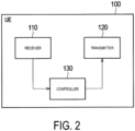
- the receiver 110 performs various types of reception under control of the controller 130.
- the receiver 110 includes an antenna and a reception device.
- the reception device converts a radio signal received through the antenna into a baseband signal (a reception signal) and outputs the resulting signal to the controller 130.
- the controller 130 performs various types of control and processing in the UE 100. Such processing includes processing of respective layers to be described later. The operations of the UE 100 described above and below may also be performed under the control of a controller 230.
- the controller 130 includes at least one processor and at least one memory.
- the memory stores a program to be executed by the processor and information to be used for processing by the processor.
- the processor may include a baseband processor and a Central Processing Unit (CPU).
- the baseband processor performs modulation and demodulation, coding and decoding, and the like of a baseband signal.
- the CPU executes the program stored in the memory to thereby perform various types of processing.
- FIG. 3 is a diagram illustrating a configuration of the gNB 200 (base station) according to an embodiment.
- the gNB 200 includes a transmitter 210, a receiver 220, a controller 230, and a backhaul communicator 240.
- the transmitter 210 and the receiver 220 constitute a wireless communicator that performs wireless communication with the UE 100.
- the backhaul communicator 240 constitutes a network communicator that performs communication with the CN 20.
- the receiver 220 performs various types of reception under control of the controller 230.
- the receiver 220 includes an antenna and a reception device.
- the reception device converts a radio signal received through the antenna into a baseband signal (a reception signal) and outputs the resulting signal to the controller 230.
- the controller 230 performs various types of control and processing in the gNB 200. Such processing includes processing of respective layers to be described later. The operations of the gNB 200 described above and below may also be performed under the control of the controller 230.
- the controller 230 includes at least one processor and at least one memory.
- the memory stores a program to be executed by the processor and information to be used for processing by the processor.
- the processor may include a baseband processor and a CPU.
- the baseband processor performs modulation and demodulation, coding and decoding, and the like of a baseband signal.
- the CPU executes the program stored in the memory to thereby perform various types of processing.
- the backhaul communicator 240 is connected to a neighboring base station via an Xn interface which is an inter-base station interface.
- the backhaul communicator 240 is connected to the AMF/UPF 300 via an NG interface between a base station and the core network.
- the gNB 200 may include a Central Unit (CU) and a Distributed Unit (DU) (i.e., functions are divided), and both units may be connected via an F1 interface that is a fronthaul interface.
- CU Central Unit
- DU Distributed Unit
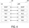
- FIG. 4 is a diagram illustrating a configuration of a protocol stack of a radio interface of a user plane handling data.
- a radio interface protocol of the user plane includes a PHYsical (PHY) layer, a Medium Access Control (MAC) layer, a Radio Link Control (RLC) layer, a Packet Data Convergence Protocol (PDCP) layer, and a Service Data Adaptation Protocol (SDAP) layer.
- PHY PHYsical
- MAC Medium Access Control
- RLC Radio Link Control
- PDCP Packet Data Convergence Protocol
- SDAP Service Data Adaptation Protocol
- the RLC layer transmits data to the RLC layer on the reception side by using functions of the MAC layer and the PHY layer. Data and control information are transmitted between the RLC layer of the UE 100 and the RLC layer of the gNB 200 via a logical channel.
- the PDCP layer performs header compression/decompression, encryption/decryption, and the like.
- the SDAP layer performs mapping between an IP flow as the unit of Quality of Service (QoS) control performed by a core network and a radio bearer as the unit of QoS control performed by an Access Stratum (AS). Note that, when the RAN is connected to the EPC, the SDAP need not be provided.
- QoS Quality of Service
- AS Access Stratum
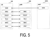
- FIG. 5 is a diagram illustrating a configuration of a protocol stack of a radio interface of a control plane handling signaling (a control signal).
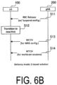
- Main logical channels used for MBS delivery are a multicast traffic channel (MTCH), a dedicated traffic channel (DTCH), and a multicast control channel (MCCH).
- the MTCH is a PTM downlink channel for transmitting MBS data of either a multicast session or a broadcast session from the network 10 to the UE 100.
- the DTCH is a PTP channel for transmitting MBS data of a multicast session from the network 10 to the UE 100.
- the MCCH is a PTM downlink channel for transmitting MBS broadcast control information associated with one or more MTCHs from the network 10 to the UE 100.
- the UE 100 in the RRC idle state, the RRC inactive state, or the RRC connected state receives an MBS configuration for a broadcast session (e.g., parameters required for MTCH reception) via the MCCH.
- MBS configuration e.g., parameters required for MTCH reception
- Parameters required for reception of the MCCH (MCCH configuration) are provided through system information.
- system information block type 20 SIB 20
- SIB 21 includes information related to service continuity of MBS broadcast reception.
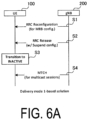
- a solution based on the delivery mode 1 shown in FIG. 6(a) and a solution based on the delivery mode 2 shown in FIG. 6(b) are considered.
- step S3 the UE 100 transitions from the RRC connected state to the RRC inactive (INACTIVE) state in response to receiving the RRC Release message in step S2.
- step S4 the UE 100 in the RRC inactive state continues using the multicast configuration of step S1 to receive the multicast data on the MTCH through the multicast sessions.
- multicast configuration may be performed using an RRC Release message.
- Both the RRC Reconfiguration message and the RRC Release message are RRC messages transmitted per UE on the dedicated control channel (DCCH), and are hereinafter also referred to as dedicated RRC messages.
- DCCH dedicated control channel
- the gNB 200 transmits an RRC Release message for causing the UE 100 to transition to the RRC inactive state to the UE 100 in the RRC connected state.
- the RRC Release message includes a configuration (Suspend Config.) for the RRC inactive state.
- step S12 the UE 100 transitions to the RRC inactive (INACTIVE) state in response to receiving the RRC Release message in step S11.
- a UE 100 that performs a group call application such as Push to Talk (PTT) is also present.
- PTT Push to Talk
- Such a UE 100 may perform uplink (UL) transmission of a multicast session while performing multicast reception of a multicast session on downlink (DL). If such a UE 100 is caused to transition to the RRC inactive state, the UE 100 needs to transition to the RRC connected state every time the UE 100 performs UL transmission, which is rather inefficient.
- the gNB 200 is enabled to appropriately determine whether to cause the UE 100 that performs multicast reception in the RRC connected state to transition to the RRC inactive state, and to realize efficient multicast reception.
- the gNB 200 which transmits multicast data to a UE 100 in an RRC connected state via a multicast session, receives notification information for determining whether to cause the UE 100 to perform reception of the multicast session in an RRC inactive state from another apparatus that is at least one of the UE 100 or a core network apparatus.
- the core network apparatus may be a UPF or the like.
- the gNB 200 determines whether to cause the UE 100 to transition from the RRC connected state to the RRC inactive state.
- the notification information may be information based on a UL traffic characteristics parameter of the multicast session.
- the UE 100 when there is no UL transmission or the frequency of UL transmission is low, the UE 100 does not need to frequently transition to the RRC connected state even if the UE 100 tries to receive the multicast session in the RRC inactive state, and thus the gNB 200 determines to cause the UE 100 to transition to the RRC inactive state.
- the UE 100 or AMF 300A specifies the UL traffic characteristics parameters of the multicast session.
- the UE 100 or the AMF 300A transmits information indicating whether the UE 100 can perform reception of the multicast session in the RRC inactive state to the gNB 200 as notification information based on the UL traffic characteristics parameters.
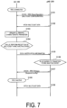
- FIG. 7 is a diagram illustrating an operation example of the mobile communication system 1 according to the embodiment. Prior to the present operation, it is assumed that the UE 100 has joined a multicast session. It is assumed that the UE 100 is performing or will perform multicast reception in the RRC connected state.
- step S101 the gNB 200 transmits a multicast configuration necessary for reception of a multicast session (that is, multicast reception) to the UE 100 in the RRC connected state in a dedicated RRC message (in the illustrated example, an RRC Reconfiguration message).
- the UE 100 receives the multicast configuration in the dedicated RRC message.
- a configuration may include a configuration for allowing or requesting the UE 100 to transmit notification information described below.
- the UE 100 specifies a UL traffic characteristics parameter for the multicast session.
- the UL traffic characteristics parameter includes at least one selected from the group consisting of a parameter indicating the presence or absence of UL transmission of the multicast session, a parameter indicating the occurrence probability per unit time or the occurrence frequency of UL transmission of the multicast session, an allowable delay parameter of UL transmission of the multicast session, and a parameter indicating an uplink transmission data size of the multicast session.
- step S105 the UE 100 transmits an RRC message including notification information indicating the determination result of step S104 to the gNB 200.
- the UE 100 may transmit an RRC message including the notification information indicating the determination result to the gNB 200 based on the determination of step S104 that the UE 100 can perform multicast reception in the RRC inactive state.
- the gNB 200 receives the RRC message. That is, the UE 100 may notify the gNB 200 that the UE 100 can receive the multicast session in the RRC inactive state.
- the RRC message may include MBS session information associated with the notification information.
- the MBS session information is information for identifying the multicast session (multicast service), which is, for example, a TMGI.
- the RRC message may be an MBS Interest Indication message.
- the MBS Interest Indication message includes an MBS-ServiceList (in particular, a list of TMGIs), which is a list of MBS broadcast services that the UE 100 is receiving or wishes to receive.
- the MBS-ServiceList may be a list of MBS broadcast services and MBS multicast services that the UE 100 is receiving or wishes to receive.
- the UE Assistance Information message may be able to include additional information indicating that multicast reception will be continued in association with the TMGI of the MBS multicast service.
- the MBS Interest Indication message may be able to include, as a new information element, a TMGI indicating a multicast session that can be received in the RRC inactive state.
- step S108 the UE 100 transitions to the RRC inactive state from the RRC connected state upon reception of the RRC Release message in step S107.
- step S109 the UE 100 having transitioned to the RRC inactive state receives the multicast data on the MTCH via the multicast session based on the multicast configuration configured in step S101 or S107.
- the UE 100 may receive the multicast data on the MTCH through the multicast session based on the multicast configuration transmitted on the MCCH from the gNB 200.
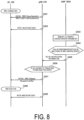
- Steps S201 and S202 are the same as or similar to those of the operation of FIG. 7 .
- the UE 100 or the AMF 300A specifies a UL traffic characteristics parameter of a multicast session and transmits the UL traffic characteristics parameter to the gNB 200 as notification information. That is, in the present modification, more detailed information (material for determination) than that in the above-described embodiment is given to the gNB 200 as notification information. Differences from the operation of the above-described embodiment will be described below, and overlapping description will be omitted.
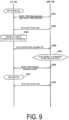
- Steps S301 and S302 are the same as or similar to those of the embodiment described above.
- step S304 the UE 100 transmits an RRC message including the UL traffic characteristics parameter specified in step S303 as notification information to the gNB 200.
- the RRC message may include MBS session information associated with the notification information.
- the RRC message may be a UE Assistance Information message or an MBS Interest Indication message.
Landscapes
- Engineering & Computer Science (AREA)
- Computer Networks & Wireless Communication (AREA)
- Signal Processing (AREA)
- Multimedia (AREA)
- Mobile Radio Communication Systems (AREA)
Applications Claiming Priority (2)
| Application Number | Priority Date | Filing Date | Title |
|---|---|---|---|
| JP2022155369 | 2022-09-28 | ||
| PCT/JP2023/035055 WO2024071158A1 (ja) | 2022-09-28 | 2023-09-27 | 通信方法、基地局、及びユーザ装置 |
Publications (2)
| Publication Number | Publication Date |
|---|---|
| EP4580305A1 true EP4580305A1 (de) | 2025-07-02 |
| EP4580305A4 EP4580305A4 (de) | 2025-10-15 |
Family
ID=90477881
Family Applications (1)
| Application Number | Title | Priority Date | Filing Date |
|---|---|---|---|
| EP23872380.3A Pending EP4580305A4 (de) | 2022-09-28 | 2023-09-27 | Kommunikationsverfahren, basisstation und benutzervorrichtung |
Country Status (5)
| Country | Link |
|---|---|
| US (1) | US20250227804A1 (de) |
| EP (1) | EP4580305A4 (de) |
| JP (1) | JP7795646B2 (de) |
| CN (1) | CN120266575A (de) |
| WO (1) | WO2024071158A1 (de) |
Family Cites Families (2)
| Publication number | Priority date | Publication date | Assignee | Title |
|---|---|---|---|---|
| JP7584645B2 (ja) * | 2020-10-23 | 2024-11-15 | テレフオンアクチーボラゲット エルエム エリクソン(パブル) | 通信ネットワークにおけるネットワークノード、デバイスおよび方法 |
| JP7602416B2 (ja) | 2021-03-30 | 2024-12-18 | 旭有機材株式会社 | 難燃性発泡体用組成物 |
-
2023
- 2023-09-27 JP JP2024550368A patent/JP7795646B2/ja active Active
- 2023-09-27 WO PCT/JP2023/035055 patent/WO2024071158A1/ja not_active Ceased
- 2023-09-27 CN CN202380081452.4A patent/CN120266575A/zh active Pending
- 2023-09-27 EP EP23872380.3A patent/EP4580305A4/de active Pending
-
2025
- 2025-03-28 US US19/093,515 patent/US20250227804A1/en active Pending
Also Published As
| Publication number | Publication date |
|---|---|
| JPWO2024071158A1 (de) | 2024-04-04 |
| US20250227804A1 (en) | 2025-07-10 |
| EP4580305A4 (de) | 2025-10-15 |
| CN120266575A (zh) | 2025-07-04 |
| WO2024071158A1 (ja) | 2024-04-04 |
| JP7795646B2 (ja) | 2026-01-07 |
Similar Documents
| Publication | Publication Date | Title |
|---|---|---|
| US20240080939A1 (en) | Communication control method and user equipment | |
| US20230262533A1 (en) | Communication control method | |
| US20240080940A1 (en) | Communication control method | |
| US20230261970A1 (en) | Communication control method | |
| EP4142402A1 (de) | Kommunikationssteuerungsverfahren und benutzergerät | |
| US20240373508A1 (en) | Communication method and user equipment | |
| US12574992B2 (en) | Communication control method and user equipment utilizing an inactivity timer for multicast broadcast service | |
| US20230254668A1 (en) | Communication control method | |
| US20250227811A1 (en) | Communication method | |
| US20250184167A1 (en) | Communication method | |
| US20240373509A1 (en) | Communication method | |
| US20240298381A1 (en) | Communication method | |
| US20240032073A1 (en) | Communication control method and base station | |
| US20240032148A1 (en) | Communication control method and user equipment | |
| EP4580305A1 (de) | Kommunikationsverfahren, basisstation und benutzervorrichtung | |
| US20250220773A1 (en) | Communication method and user equipment | |
| US20250331056A1 (en) | Communication method and network apparatus | |
| US20240397407A1 (en) | Communication method and user equipment | |
| US20250358899A1 (en) | Communication method | |
| US20260067980A1 (en) | Communication method, user equipment, and network node | |
| EP4679917A1 (de) | Kommunikationsverfahren | |
| US20260032763A1 (en) | Communication method, user equipment, non-transitory computer-readable medium, chipset and system | |
| US20240284555A1 (en) | Communication method and user equipment |
Legal Events
| Date | Code | Title | Description |
|---|---|---|---|
| STAA | Information on the status of an ep patent application or granted ep patent |
Free format text: STATUS: THE INTERNATIONAL PUBLICATION HAS BEEN MADE |
|
| PUAI | Public reference made under article 153(3) epc to a published international application that has entered the european phase |
Free format text: ORIGINAL CODE: 0009012 |
|
| STAA | Information on the status of an ep patent application or granted ep patent |
Free format text: STATUS: REQUEST FOR EXAMINATION WAS MADE |
|
| 17P | Request for examination filed |
Effective date: 20250326 |
|
| AK | Designated contracting states |
Kind code of ref document: A1 Designated state(s): AL AT BE BG CH CY CZ DE DK EE ES FI FR GB GR HR HU IE IS IT LI LT LU LV MC ME MK MT NL NO PL PT RO RS SE SI SK SM TR |
|
| A4 | Supplementary search report drawn up and despatched |
Effective date: 20250912 |
|
| RIC1 | Information provided on ipc code assigned before grant |
Ipc: H04W 76/27 20180101AFI20250908BHEP Ipc: H04W 4/06 20090101ALI20250908BHEP Ipc: H04W 48/06 20090101ALI20250908BHEP Ipc: H04W 76/10 20180101ALI20250908BHEP |
|
| DAV | Request for validation of the european patent (deleted) | ||
| DAX | Request for extension of the european patent (deleted) |