EP4580281A1 - Strahlverwaltungsverfahren - Google Patents
Strahlverwaltungsverfahren Download PDFInfo
- Publication number
- EP4580281A1 EP4580281A1 EP23862483.7A EP23862483A EP4580281A1 EP 4580281 A1 EP4580281 A1 EP 4580281A1 EP 23862483 A EP23862483 A EP 23862483A EP 4580281 A1 EP4580281 A1 EP 4580281A1
- Authority
- EP
- European Patent Office
- Prior art keywords
- prediction model
- input
- adaptation layer
- pattern
- prediction result
- Prior art date
- Legal status (The legal status is an assumption and is not a legal conclusion. Google has not performed a legal analysis and makes no representation as to the accuracy of the status listed.)
- Pending
Links
Images


Classifications
-
- H—ELECTRICITY
- H04—ELECTRIC COMMUNICATION TECHNIQUE
- H04L—TRANSMISSION OF DIGITAL INFORMATION, e.g. TELEGRAPHIC COMMUNICATION
- H04L5/00—Arrangements affording multiple use of the transmission path
- H04L5/0001—Arrangements for dividing the transmission path
- H04L5/0014—Three-dimensional division
- H04L5/0023—Time-frequency-space
-
- H—ELECTRICITY
- H04—ELECTRIC COMMUNICATION TECHNIQUE
- H04W—WIRELESS COMMUNICATION NETWORKS
- H04W72/00—Local resource management
- H04W72/04—Wireless resource allocation
- H04W72/044—Wireless resource allocation based on the type of the allocated resource
- H04W72/046—Wireless resource allocation based on the type of the allocated resource the resource being in the space domain, e.g. beams
-
- G—PHYSICS
- G06—COMPUTING OR CALCULATING; COUNTING
- G06N—COMPUTING ARRANGEMENTS BASED ON SPECIFIC COMPUTATIONAL MODELS
- G06N20/00—Machine learning
-
- G—PHYSICS
- G06—COMPUTING OR CALCULATING; COUNTING
- G06N—COMPUTING ARRANGEMENTS BASED ON SPECIFIC COMPUTATIONAL MODELS
- G06N3/00—Computing arrangements based on biological models
- G06N3/02—Neural networks
- G06N3/04—Architecture, e.g. interconnection topology
- G06N3/0495—Quantised networks; Sparse networks; Compressed networks
-
- G—PHYSICS
- G06—COMPUTING OR CALCULATING; COUNTING
- G06N—COMPUTING ARRANGEMENTS BASED ON SPECIFIC COMPUTATIONAL MODELS
- G06N3/00—Computing arrangements based on biological models
- G06N3/02—Neural networks
- G06N3/08—Learning methods
-
- H—ELECTRICITY
- H04—ELECTRIC COMMUNICATION TECHNIQUE
- H04B—TRANSMISSION
- H04B17/00—Monitoring; Testing
- H04B17/30—Monitoring; Testing of propagation channels
- H04B17/309—Measuring or estimating channel quality parameters
- H04B17/318—Received signal strength
-
- H—ELECTRICITY
- H04—ELECTRIC COMMUNICATION TECHNIQUE
- H04B—TRANSMISSION
- H04B17/00—Monitoring; Testing
- H04B17/30—Monitoring; Testing of propagation channels
- H04B17/373—Predicting channel quality or other radio frequency [RF] parameters
-
- H—ELECTRICITY
- H04—ELECTRIC COMMUNICATION TECHNIQUE
- H04B—TRANSMISSION
- H04B7/00—Radio transmission systems, i.e. using radiation field
- H04B7/02—Diversity systems; Multi-antenna system, i.e. transmission or reception using multiple antennas
- H04B7/04—Diversity systems; Multi-antenna system, i.e. transmission or reception using multiple antennas using two or more spaced independent antennas
- H04B7/06—Diversity systems; Multi-antenna system, i.e. transmission or reception using multiple antennas using two or more spaced independent antennas at the transmitting station
- H04B7/0686—Hybrid systems, i.e. switching and simultaneous transmission
- H04B7/0695—Hybrid systems, i.e. switching and simultaneous transmission using beam selection
- H04B7/06952—Selecting one or more beams from a plurality of beams, e.g. beam training, management or sweeping
-
- H—ELECTRICITY
- H04—ELECTRIC COMMUNICATION TECHNIQUE
- H04B—TRANSMISSION
- H04B7/00—Radio transmission systems, i.e. using radiation field
- H04B7/02—Diversity systems; Multi-antenna system, i.e. transmission or reception using multiple antennas
- H04B7/04—Diversity systems; Multi-antenna system, i.e. transmission or reception using multiple antennas using two or more spaced independent antennas
- H04B7/08—Diversity systems; Multi-antenna system, i.e. transmission or reception using multiple antennas using two or more spaced independent antennas at the receiving station
- H04B7/0868—Hybrid systems, i.e. switching and combining
- H04B7/088—Hybrid systems, i.e. switching and combining using beam selection
-
- H—ELECTRICITY
- H04—ELECTRIC COMMUNICATION TECHNIQUE
- H04L—TRANSMISSION OF DIGITAL INFORMATION, e.g. TELEGRAPHIC COMMUNICATION
- H04L5/00—Arrangements affording multiple use of the transmission path
- H04L5/003—Arrangements for allocating sub-channels of the transmission path
- H04L5/0048—Allocation of pilot signals, i.e. of signals known to the receiver
- H04L5/0051—Allocation of pilot signals, i.e. of signals known to the receiver of dedicated pilots, i.e. pilots destined for a single user or terminal
-
- H—ELECTRICITY
- H04—ELECTRIC COMMUNICATION TECHNIQUE
- H04W—WIRELESS COMMUNICATION NETWORKS
- H04W24/00—Supervisory, monitoring or testing arrangements
- H04W24/08—Testing, supervising or monitoring using real traffic
-
- H—ELECTRICITY
- H04—ELECTRIC COMMUNICATION TECHNIQUE
- H04W—WIRELESS COMMUNICATION NETWORKS
- H04W24/00—Supervisory, monitoring or testing arrangements
- H04W24/10—Scheduling measurement reports ; Arrangements for measurement reports
Definitions
- This application relates to the field of communication technologies, and in particular, to a beam management method and an apparatus.
- a wireless communication network for example, in a mobile communication network, services supported by the network are increasingly diversified, and therefore, requirements that need to be met are increasingly diversified.
- the network needs to be capable of supporting ultra-high rates, ultra-low latency, and/or ultra-large connections.
- This feature makes network planning, network configuration, and/or resource scheduling increasingly complex.
- the network has increasingly powerful functions, for example, supports an increasingly high spectrum and new technologies such as a high-order multiple-input multiple-output (multiple-input multiple-output, MIMO) technology, beamforming, and/or beam management, network energy saving becomes a hot research topic.
- MIMO multiple-input multiple-output
- This disclosure provides a beam management method and an apparatus, to reduce overheads in a beam management process.
- a beam management method may be implemented at a reference signal receiver.
- the method may be performed by a terminal device, an access network device, a module (for example, a DU or a near-real-time RIC) of the access network device, or a non-real-time RIC.
- a module for example, a DU or a near-real-time RIC of the access network device, or a non-real-time RIC.
- the method includes: mapping a reference signal measurement quantity to input adaptation information by using an input adaptation layer, where a beam pattern corresponding to the reference signal measurement quantity is a first beam pattern; and obtaining a first beam prediction result by using a beam prediction model, where an input of the beam prediction model includes the input adaptation information, the input of the beam prediction model matches a second beam pattern, and the first beam pattern is different from the second beam pattern.
- the method includes: obtaining a first beam prediction result by using a beam prediction model, where an input of the beam prediction model includes a reference signal measurement quantity, and a beam pattern corresponding to the reference signal measurement quantity is a second beam pattern; and mapping the first beam prediction result to a second beam prediction result by using an output adaptation layer.
- the method includes: mapping a reference signal measurement quantity to input adaptation information by using an input adaptation layer, where a beam pattern corresponding to the reference signal measurement quantity is a first beam pattern; obtaining a first beam prediction result by using a beam prediction model, where an input of the beam prediction model includes the input adaptation information, the input of the beam prediction model matches a second beam pattern, and the first beam pattern is different from the second beam pattern; and mapping the first beam prediction result to a second beam prediction result by using an output adaptation layer.
- a small quantity of beam prediction models and an input adaptation layer and/or an output adaptation layer whose scale is less than that of the beam prediction model may be set for beam management, without setting one beam prediction model for each sparse beam pattern.
- storage overheads of the beam prediction model may be reduced.
- signaling overheads may be further reduced.
- the first beam prediction result includes Top-K1 beams in a full beam corresponding to the first beam pattern or the second beam pattern, where K1 is a positive integer.
- the second beam prediction result includes Top-K2 beams in the full beam corresponding to the first beam pattern or the second beam pattern, where K2 is a positive integer.
- a top beam in the full beam may be predicted by sweeping the sparse beam pattern and using the beam prediction model, without obtaining the top beam in the full beam by sweeping the full beam, so that latency overheads and reference signal overheads in a beam management process can be reduced.
- the information about the beam prediction model is received.
- the beam prediction model may be flexibly configured.
- the beam prediction model is included in a candidate beam prediction model set, each beam prediction model in the candidate beam prediction model set corresponds to one beam pattern, and the beam prediction model corresponds to the second beam pattern.
- information about each beam prediction model in the candidate beam prediction model set is agreed on in a protocol or received from a transmitter.
- a correspondence between a beam prediction model in the candidate beam prediction model set and a (sparse) beam pattern is agreed on in a protocol or received from a transmitter.
- information indicating the second beam pattern is received. According to the method, signaling overheads for configuring the beam prediction model may be reduced.
- the input adaptation layer and/or the output adaptation layer may be flexibly configured.
- the input adaptation layer or the output adaptation layer is obtained through training.
- an ideal beam prediction result is obtained based on a measurement quantity corresponding to a full beam.
- a measurement quantity corresponding to a sparse beam of the first beam pattern is mapped to the input adaptation information by using the input adaptation layer.
- An actual beam prediction result is obtained based on the input adaptation information and the beam prediction model.
- a parameter of the input adaptation layer is adjusted based on the ideal beam prediction result and the actual beam prediction result, to enable a difference between the ideal beam prediction result and the actual beam prediction result to be less than a threshold.
- an ideal beam prediction result is obtained based on a measurement quantity corresponding to a full beam.
- An actual beam prediction result is obtained based on measurement of a sparse beam of the second beam pattern, the beam prediction model, and the output adaptation layer.
- a parameter of the output adaptation layer is adjusted based on the ideal beam prediction result and the actual beam prediction result, to enable a difference between the ideal beam prediction result and the actual beam prediction result to be less than a threshold.
- an ideal beam prediction result is obtained based on a measurement quantity corresponding to a full beam.
- a measurement quantity corresponding to a sparse beam of the first beam pattern is mapped to the input adaptation information by using the input adaptation layer.
- An actual beam prediction result is obtained based on the input adaptation information, the beam prediction model, and the output adaptation layer.
- At least one of a parameter of the input adaptation layer and a parameter of the output adaptation layer is adjusted based on the ideal beam prediction result and the actual beam prediction result, to enable a difference between the ideal beam prediction result and the actual beam prediction result to be less than a threshold.
- the input adaptation layer and/or the output adaptation layer may be flexibly adjusted based on a channel condition, so that the input adaptation layer and/or the output adaptation layer better match/matches the current channel condition, and matching performance is better.
- a beam management method may be implemented at a reference signal transmitter.
- the method may be performed by a terminal device, an access network device, a module (for example, a DU or a near-real-time RIC) of the access network device, or a non-real-time RIC.
- a module for example, a DU or a near-real-time RIC of the access network device, or a non-real-time RIC.
- the method includes: sending information about an input adaptation layer.
- the input adaptation layer is configured to perform adaptation on a reference signal measurement quantity to obtain an input of a beam prediction model, a beam pattern corresponding to the reference signal measurement quantity is a first beam pattern, the input of the beam prediction model matches a second beam pattern, and the first beam pattern is different from the second beam pattern.
- the method includes: sending information about an output adaptation layer.
- the output adaptation layer is configured to map a first beam prediction result output by a beam prediction model to a second beam prediction result, and the first beam prediction result is different from the second beam prediction result.
- the method includes: sending information about an input adaptation layer and information about an output adaptation layer.
- the input adaptation layer is configured to perform adaptation on a reference signal measurement quantity to obtain an input of a beam prediction model, a beam pattern corresponding to the reference signal measurement quantity is a first beam pattern, the input of the beam prediction model matches a second beam pattern, and the first beam pattern is different from the second beam pattern.
- the output adaptation layer is configured to map a first beam prediction result output by the beam prediction model to a second beam prediction result, and the first beam prediction result is different from the second beam prediction result.
- the method further includes: indicating the beam prediction model from a candidate beam prediction model set.
- Each beam prediction model in the candidate beam prediction model set corresponds to one beam pattern.
- information about each beam prediction model in the candidate beam prediction model set is agreed on in a protocol, or the method includes: sending information about each beam prediction model in the candidate beam prediction model set.
- a correspondence between a beam prediction model in the candidate beam prediction model set and a (sparse) beam pattern is agreed on in a protocol, or the method includes: sending a correspondence between a beam prediction model in the candidate beam prediction model set and a (sparse) beam pattern.
- the method includes: sending information indicating the second beam pattern.
- a communication apparatus may implement the method according to the first aspect.
- the apparatus may include modules that are in one-to-one correspondence with the methods/operations/steps/actions described in the first aspect.
- the modules may be implemented through a hardware circuit, software, or a combination of a hardware circuit and software.
- the communication apparatus includes a baseband apparatus and a radio frequency apparatus.
- the communication apparatus includes a processing unit (also referred to as a processing module sometimes) and a transceiver unit (also referred to as a transceiver module sometimes).
- the transceiver unit can implement a sending function and a receiving function. When the transceiver unit implements the sending function, the transceiver unit may be referred to as a sending unit (also referred to as a sending module sometimes).
- the transceiver unit When the transceiver unit implements the receiving function, the transceiver unit may be referred to as a receiving unit (also referred to as a receiving module sometimes).
- the sending unit and the receiving unit may be a same functional module, the functional module is referred to as a transceiver unit, and the functional module can implement the sending function and the receiving function.
- the sending unit and the receiving unit may be different functional modules, and the transceiver unit is a general term for these functional modules.
- the processing unit is configured to: map a reference signal measurement quantity to input adaptation information by using an input adaptation layer, where a beam pattern corresponding to the reference signal measurement quantity is a first beam pattern; and obtain a first beam prediction result by using a beam prediction model, where an input of the beam prediction model includes the input adaptation information, the input of the beam prediction model matches a second beam pattern, and the first beam pattern is different from the second beam pattern.
- a reference signal is received by the receiving unit.
- the processing unit is configured to: obtain a first beam prediction result by using a beam prediction model, where an input of the beam prediction model includes a reference signal measurement quantity, and a beam pattern corresponding to the reference signal measurement quantity is a second beam pattern; and map the first beam prediction result to a second beam prediction result by using an output adaptation layer.
- a reference signal is received by the receiving unit.
- the processing unit is configured to: map a reference signal measurement quantity to input adaptation information by using an input adaptation layer, where a beam pattern corresponding to the reference signal measurement quantity is a first beam pattern; obtain a first beam prediction result by using a beam prediction model, where an input of the beam prediction model includes the input adaptation information, the input of the beam prediction model matches a second beam pattern, and the first beam pattern is different from the second beam pattern; and map the first beam prediction result to a second beam prediction result by using an output adaptation layer.
- the receiving unit is configured to receive information about the beam prediction model.
- the beam prediction model is included in a candidate beam prediction model set, each beam prediction model in the candidate beam prediction model set corresponds to one beam pattern, and the beam prediction model corresponds to the second beam pattern.
- information about each beam prediction model in the candidate beam prediction model set is agreed on in a protocol or received from a transmitter by the receiving unit.
- a correspondence between a beam prediction model in the candidate beam prediction model set and a (sparse) beam pattern is agreed on in a protocol or received from a transmitter by the receiving unit.
- the receiving unit is configured to receive information indicating the second beam pattern.
- the receiving unit is configured to receive information about the input adaptation layer or information about the output adaptation layer.
- the processing unit is configured to obtain the input adaptation layer or the output adaptation layer through training.
- the processing unit is configured to obtain the input adaptation layer or the output adaptation layer through training.
- the communication apparatus includes a processor, configured to implement the method described in the first aspect.
- the apparatus may further include a memory, configured to store instructions and/or data.
- the memory is coupled to the processor.
- the processor can implement the method described in the first aspect.
- the apparatus may further include a communication interface, and the communication interface is used by the apparatus to communicate with another device.
- the communication interface may be a transceiver, a circuit, a bus, a module, a pin, or another type of communication interface, and the another device may be a model inference node or the like.
- a function of the processor is similar to that of the foregoing processing unit, and a function of the communication interface is similar to that of the foregoing transceiver unit. Details are not described herein again.
- a communication apparatus may implement the method according to the second aspect.
- the apparatus may include modules that are in one-to-one correspondence with the methods/operations/steps/actions described in the second aspect.
- the modules may be implemented through a hardware circuit, software, or a combination of a hardware circuit and software.
- the communication apparatus includes a baseband apparatus, or includes a baseband apparatus and a radio frequency apparatus.
- the communication apparatus includes a processing unit (also referred to as a processing module sometimes) and a transceiver unit (also referred to as a transceiver module sometimes).
- the transceiver unit can implement a sending function and a receiving function.
- the transceiver unit When the transceiver unit implements the sending function, the transceiver unit may be referred to as a sending unit (also referred to as a sending module sometimes). When the transceiver unit implements the receiving function, the transceiver unit may be referred to as a receiving unit (also referred to as a receiving module sometimes).
- the sending unit and the receiving unit may be a same functional module, the functional module is referred to as a transceiver unit, and the functional module can implement the sending function and the receiving function.
- the sending unit and the receiving unit may be different functional modules, and the transceiver unit is a general term for these functional modules.
- the sending unit is configured to send information about an input adaptation layer.
- the input adaptation layer is configured to perform adaptation on a reference signal measurement quantity to obtain an input of a beam prediction model, a beam pattern corresponding to the reference signal measurement quantity is a first beam pattern, the input of the beam prediction model matches a second beam pattern, and the first beam pattern is different from the second beam pattern.
- the information about the input adaptation layer is determined by the processing unit.
- the sending unit is configured to send information about an output adaptation layer.
- the output adaptation layer is configured to map a first beam prediction result output by a beam prediction model to a second beam prediction result, and the first beam prediction result is different from the second beam prediction result.
- the information about the output adaptation layer is determined by the processing unit.
- the sending unit is configured to send information about an input adaptation layer and information about an output adaptation layer.
- the input adaptation layer is configured to perform adaptation on a reference signal measurement quantity to obtain an input of a beam prediction model, a beam pattern corresponding to the reference signal measurement quantity is a first beam pattern, the input of the beam prediction model matches a second beam pattern, and the first beam pattern is different from the second beam pattern.
- the output adaptation layer is configured to map a first beam prediction result output by the beam prediction model to a second beam prediction result, and the first beam prediction result is different from the second beam prediction result.
- the information about the input adaptation layer and the information about the output adaptation layer are determined by the processing unit.
- the sending unit is further configured to indicate the beam prediction model from a candidate beam prediction model set.
- Each beam prediction model in the candidate beam prediction model set corresponds to one beam pattern.
- information about each beam prediction model in the candidate beam prediction model set is agreed on in a protocol, or the sending unit is further configured to send information about each beam prediction model in the candidate beam prediction model set.
- a correspondence between a beam prediction model in the candidate beam prediction model set and a (sparse) beam pattern is agreed on in a protocol, or the sending unit is further configured to send a correspondence between a beam prediction model in the candidate beam prediction model set and a (sparse) beam pattern.
- the sending unit is further configured to send information indicating the second beam pattern.
- the communication apparatus includes a processor, configured to implement the method described in the second aspect.
- the apparatus may further include a memory, configured to store instructions and/or data.
- the memory is coupled to the processor.
- the processor can implement the method described in the second aspect.
- the apparatus may further include a communication interface, and the communication interface is used by the apparatus to communicate with another device.
- the communication interface may be a transceiver, a circuit, a bus, a module, a pin, or another type of communication interface, and the another device may be a model inference node or the like.
- a function of the processor is similar to that of the foregoing processing unit, and a function of the communication interface is similar to that of the foregoing transceiver unit. Details are not described herein again.
- a computer-readable storage medium includes instructions. When the instructions are run on a computer, the computer is enabled to perform the method in either the first aspect or the second aspect.
- a chip system includes a processor, may further include a memory, and is configured to implement the method in either the first aspect or the second aspect.
- the chip system may include a chip, or may include a chip and another discrete component.
- a computer program product includes instructions. When the instructions are run on a computer, the computer is enabled to perform the method in either the first aspect or the second aspect.
- a communication system includes the apparatus in the third aspect and the apparatus in the fourth aspect.
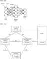
- FIG. 1 is a diagram of an architecture of a communication system 1000 to which this disclosure is applicable.
- the communication system includes a radio access network (radio access network, RAN) 100 and a core network (core network, CN) 200.
- the communication system 1000 may further include an internet 300.
- the radio access network 100 may include at least one access network device (for example, 110a and 110b in FIG. 1 ), and may further include at least one terminal device (for example, 120a to 120j in FIG. 1 ).
- the terminal device is connected to the access network device in a wireless manner.
- the access network device is connected to the core network in a wireless or wired manner.
- a core network device and the access network device may be different physical devices that are independent of each other, or functions of the core network device and logical functions of the access network device may be integrated into a same physical device, or a part of the functions of the core network device and a part of the functions of the access network device may be integrated into one physical device. Physical existence forms of the core network device and the access network device are not limited in this disclosure.
- the terminal devices may be connected to each other in a wireless manner.
- the access network devices may be connected to each other in a wired or wireless manner.
- FIG. 1 is merely a diagram, and is not intended to limit this disclosure.
- the communication system may further include another network device, for example, may further include a wireless relay device and a wireless backhaul device.
- the access network device may be a base station (base station), an evolved NodeB (evolved NodeB, eNodeB), a transmission reception point (transmission reception point, TRP), a next generation NodeB (next generation NodeB, gNB) in a 5th generation (5th generation, 5G) mobile communication system, an access network device in an open radio access network (open radio access network, O-RAN), a next generation NodeB in a 6th generation (6th generation, 6G) mobile communication system, a base station in a future mobile communication system, an access node in a wireless fidelity (wireless fidelity, Wi-Fi) system, or the like.
- 5G may also be referred to as new radio (new radio, NR).
- the access network device may be a module or a unit that completes a part of functions of a base station.
- the access network device may be a central unit (central unit, CU), a distributed unit (distributed unit, DU), a central unit control plane (CU control plane, CU-CP) module, or a central unit user plane (CU user plane, CU-UP) module.
- the access network device may be a macro base station (for example, 110a in FIG. 1 ), may be a micro base station or an indoor base station (for example, 110b in FIG. 1 ), or may be a relay node, a donor node, or the like.
- a specific technology and a specific device form that are used by the access network device are not limited in this disclosure.
- an apparatus configured to implement the function of the access network device may be the access network device, or may be an apparatus that can support the access network device in implementing the function, for example, a chip system, a hardware circuit, a software module, or a combination of a hardware circuit and a software module.
- the apparatus may be mounted in the access network device or used together with the access network device.
- the chip system may include a chip, or may include a chip and another discrete component.
- the protocol layer structure may include a control plane protocol layer structure and a user plane protocol layer structure.
- the control plane protocol layer structure may include at least one of the following: a radio resource control (radio resource control, RRC) layer, a packet data convergence protocol (packet data convergence protocol, PDCP) layer, a radio link control (radio link control, RLC) layer, a media access control (media access control, MAC) layer, or a physical (physical, PHY) layer.
- the user plane protocol layer structure may include at least one of the following: a service data adaptation protocol (service data adaptation protocol, SDAP) layer, a PDCP layer, an RLC layer, a MAC layer, and a physical layer.
- the protocol layer structure between the access network device and the terminal device may be considered as an access stratum (access stratum, AS) structure.
- a non-access stratum non-access stratum, NAS
- the access network device may forward the information between the terminal device and the core network device through transparent transmission.
- a NAS message may be mapped to or included in RRC signaling as an element of the RRC signaling.
- the protocol layer structure between the access network device and the terminal device may further include an artificial intelligence (artificial intelligence, AI) layer used for transmission of data related to an AI function.
- AI artificial intelligence
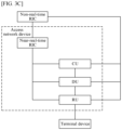
- the access network device may include a CU and a DU. This design may be referred to as CU and DU split. A plurality of DUs may be controlled by one CU in a centralized manner. For example, an interface between the CU and the DU is referred to as an F1 interface.
- a control plane (control plane, CP) interface may be F1-C
- a user plane (user plane, UP) interface may be F1-U. Specific names of the interfaces are not limited in this disclosure.
- the CU and the DU may be divided according to a protocol layer of a wireless network.
- functions of a PDCP layer and a protocol layer above the PDCP layer are set in the CU, and functions of a protocol layer below the PDCP layer (for example, an RLC layer, a MAC layer, and a PHY layer) are set in the DU.
- functions of the protocol layer above the PDCP layer are set in the CU, and functions of the PDCP layer and the protocol layer below the PDCP layer are set in the DU. This is not limited.
- a radio unit (radio unit, RU) of the DU may be disposed remotely.
- the RU has a radio frequency function.
- the DU and the RU may be divided at the PHY layer.
- the DU may implement higher-layer functions of the PHY layer, and the RU may implement lower-layer functions of the PHY layer.
- functions of the PHY layer may include at least one of the following: adding a cyclic redundancy check (cyclic redundancy check, CRC) bit, channel encoding, rate matching, scrambling, modulation, layer mapping, precoding, resource mapping, physical antenna mapping, or radio frequency sending.
- CRC cyclic redundancy check
- the higher-layer functions of the PHY layer may include adding a CRC bit, channel encoding, rate matching, scrambling, modulation, and layer mapping
- the lower-layer functions of the PHY layer may include precoding, resource mapping, physical antenna mapping, and radio frequency sending.
- the higher-layer functions of the PHY layer may include adding a CRC bit, channel encoding, rate matching, scrambling, modulation, layer mapping, and precoding
- the lower-layer functions of the PHY layer may include resource mapping, physical antenna mapping, and radio frequency sending.
- the functions of the CU may be further divided, and a control plane and a user plane are split and implemented by using different entities.
- Split entities are respectively a control plane CU entity (namely, a CU-CP entity) and a user plane CU entity (namely, a CU-UP entity).
- the CU-CP entity and the CU-UP entity may be separately connected to the DU.
- an entity may be understood as a module or a unit, and may exist in a form of a hardware structure, a software module, or a combination of a hardware structure and a software module. This is not limited.
- any one of the CU, the CU-CP, the CU-UP, the DU, and the RU may be a software module, a hardware structure, or a combination of a software module and a hardware structure.
- the CU, the CU-CP, the CU-UP, and the DU are software modules
- the RU is a hardware structure.
- all possible combination forms are not enumerated herein.
- the modules and methods performed by the modules also fall within the protection scope of this disclosure.
- the method in this disclosure when the method in this disclosure is performed by the access network device, the method may be specifically performed by at least one of the CU, the CU-CP, the CU-UP, the DU, the RU, or a near-real-time RIC described below.
- the function of the access network device when the function of the access network device is completed by a module of the access network device, for example, when the DU sends a signal like a reference signal to the terminal device, it may be understood as that a destination of the signal is the terminal device.
- the sending is logically performed, and the reference signal is not limited to being physically sent by the DU directly to the terminal device.
- a module A sends information to the terminal includes: The module A sends the information to the terminal through an air interface.
- the module A may perform a baseband operation and/or an intermediate radio frequency operation on the information.
- the module A delivers the information to a module B, and the module B sends the information to the terminal.
- the module B may transparently transmit the information, segment the information and then send the information, or multiplex the information and other information and then send the information.
- the module B may perform a baseband operation and/or an intermediate radio frequency operation on the information and then send the information.
- the module B may encapsulate the information in a data packet.
- the module B may further add a packet header and/or a padding bit to the data packet.
- the function of the access network device when the function of the access network device is completed by a module of the access network device, for example, when the DU receives a signal like a reference signal from the terminal device, it may be understood as that a source of the signal is the terminal device.
- the transmission is logically performed, and the reference signal is not limited to being physically sent by the terminal device directly to the DU.
- receiving information from the terminal device may be understood as that a source of the information is the terminal device.
- a module A receives information from the terminal device includes: The module A receives the information from the terminal through an air interface.
- the module A may perform a baseband operation and/or an intermediate radio frequency operation on the information.
- a module B receives the information from the terminal through an air interface, and delivers the information to the module A. That the module B delivers the information to the module A includes: The module B transparently delivers the received information to the module A, combines a plurality of received segments into the information and then delivers the information to the module A, or extracts the information from multiplexing information and then delivers the information to the module A.
- the module B may perform a baseband operation and/or an intermediate radio frequency operation on the received information and then send the information.
- the information received by the module B is encapsulated in a data packet.
- the data packet includes a packet header and/or a padding bit, and the like.
- the foregoing module A or B may be one module or may be a plurality of modules that are sequentially coupled. This is not limited.
- the module A is a DU module
- the module B is an RU module.
- the module A is a CU-CP module
- the module B is a DU module and an RU module.
- the terminal device may be a mobile phone, a tablet computer, a computer with a wireless transceiver function, a wearable device, a vehicle, an uncrewed aerial vehicle, a helicopter, an airplane, a ship, a robot, a robot arm, a smart home device, or the like.
- a specific technology and a specific device form that are used by the terminal device are not limited in this disclosure.
- an apparatus configured to implement a function of the terminal device may be a terminal device, or may be an apparatus that can support the terminal device in implementing the function, for example, a chip system, a hardware circuit, a software module, or a hardware circuit combined with a software module.
- the apparatus may be mounted in the terminal device or may be used together with the terminal device.
- the apparatus configured to implement the function of the terminal device is the terminal device.
- the access network device and/or the terminal device may be at a fixed location or may be movable.
- the access network device and/or the terminal device may be deployed on land, including indoor or outdoor, in a handheld manner or vehicle-mounted manner, may be deployed on water, or may be deployed on an airplane, a balloon, and an artificial satellite in air.
- Application scenarios of the access network device and the terminal device are not limited in this disclosure.
- the access network device and the terminal device may be deployed in a same scenario or different scenarios. For example, the access network device and the terminal device are both deployed on the land. Alternatively, the access network device is deployed on the land and the terminal device is deployed on the water. Examples are not provided one by one.
- Roles of the access network device and the terminal device may be relative.
- the helicopter or uncrewed aerial vehicle 120i in FIG. 1 may be configured as a mobile access network device.
- the terminal device 120i For the terminal devices 120j that access the radio access network 100 via 120i, the terminal device 120i is an access network device.
- the base station 110a 120i is a terminal device.
- 110a and 120i communicate with each other according to a wireless air interface protocol.
- 110a and 120i may alternatively communicate with each other according to an interface protocol between base stations.
- relative to 110a, 120i is also an access network device. Therefore, both the access network device and the terminal device may be collectively referred to as communication apparatuses.
- 110a and 110b in FIG. 1 may be referred to as communication apparatuses having the function of the access network device
- 120a to 120j in FIG. 1 may be referred to as communication apparatuses having the function of the terminal device.
- a high-frequency band for example, a millimeter wave (millimeter wave, mmW) frequency band
- a transmitter may improve signal transmission quality by using a beamforming technology.
- artificial intelligence artificial intelligence, AI is introduced into the beamforming technology.
- the artificial intelligence enables machines to have human intelligence.
- machines can use computer software and hardware to simulate some intelligent human behaviors.
- a machine learning method may be used.
- a machine obtains a model through learning (or training) by using training data.
- the model represents mapping from input to output.
- the model obtained through learning may be used for inference (or prediction).
- the model may be used to predict an output corresponding to a given input.
- the output may also be referred to as an inference result.
- Machine learning may include supervised learning, unsupervised learning, and reinforcement learning.
- a mapping relationship between the sample values and the sample labels is learned by using a machine learning algorithm, and the learned mapping relationship is expressed by using an AI model.
- a process of training the machine learning model is a process of learning the mapping relationship.
- a sample value is input into the model to obtain a predicted value of the model, and a model parameter is optimized by calculating an error between the predicted value of the model and a sample label (ideal value).
- a new sample label may be predicted by using the learned mapping relationship.
- the mapping relationship learned through the supervised learning may include linear mapping or non-linear mapping. Learning tasks may be classified into a classification task and a regression task based on types of labels.
- a sample is used as a supervised signal, in other words, a model learns a mapping relationship between samples, which is referred to as self-supervised learning.
- a model parameter is optimized by calculating an error between a predicted value of the model and the sample.
- the self-supervised learning may be used for signal compression and decompression restoration. Common algorithms include an autoencoder, a generative adversarial network, and the like.
- the reinforcement learning is different from the supervised learning, and is an algorithm that learns a policy of resolving problems by interacting with an environment. Different from the supervised learning and the unsupervised learning, the reinforcement learning does not have clear "correct" action label data.
- the algorithm needs to interact with the environment to obtain a reward signal fed back by the environment and adjust a decision action to obtain a larger reward signal value.
- a reinforcement learning model adjusts a downlink transmit power of each user based on a total system throughput fed back by a wireless network, to expect to obtain a higher system throughput.
- a goal of the reinforcement learning is also to learn a mapping relationship between an environment status and an optimal decision action.
- a label of "correct action" cannot be obtained in advance. Therefore, a network cannot be optimized by calculating an error between an action and the "correct action”.
- Reinforcement learning training is implemented through iterative interaction with the environment.
- a neural network (neural network, NN) is a specific model in a machine learning technology. According to a universal approximation theorem, the neural network can theoretically approximate any continuous function, so that the neural network has a capability of learning any mapping. In a conventional communication system, rich expertise is required to design a communication module. However, in a neural network-based deep learning communication system, an implicit pattern structure may be automatically discovered from a large quantity of data sets and a mapping relationship between data may be established, to obtain performance better than that of a conventional modeling method.
- n is a positive integer
- w i and x i may be various possible types such as a decimal, an integer (for example, 0, a positive integer, or a negative integer), or a complex number.
- w i is used as a weight of x i , and is used to weight x i .
- An offset for performing weighted summation on the input values based on the weights is, for example, b. There may be a plurality of forms of the activation function.
- b may be any possible type like a decimal, an integer (for example, 0, a positive integer, or a negative integer), or a complex number.
- Activation functions of different neurons in the neural network may be the same or different.
- the neural network includes an input layer, a hidden layer, and an output layer.
- the input layer of the neural network performs neuron processing on received input information, and transfers a processing result to an intermediate hidden layer.
- the hidden layer performs calculation on the received processing result to obtain a calculation result.
- the hidden layer transfers the calculation result to the output layer or a next adjacent hidden layer.
- the output layer obtains an output result of the neural network.
- One neural network may include one hidden layer, or include a plurality of hidden layers that are sequentially connected. This is not limited.
- the neural network in this disclosure is, for example, a deep neural network (deep neural network, DNN).
- the DNN may include a feedforward neural network (feedforward neural network, FNN), a convolutional neural network (convolutional neural network, CNN), and a recurrent neural network (recurrent neural network, RNN).
- feedforward neural network feedforward neural network
- CNN convolutional neural network
- RNN recurrent neural network
- FIG. 2B shows an FNN network.
- the CNN is a neural network dedicated to processing data of a similar grid structure. For example, both time series data (timeline discrete sampling) and image data (two-dimensional discrete sampling) may be considered as the data of the similar grid structure.
- the CNN performs a convolution operation by capturing partial information through a window with a fixed size rather than performing an operation by using all input information at one time, which greatly reduces a calculation amount of a model parameter.
- different convolution kernel operations may be used for each window, so that the CNN can better extract a feature of input data.
- the RNN is a DNN network using feedback time series information. Inputs of the RNN include a new input value at a current moment and an output value of the RNN at a previous moment.
- the RNN is suitable for obtaining a sequence feature having a time correlation, and is especially suitable for applications such as speech recognition and channel encoding and decoding.
- a loss function may be defined in a model training process.
- the loss function describes a gap or a difference between an output value of the model and an ideal target value.
- a specific form of the loss function is not limited in this disclosure.
- the model training process may be considered as the following process: A part of or all parameters of the model are adjusted, so that a value of the loss function is less than a threshold or meets a target requirement.
- the model may also be referred to as an AI model, a rule, or another name. This is not limited.
- An AI model may be considered as a specific method for implementing an AI function.
- the AI model represents a mapping relationship or a function between an input and an output of the model.
- the AI function may include at least one of the following: data collection, model training (or model learning), model information release, model deduction (or referred to as model inference, inference, prediction, or the like), model monitoring or model verification, inference result release, or the like.
- the AI function may also be referred to as an AI (related) operation or an AI-related function.
- an independent network element (for example, referred to as an AI network element, an AI node, or an AI device) may be introduced into the communication system shown in FIG. 1 , to implement a part of or all AI-related operations.
- the AI network element may be directly connected to the access network device, or may be indirectly connected to the access network device through a third-party network element.
- the third-party network element may be a core network element.
- an AI entity may be configured or disposed in another network element in the communication system, to implement an AI-related operation.
- the AI entity may also be referred to as an AI module, an AI unit, or another name, and is mainly configured to implement a part or all AI functions.
- a specific name of the AI entity is not limited in this disclosure.
- the OAM is configured to operate, administer, and/or maintain a core network device (a network management system of the core network device), and/or is configured to operate, administer, and/or maintain an access network device (a network management system of the access network device).
- this disclosure includes first OAM and second OAM, where the first OAM is a network management system of a core network device, and the second OAM is a network management system of an access network device.
- the first OAM and/or the second OAM include/includes an AI entity.
- this disclosure includes third OAM, and the third OAM is a network management system of both a core network device and an access network device.
- the third OAM includes an AI entity.
- FIG. 3A to FIG. 3D are example diagrams of application frameworks of AI in a communication system.
- an AI model is deployed in at least one of a core network device, an access network device, a terminal, or OAM, and a corresponding function is implemented by using the AI model.
- AI models deployed in different nodes may be the same or different.
- the models are different in at least one of the following: a structure parameter of the model (for example, at least one of a quantity of neural network layers, a neural network width, a connection relationship between layers, a weight of a neuron, an activation function of the neuron, or an offset in an activation function), an input parameter of the model (for example, a type of the input parameter and/or a dimension of the input parameter), or an output parameter of the model (for example, a type of the output parameter and/or a dimension of the output parameter).
- a structure parameter of the model for example, at least one of a quantity of neural network layers, a neural network width, a connection relationship between layers, a weight of a neuron, an activation function of the neuron, or an offset in an activation function
- an input parameter of the model for example, a type of the input parameter and/or a dimension of the input parameter
- an output parameter of the model for example, a type of the output parameter and/or a dimension of the output parameter.
- N noise
- X is a transmit signal
- W is a transmitter precoding matrix.
- a signal obtained by precoding X by using W is W*X.
- W*X is a final transmit signal of the transmitter.
- W*X has a beamforming effect in space.
- a signal that arrives at the receiver after channel propagation is H*W*X.
- V is a receiver precoding matrix.
- a signal obtained by precoding H*W*X by using V is V*H*W*X.
- V*H*W*X+N is a final receive signal of the receiver, and V*H*W*X has a beamforming effect in space.
- a data form of a precoding matrix is usually a complex number, and another data form is not excluded in this disclosure.
- the precoding matrix may also be referred to as a codebook, and one precoding matrix corresponds to one codebook.
- a process of determining W and/or V in a multi-beam system may be referred to as a beam management process, or it is described as that a process of determining a beam corresponding to W and/or a beam corresponding to V may be referred to as a beam management process.
- the transmitter has T candidate beams in total, in other words, the transmitter has T candidate precoding matrices W in total, respectively denoted as W i , where a value of i ranges from 0 to T-1; and the receiver has R candidate beams in total, in other words, the receiver has R candidate precoding matrices V, respectively denoted as V j , where a value of j ranges from 0 to R-1.
- the transmitter and the receiver are relative to the reference signal.
- names of the receiver and the transmitter may be interchanged.
- a type of the reference signal is not limited.
- a value of the reference signal is notified in advance to the receiver, so that the reference signal can be measured.
- the value of the reference signal is agreed on in a protocol, or is notified in advance by the receiver to the transmitter. This is not limited.
- the reference signal is a demodulation reference signal (demodulation reference signal, DMRS) of a physical downlink control channel (physical downlink control channel, PDCCH), a DMRS of a physical downlink shared channel (physical downlink shared channel, PDSCH), a channel state information reference signal (channel state information reference signal, CSI-RS), a synchronization signal (for example, a primary synchronization signal (primary synchronization signal, PSS) and/or a secondary synchronization signal (secondary synchronization signal, SSS)), a DMRS of a synchronization signal, a phase tracking reference signal (phase tracking reference signal, PTRS), or another possible downlink signal.
- DMRS demodulation reference signal
- PDCCH physical downlink control channel
- DMRS of a physical downlink shared channel physical downlink shared channel
- CSI-RS channel state information reference signal
- CSI-RS channel state information reference signal
- a synchronization signal for example, a primary synchronization signal (primary synchronization
- the reference signal is a DMRS of a physical uplink shared channel (physical uplink shared channel, PUSCH), a DMRS of a physical uplink control channel (physical uplink control channel, PUCCH), a random access preamble (preamble), a sounding reference signal (sounding reference signal, SRS), or another possible uplink signal.
- PUSCH physical uplink shared channel
- PUCCH physical uplink control channel
- preamble random access preamble
- SRS sounding reference signal
- any receiver beamformed beam may form a transmit-receive beam pair with the transmitter beamformed beam. Therefore, a process of determining a top transmit-receive beam pair may be split into: performing receiver beam sweeping for a transmitter beam to determine a top receiver beam that matches the transmitter beam. Then, this process may be repeated for each of the remaining T-1 transmitter beams, to determine a global top transmit-receive beam pair. Similarly, for each receiver beam, any transmitter beam may form a transmit-receive beam pair with the receiver beam. Therefore, a process of determining a top transmit-receive beam pair may be split into: performing transmitter beam sweeping for a receiver beam to determine a top transmitter beam that matches the receiver beam.
- this process may be repeated for each of the remaining R-1 receiver beams, to determine a global top transmit-receive beam pair.
- a principle of the receiver beam sweeping is similar to that of the transmitter beam sweeping, a beam management method provided in this disclosure may be described in this specification by using the transmitter beam sweeping as an example.
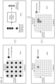
- S401 A transmitter sweeps a sparse beam by using a sparse beam pattern.
- the transmitter sweeps 16 of the beams in total.
- the 16 beams are equivalent to some sparse beams in the full beam.
- a horizontal direction and a vertical direction are used to present a spatial direction of each beam.
- beam division may be based on a two-dimensional plane direction, may be based on a three-dimensional space direction, or may be based on another possible manner. This is not limited.
- the transmitter performs beam polling in a time division manner by using each beam in the 16 beams displayed in black boxes.
- the transmitter separately performs beamforming on reference signals by using 16 precoding matrices corresponding to the 16 beams, and sends beamformed reference signals to a receiver in a time division manner.
- the receiver receives the reference signals by using the sparse beam pattern, and performs beam prediction.
- the receiver receives the reference signals corresponding to the 16 beams, and may obtain 16 measurement quantities in total.
- the 16 measurement quantities are referred to as measurement quantities corresponding to the sparse beam pattern in S401.
- the receiver inputs the 16 measurement quantities into a beam prediction model, and obtains Top-K (Top-K) beams in the full beam through inference. In other words, the receiver obtains indexes of the Top-K beams in the full beam including the 64 beams through prediction.
- the receiver may send, to the transmitter, the indexes of the K beams or indexes of K precoding matrices corresponding to the K beams.
- the transmitter may communicate with the receiver by using any one beam in the K beams.
- the transmitter may further determine a top beam from the K beams by using S403 and S404.
- codebooks precoding matrices
- S404 The receiver determines the top beam.
- the receiver receives three reference signals obtained through beamforming performed by using the Top-3 beams, and may obtain three measurement quantities in total.
- the receiver may determine a top measurement quantity in the three measurement quantities.
- a beam corresponding to the top measurement quantity is the top beam.
- the receiver may send an index of the top beam or an index of a precoding matrix corresponding to the top beam to the transmitter.
- Top-3 beams are a beam 0, a beam 1, and a beam 2.
- the access network device sweeps the three beams, and the terminal device may learn, through measurement, that a top beam is the beam 1.
- the transmitter and the receiver may perform data channel transmission by using the beam.
- the access network device may send downlink data to the terminal device by using the top beam, for example, send a PDSCH; and/or the access network device may receive downlink data from the terminal device by using the top beam, for example, receive a PUSCH.
- sending data of a data channel by using a beam may be understood as precoding the data by using a precoding matrix corresponding to the beam.
- Performance of the foregoing beam prediction model during inference is related to a sparse beam pattern used when the beam prediction model is trained. For example, when the beam prediction model is trained, an input of the beam prediction model is determined by using a measurement quantity corresponding to a sparse beam pattern 1, so that a difference between Top-K results output by the beam prediction model and Top-K results obtained through full beam sweeping is less than a threshold. In this case, when inference is performed by using the beam prediction model obtained through training, a measurement quantity corresponding to a sparse beam pattern 2 may be input into the beam prediction model. In this case, the sparse beam pattern 2 does not correspond to or does not match the beam prediction model.
- the sparse beam pattern 1 indicates that eight beams are swept, and the sparse beam pattern 2 indicates that 16 beams are swept.
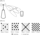
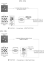
- FIG. 6 shows four different sparse beam patterns of a full beam including 64 beams.
- a full beam pattern is different or a system supports a plurality of full beam patterns, for example, when the full beam pattern includes 128 beams or the system supports a full beam pattern including 64 beams and a full beam pattern including 128 beams, there are more sparse beam patterns. Therefore, to meet an actual application requirement, one beam prediction model may need to be configured for each sparse beam pattern. In this case, a receiver needs to consume a large quantity of storage resources to store a plurality of beam prediction models, or needs to consume a large quantity of air interface resources to exchange the plurality of beam prediction models with a transmitter.
- this disclosure proposes a beam management method.
- the method can reduce a quantity of beam prediction models in the system.
- an input adaptation layer or referred to as an input adaptation model
- an output adaptation layer or referred to as an output adaptation model
- the beam prediction model may be referred to as a reference beam prediction model or a basic beam prediction model.
- the small quantity is not limited.
- the small quantity may be 2, 3, 5, 6, 8, or another possible value. This is not limited.
- Scenario 1 A sparse beam pattern matches a beam prediction model.
- a transmitter sends a reference signal by using a pattern A, and sweeps 16 beams in the pattern A in a time division manner.
- a receiver obtains indexes of Top-K1 beams in a full beam through prediction based on a reference signal measurement quantity and the beam prediction model.
- the sparse beam pattern matching the beam prediction model in FIG. 7 is the pattern A, and an output matching the beam prediction model is indexes of Top-5 beams in the full beam.
- Scenario 2 A sparse beam pattern (an input format) does not match a beam prediction model.
- a method corresponding to Scenario 2 may be described as: A receiver maps a reference signal measurement quantity to input adaptation information by using an input adaptation layer, where a beam pattern corresponding to the reference signal measurement quantity is a first beam pattern, the adaptation information corresponds to a second beam pattern, and the first beam pattern is different from the second beam pattern. The receiver obtains a first beam prediction result by using the beam prediction model, where an input of the beam prediction model includes the adaptation information.
- a method corresponding to Scenario 2 may be described as: A receiver maps a reference signal measurement quantity to input adaptation information by using an input adaptation layer, where a beam pattern corresponding to the reference signal measurement quantity is a first beam pattern. The receiver obtains a first beam prediction result by using the beam prediction model, where an input of the beam prediction model includes the adaptation information, the input of the beam prediction model matches a second beam pattern, and the first beam pattern is different from the second beam pattern.
- the input of the model includes one or more features, for example, the input of the beam prediction model includes the reference signal measurement quantity or the input adaptation information, that the input of the model may further include another feature is not excluded.
- a transmitter sends a reference signal by using a pattern B.
- a pattern A matches the beam prediction model. Therefore, after obtaining the reference signal measurement quantity corresponding to the pattern B, the transmitter maps the reference signal measurement quantity to the input adaptation information by using the input adaptation layer.
- the transmitter inputs the input adaptation information into the beam prediction model, and outputs indexes of Top-K1 beams in a full beam.
- Scenario 3 An output format does not match a beam prediction model.
- a method corresponding to Scenario 3 may be described as: A receiver inputs a reference signal measurement quantity into the beam prediction model, to obtain a first beam prediction result. The receiver maps the first beam prediction result to a second beam prediction result by using an output adaptation layer.
- a beam prediction result required in Scenario 3 is indexes of Top-K2 beams, for example, indexes of Top-5 beams.
- a beam prediction result matching the beam prediction model is indexes of Top-K1 beams, for example, indexes of Top-3 beams. Therefore, after obtaining the indexes of the Top-5 beams through inference by using the beam prediction model, a transmitter maps the indexes of the Top-5 beams to the indexes of the Top-3 beams by using the output adaptation layer.
- Scenario 4 A sparse beam pattern (an input format) and an output format do not match a beam prediction model.
- Scenario 4 may be understood as a combination of Scenario 2 and Scenario 3.
- a method corresponding to Scenario 4 may be described as:
- a receiver maps a reference signal measurement quantity to input adaptation information by using an input adaptation layer, where a beam pattern corresponding to the reference signal measurement quantity is a first beam pattern, the adaptation information corresponds to a second beam pattern, and the first beam pattern is different from the second beam pattern.
- the receiver obtains a first beam prediction result by using the beam prediction model, where an input of the beam prediction model includes the adaptation information.
- the receiver maps the first beam prediction result to a second beam prediction result by using an output adaptation layer.
- a receiver maps a reference signal measurement quantity to input adaptation information by using an input adaptation layer, where a beam pattern corresponding to the reference signal measurement quantity is a first beam pattern.
- the receiver obtains a first beam prediction result by using the beam prediction model, where an input of the beam prediction model includes the adaptation information, the input of the beam prediction model matches a second beam pattern, and the first beam pattern is different from the second beam pattern.
- the receiver maps the first beam prediction result to a second beam prediction result by using an output adaptation layer.
- the input adaptation layer is mainly configured to map the reference signal measurement quantity to being in an input format that matches the beam prediction model.
- a name of the input adaptation layer is not limited in this disclosure.
- the input adaptation layer may also be referred to as an input adaptation model, a first model, or another name.
- a structure of the input adaptation layer is not limited in this disclosure.
- the structure of the input adaptation layer is a neural network.
- the input adaptation layer includes at least one of the following: one or more fully connected layers, one or more CNN layers, or one or more RNN layers.
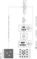
- FIG. 8 shows a possible structure of an input adaptation layer.
- an input dimension of the input adaptation layer may be represented as [ N in , N sc ], and an output dimension of the input adaptation layer may be represented as [ N out , N sc ] , where N in is a quantity of beamformed beams in a sparse beam pattern before mapping, N out is a quantity of beamformed beams in a sparse beam pattern matching a beam prediction model, and N sc is a quantity of resources occupied by a reference signal, for example, a quantity of subcarriers or a quantity of resource elements (resource elements, REs).
- N in , N out , and N sc are positive integers. Values of N in and N out may be the same.
- N in and N out respectively correspond to a pattern 1 and a pattern 2 shown in FIG. 6 .
- values of N in and N out may be different.
- N in and N out respectively correspond to a pattern 3 shown in FIG. 6 and the pattern A shown in FIG. 7 .
- the input adaptation layer may perform adaptation by performing a downsampling operation.
- the beam prediction model predicts a beam prediction result mainly based on a reference signal measurement quantity.
- the following uses an example in which the beam prediction result is a top beam in a full beam for description.
- full beam patterns may be the same, or may be different. This is not limited.
- the full beam patterns are cell-level information, the full beam patterns are the same for the different terminal devices in the cell.
- the full beam patterns are terminal device-level information or terminal device group-level information
- the full beam patterns may be different for the different terminal devices in the cell.
- the beam prediction model in this disclosure may further predict another type of result, and a principle is similar.
- the beam prediction model may predict a top beam in a beam subset of a full beam, a top beam subset of a full beam, a beam whose corresponding measurement quantity is lower than a threshold in a full beam or a subset of the full beam, or a beam whose corresponding measurement quantity is higher than a threshold in a full beam or a subset of the full beam.
- a name of the beam prediction model is not limited in this disclosure.
- the beam prediction model may also be referred to as a second model or another name.
- an output adaptation layer is mainly configured to map a first beam prediction result to a second beam prediction result, for example, map indexes of Top-K1 beams to indexes of Top-K2 beams.
- K1 and K2 are positive integers, and values of K1 and K2 are different.
- a name of the output adaptation layer is not limited in this disclosure.
- the output adaptation layer may also be referred to as an output adaptation model, a third model, or another name.
- a structure of the output adaptation layer is not limited in this disclosure.
- the structure of the output adaptation layer is a neural network.
- the output adaptation layer includes at least one of the following: one or more fully connected layers, one or more CNN layers, or one or more RNN layers.
- An input of the output adaptation layer is a first beam prediction result, for example, indexes of Top-K1 beams
- an output of the output adaptation layer is a second beam prediction result, for example, indexes of Top-K2 beams.
- FIG. 10 shows a specific beam prediction procedure according to this disclosure.
- the procedure is described by using an example in which a transmitter is an access network device and a receiver is a terminal device.
- a quantity of antennas or antenna ports on a network side is far greater than that on a terminal side
- a quantity of beamformed beams on the network side is also far greater than a quantity of beams on the terminal side.
- potential overheads and latency brought by performing sparse beam sweeping on the network side are reduced to a greater extent.
- the transmitter may alternatively be a terminal device, and the receiver is an access network device, to perform beam management on a terminal device side.
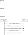
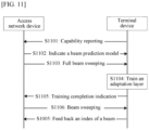
- the terminal device reports capability information to the access network device.
- the terminal device may report the capability information to the access network device based on a query request of the access network device, or may actively report the capability information to the access network device when accessing a network. Specific time or a specific trigger event for reporting the capability information by the terminal device is not limited in this disclosure.
- the terminal device may report at least one of the following capability information to the access network device:
- the access network device may configure an AI model for the terminal device, to run a method in this disclosure.
- the access network device may configure an appropriate AI model for the terminal device based on the machine learning model type supported by the terminal device, the size of the memory space used to store the machine learning model, the computing power information, the hardware information, and the like.
- the access network device may learn of the existing beam prediction model on the terminal device side, and/or may determine whether a new beam prediction model needs to be further configured for the terminal device, and the like.
- S1001 is an optional step. For example, when a capability of the terminal device is agreed on in a protocol, the terminal device does not need to report the capability by using S1001. Alternatively, when the terminal device has previously reported a capability to the access network device and information about the capability is relatively fixed, in a specific beam prediction process, the terminal device may not need to report the capability again by using S1001.
- the access network device sends information about a beam prediction model to the terminal device.
- a structure of the output adaptation layer is a neural network
- the information about the output adaptation layer may include at least one of the following information: the index (or the identifier) of the model, the structure parameter of the model (for example, at least one of the quantity of neural network layers, the neural network width, the connection relationship between layers, the weight of the neuron, the activation function of the neuron, or the offset in the activation function), the input parameter of the model (for example, the type of the input parameter and/or the dimension of the input parameter), or the output parameter of the model (for example, the type of the output parameter and/or the dimension of the output parameter).
- the access network device sends a reference signal to the terminal device by using a first beam pattern.
- the terminal device receives the reference signal based on the first beam pattern, and estimates a measurement quantity of the reference signal.
- the terminal device may predict indexes of Top-K1 beams by using the beam prediction model configured by the access network device for the terminal device in S1002 and by using the method in Scenario 2 shown in FIG. 7 .
- a second beam pattern is a pattern that matches the beam prediction model of the terminal device.
- the first beam pattern is different from the second beam pattern.
- the first beam pattern does not match the beam prediction model of the terminal device, but a required beam prediction result matches an output result of the beam prediction model.
- the terminal device maps indexes of Top-K1 beams to indexes of Top-K2 beams by using the output adaptation layer and by using the method shown in Scenario 4 in FIG. 7 .
- S1005 The terminal device feeds back an index of the beam.
- the terminal device reports, to the access network device, a beam prediction result obtained in S1003 meeting the requirement.
- FIG. 11 shows another specific beam prediction procedure according to this disclosure.
- the adaptation layer is indicated by the access network device to the terminal device.
- an adaptation layer is obtained by a terminal device through training.
- the terminal device reports capability information to an access network device.
- the access network device sends information about a beam prediction model to the terminal device.
- the access network device sweeps a full beam.
- the terminal device trains the adaptation layer.
- the access network device prepares to communicate with the terminal device by using a second beam pattern, where the second beam pattern is a pattern that matches the beam prediction model of the terminal device, and if a required beam prediction result matches an output result of the beam prediction model, S1103 and S1104 do not need to be performed.
- a method for configuring the second beam pattern is the same as that in the scenario 1 in S1004. Details are not described herein again.
- the access network device prepares to communicate with the terminal device by using a first beam pattern.
- a second beam pattern matches the beam prediction model of the terminal device, and the first beam pattern does not match the beam prediction model of the terminal device, but a required beam prediction result matches an output result of the beam prediction model.
- a method for configuring the first beam pattern is the same as that in the scenario 2 in S1003. Details are not described herein again.
- the terminal device may obtain an input adaptation layer through training by using a method shown in FIG. 12A .
- the access network device performs full beam sweeping by using S1103.
- the terminal device trains the input adaptation layer by using S1104.
- Operation 1 The terminal device obtains an ideal beam prediction result based on a measurement quantity corresponding to a full beam.
- the terminal device receives a reference signal based on a full beam (T beams in total) pattern, and estimates T first measurement quantities of the reference signal.
- the terminal device may obtain Top-K1 first measurement quantities in the T first measurement quantities, and use K1 beams corresponding to the T first measurement quantities as ideal Top-K1 beams.
- Operation 2 The terminal device maps a measurement quantity corresponding to a sparse beam of the first beam pattern to input adaptation information by using the input adaptation layer, and obtains an actual beam prediction result based on the input adaptation information and the beam prediction model.
- the terminal device may extract, based on T second measurement quantities corresponding to a full beam, the full beam pattern, and a sparse beam pattern, t second measurement quantities corresponding to the sparse beam pattern from the T second measurement quantities, where t is a quantity of beams that need to be swept in the sparse beam pattern.
- the terminal device obtains, based on the full beam pattern and a sparse beam pattern, t second measurement quantities corresponding to the sparse beam through estimation.
- a type of the first measurement quantity and a type of the second measurement quantity may be the same or may be different.
- the first measurement quantity and the second measurement quantity may be RSRP, an SINR, estimated channel state information (CSI), or another possible measurement quantity. This is not limited.
- both the first measurement quantity and the second measurement quantity are RSRP or CSI, or one is RSRP and the other is CSI.
- the terminal device uses the t second measurement quantities as an input of the input adaptation layer, similar to Scenario 2 in FIG. 7 , to obtain the input adaptation information. Then, the beam prediction model obtains indexes of Top-K1 beams based on the input adaptation information.
- Operation 3 The terminal device trains the input adaptation layer based on the ideal beam prediction result and the actual beam prediction result. To be specific, the terminal device adjusts a parameter of the input adaptation layer based on the ideal beam prediction result and the actual beam prediction result, to enable a difference between the ideal beam prediction result and the actual beam prediction result to be less than a threshold.
- the terminal device calculates a loss function based on indexes of the ideal Top-K1 beams that are obtained through measurement and the indexes of the Top-K1 beams output by the beam prediction model. If the loss function meets a requirement, for example, the loss function indicates that a difference between the indexes (labels) of the ideal Top-K1 beams and the indexes of the Top-K1 beams output by the beam prediction model is less than (or less than or equal to) the threshold, it is considered that training of the input adaptation layer is completed, a training process ends, and the input adaptation layer is used as an input adaptation layer that is actually used to predict a beam subsequently. If the loss function does not meet a requirement, the model parameter of the input adaptation layer is updated, and the foregoing Operation 2 is performed.
- Initial model information of the input adaptation layer may be agreed on in a protocol, or may be indicated by the access network device to the terminal device. This is not limited.
- the access network device prepares to send a reference signal to the terminal device by using a second beam pattern.
- the second beam pattern matches the beam prediction model of the terminal device, but a required beam prediction result matches an output result of the beam prediction model.
- a method for configuring the second beam pattern is the same as that in the scenario 3 in S1004. Details are not described herein again.
- the terminal device may obtain an input adaptation layer through training by using a method shown in FIG. 12B .
- the access network device performs full beam sweeping by using S1103.
- the terminal device trains the output adaptation layer by using S1104.
- Operation 1 The terminal device obtains an ideal beam prediction result based on a measurement quantity corresponding to a full beam.
- the terminal device receives the reference signal based on a full beam (T beams in total) pattern, and estimates T first measurement quantities of the reference signal.
- the terminal device may obtain Top-K2 first measurement quantities in the T first measurement quantities, and use K2 beams corresponding to the T first measurement quantities as ideal Top-K2 beams. Descriptions of the first measurement quantity and the second measurement quantity are the same as those in FIG. 12A . Details are not described herein again.
- Operation 2 The terminal device obtains a first beam prediction result based on a measurement quantity corresponding to a sparse beam of the second beam pattern and the beam prediction model, and maps the first beam prediction result to an actual beam prediction result by using the output adaptation layer.
- the terminal device may extract, based on T second measurement quantities corresponding to a full beam, the full beam pattern, and a sparse beam pattern, t second measurement quantities corresponding to the sparse beam pattern from the T second measurement quantities, where t is a quantity of beams that need to be swept in the sparse beam pattern.
- the terminal device obtains, based on the full beam pattern and a sparse beam pattern, t second measurement quantities corresponding to the sparse beam through estimation.
- the terminal device inputs the t second measurement quantities into the beam prediction model, to obtain indexes of Top-K1 beams.
- the terminal device inputs the indexes of the Top-K1 beams into the output adaptation layer, to obtain indexes of Top-K2 beams.
- the terminal device calculates a loss function based on indexes of the ideal Top-K2 beams that are obtained through measurement and the indexes of the Top-K2 beams output by the output adaptation layer. If the loss function meets a requirement, for example, the loss function indicates that a difference between the indexes (labels) of the ideal Top-K2 beams and the indexes of the Top-K2 beams output by the beam prediction model is less than (or less than or equal to) the threshold, it is considered that training of the output adaptation layer has been completed, a training process ends, and the output adaptation layer is used as an output adaptation layer that is actually used to predict a beam subsequently. If the loss function does not meet a requirement, the model parameter of the output adaptation layer is updated, and the foregoing Operation 2 is performed.
- Initial model information of the output adaptation layer may be agreed on in a protocol, or may be indicated by the access network device to the terminal device. This is not limited.
- the access network device prepares to send a reference signal to the terminal device by using a first beam pattern.
- the first beam pattern does not match the beam prediction model of the terminal device, and a required beam prediction result matches an output result of the beam prediction model.
- a method for configuring the first beam pattern is the same as that in the scenario 4 in S1004. Details are not described herein again.
- the terminal device may obtain an input adaptation layer through training by using a method shown in FIG. 12C .
- the access network device performs full beam sweeping by using S1103.
- the terminal device trains the input adaptation layer and/or the output adaptation layer by using S1104.
- Operation 1 The terminal device obtains an ideal beam prediction result based on a measurement quantity corresponding to a full beam.
- the terminal device receives the reference signal based on a full beam (T beams in total) pattern, and estimates T first measurement quantities of the reference signal.
- the terminal device may obtain Top-K2 first measurement quantities in the T first measurement quantities, and use K2 beams corresponding to the K2 first measurement quantities as ideal Top-K2 beams. Descriptions of the first measurement quantity and the second measurement quantity are the same as those in 12A. Details are not described herein again.
- Operation 2 The terminal device maps a measurement quantity corresponding to a sparse beam of the first beam pattern to input adaptation information by using the input adaptation information, obtains a first beam prediction result based on the input adaptation information and the beam prediction model, and maps the first beam prediction result to an actual beam prediction result by using the output adaptation layer.
- the terminal device may extract, based on T second measurement quantities corresponding to a full beam, the full beam pattern, and a sparse beam pattern, t measurement quantities corresponding to the sparse beam pattern from the T second measurement quantities, where t is a quantity of beams that need to be swept in the sparse beam pattern.
- the terminal device obtains, based on the full beam pattern and a sparse beam pattern, t second measurement quantities corresponding to the sparse beam through estimation.
- the terminal device uses the t measurement quantities as an input of the input adaptation layer, to obtain the input adaptation information.
- the beam prediction model obtains indexes of Top-K1 beams based on the input adaptation information.
- the terminal device inputs the indexes of the Top-K1 beams into the output adaptation layer, to obtain indexes of Top-K2 beams.
- Operation 3 The terminal device trains the input adaptation layer and/or the output adaptation layer based on the ideal beam prediction result and the actual prediction result.
- the terminal device calculates a loss function based on indexes of the ideal Top-K2 beams obtained through measurement and the indexes of the Top-K2 beams output by the beam prediction model. If the loss function meets a requirement, for example, the loss function indicates that a difference between the indexes (labels) of the ideal Top-K2 beams and the indexes of the Top-K2 beams output by the beam prediction model is less than (or less than or equal to) the threshold, it is considered that training of the input adaptation layer and the output adaptation layer is completed, a training process ends, and the input adaptation layer is used as an input adaptation layer that is actually used to predict a beam subsequently.
- the model parameter of the input adaptation layer and/or the output adaptation layer is updated, and the foregoing Operation 2 is performed. Updating the parameter of the input adaptation layer, updating the parameter of the output adaptation layer, or updating both the parameter of the input adaptation layer and the parameter of the output adaptation layer may cause a value of the loss function in the training process to decrease. Therefore, in a round of training, one or both of the parameter of the input adaptation layer and the parameter of the output adaptation layer may be updated, and then Operation 2 is performed.
- the terminal device sends a training completion indication to the access network device.
- the access network device may learn that the terminal device has completed training, and beam management may be performed by using the trained input adaptation layer and/or output adaptation layer. This step is optional. For example, if a time period in which the terminal device completes training is agreed on in the protocol or the access network device indicates a time period in which the terminal device completes training, S1105 does not need to be performed.
- the access network device sweeps a beam.
- the terminal device feeds back an index of the beam.
- the access network device and the terminal device may perform sparse beam sweeping, and the terminal device feeds back the index of the beam.
- a manner of determining the input adaptation layer and the output adaptation layer used in S1004 and S1005 is different from a manner of determining the input adaptation layer and the output adaptation layer used in S1106 and S1107.
- the access network device the module of the access network device, the terminal device, the AI function network element, and the like include corresponding hardware structures and/or software modules for performing the functions.
- a person skilled in the art should be easily aware that, with reference to units and method steps in the examples described in this disclosure, this disclosure can be implemented by hardware or a combination of hardware and computer software. Whether a function is performed by hardware or hardware driven by computer software depends on particular application scenarios and design constraints of the technical solutions.
- FIG. 13 and FIG. 14 each are a diagram of a structure of a possible communication apparatus according to this disclosure.
- These communication apparatuses may be configured to implement functions of the access network device, the module (for example, the DU, the RU, and/or the near-real-time RIC) of the access network device, the terminal device, the AI function network element, and the like in the foregoing methods. Therefore, these communication apparatuses may also implement beneficial effects of the foregoing methods.
- a communication apparatus 1300 includes a processing unit 1310 and a communication unit 1320.
- the communication apparatus 1300 is configured to implement the methods shown above.
- the processing unit 1310 maps a reference signal measurement quantity to input adaptation information by using an input adaptation layer, where a beam pattern corresponding to the reference signal measurement quantity is a first beam pattern.
- the processing unit 1310 obtains a first beam prediction result by using a beam prediction model, where an input of the beam prediction model includes the adaptation information, the input of the beam prediction model matches a second beam pattern, and the first beam pattern is different from the second beam pattern.
- a reference signal is received by the communication unit 1320.
- the processing unit 1310 obtains a first beam prediction result by using a beam prediction model, where an input to the beam prediction model includes a reference signal measurement quantity, and a beam pattern corresponding to the reference signal measurement quantity is a second beam pattern.
- the processing unit 1310 maps the first beam prediction result to a second beam prediction result by using an output adaptation layer.
- a reference signal is received by the communication unit 1320.
- the processing unit 1310 maps a reference signal measurement quantity to input adaptation information by using an input adaptation layer, where a beam pattern corresponding to the reference signal measurement quantity is a first beam pattern.
- the processing unit 1310 obtains a first beam prediction result by using a beam prediction model, where an input of the beam prediction model includes the input adaptation information, the input of the beam prediction model matches a second beam pattern, and the first beam pattern is different from the second beam pattern.
- the processing unit 1310 maps the first beam prediction result to a second beam prediction result by using an output adaptation layer.
- a reference signal is received by the communication unit 1320.
- the communication unit 1320 is configured to send information about an input adaptation layer, where the input adaptation layer is configured to adapt a reference signal measurement quantity to obtain an input of a beam prediction model, a beam pattern corresponding to the reference signal measurement quantity is a first beam pattern, the input of the beam prediction model matches a second beam pattern, and the first beam pattern is different from the second beam pattern.
- the information about the input adaptation layer is determined by the processing unit 1310.
- the communication unit 1320 is configured to send information about an output adaptation layer, where the output adaptation layer is configured to map, to a second beam prediction result, a first beam prediction result output by a beam prediction model, and the first beam prediction result is different from the second beam prediction result.
- the information about the output adaptation layer is determined by the processing unit 1310.
- the communication unit 1320 is configured to send information about an input adaptation layer and information about an output adaptation layer.
- the input adaptation layer is configured to adapt a reference signal measurement quantity to obtain an input of a beam prediction model, a beam pattern corresponding to the reference signal measurement quantity is a first beam pattern, the input of the beam prediction model matches a second beam pattern, and the first beam pattern is different from the second beam pattern.
- the output adaptation layer is configured to map a first beam prediction result output by the beam prediction model to a second beam prediction result, where the first beam prediction result is different from the second beam prediction result.
- the information about the input adaptation layer and the information about the output adaptation layer are determined by the processing unit 1310.
- processing unit 1310 and the communication unit 1320 For more detailed function descriptions of the processing unit 1310 and the communication unit 1320, refer to related descriptions in the foregoing methods. Details are not described herein again.
- a communication apparatus 1400 includes a processor 1410 and an interface circuit 1420, configured to implement the methods performed by the transmitter or the receiver described above.
- the processor 1410 and the interface circuit 1420 are coupled to each other.
- the interface circuit 1420 may be a transceiver, a pin, an input/output interface, or another communication interface.
- the communication apparatus 1400 may further include a memory 1430, configured to store at least one of the following: instructions executed by the processor 1410, input data needed by the processor 1410 to run the instructions, or data generated after the processor 1410 runs the instructions.
- the instructions run by the processor 1410 may be stored in the processor 1410, stored in the memory 1430, and/or downloaded by the processor 1410 from a third-party website.
- a method for obtaining the instructions is not limited in this disclosure.
- the instructions in the memory 1430 may be pre-stored, may be subsequently loaded, or may be downloaded by the processor 1410 from a third-party website and then stored in the memory 1430.
- the processor 1410 is configured to implement a function of the foregoing processing unit 1310
- the interface circuit 1420 is configured to implement a function of the foregoing communication unit 1320.
- the chip in the terminal device implements a function of the terminal device in the foregoing method embodiments.
- the chip in the terminal device receives information from another module (for example, a radio frequency module or an antenna) in the terminal device, where the information is sent by an access network device and the like to the terminal device.
- the chip in the terminal device sends information to another module (for example, a radio frequency module or an antenna) in the terminal device, where the information is sent by the terminal device to an access network device and the like.
- the module in the access network device implements a function of the access network device in the foregoing method embodiments.
- the module in the access network device receives information from another module (for example, a radio frequency module or an antenna) in the access network device, where the information is sent by a terminal device and the like to the access network device.
- the module in the access network device sends information to another module (for example, a radio frequency module or an antenna) in the access network device, where the information is sent by the access network device to a terminal device and the like.
- the module in the access network device herein may be a baseband chip of the access network device, or may be a near-real-time RIC, a CU, a DU, or another module.
- the near-real-time RIC, the CU, and the DU herein may be a near-real-time RIC, a CU, and a DU in an O-RAN architecture.
- the processor may include one or more processors, to serve as a combination of computing devices.
- the processor may be a general-purpose processor, a digital signal processor, an application-specific integrated circuit, a field programmable gate array, another programmable logic device, a discrete gate, a transistor logic device, a discrete hardware component, or the like, and is configured to implement or execute the methods, steps, and logical block diagrams in this disclosure.
- the general-purpose processor may be a microprocessor or any conventional processor or the like. The steps of the methods disclosed with reference to this disclosure may be directly performed and completed by a hardware processor, or may be performed and completed by using a combination of hardware in the processor and a software module.
- the interface circuit may include any suitable hardware or software for enabling communication with one or more computer devices (for example, a network element in this disclosure).
- the interface circuit may include a wire for coupling a wired connection, or a terminal and/or a pin of a wireless transceiver for coupling a wireless connection.
- the interface circuit may include a transmitter, a receiver, a transceiver, and/or an antenna.
- the interface may be configured to enable communication between computer devices (for example, network elements in this disclosure) by using any available protocol (for example, the 3rd generation partnership project (3rd generation partnership project, 3GPP) standard protocol).
- 3rd generation partnership project 3rd generation partnership project
- the memory may be implemented by using any suitable storage technology.
- the memory may be any available storage medium accessible by the processor and/or the computer.
- a non-limiting example of the storage medium is: a random access memory (random access memory, RAM), a read-only memory (read-only memory, ROM), an electrically erasable programmable read-only memory (electrically erasable programmable read-only memory, EEPROM), a compact disc read-only memory (compact disc read-only memory, CD-ROM), a removable medium, a compact disc memory, a magnetic storage medium, a magnetic storage device, a flash memory, a register, a state memory, a remotely installed memory, a local or remote memory component, or any other medium that can carry or store software, data, or information and can be accessed by a processor/computer.
- the memory and the processor in this disclosure may be separately disposed, or may be integrated together.
- the processor may read information from the memory, and store and/or write information into the memory.
- the memory may be integrated into the processor.
- the processor and the memory may be disposed in an integrated circuit (for example, an application-specific integrated circuit (application-specific integrated circuit, ASIC)).
- the integrated circuit may be disposed in a network element or another network node in this disclosure.
- the instruction in this disclosure may also be referred to as a program, and is software in a broad sense.
- the software may be program code, a program, a subprogram, an instruction set, code, a code segment, a software module, an application program, a software application program, or the like.
- the program may be run in a processor and/or a computer, to perform various functions and/or processes described in this disclosure.
- All or a part of the methods in this disclosure may be implemented by software, hardware, firmware, or any combination thereof.
- all or a part of the methods may be implemented in a form of a computer program product.
- the computer program product includes one or more computer programs or instructions.
- the computer may be a general-purpose computer, a dedicated computer, a computer network, an access network device, a terminal device, a core network device, an AI function network element, or another programmable apparatus.
- the computer program or the instructions may be stored in a computer-readable storage medium, or may be transmitted from a computer-readable storage medium to another computer-readable storage medium.
- the computer program or the instructions may be transmitted from a website, computer, server, or data center to another website, computer, server, or data center in a wired or wireless manner.
- the computer-readable storage medium may be any usable medium that can be accessed by the computer, or a data storage device, for example, a server or a data center, integrating one or more usable media.
- the usable medium may be a magnetic medium, for example, a floppy disk, a hard disk drive, or a magnetic tape, may be an optical medium, for example, a digital video disc, or may be a semiconductor medium, for example, a solid-state drive.
- the computer-readable storage medium may be a volatile or non-volatile storage medium, or may include two types of storage media: a volatile storage medium and a non-volatile storage medium.
Landscapes
- Engineering & Computer Science (AREA)
- Signal Processing (AREA)
- Computer Networks & Wireless Communication (AREA)
- Physics & Mathematics (AREA)
- Theoretical Computer Science (AREA)
- Software Systems (AREA)
- Artificial Intelligence (AREA)
- Evolutionary Computation (AREA)
- Computing Systems (AREA)
- General Engineering & Computer Science (AREA)
- General Physics & Mathematics (AREA)
- Mathematical Physics (AREA)
- Data Mining & Analysis (AREA)
- Electromagnetism (AREA)
- Quality & Reliability (AREA)
- Life Sciences & Earth Sciences (AREA)
- Biophysics (AREA)
- Computational Linguistics (AREA)
- General Health & Medical Sciences (AREA)
- Molecular Biology (AREA)
- Biomedical Technology (AREA)
- Health & Medical Sciences (AREA)
- Computer Vision & Pattern Recognition (AREA)
- Medical Informatics (AREA)
- Mobile Radio Communication Systems (AREA)
Applications Claiming Priority (2)
| Application Number | Priority Date | Filing Date | Title |
|---|---|---|---|
| CN202211093850.1A CN117693021A (zh) | 2022-09-08 | 2022-09-08 | 一种波束管理方法 |
| PCT/CN2023/117583 WO2024051789A1 (zh) | 2022-09-08 | 2023-09-07 | 一种波束管理方法 |
Publications (2)
| Publication Number | Publication Date |
|---|---|
| EP4580281A1 true EP4580281A1 (de) | 2025-07-02 |
| EP4580281A4 EP4580281A4 (de) | 2026-02-25 |
Family
ID=90127085
Family Applications (1)
| Application Number | Title | Priority Date | Filing Date |
|---|---|---|---|
| EP23862483.7A Pending EP4580281A4 (de) | 2022-09-08 | 2023-09-07 | Strahlverwaltungsverfahren |
Country Status (6)
| Country | Link |
|---|---|
| US (1) | US20250211311A1 (de) |
| EP (1) | EP4580281A4 (de) |
| JP (1) | JP2025531811A (de) |
| KR (1) | KR20250065876A (de) |
| CN (1) | CN117693021A (de) |
| WO (1) | WO2024051789A1 (de) |
Families Citing this family (4)
| Publication number | Priority date | Publication date | Assignee | Title |
|---|---|---|---|---|
| CN121176075A (zh) * | 2024-04-07 | 2025-12-19 | 北京小米移动软件有限公司 | 信息发送、接收方法和装置、终端、网络设备和存储介质 |
| WO2025231623A1 (zh) * | 2024-05-07 | 2025-11-13 | 北京小米移动软件有限公司 | 一种波束管理方法、通信设备及存储介质 |
| CN118413454B (zh) * | 2024-06-27 | 2024-09-17 | 新华三人工智能科技有限公司 | 一种网络设备的异常预测方法、装置及电子设备 |
| CN121644389A (zh) * | 2024-09-05 | 2026-03-10 | 华为技术有限公司 | 通信方法及装置 |
Family Cites Families (7)
| Publication number | Priority date | Publication date | Assignee | Title |
|---|---|---|---|---|
| WO2019004885A1 (en) * | 2017-06-29 | 2019-01-03 | Telefonaktiebolaget Lm Ericsson (Publ) | FIRST RADIO NODE AND ASSOCIATED METHODS FOR ADJUSTING A BEAM SET FOR COMMUNICATION IN A WIRELESS COMMUNICATION NETWORK |
| WO2020214168A1 (en) * | 2019-04-17 | 2020-10-22 | Nokia Technologies Oy | Beam prediction for wireless networks |
| CN111954228B (zh) * | 2019-05-16 | 2023-12-29 | 北京三星通信技术研究有限公司 | 波束管理方法、装置、电子设备及计算机可读存储介质 |
| KR102844885B1 (ko) * | 2019-12-03 | 2025-08-11 | 엘지전자 주식회사 | 무선 통신 시스템에서 인공 지능 기반의 빔 관리 방법 및 이에 대한 장치 |
| US12021598B2 (en) * | 2020-04-24 | 2024-06-25 | Qualcomm Incorporated | Modification of SSB burst pattern |
| CN112911610B (zh) * | 2021-01-25 | 2022-07-12 | 东南大学 | 一种面向无线通信网络优化的信道波束图样拓展方法 |
| CN112512069B (zh) * | 2021-02-02 | 2021-05-28 | 网络通信与安全紫金山实验室 | 基于信道波束图样的网络智能优化方法及装置 |
-
2022
- 2022-09-08 CN CN202211093850.1A patent/CN117693021A/zh active Pending
-
2023
- 2023-09-07 JP JP2025514294A patent/JP2025531811A/ja active Pending
- 2023-09-07 KR KR1020257011431A patent/KR20250065876A/ko active Pending
- 2023-09-07 EP EP23862483.7A patent/EP4580281A4/de active Pending
- 2023-09-07 WO PCT/CN2023/117583 patent/WO2024051789A1/zh not_active Ceased
-
2025
- 2025-03-07 US US19/073,505 patent/US20250211311A1/en active Pending
Also Published As
| Publication number | Publication date |
|---|---|
| KR20250065876A (ko) | 2025-05-13 |
| CN117693021A (zh) | 2024-03-12 |
| JP2025531811A (ja) | 2025-09-25 |
| WO2024051789A1 (zh) | 2024-03-14 |
| US20250211311A1 (en) | 2025-06-26 |
| EP4580281A4 (de) | 2026-02-25 |
Similar Documents
| Publication | Publication Date | Title |
|---|---|---|
| US20240211770A1 (en) | Communication method and apparatus | |
| EP4580281A1 (de) | Strahlverwaltungsverfahren | |
| US20240267762A1 (en) | Communication method and apparatus | |
| KR20240099494A (ko) | 통신 방법 및 장치 | |
| US20240354591A1 (en) | Communication method and apparatus | |
| US20240314613A1 (en) | Communication method and apparatus | |
| US20250227493A1 (en) | Method for beam management, and terminal device and network device | |
| WO2024164641A1 (zh) | 一种csi发送和接收方法及装置 | |
| US20250287343A1 (en) | Positioning method and apparatus | |
| US20250378388A1 (en) | Communication method and apparatus | |
| EP4572172A1 (de) | Kommunikationsverfahren und -vorrichtung | |
| WO2024103197A1 (en) | Overhead reduction for feedback on beam prediction results | |
| US20250310788A1 (en) | Spatial filter prediction methods, terminal device and network device | |
| US20250148370A1 (en) | Method and apparatus for intelligent operating of communication system | |
| WO2024254724A1 (en) | Constellation decomposition and compound bit-level and symbol-level probabilistic amplitude shaping | |
| US20250192914A1 (en) | Model updates with user equipment latent query | |
| US20250393006A1 (en) | Flexible recovery from registration procedure failure | |
| WO2025060349A1 (en) | Methods, devices, and computer readable medium for artificial intelligence (ai) service | |
| WO2025030409A1 (en) | Signaling relative transmission powers for beam management | |
| US20250378370A1 (en) | Machine learning model monitoring | |
| US20250193868A1 (en) | Radiated power thresholds for blockage conditions at a user equipment | |
| WO2025209305A9 (zh) | 信息传输方法、装置及系统 | |
| WO2025185425A1 (zh) | 无线模型、信息处理方法及装置、系统 | |
| WO2025140663A1 (zh) | 模型数据获取方法及装置、系统 | |
| WO2025209331A1 (zh) | 信息传输方法、装置及系统 |
Legal Events
| Date | Code | Title | Description |
|---|---|---|---|
| STAA | Information on the status of an ep patent application or granted ep patent |
Free format text: STATUS: THE INTERNATIONAL PUBLICATION HAS BEEN MADE |
|
| PUAI | Public reference made under article 153(3) epc to a published international application that has entered the european phase |
Free format text: ORIGINAL CODE: 0009012 |
|
| STAA | Information on the status of an ep patent application or granted ep patent |
Free format text: STATUS: REQUEST FOR EXAMINATION WAS MADE |
|
| 17P | Request for examination filed |
Effective date: 20250319 |
|
| AK | Designated contracting states |
Kind code of ref document: A1 Designated state(s): AL AT BE BG CH CY CZ DE DK EE ES FI FR GB GR HR HU IE IS IT LI LT LU LV MC ME MK MT NL NO PL PT RO RS SE SI SK SM TR |
|
| DAV | Request for validation of the european patent (deleted) | ||
| DAX | Request for extension of the european patent (deleted) | ||
| A4 | Supplementary search report drawn up and despatched |
Effective date: 20260126 |
|
| RIC1 | Information provided on ipc code assigned before grant |
Ipc: H04W 72/04 20230101AFI20260120BHEP Ipc: H04W 24/08 20090101ALI20260120BHEP Ipc: G06N 3/08 20230101ALI20260120BHEP Ipc: G06N 20/00 20190101ALI20260120BHEP Ipc: H04B 7/06 20060101ALI20260120BHEP Ipc: H04B 7/08 20060101ALI20260120BHEP Ipc: H04L 5/00 20060101ALI20260120BHEP Ipc: H04W 24/10 20090101ALN20260120BHEP |