EP4580274A2 - Procédé et appareil de détection de défaillance lbt - Google Patents
Procédé et appareil de détection de défaillance lbt Download PDFInfo
- Publication number
- EP4580274A2 EP4580274A2 EP25171709.6A EP25171709A EP4580274A2 EP 4580274 A2 EP4580274 A2 EP 4580274A2 EP 25171709 A EP25171709 A EP 25171709A EP 4580274 A2 EP4580274 A2 EP 4580274A2
- Authority
- EP
- European Patent Office
- Prior art keywords
- lbt failure
- lbt
- failure
- mac entity
- computer
- Prior art date
- Legal status (The legal status is an assumption and is not a legal conclusion. Google has not performed a legal analysis and makes no representation as to the accuracy of the status listed.)
- Pending
Links
Images


Classifications
-
- H—ELECTRICITY
- H04—ELECTRIC COMMUNICATION TECHNIQUE
- H04W—WIRELESS COMMUNICATION NETWORKS
- H04W74/00—Wireless channel access
- H04W74/002—Transmission of channel access control information
-
- H—ELECTRICITY
- H04—ELECTRIC COMMUNICATION TECHNIQUE
- H04W—WIRELESS COMMUNICATION NETWORKS
- H04W36/00—Hand-off or reselection arrangements
- H04W36/0005—Control or signalling for completing the hand-off
- H04W36/0055—Transmission or use of information for re-establishing the radio link
- H04W36/0058—Transmission of hand-off measurement information, e.g. measurement reports
-
- H—ELECTRICITY
- H04—ELECTRIC COMMUNICATION TECHNIQUE
- H04W—WIRELESS COMMUNICATION NETWORKS
- H04W36/00—Hand-off or reselection arrangements
- H04W36/0005—Control or signalling for completing the hand-off
- H04W36/0055—Transmission or use of information for re-establishing the radio link
- H04W36/0069—Transmission or use of information for re-establishing the radio link in case of dual connectivity, e.g. decoupled uplink/downlink
-
- H—ELECTRICITY
- H04—ELECTRIC COMMUNICATION TECHNIQUE
- H04W—WIRELESS COMMUNICATION NETWORKS
- H04W36/00—Hand-off or reselection arrangements
- H04W36/0005—Control or signalling for completing the hand-off
- H04W36/0083—Determination of parameters used for hand-off, e.g. generation or modification of neighbour cell lists
- H04W36/00835—Determination of neighbour cell lists
-
- H—ELECTRICITY
- H04—ELECTRIC COMMUNICATION TECHNIQUE
- H04W—WIRELESS COMMUNICATION NETWORKS
- H04W36/00—Hand-off or reselection arrangements
- H04W36/0005—Control or signalling for completing the hand-off
- H04W36/0083—Determination of parameters used for hand-off, e.g. generation or modification of neighbour cell lists
- H04W36/00837—Determination of triggering parameters for hand-off
-
- H—ELECTRICITY
- H04—ELECTRIC COMMUNICATION TECHNIQUE
- H04W—WIRELESS COMMUNICATION NETWORKS
- H04W36/00—Hand-off or reselection arrangements
- H04W36/24—Reselection being triggered by specific parameters
- H04W36/30—Reselection being triggered by specific parameters by measured or perceived connection quality data
- H04W36/305—Handover due to radio link failure
-
- H—ELECTRICITY
- H04—ELECTRIC COMMUNICATION TECHNIQUE
- H04W—WIRELESS COMMUNICATION NETWORKS
- H04W36/00—Hand-off or reselection arrangements
- H04W36/34—Reselection control
- H04W36/36—Reselection control by user or terminal equipment
-
- H—ELECTRICITY
- H04—ELECTRIC COMMUNICATION TECHNIQUE
- H04W—WIRELESS COMMUNICATION NETWORKS
- H04W72/00—Local resource management
- H04W72/04—Wireless resource allocation
- H04W72/044—Wireless resource allocation based on the type of the allocated resource
-
- H—ELECTRICITY
- H04—ELECTRIC COMMUNICATION TECHNIQUE
- H04W—WIRELESS COMMUNICATION NETWORKS
- H04W74/00—Wireless channel access
- H04W74/08—Non-scheduled access, e.g. ALOHA
- H04W74/0808—Non-scheduled access, e.g. ALOHA using carrier sensing, e.g. carrier sense multiple access [CSMA]
-
- H—ELECTRICITY
- H04—ELECTRIC COMMUNICATION TECHNIQUE
- H04W—WIRELESS COMMUNICATION NETWORKS
- H04W36/00—Hand-off or reselection arrangements
- H04W36/0005—Control or signalling for completing the hand-off
- H04W36/0055—Transmission or use of information for re-establishing the radio link
- H04W36/0069—Transmission or use of information for re-establishing the radio link in case of dual connectivity, e.g. decoupled uplink/downlink
- H04W36/00698—Transmission or use of information for re-establishing the radio link in case of dual connectivity, e.g. decoupled uplink/downlink using different RATs
-
- H—ELECTRICITY
- H04—ELECTRIC COMMUNICATION TECHNIQUE
- H04W—WIRELESS COMMUNICATION NETWORKS
- H04W36/00—Hand-off or reselection arrangements
- H04W36/06—Reselecting a communication resource in the serving access point
-
- H—ELECTRICITY
- H04—ELECTRIC COMMUNICATION TECHNIQUE
- H04W—WIRELESS COMMUNICATION NETWORKS
- H04W36/00—Hand-off or reselection arrangements
- H04W36/34—Reselection control
- H04W36/36—Reselection control by user or terminal equipment
- H04W36/362—Conditional handover
Definitions
- the present disclosure generally relates to wireless communication, and more particularly, to Listen-Before-Talk (LBT) failure indication and LBT failure event determination in the next generation wireless communication networks.
- LBT Listen-Before-Talk
- LBT is a mechanism by which a wireless device applies Clear Channel Assessment (CCA) before using the channel.
- CCA Clear Channel Assessment
- 3GPP 3rd Generation Partnership Project
- LAA uses carrier aggregation in downlink transmission to combine LTE in an unlicensed spectrum (e.g., 5 GHz) with LTE in a licensed band.
- LBT may be required prior to any transmission when operating on an unlicensed spectrum.
- the present disclosure is directed to a method for LBT failure detection performed by a UE in the next generation wireless communication networks.
- a UE includes one or more non-transitory computer-readable media having computer-executable instructions embodied thereon and at least one processor coupled to the one or more non-transitory computer-readable media.
- the at least one processor is configured to execute the computer-executable instructions to: receive, by a Medium Access Control (MAC) entity of the UE, an LBT failure indication from a lower layer for all UL transmissions; increase an LBT failure counter when the MAC entity receives the LBT failure indication; determine an LBT failure event occurs when the LBT failure counter is greater than or equal to a threshold; and reset the LBT failure counter after the MAC entity has not received the LBT failure indication for a time period.
- MAC Medium Access Control
- a method for LBT failure detection performed by a UE includes: receiving, by a MAC entity of the UE, an LBT failure indication from a lower layer for all UL transmissions; increasing an LBT failure counter when the MAC entity receives the LBT failure indication; determining an LBT failure event occurs when the LBT failure counter is greater than or equal to a threshold; and resetting the LBT failure counter after the MAC entity has not received the LBT failure indication for a time period.
- any network function(s) or algorithm(s) described in the present disclosure may be implemented by hardware, software or a combination of software and hardware. Described functions may correspond to modules which may be software, hardware, firmware, or any combination thereof.
- the software implementation may comprise computer executable instructions stored on computer readable medium such as memory or other type of storage devices.
- one or more microprocessors or general-purpose computers with communication processing capability may be programmed with corresponding executable instructions and carry out the described network function(s) or algorithm(s).
- the microprocessors or general-purpose computers may be formed of Applications Specific Integrated Circuitry (ASIC), programmable logic arrays, and/or using one or more Digital Signal Processor (DSPs).
- ASIC Applications Specific Integrated Circuitry
- DSPs Digital Signal Processor
- the computer readable medium includes but is not limited to Random Access Memory (RAM), Read Only Memory (ROM), Erasable Programmable Read-Only Memory (EPROM), Electrically Erasable Programmable Read-Only Memory (EEPROM), flash memory, Compact Disc Read-Only Memory (CD-ROM), magnetic cassettes, magnetic tape, magnetic disk storage, or any other equivalent medium capable of storing computer-readable instructions.
- RAM Random Access Memory
- ROM Read Only Memory
- EPROM Erasable Programmable Read-Only Memory
- EEPROM Electrically Erasable Programmable Read-Only Memory
- CD-ROM Compact Disc Read-Only Memory
- magnetic cassettes magnetic tape
- magnetic disk storage or any other equivalent medium capable of storing computer-readable instructions.
- a radio communication network architecture typically includes at least one base station, at least one UE, and one or more optional network elements that provide connection towards a network.
- the UE communicates with the network (e.g., a Core Network (CN), an Evolved Packet Core (EPC) network, an Evolved Universal Terrestrial Radio Access network (E-UTRAN), a 5G Core (5GC), or an internet), through a RAN established by one or more base stations.
- the network e.g., a Core Network (CN), an Evolved Packet Core (EPC) network, an Evolved Universal Terrestrial Radio Access network (E-UTRAN), a 5G Core (5GC), or an internet
- CN Core Network
- EPC Evolved Packet Core
- E-UTRAN Evolved Universal Terrestrial Radio Access network
- 5GC 5G Core
- a UE may include, but is not limited to, a mobile station, a mobile terminal or device, a user communication radio terminal.
- a UE may be a portable radio equipment, which includes, but is not limited to, a mobile phone, a tablet, a wearable device, a sensor, a vehicle, or a Personal Digital Assistant (PDA) with wireless communication capability.
- PDA Personal Digital Assistant
- the UE is configured to receive and transmit signals over an air interface to one or more cells in a radio access network.
- a base station may be configured to provide communication services according to at least one of the following Radio Access Technologies (RATs): Worldwide Interoperability for Microwave Access (WiMAX), Global System for Mobile communications (GSM, often referred to as 2G), GSM Enhanced Data rates for GSM Evolution (EDGE) Radio Access Network (GERAN), General Packet Radio Service (GPRS), Universal Mobile Telecommunication System (UMTS, often referred to as 3G) based on basic wideband-code division multiple access (W-CDMA), high-speed packet access (HSPA), LTE, LTE-A, eLTE (evolved LTE, e.g., LTE connected to 5GC), NR (often referred to as 5G), and/or LTE-A Pro.
- RATs Radio Access Technologies
- a base station may include, but is not limited to, a node B (NB) as in the UMTS, an evolved node B (eNB) as in the LTE or LTE-A, a radio network controller (RNC) as in the UMTS, a base station controller (BSC) as in the GSM/GERAN, a ng-eNB as in an E-UTRA base station in connection with the 5GC, a next generation Node B (gNB) as in the 5G-RAN, and any other apparatus capable of controlling radio communication and managing radio resources within a cell.
- the base station may serve one or more UEs through a radio interface.
- the base station is operable to provide radio coverage to a specific geographical area using a plurality of cells forming the radio access network.
- the base station supports the operations of the cells.
- Each cell is operable to provide services to at least one UE within its radio coverage. More specifically, each cell (often referred to as a serving cell) provides services to serve one or more UEs within its radio coverage (e.g., each cell schedules the downlink and optionally uplink resources to at least one UE within its radio coverage for downlink and optionally uplink packet transmissions).
- the base station can communicate with one or more UEs in the radio communication system through the plurality of cells.
- a cell may allocate sidelink (SL) resources for supporting Proximity Service (ProSe) or Vehicle to Everything (V2X) service.
- Each cell may have overlapped coverage areas with other cells.
- the next-generation (e.g., 5G NR) wireless network is envisioned to support more capacity, data, and services.
- a UE configured with multi-connectivity may be connected to a Master Node (MN) as an anchor and one or more Secondary Nodes (SNs) for data delivery.
- MN Master Node
- SNs Secondary Nodes
- Each one of these nodes may be formed by a cell group that includes one or more cells.
- MCG Master Cell Group
- SCG Secondary Cell Group
- the MCG may be a set of one or more serving cells including the Primary Cell (PCell) and zero or more Secondary Cells (SCells), and the SCG may be a set of one or more serving cells including the Primary Secondary Cell (PSCell) and zero or more Secondary Cells (SCells).
- PCell Primary Cell
- SCell Secondary Cell
- SCells Primary Secondary Cells
- the PCell may be an MCG cell that operates on the primary frequency, in which the UE either performs the initial connection establishment procedure or initiates the connection reestablishment procedure.
- the PCell In the Multi-Radio Dual Connectivity (MR-DC) mode, the PCell may belong to the MN.
- the PSCell may be an SCG cell in which the UE performs random access (e.g., when performing reconfiguration with a sync procedure).
- the PSCell may belong to the SN.
- a Special Cell may refer to a PCell of the MCG or a PSCell of the SCG, depending on whether the MAC entity is associated with the MCG or the SCG. Otherwise the term Special Cell may refer to the PCell.
- a Special Cell may support a Physical Uplink Control Channel (PUCCH) transmission and contention-based Random Access, and may always be activated. Additionally, for a UE in an RRC_CONNECTED state that is not configured with carrier aggregation/dual connectivity (CA/DC), the UE may communicate with only one serving cell which may be the primary cell. Conversely, for a UE in the RRC_CONNECTED state that is configured with CA/DC, a set of serving cells including the special cell(s) and all of the secondary cells may communicate with the UE.
- PUCCH Physical Uplink Control Channel
- CA/DC carrier aggregation/dual connectivity
- system and “network” herein may be used interchangeably.
- the term “and/or” herein is only an association relationship for describing associated objects, and represents that three relationships may exist. For example, A and/or B may indicate that: A exists alone, A and B exist at the same time, or B exists alone.
- the character “/” herein generally represents that the former and latter associated objects are in an "or” relationship.
- a counter for preamble transmission e.g., PREAMBLE TRANSMISSION COUNTER
- a counter for power ramping e.g., PREAMBLE POWER RAMPING COUNTER
- power ramping may not be applied (e.g., the UE variable PREAMBLE POWER RAMPING COUNTER does not increase) since a preamble is not transmitted due to LBT failure. If the preamble is not transmitted due to LBT failure, the UE may perform the random access resource selection procedure again, and, the UE variable PREAMBLE TRANSMISSION COUNTER may not increase accordingly.
- an indication of LBT failure from a physical layer to a MAC layer may be required (e.g., to maintain the counters).
- SR Scheduling Request
- a UE When operating on an unlicensed spectrum, if a UE wants to transmit a preamble, a msg3 in a 4-Step RA procedure, a msgA in a 2-Step RA procedure, data on uplink configured grants, or an SR on a PUCCH resource, the UE may need to pass LBT first to occupy an LBT channel, a sub-band, a Bandwidth Part (BWP), a carrier, or a cell. Since the RA procedure, the SR procedure, or the transmission on configured grants may be mainly handled by the MAC layer, an LBT failure indication or an LBT success indication from a lower layer (that is in charge of LBT mechanism) may be required for those operations.
- BWP Bandwidth Part
- an upper layer may instruct a lower layer (e.g., a PHY layer) to transmit a Random Access Preamble using a selected Physical Random Access Channel (PRACH) occasion, a corresponding Random Access Radio Network Temporary Identifier (RA-RNTI), a preamble index (e.g., a UE variable PREAMBLE INDEX as described in Technical Standard (TS) 38.321) and a preamble received target power (e.g., a UE variable PREAMBLE_RECEIVED_TARGET_POWER as described in TS 38.321).
- PRACH Physical Random Access Channel
- RA-RNTI Random Access Radio Network Temporary Identifier
- a preamble index e.g., a UE variable PREAMBLE INDEX as described in Technical Standard (TS) 38.321
- a preamble received target power e.g., a UE variable PREAMBLE_RECEIVED_TARGET_POWER as described in TS 38.321.
- the upper layer may instruct the lower layer (e.g., the PHY layer) to transmit a msgA (of a 2-step RA procedure) using a selected PRACH occasion, an associated PUSCH resource, a corresponding RA-RNTI (if available), a corresponding MSGB-RNTI (if available), a selected preamble index (e.g., PREAMBLE INDEX ) and a preamble received target power (e.g., PREAMBLE RECEIVED TARGET POWER ) .
- a msgA of a 2-step RA procedure
- the upper layer may instruct the lower layer (e.g., the PHY layer) to transmit a msg3 (of a 4-step RA procedure) using the received uplink grant.
- the upper layer e.g., the MAC layer
- the lower layer e.g., the PHY layer
- the upper layer may instruct the lower layer (e.g., the PHY layer) to transmit UL data using configured grants which are configured by a Radio Resource Control (RRC) layer per serving cell and per BWP.
- RRC Radio Resource Control
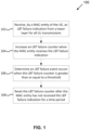
- Fig. 1 is a flowchart of an example method 100 for LBT failure detection performed by a UE, according to an example implementation of the present application.
- a MAC entity of the UE may receive an LBT failure indication from a lower layer (e.g., a PHY layer) for all UL transmissions.
- the LBT failure indication may be regardless of UL transmission types.
- the PHY layer may provide a common LBT failure indication to the MAC entity when LBT fails for different UL transmission operations.
- the PHY layer may send an LBT failure indication to the MAC entity when the PHY layer determines that an LBT procedure of an UL transmission (e.g., regardless of UL transmission types) fails.
- the PHY layer may drop the UL transmission when it determines that the LBT procedure fails.
- the UE may increase an LBT failure counter when the MAC entity receives the LBT failure indication.
- the LBT failure counter is increased by a step value (e.g., 1) whenever the MAC entity receives the LBT failure indication.
- the UE may determine an LBT failure event occurs when the LBT failure counter is greater than or equal to a threshold.
- the threshold may be a parameter (e.g., lbt-FailureInstanceMaxCount ) configured by a configuration (e.g., an RRC configuration).
- the threshold may be broadcast in system information.
- the UE may reset the LBT failure counter after the MAC entity has not received the LBT failure indication for a time period.
- the UE may set the LBT failure counter to an initial value (e.g., 0) when the UE resets the LBT failure counter.
- the time period may be indicated by a configurable timer (e.g., lbt-FailureDetectionTimer ) configured by a configuration (e.g., an RRC configuration).
- the time period may be broadcast in system information.
- An LBT failure may be caused by different operations or different UL transmission types (e.g., transmission of RA preamble, msgA, msg3, SR, or UL data on configured grants).
- there may be one common LBT failure counter for all UL transmission types.
- a MAC entity may determine an LBT failure event occurs.
- k1 may be the maximum number of consecutive LBT failure indications (or consistent LBT failure indications).
- k1 may be a positive integer indicating the threshold in action 106.
- the LBT failure event may also be referred to as a "consistent LBT failure" since the MAC entity consistently receives the LBT failure indication.
- the value of k1 for each operation may be provided in a common signaling (e.g., an LBT configuration that provides LBT related information or parameters).
- the value of k1 for different operations may be provided separately in different signaling.
- the value of k1 for an RA procedure may be provided in a random access related signaling (e.g., dedicated/common RACH configuration)
- the value of k1 for SR may be provided in an SR related signaling
- the value of k1 for configured grants may be provided in a related Configured Grant Configuration.
- the MAC entity may indicate an LBT failure problem to an upper layer (e.g., an RRC layer).
- the MAC entity may indicate the LBT failure problem and the operation that causes the LBT failure problem to the upper layer.
- an LBT failure cause may be used to indicate to the upper layer what kind of failure problem happens to the MAC entity.
- the LBT failure cause may have one or more bits (e.g., 2 bits), where different values may represent the different operations causing the failure. It may depend on UE's implementation whether to indicate different LBT failure causes from the MAC layer to the RRC layer.
- the RRC layer may receive an LBT failure problem related to the SR operation from the MAC layer, and the RRC layer may receive another LBT failure problem related to the RA operation from the MAC layer, and so on.
- the UE may use a UE variable (e.g., the LBT failure counter in action 104), to count the number of consecutive LBT failure indications regardless of the UL transmission types.
- the UE e.g., the MAC entity of the UE
- the UE may set the LBT failure counter to 0 in the initial state.
- the UE e.g., the MAC entity of the UE
- the LBT failure counter may increase the LBT failure counter by 1 when receiving an LBT failure indication for all UL transmissions.
- the UE e.g., the MAC entity of the UE
- the UE e.g., the MAC entity of the UE
- the threshold (e.g., the value of k1 ) may be a fixed value or configured by the network (e.g., via dedicated signaling or via broadcasting in system information). In one implementation, if the threshold is not configured by the network, the UE may apply a default value for the threshold. In one implementation, the UE may first apply the threshold broadcast in system information and then apply a new value of the threshold if configured via dedicated signaling (e.g., RRC signaling).
- dedicated signaling e.g., RRC signaling
- the MAC entity may consider LBT for a UL transmission attempt as successful after the MAC entity has not received an LBT failure indication for a time period.
- the MAC entity may reset the LBT failure counter (e.g., set the LBT failure counter to 0).
- the UE (or the MAC entity of the UE) may reset the LBT failure counter when the MAC entity indicates an LBT failure problem to an upper layer (e.g., an RRC layer).
- the UE may stop the LBT failure counter when the MAC entity indicates the LBT failure problem to the upper layer.
- the UE may reset the LBT failure counter when the UE performs a re-establishment procedure. In one implementation, the UE may reset the LBT failure counter when the UE switches to another carrier, BWP, channel, or LBT unit. In one implementation, the UE may reset the LBT failure counter when a reconfiguration is received related to LBT failure handling (e.g., when at least one of the time period in action 108 and the threshold in action 106 is reconfigured). In one implementation, the UE may reset the LBT failure counter when a reset of the MAC entity is requested (e.g., requested by the upper layers).
- the UE may reset the LBT failure counter when an operating condition changes, such as a change in the operating (or serving) LBT channel, sub-band, BWP, carrier, or cell.
- the UE may reset the LBT failure counter upon RRC state transition (e.g., from the RRC_IDLE state to the RRC_CONNECTED state or from the RRC_INACTIVE state to the RRC_CONNECTED state).
- Fig. 2 is a flowchart of an example method 200 for updating an LBT failure counter performed by a UE, according to an example implementation of the present application.
- the UE may receive a configuration that indicates at least one of the time period (used in action 108 of method 100) and the threshold (used in action 106 of method 100).
- the configuration may be transmitted via dedicated signaling (e.g., RRC signaling) or broadcast in system information.
- the UE may perform a process for LBT failure detection that may be similar to method 100 shown in Fig. 1 .
- Actions 206, 208 and 210 may correspond to three possible conditions to reset the LBT failure counter.
- the UE may reset the LBT failure counter when at least one of the time period and the threshold is reconfigured (e.g., when the UE receives an RRC reconfiguration message that changes at least one of the time period and the threshold).
- the UE may reset the LBT failure counter when the UE switches to another BWP.
- the UE may reset the LBT failure counter when a reset of the MAC entity is requested. It should be noted that although actions 206, 208, and 210 are delineated as separate actions represented as independent blocks in Fig. 2 , these separately delineated actions should not be construed as necessarily order dependent. The order in which the actions are performed in Fig. 2 , is not intended to be construed as a limitation. Moreover, one or more of the actions 206, 208, and 210 may be omitted in some of the present implementations.
- the UE when an upper layer (e.g., the RRC layer) receives an LBT failure problem indication or the LBT failure event occurs because the LBT failure counter is greater than or equal to k1 , the UE (e.g., the RRC layer of the UE) may perform at least one of the following actions based on configurations or pre-defined rules: perform a Radio Link Failure (RLF) recovery procedure, perform a re-establishment procedure, and switch an active BWP of the UE to another BWP or carrier. For example, when the LBT failure event occurs, the UE may switch the active UL BWP to another UL BWP.
- RLF Radio Link Failure
- the UE may switch the active UL BWP to another UL BWP configured with common RACH resources. In some implementations, the UE may transmit an RRC re-establishment request in response to the LBT failure event. In one implementation, if a re-establishment procedure is performed due to an LBT failure problem, the UE may transmit an RRC re-establishment request (e.g., the RRCReestablishmentRequest message) indicating a re-establishment cause as LBT failure. In one implementation, the LBT failure problem indication is common for all operations. In another implementation, there is one specific LBT failure problem indication for each operation.
- the upper layer may perform a specific action (e.g., triggering re-establishment procedure, triggering RLF recovery procedure, and/or switching to another carrier/BWP) based on the specific operation.
- a specific action e.g., triggering re-establishment procedure, triggering RLF recovery procedure, and/or switching to another carrier/BWP
- Fig. 3 is a flowchart of an example method 300 performed by a UE after determining an LBT failure event occurs, according to an example implementation of the present application.
- Action 106 shown in Fig. 3 may be corresponding to action 106 shown in Fig. 1 .
- the UE may perform action 302 to switch an active (UL) BWP of the UE to another (UL) BWP.
- the UE may perform action 304, where the MAC entity of the UE may indicate an LBT failure problem to an upper layer (e.g., the RRC layer).
- an upper layer e.g., the RRC layer
- the UE when an upper layer (e.g., the RRC layer) receives an LBT failure problem indication or the LBT failure event occurs because the LBT failure counter is greater than or equal to the threshold, the UE (e.g., the RRC layer of the UE) may transmit an LBT failure problem report to the network.
- the LBT failure problem report may include information of which LBT channel/carrier/BWP/unit suffers from the LBT failure problem, or which operation suffers from the LBT failure problem.
- a UE determines an LBT failure problem on a Primary Secondary Cell (PSCell) or a Secondary Cell Group (SCG) operating on an unlicensed spectrum, the UE may send an LBT failure problem report or an SCG failure report (including information of the LBT failure problem) to the master node (which may operate on the licensed spectrum or the unlicensed spectrum).
- PSCell Primary Secondary Cell
- SCG Secondary Cell Group
- a UE determines an LBT failure problem on a Primary Cell (PCell) or a Master Cell Group (MCG) operating on the unlicensed spectrum, the UE may send an LBT failure problem report or an MCG failure report (including information of the LBT failure problem) to the secondary node (which may operate on licensed spectrum or unlicensed spectrum).
- PCell Primary Cell
- MCG Master Cell Group
- Fig. 4 is a flowchart of an example method 400 performed by a UE when an LBT failure problem is indicated to an upper layer, according to an example implementation of the present application.
- Action 304 shown in Fig. 4 may be corresponding to action 304 shown in Fig. 3 .
- the UE e.g., the RRC layer of the UE
- the UE may perform an RLF recovery procedure in action 402.
- the MAC entity when the MAC entity instructs a lower layer (e.g., the PHY layer) an attempt to start an UL transmission, the MAC entity may start or restart the LBT success timer for each attempt when the associated resource arrives. In one implementation, when the MAC entity indicates/instructs the lower layer to transmit a random access preamble, the MAC entity may start or restart the LBT success timer in the first symbol of the selected valid PRACH resource. In one implementation, when the MAC entity indicates/instructs the lower layer to signal an SR, the MAC entity may start or restart the LBT success timer in the first symbol of the selected valid PUCCH resource for the SR. In one implementation, when the MAC entity indicates/instructs the lower layer to transmit UL data using configured grants, the MAC entity may start or restart the LBT success timer in the first symbol of the stored uplink configured grants.
- a lower layer e.g., the PHY layer
- the MAC entity may start or restart the LBT success timer for each attempt when the
- the UE may start or restart the LBT success timer when the value(s) of the LBT success timer is reconfigured by the upper layer (e.g., reconfigured by RRC signaling). In one implementation, the UE may start or restart the LBT success timer when an operating condition changes, such as a change in the operating (or serving) LBT channel, sub-band, BWP, carrier, or cell.
- an operating condition changes such as a change in the operating (or serving) LBT channel, sub-band, BWP, carrier, or cell.
- the UE may decide whether LBT is successful or not based on whether a corresponding LBT failure indication is received or not. For example, when the MAC entity indicates/instructs the lower layer to transmit a random access preamble, the MAC entity may consider the LBT for this attempt as successful if the MAC layer does not receive a corresponding LBT failure indication (e.g., at the beginning of the selected valid PRACH resource or at the end of the selected valid PRACH resource).
- a corresponding LBT failure indication e.g., at the beginning of the selected valid PRACH resource or at the end of the selected valid PRACH resource.
- the MAC entity may consider the LBT for the attempt as successful if the MAC entity does not receive a corresponding LBT failure indication (e.g., at the beginning of the selected valid PUCCH resource for the SR or at the end of the selected valid PUCCH resource for the SR).
- the MAC entity may consider the LBT for the attempt as successful if the MAC layer does not receive a corresponding LBT failure indication at the beginning of the stored uplink configured grants or at the end of the stored uplink configured grants.
- the MAC entity may increase the LBT failure counter by 1 when receiving an LBT failure indication.
- the LBT success indication may be regardless of MAC operations (e.g., RACH procedure, SR procedure), and there may be a common LBT failure counter for all MAC operations.
- the MAC entity may decrease the LBT failure counter by 1 for all MAC operations when receiving the LBT success indication.
- the MAC entity may decrease the different LBT failure counters for different MAC operations by 1 when receiving a common LBT success indication.
- the MAC entity may decrease a specific LBT failure counter by 1 when receiving a corresponding LBT success indication for a specific MAC operation.
- the MAC entity may identify which attempt a received common LBT failure indication is associated with. In one implementation, the MAC entity may identify which attempt a received common LBT success indication is associated with. In one implementation, the MAC entity may identify which attempt the received common LBT failure (or success) indication is associated with based on the timing of the resource used/selected by the attempt (e.g., the stored uplink configured grant, the selected PRACH resource, or the valid PUCCH resources for an SR).
- the resource used/selected by the attempt e.g., the stored uplink configured grant, the selected PRACH resource, or the valid PUCCH resources for an SR.
- Fig. 5 is a block diagram illustrating a node for wireless communication, in accordance with various aspects of the present application.
- a node 500 may include a transceiver 520, a processor 528, a memory 534, one or more presentation components 538, and at least one antenna 536.
- the node 500 may also include an RF spectrum band module, a base station (BS) communications module, a network communications module, and a system communications management module, Input/Output (I/O) ports, I/O components, and power supply (not explicitly shown in Fig. 5 ).
- BS base station
- I/O Input/Output
- I/O components I/O components
- power supply not explicitly shown in Fig. 5
- Each of these components may be in communication with each other, directly or indirectly, over one or more buses 540.
- the node 500 may be a UE or a base station that performs various functions described herein, for example, with reference to Figs. 1 through 4 .
- the transceiver 520 having a transmitter 522 (e.g., transmitting/transmission circuitry) and a receiver 524 (e.g., receiving/reception circuitry) may be configured to transmit and/or receive time and/or frequency resource partitioning information.
- the transceiver 520 may be configured to transmit in different types of subframes and slots including, but not limited to, usable, non-usable and flexibly usable subframes and slot formats.
- the transceiver 520 may be configured to receive data and control channels.
- the node 500 may include a variety of computer-readable media.
- Computer-readable media may be any available media that may be accessed by the node 500 and include both volatile and non-volatile media, removable and non-removable media.
- Computer-readable media may comprise computer storage media and communication media.
- Computer storage media include both volatile and non-volatile, removable and non-removable media implemented in any method or technology for storage of information such as computer-readable instructions, data structures, program modules or data.
- Computer storage media includes RAM, ROM, EEPROM, flash memory or other memory technology, CD-ROM, Digital Versatile Disks (DVD) or other optical disk storage, magnetic cassettes, magnetic tape, magnetic disk storage or other magnetic storage devices.
- Computer storage media do not comprise a propagated data signal.
- Communication media typically embody computer-readable instructions, data structures, program modules or other data in a modulated data signal such as a carrier wave or other transport mechanism and includes any information delivery media.
- modulated data signal means a signal that has one or more of its characteristics set or changed in such a manner as to encode information in the signal.
- communication media include wired media such as a wired network or direct-wired connection, and wireless media such as acoustic, RF, infrared and other wireless media. Combinations of any of the above should also be included within the scope of computer-readable media.
- the memory 534 may include computer-storage media in the form of volatile and/or non-volatile memory.
- the memory 534 may be removable, non-removable, or a combination thereof.
- Example memory includes solid-state memory, hard drives, optical-disc drives, and etc.
- the memory 534 may store computer-readable, computer-executable instructions 532 (e.g., software codes) that are configured to, when executed, cause the processor 528 to perform various functions described herein, for example, with reference to Figs. 1 through 4 .
- the instructions 532 may not be directly executable by the processor 528 but be configured to cause the node 500 (e.g., when compiled and executed) to perform various functions described herein.
- the processor 528 may include an intelligent hardware device, e.g., a Central Processing Unit (CPU), a microcontroller, an ASIC, and etc.
- the processor 528 may include memory.
- the processor 528 may process the data 530 and the instructions 532 received from the memory 534, and information through the transceiver 520, the base band communications module, and/or the network communications module.
- the processor 528 may also process information to be sent to the transceiver 520 for transmission through the antenna 536, to the network communications module for transmission to a core network.
- presentation components 538 presents data indications to a person or other device.
- presentation components 538 may include a display device, speaker, printing component, vibrating component, etc.
Landscapes
- Engineering & Computer Science (AREA)
- Computer Networks & Wireless Communication (AREA)
- Signal Processing (AREA)
- Mobile Radio Communication Systems (AREA)
Applications Claiming Priority (4)
| Application Number | Priority Date | Filing Date | Title |
|---|---|---|---|
| US201962790099P | 2019-01-09 | 2019-01-09 | |
| EP20739185.5A EP3909331B1 (fr) | 2019-01-09 | 2020-01-08 | Procédé et appareil pour détection de défaillance lbt |
| EP23215599.4A EP4311327B1 (fr) | 2019-01-09 | 2020-01-08 | Procédé et appareil pour détection de défaillance lbt |
| PCT/CN2020/070940 WO2020143672A1 (fr) | 2019-01-09 | 2020-01-08 | Procédé et appareil pour détection de défaillance lbt |
Related Parent Applications (2)
| Application Number | Title | Priority Date | Filing Date |
|---|---|---|---|
| EP20739185.5A Division EP3909331B1 (fr) | 2019-01-09 | 2020-01-08 | Procédé et appareil pour détection de défaillance lbt |
| EP23215599.4A Division EP4311327B1 (fr) | 2019-01-09 | 2020-01-08 | Procédé et appareil pour détection de défaillance lbt |
Publications (2)
| Publication Number | Publication Date |
|---|---|
| EP4580274A2 true EP4580274A2 (fr) | 2025-07-02 |
| EP4580274A3 EP4580274A3 (fr) | 2025-08-06 |
Family
ID=71404694
Family Applications (3)
| Application Number | Title | Priority Date | Filing Date |
|---|---|---|---|
| EP25171709.6A Pending EP4580274A3 (fr) | 2019-01-09 | 2020-01-08 | Procédé et appareil de détection de défaillance lbt |
| EP23215599.4A Active EP4311327B1 (fr) | 2019-01-09 | 2020-01-08 | Procédé et appareil pour détection de défaillance lbt |
| EP20739185.5A Active EP3909331B1 (fr) | 2019-01-09 | 2020-01-08 | Procédé et appareil pour détection de défaillance lbt |
Family Applications After (2)
| Application Number | Title | Priority Date | Filing Date |
|---|---|---|---|
| EP23215599.4A Active EP4311327B1 (fr) | 2019-01-09 | 2020-01-08 | Procédé et appareil pour détection de défaillance lbt |
| EP20739185.5A Active EP3909331B1 (fr) | 2019-01-09 | 2020-01-08 | Procédé et appareil pour détection de défaillance lbt |
Country Status (6)
| Country | Link |
|---|---|
| US (4) | US11272535B2 (fr) |
| EP (3) | EP4580274A3 (fr) |
| CN (2) | CN113273269B (fr) |
| ES (1) | ES3036764T3 (fr) |
| MX (1) | MX2021008190A (fr) |
| WO (1) | WO2020143672A1 (fr) |
Families Citing this family (49)
| Publication number | Priority date | Publication date | Assignee | Title |
|---|---|---|---|---|
| US11388636B2 (en) * | 2019-12-06 | 2022-07-12 | Qualcomm Incorporated | Mobility enhancements for unlicensed operation |
| US11032866B2 (en) * | 2017-11-27 | 2021-06-08 | FG Innovation Company Limited | Methods and related devices for multi-connectivity |
| EP4580274A3 (fr) | 2019-01-09 | 2025-08-06 | Hannibal IP LLC | Procédé et appareil de détection de défaillance lbt |
| US11838773B2 (en) * | 2019-01-16 | 2023-12-05 | Beijing Xiaomi Mobile Software Co., Ltd. | LBT failure processing method and LBT failure processing apparatus |
| DK3915301T3 (da) * | 2019-01-25 | 2024-07-08 | Zte Corp | Fremgangsmåde og indretning til rapportering af en fejl af en hovedcellegruppe |
| US10869336B2 (en) * | 2019-02-15 | 2020-12-15 | Qualcomm Incorporated | Random access channel access and validity procedures |
| US12095498B2 (en) * | 2019-03-22 | 2024-09-17 | Lg Electronics Inc. | Method and apparatus for handling radio link failure on unlicensed frequency in a wireless communication system |
| ES3030714T3 (en) * | 2019-03-27 | 2025-07-01 | Beijing Xiaomi Mobile Software Co Ltd | Channel indication method and apparatus |
| KR102880148B1 (ko) | 2019-03-28 | 2025-11-04 | 삼성전자주식회사 | 비면허 대역을 활용하는 무선통신시스템에서 상향링크 LBT (Listen-Before-Talk) 실패를 감지하는 방법 및 장치 |
| EP3949655A1 (fr) * | 2019-03-28 | 2022-02-09 | Telefonaktiebolaget LM Ericsson (publ) | Adaptation de procédures de cellule de desserte d'ue sur la base d'informations opérationnelles cca dl |
| CN111614447B (zh) * | 2019-04-01 | 2021-11-02 | 维沃移动通信有限公司 | 无线链路状态指示上报方法和终端设备 |
| US11497054B2 (en) * | 2019-05-02 | 2022-11-08 | Qualcomm Incorporated | Channel congestion measurement |
| CN111615146B (zh) * | 2019-06-28 | 2023-01-10 | 维沃移动通信有限公司 | 处理方法及设备 |
| WO2021008174A1 (fr) * | 2019-07-12 | 2021-01-21 | Telefonaktiebolaget Lm Ericsson (Publ) | Procédés, dispositif terminal et nœud de réseau destinés à une transmission sens montant |
| CN113196851B (zh) * | 2019-07-18 | 2023-06-13 | Oppo广东移动通信有限公司 | 信息上报方法及相关设备 |
| US11558899B2 (en) * | 2019-08-15 | 2023-01-17 | Industrial Technology Research Institute | Method and user equipment of performing resource switching in unlicensed spectrum |
| US10980059B1 (en) * | 2019-12-01 | 2021-04-13 | PanPsy Technologies, LLC | Recovery from consistent uplink listen before talk failure |
| US10979128B1 (en) | 2019-12-07 | 2021-04-13 | PanPsy Technologies, LLC | Beam failure and consistent listen before talk failure recovery |
| US10980062B1 (en) * | 2019-12-16 | 2021-04-13 | PanPsy Technologies, LLC | Wireless device and wireless network processes and consistent LBT failures |
| US12356449B2 (en) * | 2020-02-05 | 2025-07-08 | Lenovo (Singapore) Pte. Ltd. | LBT procedure for a set of panels and/or beams |
| CN113497688A (zh) * | 2020-04-02 | 2021-10-12 | 维沃移动通信有限公司 | 调度请求的配置方法、终端及网络设备 |
| US11570812B2 (en) * | 2020-04-23 | 2023-01-31 | Mediatek Singapore Pte. Ltd. | Conditions on listen-before-talk impact on mac counters in mobile communications |
| US11582796B2 (en) * | 2020-05-15 | 2023-02-14 | Qualcomm Incorporated | Listen-before-talk (LBT) failure detection in dormant cell and outside discontinuous reception (DRX) active time |
| EP4066555B1 (fr) * | 2020-05-21 | 2025-07-16 | ZTE Corporation | Configurations pour des transmissions de données économisant les ressources dans un accès à un canal à spectre partagé |
| US20220014991A1 (en) * | 2020-07-13 | 2022-01-13 | Qualcomm Incorporated | Success response for l1/l2 based inter-cell mobility |
| GB2597793A (en) * | 2020-08-06 | 2022-02-09 | Nec Corp | Communication system |
| WO2022027552A1 (fr) * | 2020-08-07 | 2022-02-10 | Lenovo (Beijing) Limited | Procédés et appareil de fourniture d'informations d'assistant pour une planification de liaison montante |
| KR20230048315A (ko) * | 2020-08-07 | 2023-04-11 | 퀄컴 인코포레이티드 | 공유 스펙트럼 상에서의 채널 액세스 실패 정보 |
| WO2022047629A1 (fr) * | 2020-09-01 | 2022-03-10 | Oppo广东移动通信有限公司 | Procédé de signalement de situation d'accès aléatoire, dispositif terminal et dispositif de réseau |
| WO2022073206A1 (fr) * | 2020-10-09 | 2022-04-14 | Oppo广东移动通信有限公司 | Procédé et dispositif de communication sans fil |
| WO2022082640A1 (fr) * | 2020-10-22 | 2022-04-28 | Nokia Shanghai Bell Co., Ltd. | Enregistrement d'annulation de défaillance |
| CN115396926A (zh) * | 2020-10-22 | 2022-11-25 | 荣耀终端有限公司 | 处理网络注册异常的方法、装置、存储介质和芯片 |
| WO2022104542A1 (fr) * | 2020-11-17 | 2022-05-27 | Oppo广东移动通信有限公司 | Procédé de communication sans fil et appareil de communication |
| WO2022104589A1 (fr) * | 2020-11-18 | 2022-05-27 | Lenovo (Beijing) Limited | Procédé et appareil pour la transmission de petites données |
| US11570820B2 (en) * | 2020-12-18 | 2023-01-31 | Qualcomm Incorporated | Listen-before-talk failure reporting for sidelink channels |
| CN115315017A (zh) * | 2021-05-06 | 2022-11-08 | 展讯通信(上海)有限公司 | 一种资源处理方法、设备、介质、芯片及芯片模组 |
| US12167453B2 (en) * | 2021-07-19 | 2024-12-10 | Qualcomm Incorporated | Techniques for listen-before-talk failure reporting for multiple transmission time intervals |
| CN115734202A (zh) * | 2021-08-31 | 2023-03-03 | 华为技术有限公司 | 旁链路通信方法及设备 |
| CN115835418B (zh) * | 2021-09-16 | 2026-01-27 | 维沃软件技术有限公司 | 连续lbt失败处理方法及装置、终端及网络侧设备 |
| CN117643101A (zh) * | 2021-10-29 | 2024-03-01 | Oppo广东移动通信有限公司 | 无线通信的方法及终端设备 |
| KR20250003824A (ko) * | 2022-04-26 | 2025-01-07 | 엘지전자 주식회사 | 무선 통신 시스템에서 사이드링크 통신을 수행하는 방법 및 장치 |
| WO2023211206A1 (fr) * | 2022-04-28 | 2023-11-02 | 엘지전자 주식회사 | Procédé et appareil pour effectuer une communication sans fil associée à une lbt |
| US20240023109A1 (en) * | 2022-07-13 | 2024-01-18 | Qualcomm Incorporated | Configured grant sidelink communications in a shared or unlicensed frequency band |
| CN119678638A (zh) * | 2022-08-01 | 2025-03-21 | 株式会社Kt | 一种侧行链路通信失败处理方法及其装置 |
| WO2024031373A1 (fr) * | 2022-08-09 | 2024-02-15 | 北京小米移动软件有限公司 | Procédé et appareil de détermination selon laquelle des défaillances de procédure lbt continues sont déclenchées |
| WO2024035220A1 (fr) * | 2022-08-11 | 2024-02-15 | 엘지전자 주식회사 | Procédé et dispositif de reprise après défaillance lbt de sl dans des bandes sans licence |
| KR20240063618A (ko) | 2022-11-03 | 2024-05-10 | 삼성전자주식회사 | 이동 통신 시스템에서 LBT (listen-before-talk) 실패 정보를 기록하는 방법 및 장치 |
| WO2024093052A1 (fr) * | 2023-02-17 | 2024-05-10 | Lenovo (Beijing) Limited | Dispositif terminal et procédé de communication sur liaison latérale |
| EP4694558A1 (fr) * | 2023-04-07 | 2026-02-11 | Datang Mobile Communications Equipment Co., Ltd. | Procédé et appareil de traitement de défaillance de procédure « écouter avant de parler » cohérente, et terminal |
Family Cites Families (26)
| Publication number | Priority date | Publication date | Assignee | Title |
|---|---|---|---|---|
| WO2010017376A1 (fr) | 2008-08-08 | 2010-02-11 | Interdigital Patent Holdings, Inc. | Réinitialisation et reconfiguration d’une entité mac |
| US10477574B2 (en) * | 2015-04-10 | 2019-11-12 | Lg Electronics Inc. | Method and apparatus for performing contention based random access procedure over contention free random access procedure in wireless communication system |
| US10187907B2 (en) * | 2015-07-05 | 2019-01-22 | Ofinno Technologies, Llc | Preamble transmission in a wireless device |
| US20170231005A1 (en) * | 2016-02-04 | 2017-08-10 | Ofinno Technologies, Llc | Channel access counter in a wireless network |
| US10893548B2 (en) * | 2016-03-31 | 2021-01-12 | Intel IP Corporation | Physical random access channel design for licensed assisted access |
| CN107371168A (zh) * | 2016-05-12 | 2017-11-21 | 电信科学技术研究院 | 一种非授权频谱中的测量方法和设备 |
| GB2550200B (en) | 2016-05-13 | 2021-08-04 | Tcl Communication Ltd | Methods and devices for supporting access to unlicensed radio resources in wireless communication systems |
| CN107770868A (zh) | 2016-08-19 | 2018-03-06 | 中兴通讯股份有限公司 | 一种控制信元取消方法、装置及终端 |
| US20180124831A1 (en) * | 2016-10-29 | 2018-05-03 | Ofinno Technologies, Llc | Dual connectivity scheduling request for wireless network and wireless device |
| US10681738B2 (en) * | 2016-12-16 | 2020-06-09 | Ofinno, Llc | Random access in a wireless device and wireless network |
| US10484931B2 (en) * | 2016-12-23 | 2019-11-19 | Ofinno, Llc | Licensed assisted access radio link failure |
| CN108633097B (zh) * | 2017-03-24 | 2023-05-09 | 北京三星通信技术研究有限公司 | 无线通信方法和用户设备 |
| CN111869307B (zh) * | 2018-02-13 | 2024-04-09 | 交互数字专利控股公司 | 用于非授权资源选择的方法 |
| US10880895B2 (en) * | 2018-05-27 | 2020-12-29 | Brian Gordaychik | Variable length downlink control information formats for next generation radio technologies |
| US11956822B2 (en) * | 2018-06-19 | 2024-04-09 | Interdigital Patent Holdings, Inc. | Radio link monitoring in shared spectrum |
| KR102265329B1 (ko) * | 2018-08-30 | 2021-06-16 | 주식회사 케이티 | 비면허 대역에서의 채널 접속 실패를 처리하는 방법 및 장치 |
| US11202320B2 (en) * | 2018-09-05 | 2021-12-14 | Samsung Electronics Co., Ltd. | Method and apparatus of performing random access on unlicensed carrier |
| EP3841823A1 (fr) | 2018-09-26 | 2021-06-30 | Convida Wireless, Llc | Procédures de contrôle d'accès au support de répéteur au sol de technologie nr-u |
| WO2020092359A1 (fr) | 2018-10-31 | 2020-05-07 | Intel Corporation | Améliorations de demandes d'ordonnancement pour des réseaux 5g |
| JP7353365B2 (ja) | 2018-10-31 | 2023-09-29 | オッポ広東移動通信有限公司 | カウント方法、端末デバイス及び装置 |
| US10925093B2 (en) * | 2018-11-13 | 2021-02-16 | Mediatek Singapore Pte. Ltd. | Method and apparatus for detecting consistent listen before talk failure in mobile communications |
| US20200221309A1 (en) * | 2019-01-07 | 2020-07-09 | Qualcomm Incorporated | Handling of channel access problems |
| EP4580274A3 (fr) | 2019-01-09 | 2025-08-06 | Hannibal IP LLC | Procédé et appareil de détection de défaillance lbt |
| US10869336B2 (en) * | 2019-02-15 | 2020-12-15 | Qualcomm Incorporated | Random access channel access and validity procedures |
| GB2583739B (en) | 2019-05-07 | 2022-05-18 | Sensorhut Ltd | Detection of analytes in gases using porous sorbents |
| US11950279B2 (en) * | 2019-09-30 | 2024-04-02 | Comcast Cable Communications, Llc | Communication channel failure detection and recovery |
-
2020
- 2020-01-08 EP EP25171709.6A patent/EP4580274A3/fr active Pending
- 2020-01-08 CN CN202080008293.1A patent/CN113273269B/zh active Active
- 2020-01-08 WO PCT/CN2020/070940 patent/WO2020143672A1/fr not_active Ceased
- 2020-01-08 ES ES23215599T patent/ES3036764T3/es active Active
- 2020-01-08 US US16/737,787 patent/US11272535B2/en active Active
- 2020-01-08 MX MX2021008190A patent/MX2021008190A/es unknown
- 2020-01-08 CN CN202410284231.3A patent/CN118055466A/zh active Pending
- 2020-01-08 EP EP23215599.4A patent/EP4311327B1/fr active Active
- 2020-01-08 EP EP20739185.5A patent/EP3909331B1/fr active Active
-
2022
- 2022-02-04 US US17/592,664 patent/US11805544B2/en active Active
-
2023
- 2023-09-21 US US18/370,986 patent/US12408193B2/en active Active
-
2025
- 2025-07-16 US US19/271,288 patent/US20260046921A1/en active Pending
Also Published As
| Publication number | Publication date |
|---|---|
| MX2021008190A (es) | 2021-08-11 |
| US20260046921A1 (en) | 2026-02-12 |
| EP4311327A3 (fr) | 2024-02-21 |
| US12408193B2 (en) | 2025-09-02 |
| US11272535B2 (en) | 2022-03-08 |
| ES3036764T3 (en) | 2025-09-24 |
| WO2020143672A1 (fr) | 2020-07-16 |
| EP3909331B1 (fr) | 2023-12-13 |
| US20220232622A1 (en) | 2022-07-21 |
| US20200221495A1 (en) | 2020-07-09 |
| EP4580274A3 (fr) | 2025-08-06 |
| EP4311327B1 (fr) | 2025-04-23 |
| EP3909331A1 (fr) | 2021-11-17 |
| EP4311327A2 (fr) | 2024-01-24 |
| CN113273269A (zh) | 2021-08-17 |
| US20240090019A1 (en) | 2024-03-14 |
| EP3909331A4 (fr) | 2022-08-24 |
| CN118055466A (zh) | 2024-05-17 |
| CN113273269B (zh) | 2024-04-02 |
| US11805544B2 (en) | 2023-10-31 |
Similar Documents
| Publication | Publication Date | Title |
|---|---|---|
| US12408193B2 (en) | Method and apparatus for LBT failure detection | |
| US12096266B2 (en) | Method and apparatus for handling measurement in wireless communication system | |
| US20230209610A1 (en) | Two-step random access procedure in next generation wireless networks | |
| US12349082B2 (en) | Method of small data transmission and related device | |
| US11064538B2 (en) | Methods and apparatuses for performing random access procedures | |
| CN114651520B (zh) | 先听后说恢复过程的方法及相关设备 | |
| US11153913B2 (en) | Random access procedure in next generation wireless networks | |
| US11664879B2 (en) | Method and apparatus for handling BWP switching in random access procedure | |
| WO2021135941A1 (fr) | Procédé et équipement d'utilisateur pour une petite transmission de données | |
| EP4070616B1 (fr) | Procédé de procédure d'accès aléatoire et dispositif associé | |
| US20210051499A1 (en) | Method and apparatus for radio link monitoring | |
| US12363758B2 (en) | Method related to random access and user equipment |
Legal Events
| Date | Code | Title | Description |
|---|---|---|---|
| PUAI | Public reference made under article 153(3) epc to a published international application that has entered the european phase |
Free format text: ORIGINAL CODE: 0009012 |
|
| STAA | Information on the status of an ep patent application or granted ep patent |
Free format text: STATUS: THE APPLICATION HAS BEEN PUBLISHED |
|
| AC | Divisional application: reference to earlier application |
Ref document number: 3909331 Country of ref document: EP Kind code of ref document: P Ref document number: 4311327 Country of ref document: EP Kind code of ref document: P |
|
| AK | Designated contracting states |
Kind code of ref document: A2 Designated state(s): AL AT BE BG CH CY CZ DE DK EE ES FI FR GB GR HR HU IE IS IT LI LT LU LV MC MK MT NL NO PL PT RO RS SE SI SK SM TR |
|
| REG | Reference to a national code |
Ref country code: DE Ref legal event code: R079 Free format text: PREVIOUS MAIN CLASS: H04W0072000000 Ipc: H04W0074080000 |
|
| PUAL | Search report despatched |
Free format text: ORIGINAL CODE: 0009013 |
|
| STAA | Information on the status of an ep patent application or granted ep patent |
Free format text: STATUS: REQUEST FOR EXAMINATION WAS MADE |
|
| AK | Designated contracting states |
Kind code of ref document: A3 Designated state(s): AL AT BE BG CH CY CZ DE DK EE ES FI FR GB GR HR HU IE IS IT LI LT LU LV MC MK MT NL NO PL PT RO RS SE SI SK SM TR |
|
| RIC1 | Information provided on ipc code assigned before grant |
Ipc: H04W 74/08 20240101AFI20250702BHEP Ipc: H04W 72/00 20230101ALI20250702BHEP |
|
| 17P | Request for examination filed |
Effective date: 20250724 |
|
| REG | Reference to a national code |
Ref country code: DE Ref legal event code: R079 Free format text: PREVIOUS MAIN CLASS: H04W0074080000 Ipc: H04W0036300000 |
|
| GRAP | Despatch of communication of intention to grant a patent |
Free format text: ORIGINAL CODE: EPIDOSNIGR1 |
|
| STAA | Information on the status of an ep patent application or granted ep patent |
Free format text: STATUS: GRANT OF PATENT IS INTENDED |
|
| RIC1 | Information provided on ipc code assigned before grant |
Ipc: H04W 36/30 20090101AFI20251112BHEP Ipc: H04W 74/08 20240101ALI20251112BHEP Ipc: H04W 72/00 20230101ALI20251112BHEP |
|
| INTG | Intention to grant announced |
Effective date: 20251124 |