EP4580268A1 - Verfahren und vorrichtung zur uplink-leistungssteuerung in einem kommunikationssystem mit mprp-unterstützung - Google Patents
Verfahren und vorrichtung zur uplink-leistungssteuerung in einem kommunikationssystem mit mprp-unterstützung Download PDFInfo
- Publication number
- EP4580268A1 EP4580268A1 EP23886133.0A EP23886133A EP4580268A1 EP 4580268 A1 EP4580268 A1 EP 4580268A1 EP 23886133 A EP23886133 A EP 23886133A EP 4580268 A1 EP4580268 A1 EP 4580268A1
- Authority
- EP
- European Patent Office
- Prior art keywords
- transmission power
- panel
- transmission
- terminal
- base station
- Prior art date
- Legal status (The legal status is an assumption and is not a legal conclusion. Google has not performed a legal analysis and makes no representation as to the accuracy of the status listed.)
- Pending
Links
Images


Classifications
-
- H—ELECTRICITY
- H04—ELECTRIC COMMUNICATION TECHNIQUE
- H04B—TRANSMISSION
- H04B7/00—Radio transmission systems, i.e. using radiation field
- H04B7/02—Diversity systems; Multi-antenna system, i.e. transmission or reception using multiple antennas
- H04B7/04—Diversity systems; Multi-antenna system, i.e. transmission or reception using multiple antennas using two or more spaced independent antennas
- H04B7/06—Diversity systems; Multi-antenna system, i.e. transmission or reception using multiple antennas using two or more spaced independent antennas at the transmitting station
- H04B7/0686—Hybrid systems, i.e. switching and simultaneous transmission
- H04B7/0691—Hybrid systems, i.e. switching and simultaneous transmission using subgroups of transmit antennas
-
- H—ELECTRICITY
- H04—ELECTRIC COMMUNICATION TECHNIQUE
- H04B—TRANSMISSION
- H04B7/00—Radio transmission systems, i.e. using radiation field
- H04B7/02—Diversity systems; Multi-antenna system, i.e. transmission or reception using multiple antennas
- H04B7/04—Diversity systems; Multi-antenna system, i.e. transmission or reception using multiple antennas using two or more spaced independent antennas
- H04B7/0413—MIMO systems
- H04B7/0426—Power distribution
-
- H—ELECTRICITY
- H04—ELECTRIC COMMUNICATION TECHNIQUE
- H04B—TRANSMISSION
- H04B7/00—Radio transmission systems, i.e. using radiation field
- H04B7/02—Diversity systems; Multi-antenna system, i.e. transmission or reception using multiple antennas
- H04B7/04—Diversity systems; Multi-antenna system, i.e. transmission or reception using multiple antennas using two or more spaced independent antennas
- H04B7/06—Diversity systems; Multi-antenna system, i.e. transmission or reception using multiple antennas using two or more spaced independent antennas at the transmitting station
-
- H—ELECTRICITY
- H04—ELECTRIC COMMUNICATION TECHNIQUE
- H04W—WIRELESS COMMUNICATION NETWORKS
- H04W52/00—Power management, e.g. Transmission Power Control [TPC] or power classes
- H04W52/04—Transmission power control [TPC]
- H04W52/06—TPC algorithms
- H04W52/14—Separate analysis of uplink or downlink
- H04W52/146—Uplink power control
-
- H—ELECTRICITY
- H04—ELECTRIC COMMUNICATION TECHNIQUE
- H04W—WIRELESS COMMUNICATION NETWORKS
- H04W52/00—Power management, e.g. Transmission Power Control [TPC] or power classes
- H04W52/04—Transmission power control [TPC]
- H04W52/18—TPC being performed according to specific parameters
- H04W52/24—TPC being performed according to specific parameters using SIR [Signal to Interference Ratio] or other wireless path parameters
- H04W52/241—TPC being performed according to specific parameters using SIR [Signal to Interference Ratio] or other wireless path parameters taking into account channel quality metrics, e.g. SIR, SNR, CIR or Eb/lo
-
- H—ELECTRICITY
- H04—ELECTRIC COMMUNICATION TECHNIQUE
- H04W—WIRELESS COMMUNICATION NETWORKS
- H04W52/00—Power management, e.g. Transmission Power Control [TPC] or power classes
- H04W52/04—Transmission power control [TPC]
- H04W52/18—TPC being performed according to specific parameters
- H04W52/28—TPC being performed according to specific parameters using user profile, e.g. mobile speed, priority or network state, e.g. standby, idle or non-transmission
- H04W52/281—TPC being performed according to specific parameters using user profile, e.g. mobile speed, priority or network state, e.g. standby, idle or non-transmission taking into account user or data type priority
-
- H—ELECTRICITY
- H04—ELECTRIC COMMUNICATION TECHNIQUE
- H04W—WIRELESS COMMUNICATION NETWORKS
- H04W52/00—Power management, e.g. Transmission Power Control [TPC] or power classes
- H04W52/04—Transmission power control [TPC]
- H04W52/30—Transmission power control [TPC] using constraints in the total amount of available transmission power
- H04W52/32—TPC of broadcast or control channels
- H04W52/325—Power control of control or pilot channels
-
- H—ELECTRICITY
- H04—ELECTRIC COMMUNICATION TECHNIQUE
- H04W—WIRELESS COMMUNICATION NETWORKS
- H04W52/00—Power management, e.g. Transmission Power Control [TPC] or power classes
- H04W52/04—Transmission power control [TPC]
- H04W52/30—Transmission power control [TPC] using constraints in the total amount of available transmission power
- H04W52/34—TPC management, i.e. sharing limited amount of power among users or channels or data types, e.g. cell loading
- H04W52/346—TPC management, i.e. sharing limited amount of power among users or channels or data types, e.g. cell loading distributing total power among users or channels
-
- H—ELECTRICITY
- H04—ELECTRIC COMMUNICATION TECHNIQUE
- H04W—WIRELESS COMMUNICATION NETWORKS
- H04W52/00—Power management, e.g. Transmission Power Control [TPC] or power classes
- H04W52/04—Transmission power control [TPC]
- H04W52/30—Transmission power control [TPC] using constraints in the total amount of available transmission power
- H04W52/36—Transmission power control [TPC] using constraints in the total amount of available transmission power with a discrete range or set of values, e.g. step size, ramping or offsets
- H04W52/367—Power values between minimum and maximum limits, e.g. dynamic range
-
- H—ELECTRICITY
- H04—ELECTRIC COMMUNICATION TECHNIQUE
- H04W—WIRELESS COMMUNICATION NETWORKS
- H04W52/00—Power management, e.g. Transmission Power Control [TPC] or power classes
- H04W52/04—Transmission power control [TPC]
- H04W52/38—TPC being performed in particular situations
- H04W52/42—TPC being performed in particular situations in systems with time, space, frequency or polarisation diversity
-
- H—ELECTRICITY
- H04—ELECTRIC COMMUNICATION TECHNIQUE
- H04W—WIRELESS COMMUNICATION NETWORKS
- H04W8/00—Network data management
- H04W8/22—Processing or transfer of terminal data, e.g. status or physical capabilities
- H04W8/24—Transfer of terminal data
Definitions
- a communication network (e.g., 5G communication network or 6G communication network) is being developed to provide enhanced communication services compared to the existing communication networks (e.g., long term evolution (LTE), LTE-Advanced (LTE-A), etc.).
- the 5G communication network e.g., New Radio (NR) communication network
- NR New Radio
- NR New Radio
- FR1 frequency region 1
- the 5G communication network can support various communication services and scenarios.
- usage scenarios of the 5G communication network may include enhanced Mobile BroadBand (eMBB), Ultra Reliable Low Latency Communication (URLLC), massive Machine Type Communication (mMTC), and the like.
- eMBB enhanced Mobile BroadBand
- URLLC Ultra Reliable Low Latency Communication
- mMTC massive Machine Type Communication
- At least one of A and B may refer to “at least one of A or B” or “at least one of combinations of one or more of A and B".
- one or more of A and B may refer to "one or more of A or B" or "one or more of combinations of one or more of A and B”.
- the MAC signaling may refer to an operation of transmitting and receiving a MAC control element (CE).
- CE MAC control element
- the PHY signaling may refer to an operation of transmitting and receiving control information (e.g., downlink control information (DCI), uplink control information (UCI), or sidelink control information (SCI)).
- DCI downlink control information
- UCI uplink control information
- SCI sidelink control information
- the signaling may refer to signaling between a base station and a terminal and/or signaling between terminals.
- 'configuration of an operation may refer to signaling of configuration information (e.g., information elements, parameters) required for the operation and/or information indicating to perform the operation.
- 'configuration of information elements (e.g., parameters)' may refer to signaling of the information elements.
- 'signal and/or channel' may refer to signal, channel, or both signal and channel, and 'signal' may be used to mean 'signal and/or channel'.
- information may be used to refer to an information element, a field, a field value, field information, and/or a parameter.
- a communication network to which exemplary embodiments are applied is not limited to that described below, and the exemplary embodiments may be applied to various communication networks (e.g., 4G communication networks, 5G communication networks, and/or 6G communication networks).
- 'communication network' may be used interchangeably with a term 'communication system'.
- FIG. 1 is a conceptual diagram illustrating a first exemplary embodiment of a communication system.
- a communication system 100 may comprise a plurality of communication nodes 110-1, 110-2, 110-3, 120-1, 120-2, 130-1, 130-2, 130-3, 130-4, 130-5, and 130-6.
- the communication system 100 may further include a core network (e.g., a serving gateway (S-GW), a packet data network (PDN) gateway (P-GW), a mobility management entity (MME).
- a core network e.g., a serving gateway (S-GW), a packet data network (PDN) gateway (P-GW), a mobility management entity (MME).
- S-GW serving gateway
- PDN packet data network gateway
- MME mobility management entity
- the core network may include an access and mobility management function (AMF), a user plane function (UPF), a session management function (SMF), and the like.
- AMF access and mobility management function
- UPF user plane function
- SMF session management function
- the plurality of communication nodes 110 to 130 may support communication protocols (e.g., LTE communication protocol, LTE-A communication protocol, NR communication protocol, etc.) specified in 3rd generation partnership project (3GPP) standards.
- the plurality of communication nodes 110 to 130 may support a code division multiple access (CDMA) technique, a wideband CDMA (WCDMA) technique, a time division multiple access (TDMA) technique, a frequency division multiple access (FDMA) technique, an orthogonal frequency division multiplexing (OFDM) technique, a filtered OFDM technique, a cyclic prefix OFDM (CP-OFDM) technique, a discrete Fourier transform spread OFDM (DFT-s-OFDM) technique, an orthogonal frequency division multiple access (OFDMA) technique, a single carrier FDMA (SC-FDMA) technique, a non-orthogonal multiple access (NOMA) technique, a generalized frequency division multiplexing (GFDM) technique, a filter bank multi-carrier (FBMC)
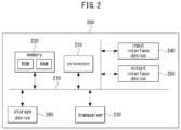
- FIG. 2 is a block diagram illustrating a first exemplary embodiment of a communication node constituting a communication system.
- each of the plurality of base stations 110-1, 110-2, 110-3, 120-1, and 120-2 may refer to a Node-B, evolved Node-B (eNB), gNB, advanced base station (ABS), high reliability-base station (HR-BS), base transceiver station (BTS), radio base station, radio transceiver, access point, access node, radio access station (RAS), mobile multihop relay-base station (MMR-BS), relay station (RS), advanced relay station (ARS), high reliability-relay station (HR-RS), home NodeB (HNB), home eNodeB (HeNB), road side unit (RSU), radio remote head (RRH), transmission point (TP), transmission and reception point (TRP), or the like.
- eNB evolved Node-B
- gNB advanced base station
- ABS high reliability-base station
- BTS base transceiver station
- RAS mobile multihop relay-base station
- RS relay station
- ARS advanced relay station
- HR-RS home NodeB
- Each of the plurality of terminals 130-1, 130-2, 130-3, 130-4, 130-5, and 130-6 may refer to a user equipment (UE), terminal equipment (TE), advanced mobile station (AMS), high reliability-mobile station (HR-MS), terminal, access terminal, mobile terminal, station, subscriber station, mobile station, portable subscriber station, node, device, on-board unit (OBU), or the like.
- UE user equipment
- TE terminal equipment
- AMS advanced mobile station
- HR-MS high reliability-mobile station
- OBU on-board unit
- each of the plurality of base stations 110-1, 110-2, 110-3, 120-1, and 120-2 may operate in the same frequency band or in different frequency bands.
- the plurality of base stations 110-1, 110-2, 110-3, 120-1, and 120-2 may be connected to each other via an ideal backhaul or a non-ideal backhaul, and exchange information with each other via the ideal or non-ideal backhaul.
- each of the plurality of base stations 110-1, 110-2, 110-3, 120-1, and 120-2 may be connected to the core network through the ideal or non-ideal backhaul.
- Each of the plurality of base stations 110-1, 110-2, 110-3, 120-1, and 120-2 may transmit a signal received from the core network to the corresponding terminal 130-1, 130-2, 130-3, 130-4, 130-5, or 130-6, and transmit a signal received from the corresponding terminal 130-1, 130-2, 130-3, 130-4, 130-5, or 130-6 to the core network.
- each of the plurality of base stations 110-1, 110-2, 110-3, 120-1, and 120-2 may support multi-input multi-output (MIMO) transmission (e.g., a single-user MIMO (SU-MIMO), multi-user MIMO (MU-MIMO), massive MIMO, or the like), coordinated multipoint (CoMP) transmission, carrier aggregation (CA) transmission, transmission in an unlicensed band, sidelink communication (e.g., device-to-device (D2D) communication, proximity services (ProSe)), Internet of Things (IoT) communication, dual connectivity (DC), and/or the like.
- MIMO multi-input multi-output
- SU-MIMO single-user MIMO
- MU-MIMO multi-user MIMO
- massive MIMO massive MIMO
- CoMP coordinated multipoint
- CA carrier aggregation
- sidelink communication e.g., device-to-device (D2D) communication, proximity services (ProSe)
- IoT Internet of Things
- each of the plurality of terminals 130-1, 130-2, 130-3, 130-4, 130-5, and 130-6 may perform operations corresponding to the operations of the plurality of base stations 110-1, 110-2, 110-3, 120-1, and 120-2, and operations supported by the plurality of base stations 110-1, 110-2, 110-3, 120-1, and 120-2.
- the second base station 110-2 may transmit a signal to the fourth terminal 130-4 in the SU-MIMO manner, and the fourth terminal 130-4 may receive the signal from the second base station 110-2 in the SU-MIMO manner.
- the second base station 110-2 may transmit a signal to the fourth terminal 130-4 and fifth terminal 130-5 in the MU-MIMO manner, and the fourth terminal 130-4 and fifth terminal 130-5 may receive the signal from the second base station 110-2 in the MU-MIMO manner.
- the first base station 110-1, the second base station 110-2, and the third base station 110-3 may transmit a signal to the fourth terminal 130-4 in the CoMP transmission manner, and the fourth terminal 130-4 may receive the signal from the first base station 110-1, the second base station 110-2, and the third base station 110-3 in the CoMP manner.
- each of the plurality of base stations 110-1, 110-2, 110-3, 120-1, and 120-2 may exchange signals with the corresponding terminals 130-1, 130-2, 130-3, 130-4, 130-5, or 130-6 which belongs to its cell coverage in the CA manner.
- Each of the base stations 110-1, 110-2, and 110-3 may control sidelink communications between the fourth terminal 130-4 and the fifth terminal 130-5, and thus the fourth terminal 130-4 and the fifth terminal 130-5 may perform the sidelink communications under control of the second base station 110-2 and the third base station 110-3, respectively.
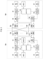
- a communication node shown in FIG. 3 may be a specific exemplary embodiment of the communication node shown in FIG. 2 .
- FIG. 3 is a block diagram illustrating a first exemplary embodiment of communication nodes performing communication.
- each of a first communication node 300a and a second communication node 300b may be a base station or UE.
- the first communication node 300a may transmit a signal to the second communication node 300b.
- a transmission processor 311 included in the first communication node 300a may receive data (e.g., data unit) from a data source 310.
- the transmission processor 311 may receive control information from a controller 316.
- the control information may include at least one of system information, RRC configuration information (e.g., information configured by RRC signaling), MAC control information (e.g., MAC CE), or PHY control information (e.g., DCI, SCI).
- the transmission processor 311 may generate data symbol(s) by performing processing operations (e.g., encoding operation, symbol mapping operation, etc.) on the data.
- the transmission processor 311 may generate control symbol(s) by performing processing operations (e.g., encoding operation, symbol mapping operation, etc.) on the control information.
- the transmission processor 311 may generate synchronization/reference symbol(s) for synchronization signals and/or reference signals.
- a Tx MIMO processor 312 may perform spatial processing operations (e.g., precoding operations) on the data symbol(s), control symbol(s), and/or synchronization/reference symbol(s).
- An output (e.g., symbol stream) of the Tx MIMO processor 312 may be provided to modulators (MODs) included in transceivers 313a to 313t.
- the modulator may generate modulation symbols by performing processing operations on the symbol stream, and may generate signals by performing additional processing operations (e.g., analog conversion operations, amplification operation, filtering operation, up-conversion operation, etc.) on the modulation symbols.
- the signals generated by the modulators of the transceivers 313a to 313t may be transmitted through antennas 314a to 314t.
- the search space information may include a CORESET identifier (ID) associated with a search space, a periodicity of PDCCH monitoring, and/or an offset of PDCCH monitoring.
- the periodicity and offset of PDCCH monitoring may each be indicated in slot units.
- the search space information may further include an index of a symbol where the PDCCH monitoring operation starts.
- the terminal may determine an SRS transmission power P SRS, b,f,c ( i, q s , l ) in an SRS transmission occasion ( i ) based on Equation 3 below.
- P SRS , b , f , c i q s l min P CMAX , f , c i , P O_SRS , b , f , c q s + 10 log 10 2 ⁇ ⁇ M SRS , b , f , c i + ⁇ SRS , b , f , c q s ⁇ PL b , f , c q d + h b , f , c i l dBm
- Each parameter in Equations 1 to 4 may be a parameter defined in the section 7 of TS 38.213.
- the terminal may consider a path loss to determine a transmission power for a UL channel/signal.
- PL may refer to the path loss.
- the terminal may determine compensation for the path loss based on a measurement result of a reference signal and may configure the transmission power considering the compensation for the path loss.
- a resource of the reference signal e.g., RS resource
- QCL information e.g., QCL state
- the terminal may transmit panel information (e.g., Tx panel information and/or Rx panel information) to the base station.
- panel information may include Tx panel information and/or Rx panel information.
- the base station may receive the panel information from the terminal.
- the panel information may be included in UE capability information (e.g., UE capability report) transmitted by the terminal.
- the base station may obtain the panel information of the terminal by receiving the UE capability information from the terminal.
- the panel information may include at least one of panel-specific maximum transmission power, the number of simultaneously available panels (e.g., the number of panels supporting STxMP), or combination(s) of simultaneously available panels (e.g., combination(s) of panels supporting STxMP).
- the panel information may include an index indicating panel-specific maximum transmission power, the number of simultaneously available panels, and/or combination(s) of simultaneously available panels.
- an index for each of the M panels may be configured.
- a panel #1, panel #2, ..., and panel #M may be configured.
- M may be a natural number.
- the terminal may transmit indexes of panels to the base station to notify the number and/or combination of simultaneously available panels.
- the terminal may notify the base station of the number n of available panels by transmitting values of M and M/2 n to the base station.
- M is 4, n may be configured as 0, 1, 2, 3, or 4.
- the terminal may notify the base station of information on combination(s) of two panels (e.g., index(es) for the combination(s)). For example, the terminal may transmit information on (panel #1, panel #4) and/or (panel #2, panel #3) to the base station. The terminal may transmit information on one or more combinations to the base station, and each of the one or more combinations may include two or more panels. The base station may receive the information on combination(s) of simultaneously available panels from the terminal. A distance between panels belonging to the same combination may be large, and the panels belonging to the same combination may have a low correlation.
- the base station may determine a combination (e.g., panels) used for communication based on the information on the combination(s) and locations of TRPs.
- the base station may transmit information on the determined combination and/or information (e.g., index(es), ID(s)) of TRP(s) communicating with the determined combination to the terminal through signaling.
- the base station may transmit mapping information of the determined combination and TRPs or mapping information of the determined panels and TRPs to the terminal.
- the terminal may receive, from the base station, information on the determined combination, information on TRP(s) communicating with the determined combination, mapping information of the determined combination and TRPs, and/or mapping information of the determined panels and TRPs.
- the terminal may determine (e.g., identify, configure) panels communicating with TRPs of the base station based on the information received from the base station.
- the terminal may determine a transmission power of each panel based on the following method(s) and may perform communication with the TRP(s) using the determined transmission powers.
- the terminal may determine a transmission power for each of multiple panels and may transmit UL channels/signals to STRP via the multiple panels using the determined transmission powers.
- the multiple panels of the terminal include a first panel and a second panel
- a first UL channel/signal may be transmitted via the first panel
- a second UL channel/signal may be transmitted via the second panel.
- the first UL channel/signal and the second UL channel/signal may be transmitted in the same time resource (e.g., the same symbol(s), the same slot) and different frequency resources.
- the terminal may determine (e.g., configure, allocate, adjust, control) the transmission power for each of multiple panels based on the following method(s).
- the following method(s) may be applied when a sum of the transmission powers (e.g., estimated transmission powers) for multiple panels is greater than the maximum transmission power of the terminal.
- the following method(s) may be performed to ensure that the sum of the transmission powers for multiple panels does not exceed the maximum transmission power of the terminal.
- the transmission power for each panel may be estimated considering reference signal(s) associated with a TCI state for a UL channel/signal allocated to each panel.
- the terminal may estimate the transmission power for each of multiple panels based on Equation 1, Equation 2, Equation 3, and/or Equation 4.
- the transmission power for each panel may be controlled (e.g., adjusted) based on the following method(s).
- the transmission power of the terminal may be allocated equally to panels regardless of priorities of the UL channels/signals transmitted via the panels of the terminal.
- Method #1 may be useful.
- communication performance in link(s) between panel(s) of the terminal and TRPs may be degraded.
- the terminal may measure link qualities between the panels of the terminal and TRPs.
- the link quality may be measured based on a reference signal received via a panel of the terminal.
- the terminal may allocate (e.g., configure) transmission powers differentially to the panels of the terminal considering the link qualities and may transmit UL channels/signals via the panels using the differentially allocated transmission powers.
- the terminal may allocate transmission powers differentially to the panels considering the link qualities between the panels and TRPs. Additionally, the terminal may select panel(s) for transmitting UL channel(s)/signal(s) considering the link qualities between the panels and TRPs and may transmit the UL channel(s)/signal(s) using the selected panel(s). Transmission powers may be allocated differentially to the selected panel(s) considering the link qualities. Therefore, the transmission power may be used efficiently.
- Detailed procedures according to Method #2 may be performed as follows.
- the terminal may allocate a transmission power to each of the selected panels.
- the selected panels may refer to available panels.
- the terminal may allocate the transmission power to each of the available panels based on Equation 5 or Equation 6.
- the terminal may allocate the transmission power differentially to each of the available panels considering the link qualities.
- the terminal may allocate the transmission power to each of the available panels regardless of the type of UL channel/signal (e.g., PUCCH, PUSCH, PRACH, SRS).
- the terminal may allocate the transmission power to each of the available panels regardless of the priority of the UL channel/signal.
- the terminal may allocate a basic transmission power to each of the available panels and may sequentially allocate the remaining transmission power starting from a panel with the best link quality. In this case, the terminal may allocate the remaining transmission power to the panel without exceeding the maximum transmission power of the panel. Alternatively, the terminal may sequentially allocate the remaining transmission power starting from a panel with the lowest link quality considering QoS.
- the basic transmission power may correspond to the minimum required link quality, and a sum of the basic transmission powers and the remaining transmission power may be equal to or less than the maximum transmission power of the terminal.
- Information on the basic transmission power may be configured for the terminal through signaling from the base station.
- a priority 1 may have the highest priority
- a priority 6 may have the lowest priority.
- [Table 2] Priority UL channel/signal 1 Transmission of a PRACH in a PCell 2 Transmision of a PUCCH with a high priority index, or transmission of a PUSCH with a high priority index 3
- transmission of a PUCCH including CSI or transmission of a PUSCH including CSI 5
- transmission of a PUSCH not including HARQ-ACK information or CSI transmission of a PUSCH for type-2 RA procedure
- transmission of a PUSCH in a PCell 6 Transmission of an SRS or transmission of a PRACH in a serving cell other than a PCell
- the terminal may allocate a portion of the remaining transmission power to the third panel. After allocating the transmission power to the third panel, the terminal may allocate a portion or all of the remaining transmission power to the first panel. In this case, the terminal may sequentially allocate the remaining transmission power to the third panel and the first panel so that a basic transmission power is allocated to each of the third panel and the first panel. For example, the terminal may allocate a basic transmission power to the third panel and the first panel, respectively, and may sequentially allocate the remaining transmission power starting from the third panel. According to Method #3, reception performance of a UL channel/signal with a high priority may be improved, and communication between the terminal and the base station (e.g., TRP) may be reliably performed.
- the base station e.g., TRP
- Method #4 may be a combination of Method #2 and Method #3.
- the terminal may allocate a transmission power to each panel considering both link qualities and priorities of UL channels/signals.
- the terminal may allocate a transmission power differentially to each panel based on priorities of UL channels/signals without considering link qualities. In this case, a panel with a good link quality (e.g., panel that can achieve good performance with a low transmission power) may not be used.
- the terminal may first allocate a transmission power to each panel based on Method #3. For example, the terminal may allocate a transmission power to the second panel for PRACH transmission first, then allocate a transmission power to the third panel for PUCCH transmission, and finally allocate a transmission power to the first panel for SRS transmission. After the transmission power is allocated to each panel based on Method #3, the terminal may adjust (e.g., control) the allocated transmission power for each panel based on Method #2. For example, the terminal may compare the measured link quality of each panel with the individual quality threshold (or common quality threshold).
- the terminal may transmit UL channels/signals via the multiple panels using the transmission powers allocated according to Method #3 without adjusting the transmission powers.
- the terminal may adjust the transmission power of the panel with a measured link quality lower than the individual quality threshold (or common quality threshold) to zero.
- the terminal may exclude the panel with a low measured link quality from UL channel/signal transmission.
- the terminal may configure the transmission power of the third panel to zero and may reallocate the transmission power originally allocated to the third panel to the second panel and/or the first panel. In this case, the terminal may transmit UL channels/signals using the second panel and the first panel.
- the third panel of the terminal may not be used for UL channel/signal transmission.
- Method #4 since the transmission power is allocated to each panel considering both link qualities and the priorities of the UL channels/signals, the transmission power of the terminal may be used efficiently.
- the terminal may determine a transmission power for each panel using one of Method #1, Method #2, Method #3, or Method #4.
- the base station may indicate to the terminal method(s) to be used for allocating the transmission powers through signaling.
- the base station may transmit configuration information for each method (e.g., detailed configuration information) to the terminal through signaling (e.g., system information signaling and/or RRC message signaling).
- the terminal may receive the configuration information for each method from the base station.
- the base station may transmit information indicating one of the configured methods (e.g., Method #1, Method #2, Method #3, or Method #4) to the terminal through signaling (e.g., MAC signaling and/or PHY signaling).
- the terminal may allocate a transmission power to each panel using the method indicated by the base station and may transmit UL channels/signals via multiple panels using the allocated transmission powers.
- the terminal may determine a transmission power for each of multiple panels and may transmit UL channels/signals to MTRP via the multiple panels using the determined transmission powers.
- the terminal may perform communication with each TRP using one or more panels. In other words, a TRP may be mapped to one or more panels of the terminal.
- transmission powers may be allocated based on the method described in Case #1 (e.g., Method #1, Method #2, Method #3, or Method #4).
- the method described in Case #1 (e.g., Method #1, Method #2, Method #3, or Method #4) may be applied to Case #2 on a TRP-by-TRP basis.
- the base station may be aware of information on multiple TRPs providing communication services to the terminal (e.g., terminal in the RRC connected state).
- the base station may transmit scheduling information for UL communication with multiple TRPs (e.g., scheduling information for CJT) to the terminal using control information (e.g., DCI).
- the terminal may receive the scheduling information and may perform UL communication with multiple TRPs based on the scheduling information.
- each of multiple TRPs may transmit scheduling information for UL communication (e.g., scheduling information for NCJT) to the terminal using control information (e.g., DCI).
- the terminal may receive the scheduling information and may perform UL communication with each of multiple TRPs based on the scheduling information.
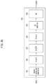
- FIG. 9 is a conceptual diagram illustrating a first exemplary embodiment of a UL channel/signal transmission method in an intra-cell MTRP environment.
- a base station may be connected to MTRP (e.g., TRP #1, TRP #2, ..., TRP #N), and the TRP #2 and TRP #N may belong to the same cell.
- N may be a natural number.
- the base station e.g., MTRP
- the base station may determine a beam pair and/or TRP-panel mapping by performing a beam management procedure with the terminal.
- the beam pair may refer to a beam pair between a transmission beam of a TRP and a reception beam of the terminal and/or a beam pair between a reception beam of the TRP and a transmission beam of the terminal.
- a panel #1 of the terminal may be mapped to the TRP #2, and a panel #2 of the terminal may be mapped to the TRP #N.
- the terminal may perform communication with the TRP #2 using the panel #1, and the terminal may perform communication with the TRP #N using the panel #2.
- the base station may comprehensively perform scheduling for DL communication and/or UL communication.
- the base station may transmit scheduling information for communication between MTRP and the terminal at once using single control information (e.g., single DCI).
- the base station may transmit scheduling information for communication between MTRP and the terminal using multiple pieces of control information (e.g., multiple DCIs), respectively.
- the number of multiple pieces of control information may be equal to the number of multiple TRPs performing communication with the terminal.
- the method described in Case #1 (e.g., Method #1, Method #2, Method #3, and/or Method #4) may be applied to the exemplary embodiment of FIG. 9 on a TRP-by-TRP basis.
- TRP(s) for DL communication and TRP(s) for UL communication may differ depending on presence of a reciprocity characteristic for the DL and UL channels.
- the terminal may transmit the same UL channel/signal or different UL channels/signals to MTRP. Since the maximum transmission power of the terminal is limited, at least one panel among all panels of the terminal may not be used for UL channel/signal transmission.
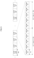
- FIG. 10 is a conceptual diagram illustrating a first exemplary embodiment of a UL channel/signal transmission method in an inter-cell MTRP environment.
- a base station #1 may be connected to MTRP (e.g., TRP #1_1, TRP #1_2, ..., TRP #1_N), and N may be a natural number.
- the base station #1 e.g., TRP #1_x
- TRP #1_x may determine a beam pair and/or TRP-panel mapping by performing a beam management procedure with the terminal.
- the beam pair may refer to a beam pair between a transmission beam of the TRP #1_x and a reception beam of the terminal and/or a beam pair between a reception beam of the TRP #1_x and a transmission beam of the terminal.
- TRP-panel mapping a panel #2 of the terminal may be mapped to the TRP #1_N of the base station #1. In other words, the terminal may perform communication with the TRP #1_N using the panel #2.
- a base station #2 may be connected to MTRP (e.g., TRP #2_1, TRP #2_2, ..., TRP #2_M), and M may be a natural number.
- the base station #2 e.g., TRP #2_x
- the beam pair may refer to a beam pair between a transmission beam of the TRP #2_x and a reception beam of the terminal and/or a beam pair between a reception beam of the TRP #2_x and a transmission beam of the terminal.
- the panel #1 of the terminal may be mapped to the TRP #2_M of base station #2. In other words, the terminal may perform communication with the TRP #2_M using the panel #1.
- the method(s) described in Case #1 may be applied to the exemplary embodiment of FIG. 10 on a TRP-by-TRP basis.
- Method #2 the terminal may determine available panel(s) based on link qualities after TRP-panel mapping is determined through the beam management procedure. In this case, TRP-panel mapping may be modified considering link qualities.
- the terminal may allocate (e.g., adjust, control) a transmission power to a panel mapped to each TRP considering a priority of a UL channel/signal to be transmitted to each TRP.
- the terminal may select available panel(s) based on link qualities and may allocate (e.g., adjust, control) a transmission power to each of the available panels considering a priority of a UL channel/signal.
- the panel #1 of the terminal may be mapped to the TRP #2_M of base station #2, and the panel #2 of the terminal may be mapped to the TRP #1_N of base station #1.
- the terminal may transmit a UL channel/signal using only one of the panel #1 and panel #2.
- the terminal may transmit the UL channel/signal to the TRP #1_N connected to the base station #1 using only the panel #2.
- the TRP #2_M connected to the base station #2 may not receive the UL channel/signal from the terminal.
- the base station #2 may transmit information indicating that the UL channel/signal from the terminal has not been received to the base station #1.
- a programmable logic device such as a field-programmable gate array may be used to perform some or all of functions of the methods described herein.
- the field-programmable gate array may be operated with a microprocessor to perform one of the methods described herein. In general, the methods are preferably performed by a certain hardware device.
Landscapes
- Engineering & Computer Science (AREA)
- Computer Networks & Wireless Communication (AREA)
- Signal Processing (AREA)
- Quality & Reliability (AREA)
- Power Engineering (AREA)
- Databases & Information Systems (AREA)
- Mobile Radio Communication Systems (AREA)
Applications Claiming Priority (2)
| Application Number | Priority Date | Filing Date | Title |
|---|---|---|---|
| KR20220142907 | 2022-10-31 | ||
| PCT/KR2023/016727 WO2024096437A1 (ko) | 2022-10-31 | 2023-10-26 | Mtrp를 지원하는 통신 시스템에서 상향링크 전력 제어의 방법 및 장치 |
Publications (1)
| Publication Number | Publication Date |
|---|---|
| EP4580268A1 true EP4580268A1 (de) | 2025-07-02 |
Family
ID=90930991
Family Applications (1)
| Application Number | Title | Priority Date | Filing Date |
|---|---|---|---|
| EP23886133.0A Pending EP4580268A1 (de) | 2022-10-31 | 2023-10-26 | Verfahren und vorrichtung zur uplink-leistungssteuerung in einem kommunikationssystem mit mprp-unterstützung |
Country Status (4)
| Country | Link |
|---|---|
| EP (1) | EP4580268A1 (de) |
| KR (1) | KR20240061612A (de) |
| CN (1) | CN120188538A (de) |
| WO (1) | WO2024096437A1 (de) |
Family Cites Families (5)
| Publication number | Priority date | Publication date | Assignee | Title |
|---|---|---|---|---|
| US10856237B2 (en) * | 2019-02-14 | 2020-12-01 | Ofinno, Llc | Power control with multiple panels in a radio system |
| US12192910B2 (en) * | 2019-03-28 | 2025-01-07 | Lg Electronics Inc. | Method for transmitting uplink signal in wireless communication system, and apparatus therefor |
| CN115669098A (zh) * | 2020-03-18 | 2023-01-31 | 康卡斯特有线通信有限责任公司 | 用于无线通信的暴露检测和报告 |
| EP4140203A4 (de) * | 2020-04-24 | 2024-01-10 | Qualcomm Incorporated | Leistungsteilung für eine uplink-übertragung unter verwendung mehrerer antennenpaneele |
| WO2022027306A1 (en) * | 2020-08-05 | 2022-02-10 | Apple Inc. | Systems and methods for user equipment (ue) selection from among asymmetric uplink (ul) antenna panels |
-
2023
- 2023-10-26 WO PCT/KR2023/016727 patent/WO2024096437A1/ko not_active Ceased
- 2023-10-26 EP EP23886133.0A patent/EP4580268A1/de active Pending
- 2023-10-26 CN CN202380075817.2A patent/CN120188538A/zh active Pending
- 2023-10-26 KR KR1020230144504A patent/KR20240061612A/ko active Pending
Also Published As
| Publication number | Publication date |
|---|---|
| CN120188538A (zh) | 2025-06-20 |
| KR20240061612A (ko) | 2024-05-08 |
| WO2024096437A1 (ko) | 2024-05-10 |
Similar Documents
| Publication | Publication Date | Title |
|---|---|---|
| US11395319B2 (en) | Method for differentiating multiple physical downlink shared channel (PDSCH) transmission schemes | |
| US20120275411A1 (en) | Apparatus for performing comp communication using a precoded sounding reference signal, and method for same | |
| US12556331B2 (en) | Method for transmitting SRS for plurality of uplink bands in wireless communication system, and apparatus therefor | |
| US20250070935A1 (en) | System and method for providing additional dm-rs ports for 5g mu-mimo transmission | |
| KR20240164429A (ko) | 단일 trp와 다중 trp 간의 스위칭의 방법 및 장치 | |
| EP4580268A1 (de) | Verfahren und vorrichtung zur uplink-leistungssteuerung in einem kommunikationssystem mit mprp-unterstützung | |
| EP4626117A1 (de) | Verfahren und vorrichtung zur aktivierung/deaktivierung von tci in einem mtrp-system | |
| EP4694490A1 (de) | Verfahren und vorrichtung zur anzeige des tci-status in einem kommunikationssystem | |
| EP4664786A1 (de) | Verfahren und vorrichtung zur strahlbestimmung in einem kommunikationssystem | |
| EP4586535A1 (de) | Verfahren und vorrichtung zum senden und empfangen von pt-rs in einem kommunikationssystem | |
| US20250317186A1 (en) | Method and device for beam recovery in mobile communication system of mtrp environment | |
| EP4675937A1 (de) | Verfahren und vorrichtung zur uplink-signalübertragung in einem kommunikationssystem | |
| EP4580078A1 (de) | Verfahren und vorrichtung zur vereinheitlichten tci-konfiguration in einem kommunikationssystem mit mehreren sende- und empfangspunkten | |
| US20250373375A1 (en) | Method and device for data transmission and reception in mobile communication system in mtrp environment | |
| EP4604654A1 (de) | Verfahren und vorrichtung zur ressourcenzuweisung an mehreren sende- und empfangspunkten in einem drahtloskommunikationssystem | |
| US20260046005A1 (en) | Method and device for beam management in wireless communication system | |
| KR20250063232A (ko) | 통신 시스템에서 mpe 보고의 방법 및 장치 | |
| KR20250023294A (ko) | 다중 trp 시스템에서 빔 스위칭의 방법 및 장치 | |
| KR20250047199A (ko) | 다중 trp 시스템에서 빔 관리의 방법 및 장치 | |
| KR20250063234A (ko) | 통신 시스템에서 상향링크 채널의 전송 방법 및 장치 | |
| KR20250023926A (ko) | Trp 환경에서 상향링크 데이터 전송 방법 및 장치 | |
| KR20250046199A (ko) | 다중 trp 통신에서 trp 스위칭의 방법 및 장치 | |
| KR20250023271A (ko) | 다중 trp 시스템에서 데이터 채널의 송수신 방법 및 장치 | |
| KR20240128623A (ko) | 통신 시스템에서 다중 송수신점을 이용한 통신 방법 및 장치 | |
| KR20250063765A (ko) | 무선 통신 시스템에서 다중 송수신점 환경을 위한 전력 헤드룸 보고를 송신하기 위한 방법 및 장치 |
Legal Events
| Date | Code | Title | Description |
|---|---|---|---|
| STAA | Information on the status of an ep patent application or granted ep patent |
Free format text: STATUS: THE INTERNATIONAL PUBLICATION HAS BEEN MADE |
|
| PUAI | Public reference made under article 153(3) epc to a published international application that has entered the european phase |
Free format text: ORIGINAL CODE: 0009012 |
|
| STAA | Information on the status of an ep patent application or granted ep patent |
Free format text: STATUS: REQUEST FOR EXAMINATION WAS MADE |
|
| 17P | Request for examination filed |
Effective date: 20250328 |
|
| AK | Designated contracting states |
Kind code of ref document: A1 Designated state(s): AL AT BE BG CH CY CZ DE DK EE ES FI FR GB GR HR HU IE IS IT LI LT LU LV MC ME MK MT NL NO PL PT RO RS SE SI SK SM TR |
|
| DAV | Request for validation of the european patent (deleted) | ||
| DAX | Request for extension of the european patent (deleted) |