EP4580266A1 - Endgerät, drahtloskommunikationsverfahren und basisstation - Google Patents
Endgerät, drahtloskommunikationsverfahren und basisstation Download PDFInfo
- Publication number
- EP4580266A1 EP4580266A1 EP23857042.8A EP23857042A EP4580266A1 EP 4580266 A1 EP4580266 A1 EP 4580266A1 EP 23857042 A EP23857042 A EP 23857042A EP 4580266 A1 EP4580266 A1 EP 4580266A1
- Authority
- EP
- European Patent Office
- Prior art keywords
- information
- transmission
- tci
- trp
- power control
- Prior art date
- Legal status (The legal status is an assumption and is not a legal conclusion. Google has not performed a legal analysis and makes no representation as to the accuracy of the status listed.)
- Pending
Links
Images


Classifications
-
- H—ELECTRICITY
- H04—ELECTRIC COMMUNICATION TECHNIQUE
- H04W—WIRELESS COMMUNICATION NETWORKS
- H04W52/00—Power management, e.g. Transmission Power Control [TPC] or power classes
- H04W52/04—Transmission power control [TPC]
- H04W52/30—Transmission power control [TPC] using constraints in the total amount of available transmission power
- H04W52/32—TPC of broadcast or control channels
- H04W52/325—Power control of control or pilot channels
-
- H—ELECTRICITY
- H04—ELECTRIC COMMUNICATION TECHNIQUE
- H04B—TRANSMISSION
- H04B17/00—Monitoring; Testing
- H04B17/30—Monitoring; Testing of propagation channels
- H04B17/309—Measuring or estimating channel quality parameters
- H04B17/347—Path loss
-
- H—ELECTRICITY
- H04—ELECTRIC COMMUNICATION TECHNIQUE
- H04W—WIRELESS COMMUNICATION NETWORKS
- H04W52/00—Power management, e.g. Transmission Power Control [TPC] or power classes
- H04W52/04—Transmission power control [TPC]
- H04W52/18—TPC being performed according to specific parameters
- H04W52/24—TPC being performed according to specific parameters using SIR [Signal to Interference Ratio] or other wireless path parameters
- H04W52/242—TPC being performed according to specific parameters using SIR [Signal to Interference Ratio] or other wireless path parameters taking into account path loss
Definitions
- control of reception processing for example, at least one of reception, demapping, demodulation, and decoding
- transmission processing for example, at least one of transmission, mapping, precoding, modulation, and coding
- TCI state transmission configuration indication state
- the TCI state is information related to quasi-co-location (QCL) of the signal/channel, and may be referred to as a spatial reception parameter, spatial relation information, or the like.
- the TCI state may be configured for the UE for each channel or for each signal.
- the spatial reception parameter may correspond to a receive beam of the UE (for example, a receive analog beam), and the beam may be identified based on spatial QCL.
- the QCL (or at least one element in the relationship of QCL) in the present disclosure may be interpreted as sQCL (spatial QCL).
- QCL types For the QCL, a plurality of types (QCL types) may be defined. For example, four QCL types A to D may be provided, which have a different parameter(s) (or a parameter set(s)) that can be assumed to be the same.
- a case that the UE assumes that a given control resource set (CORESET), channel, or reference signal is in a relationship of specific QCL (for example, QCL type D) with another CORESET, channel, or reference signal may be referred to as QCL assumption.
- CORESET control resource set
- QCL QCL type D
- the UE may determine at least one of a transmit beam (Tx beam) and a receive beam (Rx beam) of the signal/channel, based on the TCI state or the QCL assumption of the signal/channel.
- Tx beam transmit beam
- Rx beam receive beam
- the TCI state may be, for example, information related to QCL between a channel as a target (in other words, a reference signal (RS) for the channel) and another signal (for example, another RS).
- RS reference signal
- the TCI state may be configured (indicated) by higher layer signaling or physical layer signaling, or a combination of these.
- a channel for which the TCI state or spatial relation is configured (specified) may be, for example, at least one of a downlink shared channel (Physical Downlink Shared Channel (PDSCH)), a downlink control channel (Physical Downlink Control Channel (PDCCH)), an uplink shared channel (Physical Uplink Shared Channel (PUSCH)), and an uplink control channel (Physical Uplink Control Channel (PUCCH)).
- PDSCH Physical Downlink Shared Channel
- PDCCH Physical Downlink Control Channel
- PUSCH Physical Uplink Shared Channel
- PUCCH Physical Uplink Control Channel
- the RS to have a QCL relationship with the channel may be, for example, at least one of a synchronization signal block (SSB), a channel state information reference signal (CSI-RS), a reference signal for measurement (Sounding Reference Signal (SRS)), a CSI-RS for tracking (also referred to as a Tracking Reference Signal (TRS)), and a reference signal for QCL detection (also referred to as a QRS).
- SSB synchronization signal block
- CSI-RS channel state information reference signal
- SRS Sounding Reference Signal
- TRS Tracking Reference Signal
- QRS reference signal for QCL detection
- the SSB is a signal block including at least one of a primary synchronization signal (PSS), a secondary synchronization signal (SSS), and a broadcast channel (Physical Broadcast Channel (PBCH)).
- PSS primary synchronization signal
- SSS secondary synchronization signal
- PBCH Physical Broadcast Channel
- the SSB may be referred to as an SS/PBCH block.
- An RS of QCL type X in a TCI state may mean an RS in a relationship of QCL type X with (a DMRS of) a given channel/signal, and this RS may be referred to as a QCL source of QCL type X in the TCI state.
- a UE can be configured with a list of up to M TCI-State (TCI state) configurations in a higher layer parameter PDSCH-Config for decoding of a PDSCH, according to a detected PDCCH with DCI targeting the UE and a given serving cell.
- TCI state TCI-State
- M depends on UE capability maxNumberConfiguredTCIstatesPerCC.
- Each TCI-State includes a parameter for configuration of a QCL relationship between one or two downlink reference signals and a DMRS port of the PDSCH, a DMRS port of the PDCCH, or a CSI-RS port of a CSI-RS resource.
- the QCL relationship is configured by a higher layer parameter qcl-Type1 for a first DL RS and a higher layer parameter qcl-Type2 for a second DL RS (if configured).
- a plurality of QCL types are not the same irrespective of whether reference is reference to the same DL RS or reference to different DL RSs.
- the QCL type corresponding to each DL RS is given by a higher layer parameter qcl-Type in QCL-Info and takes a value corresponding to one of the following.
- TCI-State associates one or two DL reference signals (RSs) with a corresponding QCL type. If an additional physical cell identifier (PCI) is configured for the RS(s), the same value is configured for both of the DL RSs.
- PCI physical cell identifier
- a unified TCI framework may indicate a common beam (common TCI state) and apply the common beam to all the UL and DL channels instead of defining a TCI state or a spatial relation for each channel as in Rel. 15, or apply a common beam for UL to all the UL channels while applying a common beam for DL to all the DL channels.
- the UE may assume the same TCI state (joint TCI state, joint TCI pool, joint common TCI pool, joint TCI state set) for UL and DL.
- the UE may assume respective different TCI states (separate TCI states, separate TCI pools, UL separate TCI pool and DL separate TCI pool, separate common TCI pools, UL common TCI pool and DL common TCI pool) for UL and DL.
- default UL and DL beams may be aligned.
- a default TCI state of a PDSCH may be updated to match to a default UL beam (spatial relation).
- a common beam / unified TCI state may be indicated from the same TCI pool (joint common TCI pool, joint TCI pool, set) for both UL and DL.
- X (>1) TCI states may be activated by a MAC CE.
- UL/DL DCI may select one from the X active TCI states.
- the selected TCI state may be applied to channels/RSs of both UL and DL.
- the TCI pool (set) may be a plurality of TCI states configured by an RRC parameter or a plurality of TCI states (active TCI states, active TCI pool, set) activated by a MAC CE among the plurality of TCI states configured by the RRC parameter.
- Each TCI state may be a QCL type A/D RS.
- the number of TCI states corresponding to each of one or more TRPs may be defined.
- the number N ( ⁇ 1) of TCI states to be applied to a UL channel/RS (UL TCI states) and the number M ( ⁇ 1) of TCI states to be applied to a DL channel/RS (DL TCI state) may be defined.
- At least one of N and M may be notified/configured/indicated to a UE via higher layer signaling/physical layer signaling.
- this may mean that X TCI states (corresponding to X TRPs) common to UL and DL (joint TCI states) are notified/configured/indicated to a UE.
- this may mean that X UL TCI state(s) (corresponding to X TRP(s)) and Y DL TCI state(s) (corresponding to Y TRP(s)) (i.e., separate TCI states) are notified/configured/indicated to a UE.
- this may mean that one TCI state common to DL and UL for a single TRP is notified/configured/indicated to a UE (joint TCI state for a single TRP).
- this may mean that one UL TCI state and one DL TCI state for a single TRP are separately notified/configured/indicated to a UE (separate TCI states for a single TRP).
- this may mean that a plurality of (two) TCI states common to UL and DL for a plurality of (two) TRPs are notified/configured/indicated to a UE (joint TCI states for a plurality of TRPs).
- f b,f,c (i,l) is a value based on the TPC command with the power control adjustment state index l of the active UL BWP in the carrier f of the serving cell c and the transmission occasion i (for example, a power control adjustment state, an accumulated TPC command value, or a closed loop value).
- l may be referred to as a closed loop index.
- the UE may calculate PL b,f,c (q d ) by using an RS resource, based on an SSB used for obtaining a Master Information Block (MIB).
- MIB Master Information Block
- the set of RS resource indices may include one of or both a set of SS/PBCH block indices and a set of CSI-RS resource indices.
- the UE may identify an RS resource index q d in the set of RS resource indices.
- the UE may use the same RS resource index q d as that for corresponding PRACH transmission.
- RAR Random Access Response
- the UE may obtain mapping between a set of values for an SRI field in DCI format 0_1 and a set of ID value(s) of the pathloss reference RS(s) by higher layer signaling (for example, sri-PUSCH-PowerControl-Id in SRI-PUSCH-PowerControl).
- the UE may determine the RS resource index q d , based on the ID of the pathloss reference RS mapped in the SRI field value in DCI format 0_1 for scheduling the PUSCH.
- the UE may use the same RS resource index q d as that for PUCCH transmission in the PUCCH resource.
- the UE may use the RS resource index q d with the pathloss reference RS ID of zero.
- an RS resource index q d may be provided to the UE by a pathloss reference index (for example, pathlossReferenceIndex) in the given parameter.
- the UE may determine the RS resource index q d , based on the value of the ID of the pathloss reference RS mapped in the SRI field in the DCI format for activating the PUSCH transmission.
- the UE may determine the RS resource index q d with the pathloss reference RS ID of zero.
- a transmission power of a PUCCH is controlled based on a TPC command (also referred to as a value, an increase/decrease value, a correction value, an indication value, and the like) indicated by the value of a given field (also referred to as a TPC command field, a first field, and the like) in DCI.
- a TPC command also referred to as a value, an increase/decrease value, a correction value, an indication value, and the like
- a given field also referred to as a TPC command field, a first field, and the like
- a transmission power (P PUCCH,b,f,c (i,q u ,q d ,l)) of a PUCCH in a PUCCH transmission occasion (also referred to as a transmission period and the like) i for the active UL BWP b in the carrier f of the serving cell c may be expressed by equation (2) below.
- P PUCCH , b , f , c i q u q d l : min P CMAX , f , c i , P O_PUCCH , b , f , c q u + 10 log 10 2 ⁇ ⁇ M RB , b , f , c PUSCH i + PL b , f , c q d + ⁇ F_PUCCH F + ⁇ TF , b , f , c i + g b , f , c i l dBm
- the power control adjustment state may be referred to as a PUCCH power control adjustment state, a first or second state, and the like.
- the PUCCH transmission occasion i is a given period in which a PUCCH is transmitted and may be constituted of one or more symbols, one or more slots, or the like, for example.
- P CMAX,f,c (i) is, for example, a transmission power (also referred to as a maximum transmission power, a UE maximum output power, and the like) of a user terminal configured for the carrier f of the serving cell c in the transmission occasion i.
- P O_PUCCH,b,f,c (q u ) is, for example, a parameter related to a target received power configured for the active UL BWP b in the carrier f of the serving cell c in the transmission occasion i (for example, also referred to as a parameter related to a transmission power offset, a transmission power offset P0, or a target received power parameter, and the like).
- M PUCCH RB,b,f,c (i) is, for example, the number of resource blocks (bandwidth) allocated to a PUCCH for the transmission occasion i in the active UL BWP b in the carrier f of the serving cell c with subcarrier spacing ⁇ .
- PL b,f,c (q d ) is, for example, pathloss calculated by the user terminal by using the index q d of a reference signal (pathloss reference RS, DL-RS for pathloss measurement, PUCCH-PathlossReferenceRS) for downlink BWP associated with the active UL BWP b in the carrier f of the serving cell c.
- ⁇ F_PUCCH (F) is a higher layer parameter given for each PUCCH format.
- ⁇ TF,b,f,c (i) is a transmission power adjustment component (offset) for the UL BWP b in the carrier f of the serving cell c.
- g b,f,c (i,l) is a value based on the TPC command with the power control adjustment state index l of the active UL BWP in the carrier f of the serving cell c and the transmission occasion i (for example, a power control adjustment state, an accumulated TPC command value, a closed loop value, and a PUCCH power adjustment state).
- the UE may obtain mapping between a PUCCH spatial relation information ID (pucch-SpatialRelationInfoId) value and a closed loop index (closedLoopIndex, power adjustment state index l), by an index provided by ID of P0 for PUCCH (p0-PUCCH-Id in p0-Set in PUCCH-PowerControl in PUCCH-Config).
- a PUCCH spatial relation information ID prcch-SpatialRelationInfoId
- closed loop index closedLoopIndex, power adjustment state index l
- the UE may determine the value of the closed loop index providing the value l, via the link to the corresponding ID of P0 for PUCCH.
- the UE may determine the value l from a value q u , based on the PUCCH spatial relation information associated with the ID of P0 for PUCCH corresponding to q u and the closed loop index value corresponding to l.
- q u may be the ID of P0 for PUCCH (p0-PUCCH-Id) indicating P0 for PUCCH (P0-PUCCH) in a P0 set for PUCCH (p0-Set).
- transmission power (P SRS,b,f,c (i,q s ,l)) of an SRS in a transmission occasion (also referred to as a transmission period and the like) i of a reference signal for measurement (Sounding Reference Signal (SRS)) for the active UL BWP b in the carrier f of the serving cell c may be expressed by equation (3) below.
- the power control adjustment state may be referred to as an SRS power control adjustment state, a value based on a TPC command, an accumulated TPC command value, a closed loop value, a first or second state, and the like.
- l may be referred to as a closed loop index.
- the SRS transmission occasion i is a given period in which an SRS is transmitted and may be constituted of one or more symbols, one or more slots, or the like, for example.
- P SRS , b , f , c i q s l min P CMAX , f , c i , P O_SRS , b , f , c q s + 10 log 10 2 ⁇ ⁇ M SRS , b , f , c i + ⁇ SRS , b , f , c q s ⁇ PL b , f , c q d + h b , f , c i l dBm
- P CMAX,f,c (i) is, for example, a UE maximum output power for the carrier f of the serving cell c in the SRS transmission occasion i.
- P O_SRS,b, f,c (q s ) is a parameter related to a target received power provided by p0 (also referred to as a parameter related to a transmission power offset, a transmission power offset P0, a target received power parameter, and the like, for example) for the active UL BWP b in the carrier f of the serving cell c and an SRS resource set q s (provided by SRS-ResourceSet and SRS-ResourceSetId).
- the plurality of PUCCHs may fully/partially overlap in the time domain.
- the inventors of the present invention came up with the idea of a method of appropriately performing power control of UL transmission also in operation related to a unified TCI state or operation in STxMP UL transmission.
- radio resource control RRC
- RRC parameter RRC parameter
- RRC message RRC message
- IE information element
- CE Medium Access Control control element
- MAC Control Element CE
- update command an activation/deactivation command, and the like
- the higher layer signaling may be, for example, any one or combinations of Radio Resource Control (RRC) signaling, Medium Access Control (MAC) signaling, broadcast information, and the like.
- RRC Radio Resource Control
- MAC Medium Access Control
- the MAC signaling may use, for example, a MAC control element (MAC CE), a MAC Protocol Data Unit (PDU), or the like.
- the broadcast information may be, for example, a master information block (MIB), a system information block (SIB), minimum system information (Remaining Minimum System Information (RMSI)), other system information (OSI), or the like.
- MIB master information block
- SIB system information block
- RMSI Remaining Minimum System Information
- OSI system information
- the physical layer signaling may be, for example, downlink control information (DCI), uplink control information (UCI), or the like.
- DCI downlink control information
- UCI uplink control information
- an index, an identifier (ID), an indicator, a resource ID, and the like may be interchangeably interpreted.
- a sequence, a list, a set, a group, a cluster, a subset, and the like may be interchangeably interpreted.
- a panel Identifier (ID) and a panel may be interchangeably interpreted.
- ID a TRP ID and a TRP, a CORESET group ID and a CORESET group, and the like may be interchangeably interpreted.
- a TRP a transmission point, a panel, a DMRS port group, a CORESET pool, and one of two TCI states associated with one codepoint of a TCI field may be interchangeably interpreted.
- transmission/reception of a channel/signal using a single TRP may be interpreted as TCI states (joint/separate/indicated TCI states) being equal in the transmission/repetition of the channel/signal (for example, NCJT/CJT/repetition) or the number of TCI states (joint/separate/indicated TCI states) is one in the transmission/reception of the channel/signal (for example, NCJT/CJT/repetition).
- Transmission/reception of a channel/signal using a single TRP may be interpreted as TCI states (joint/separate/indicated TCI states) being different in the transmission repetition of the channel/signal (for example, NCJT/CJT/repetition) or the number of different TCI states (joint/separate/indicated TCI states) is more than one (for example, two) in the transmission/reception of the channel/signal (for example, NCJT/CJT/repetition).
- a single (one) TRP, a single-TRP system, single-TRP transmission, and a single PDSCH may be interchangeably interpreted.
- multi-TRP multiple TRPs
- a multi-TRP system, multi-TRP transmission, and multi-PDSCH may be interchangeably interpreted.
- single-DCI single-DCI, a single PDCCH, single-DCI based multi-TRP, two TCI states on at least one TCI codepoint being activated, at least one codepoint of a TCI field being mapped to two TCI states, a specific index (for example, a TRP index, a CORESET pool index, or an index corresponding to a TRP) being configured for a specific channel/CORESET may be interchangeably interpreted.
- a single TRP a channel/signal using a single TRP, a channel using one TCI state/spatial relation, multi-TRP being not enabled by RRC/DCI, a plurality of TCI states/spatial relations being not enabled by RRC/DCI, and one CORESET pool index (CORESETPoolIndex) value being not configured for any CORESET and any codepoint of a TCI field being not mapped to two TCI states
- CORESETPoolIndex CORESET pool index
- multi-TRP a channel/signal using multi-TRP, a channel using a plurality of TCI states/spatial relations, multi-TRP being enabled by RRC/DCI, a plurality of TCI states/spatial relations being enabled by RRC/DCI, and at least one of single-DCI based multi-TRP and multi-DCI based multi-TRP may be interchangeably interpreted.
- multi-DCI based multi-TRP one CORESET pool index (CORESETPoolIndex) value being configured for a CORESET
- CORESETPoolIndex a plurality of specific indices (for example, TRP indices, and CORESET pool indices, or indices corresponding to TRPs) being configured for specific channels/CORESETs
- single DCI sDCI
- PDCCH Physical Downlink Control Channel
- multi-TRP system based on single DCI
- sDCI-based MTRP multi-TRP system based on single DCI
- sDCI-based MTRP multi-TRP system based on single DCI
- sDCI-based MTRP multi-TRP system based on single DCI
- sDCI-based MTRP multi-TRP system based on single DCI
- two TCI states in at least one TCI codepoint being activated may be interchangeably interpreted.
- multi-DCI multi-PDCCH
- a multi-TRP system based on multi-DCI mDCI-based MTRP
- beam indication DCI, a beam indication MAC CE, and beam indication DCI/MAC CE may be interchangeably interpreted.
- indication related to an indication TCI state for a UE may be performed by using at least one of DCI and a MAC CE.
- repetition, repetition transmission, and repetition reception may be interchangeably interpreted.
- a channel, a signal, and a channel/signal may be interchangeably interpreted.
- a DL channel, a DL signal, a DL signal/channel, transmission/reception of a DL signal/channel, DL reception, and DL transmission may be interchangeably interpreted.
- a UL channel, a UL signal, a UL signal/channel, transmission/reception of a UL signal/channel, UL reception, and UL transmission may be interchangeably interpreted.
- application of a TCI state/QCL assumption to each channel/signal/resource may mean application of a TCI state/QCL assumption to transmission/reception of each channel/signal/resource.
- a first TCI state may correspond to a first TRP.
- a second TCI state may correspond to a second TRP.
- an n-th TCI state may correspond to an n-th TRP.
- a value (for example, 0) of a first CORESET pool index, a value (for example, 1) of a first TRP index, and a first TCI state (first DL/UL (joint/separate) TCI state) may correspond to each other.
- a value (for example, 1) of a second CORESET pool index, a value (for example, 2) of a second TRP index, and a second TCI state (second DL/UL (joint/separate) TCI state) may correspond to each other.
- the number of TRPs may be three or more (multiple), and each embodiment may be applied so as to correspond to the number of TRPs.
- at least one of N and M may be a number larger than two.
- reception of a DL signal (PDSCH/PDCCH) using an SFN may mean reception by using the same time/frequency resource and/or of the same data (PDSCH)/control information (PDCCH) from a plurality of transmission/reception points.
- Reception of a DL signal using an SFN may mean reception by using the same time/frequency resource and/or of the same data/control information by using a plurality of TCI states/spatial domain filters/beams/QCLs.
- a default power control setting, a default power control parameter, a power control parameter used when no UL TCI state/joint TCI state is configured, a power control setting used when a UL TCI state/joint TCI state is configured, a UL transmission power configuration, a UL transmission power parameter, a power control setting, a power control parameter, and the like may be interchangeably interpreted.
- a UE may control transmission power of UL transmission, based on a plurality of power control settings (PC settings).
- PC settings power control settings
- the two power control settings may be a first UL power control parameter (power control setting) and a second UL power control parameter (power control setting), for example.
- a first UL power control parameter for example, uplink-powerControl-r17
- a second UL power control parameter for example, uplink-powerControl-TRP2-r18
- a UE-specific UL BWP configuration for example, BWP-UplinkDedicated
- These parameters may both indicate UL power control parameter IDs (Uplink-powerControlId-r17).
- a first UL power control parameter (for example, uplink-powerControl-r17) may be used for transmission power control for a first TRP.
- a second UL power control parameter (for example, uplink-powerControl-TRP2-r18) may be used for transmission power control for a second TRP.
- the first UL power control parameter (for example, uplink-powerControl-r17) may be used.
- the first power control setting may refer to a power control setting provided by a parameter defined in Rel. 17.
- the second power control setting may refer to a power control setting provided by a parameter defined in Rel. 18.
- uplink-powerControl-r17 and a first/second UL power control parameter may be included in a UE-specific UL BWP configuration (for example, BWP-UplinkDedicated) (structure B).
- the first/second UL power control parameter may indicate a plurality of (for example, two) UL power control parameter IDs (for example, Uplink-powerControlId-r17).
- the first/second UL power control parameter (for example, uplink-powerControl-MTRP-r18) may be a list including a plurality of (for example, two) UL power control parameter IDs (for example, Uplink-powerControlId-r17).
- a multi-TRP PUSCH/PUCCH and a single-TRP PUSCH/PUCCH may be dynamically switched (for example, by using (a specific field) of DCI).
- the UE may determine a correspondence/mapping between the first/second UL power control parameter and the first/second TRP, based on specific information/condition/method.
- specific information/condition/method will be described in detail in first to seventh embodiments below.
- correspondences/mapping between a plurality of (for example, two) power control settings and UL transmission may be the same as correspondences/mapping between a plurality of (for example, two) TCI states and UL transmission (for example, a PUSCH/PUCCH/SRS).
- the correspondence/mapping between a plurality of (for example, two) TCI states and UL transmission may be determined/configured based on a specific method/condition.
- the specific method/condition may be a method/condition defined in Rel. 18, for example.
- the plurality of (for example, two) TCI states may be a plurality of (for example, two) indicated TCI states (UL TCI states/joint (DL-UL) TCI states).
- the plurality of (first/second) TCI states may be TCI states activated by a MAC CE and mapped to a DCI codepoint(s) (TCI field codepoint(s)).
- the plurality of (first/second) TCI states may be TCI states corresponding to specific TCI state IDs.
- the first TCI state may be a TCI state corresponding to a lower (or higher) TCI state ID.
- the second TCI state may be a TCI state corresponding to a higher (lower) TCI state ID.
- the first TCI state may be a TCI state associated with a lower (or higher) CORESET pool index.
- the second TCI state may be a TCI state associated with a higher (or lower) CORESET pool index.
- This embodiment relates to PUSCH.
- the PUSCH of this embodiment may be PUSCHs (repetition) using multi-TRP, for example.
- This embodiment is broadly categorized into options 2-0 to 2-3 below.
- a UE/base station may follow at least one of options 2-0 to 2-3 below.
- a plurality of (two) power control settings need not be applied to PUSCHs (repetition) using multi-TRP.
- the UE need not apply a plurality of (two) power control settings to PUSCHs (repetition) using multi-TRP.
- whether or not to apply a plurality of (two) power control settings to PUSCHs (repetition) using multi-TRP may be determined/configured for each CC/cell/BWP/band.
- a first power control setting may correspond to a first (codebook (CB)/non-codebook (NCB)) SRS resource set.
- a second power control setting may correspond to a second (CB/NCB) SRS resource set.
- the first (CB/NCB) SRS resource set may be an SRS resource set corresponding to a lower (or higher) SRS resource set ID.
- the second (CB/NCB) SRS resource set may be an SRS resource set corresponding to a higher (or lower) SRS resource set ID.
- the UE may determine, for multi-TRP PUSCHs, that a correspondence/mapping between the first/second power control setting and a PUSCH (repetition) is the same as a correspondence/mapping between a first/second SRS resource set and a PUSCH (repetition).
- the UE may determine to use the first/second power control setting for the PUSCH.
- the correspondence/mapping between the first/second SRS resource set and a PUSCH may be the same as the correspondence/mapping defined in Rel. 17.
- a first power control setting may correspond to a first SRI field.
- a second power control setting may correspond to a second SRI field.
- the UE may determine, for multi-TRP PUSCHs, that a correspondence/mapping between the first/second power control setting and a PUSCH (repetition) may be the same as a correspondence/mapping between a first/second SRI field and a PUSCH (repetition).
- the UE may determine to use the first/second power control setting for the PUSCH.
- the correspondence/mapping between the first/second SRI field and a PUSCH may be the same as the correspondence/mapping defined in Rel. 17.
- a correspondence/mapping between a first/second power setting and a PUSCH may be defined.
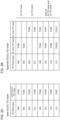
- the UE may apply first power control to a plurality of (for example, all) PUSCHs (repetition).
- the UE may apply second power control to a plurality of (for example, all) PUSCHs (repetition).
- the UE may apply the first power control setting to a first repetition and apply the second power control setting to a second repetition.
- the UE may apply the first power control setting to the first repetition and apply the second power control setting to the second repetition.
- the UE may apply the same mapping pattern to a remaining repetition(s).
- the UE may apply the first power control setting to a plurality of (for example, first and second) repetitions and apply the second power control setting to a plurality of other (for example, third and fourth) repetitions.
- the UE may apply the same mapping pattern to a remaining repetition(s).
- the UE may apply the second power control setting to a first repetition and apply the first power control setting to a second repetition.
- the UE may apply the second power control setting to a plurality of (for example, first and second) repetitions and apply the first power control setting to a plurality of other (for example, third and fourth) repetitions.
- the UE may apply the same mapping pattern to a remaining repetition(s).
- SRS resource set indicator field above is merely an example and may be interpreted as any (specific) field included in DCI.
- the specific field may be a field indicating switching of single-TRP and multi-TRP (defined in Rel. 18 or later versions), for example.
- the values of a codepoint above are also merely examples and may be replaced with other values.
- This embodiment is broadly categorized into options 3-0 and 3-1 below.
- a UE/base station may follow at least one of option 3-0 or option 3-1 below.
- whether or not to apply a plurality of (two) power control settings to PUCCHs (repetition) using multi-TRP may be determined/configured for each CC/cell/BWP/band/PUCCH resource.
- a correspondence/mapping between a first/second power setting and a PUCCH may be defined.
- the UE may apply the first power control setting to a first repetition and apply the second power control setting to a second repetition.
- the UE may apply the first power control setting to the first repetition and apply the second power control setting to the second repetition.
- the UE may apply the same mapping pattern to a remaining repetition(s).
- the UE may apply the first power control setting to a plurality of (for example, first and second) repetitions and apply the second power control setting to a plurality of other (for example, third and fourth) repetitions.
- the UE may apply the same mapping pattern to a remaining repetition(s).
- the mapping methods described in option 2-3 above may be applied to PUCCHs.
- the mapping method corresponding to the order of the first TRP and the second TRP and the mapping method corresponding to the order of the second TRP and the first TRP may be configured for/indicated to the UE.
- the configuration may be performed by using higher layer signaling (RRC/MAC CE), or the indication may be performed by using DCI.
- which one of the first power control setting and the second power control setting is to be applied to a PUCCH may be defined in advance.
- which one of the first power control setting and the second power control setting is to be applied to a PUCCH may be configured for/indicated to the UE by a network (base station).
- a network base station
- the first (or second) power control setting is to be applied to a PUCCH.
- the configuration may be (semi-statically) performed by using higher layer signaling (RRC/MAC CE), or the indication may be (dynamically) performed by using DCI.
- the configuration may be configuration for each CC/cell/BWP/band/PUCCH resource, for example.
- This embodiment relates to PUSCH.
- the PUSCH of this embodiment may be STxMP PUSCHs (based on single DCI), for example.
- This embodiment is broadly categorized into options 4-0 to 4-7 below.
- a UE/base station may follow at least one of options 4-0 to 4-7 below.
- a plurality of (two) power control settings need not be applied to STxMP PUSCHs (based on single DCI).
- a UE need not apply a plurality of (two) power control settings to STxMP PUSCHs (based on single DCI).
- whether or not to apply a plurality of (two) power control settings to STxMP PUSCHs may be determined/configured for each CC/cell/BWP/band.
- a first power control setting may correspond to a first (codebook (CB)/non-codebook (NCB)) SRS resource set.
- a second power control setting may correspond to a second (codebook (CB)/non-codebook (NCB)) SRS resource set.
- the first (codebook (CB)/non-codebook (NCB)) SRS resource set may be an SRS resource set corresponding to a lower (or higher) SRS resource set ID.
- a first power control setting may correspond to a first SRI field.
- a second power control setting may correspond to a second SRI field.
- a first power control setting may correspond to a first panel.
- a second power control setting may correspond to a second panel.
- the first panel may be a panel corresponding to a lower (or higher) ID related to panel.
- the UE may transmit a plurality of (two) codewords (CWs) by using a plurality of (two) panels on one PUSCH.
- CWs codewords
- the UE may transmit DMRSs of different DMRS CDM groups by using a plurality of (two) panels.
- a first power control setting may correspond to a first DMRS CDM group.
- a second power control setting may correspond to a second DMRS CDM group.
- the first DMRS CDM group may be a CDM group corresponding to a lower (or higher) ID.
- the second DMRS CDM group may be a CDM group corresponding to a higher (lower) ID.
- the first DMRS CDM group may mean a CDM group of a first DMRS(s) indicated in an antenna port field in DCI.
- the second DMRS CDM group may mean a CDM group other than the CDM group of the first DMRS(s).
- the UE may transmit different layers of one PUSCH by using a plurality of (two) panels.
- a first power control setting may correspond to a first set of layers.
- a second power control setting may correspond to a second set of layers.
- the first set of layers may mean first K layer(s).
- the second set of layers may mean a layer(s) other than the first K layers.
- K may be defined in a specification in advance or may be configured for/indicated to the UE by a network. For example, K may be determined based on rank indication of the plurality of (two) panels.
- the UE may transmit one PUSCH by using a plurality of different frequency-domain resources by using a plurality of (two) panels.
- the UE may transmit a plurality of (two) PUSCH repetitions by using a plurality of different (sets of) frequency-domain resources.
- a first power control setting may correspond to a first frequency-domain resource (set of frequency-domain resources).
- a second power control setting may correspond to a second frequency-domain resource (set of frequency-domain resources).
- the first frequency-domain resource (set of frequency-domain resources) may be a frequency-domain resource (set of frequency-domain resources) having a lower (or higher) start resource block index.
- the second frequency-domain resource (set of frequency-domain resources) may be a frequency-domain resource (set of frequency-domain resources) having a higher (or lower) start resource block index.
- the UE may determine that a correspondence/mapping between the first/second power control setting and a PUSCH may be the same as a correspondence/mapping between a first/second SRS resource set and a PUSCH.
- the UE may determine that a correspondence/mapping between the first/second power control setting and a PUSCH may be the same as a correspondence/mapping between a first/second SRI field and a PUSCH.
- the UE may determine that a correspondence/mapping between the first/second power control setting and a PUSCH may be the same as a correspondence/mapping between a first/second panel and a PUSCH.
- the UE may determine to use the first/second power control setting for the PUSCH.
- At least one of the options 4-4 to 4-7 above in a case of STxMP PUSCHs, at least one of the options 4-4 to 4-7 above may be applied.
- which one of the first power control setting and the second power control setting is to be applied to a PUSCH may be configured for/indicated to the UE by a network (base station).
- a network base station
- the first (or second) power control setting is to be applied to a PUSCH.
- the PUCCH of this embodiment may be STxMP PUCCHs (based on single DCI), for example.
- This embodiment is broadly categorized into options 5-0 to 5-3 below.
- a UE/base station may follow at least one of options 5-0 to 5-3 below.
- a UE need not apply a plurality of (two) power control settings to STxMP PUCCHs (based on single DCI).
- whether or not to apply a plurality of (two) power control settings to STxMP PUCCHs may be determined/configured for each CC/cell/BWP/band/PUCCH resource.
- a first power control setting may correspond to a first panel.
- a second power control setting may correspond to a second panel.
- the first panel may be a panel corresponding to a lower (or higher) ID related to panel.
- the second panel may be a panel corresponding to a higher (lower) ID related to panel.
- the UE may determine that a correspondence/mapping between the first/second power control setting and a PUCCH may be the same as a correspondence/mapping between a first/second panel and a PUCCH.
- the UE may determine to use the first/second power control setting for the PUCCH.
- the UE may transmit one PUCCH by using a plurality of different frequency-domain resources by using a plurality of (two) panels.
- the UE may transmit a plurality of (two) PUCCH repetitions by using a plurality of different (sets of) frequency-domain resources.
- a first power control setting may correspond to a first frequency-domain resource (set of frequency-domain resources).
- a second power control setting may correspond to a second frequency-domain resource (set of frequency-domain resources).
- the first frequency-domain resource (set of frequency-domain resources) may be a frequency-domain resource (set of frequency-domain resources) having a lower (or higher) start resource block index.
- the second frequency-domain resource (set of frequency-domain resources) may be a frequency-domain resource (set of frequency-domain resources) having a higher (or lower) start resource block index.
- a plurality of (two) PUCCH resources may be indicated.
- a first power control setting may correspond to a first PUCCH resource.
- a second power control setting may correspond to a second PUCCH resource.
- the first PUCCH resource may be a PUCCH resource of a lower (or higher) PUCCH resource ID.
- the second PUCCH resource may be a PUCCH resource of a higher (or lower) PUCCH resource ID.
- option 5-2 and option 5-3 in a case of an STxMP PUCCHs, at least one of option 5-2 and option 5-3 above may be applied.
- option 5-2 and option 5-3 above in a case of a single-panel PUCCH, which one of the first power control setting and the second power control setting is to be applied to a PUCCH may be defined in advance. For example, it may be defined that the first (or second) power control setting is to be applied to a PUCCH.
- a single-panel PUCCH which one of the first power control setting and the second power control setting is to be applied to a PUCCH may be configured for/indicated to the UE by a network (base station). For example, it may be configured for/indicated to the UE that the first (or second) power control setting is to be applied to a PUCCH.
- the configuration may be (semi-statically) performed by using higher layer signaling (RRC/MAC CE), or the indication may be (dynamically) performed by using DCI.
- the configuration may be configuration for each CC/cell/BWP/band/PUCCH resource, for example.
- This embodiment relates to PUSCH and PUCCH.
- the PUSCH of this embodiment may be STxMP PUSCHs (based on multi-DCI), for example.
- the PUCCH of this embodiment may be STxMP PUCCHs (based on multi-DCI), for example.
- This embodiment is broadly categorized into options 6-0 to 6-2 below.
- a UE/base station may follow at least one of options 6-0 to 6-2 below.
- a UE need not apply a plurality of (two) power control settings to STxMP PUSCHs/PUCCHs (based on multi-DCI).
- whether or not to apply a plurality of (two) power control settings to STxMP PUSCHs may be determined/configured for each CC/cell/BWP/band.
- whether or not to apply a plurality of (two) power control settings to STxMP PUCCHs may be determined/configured for each CC/cell/BWP/band/PUCCH resource.
- a first power control setting may correspond to a first panel.
- the second panel may be a panel corresponding to a higher (lower) ID related to panel.
- the UE may determine to use the first/second power control setting for the PUSCH/PUCCH.
- a first power control setting may correspond to a first CORESET pool index.
- a second power control setting may correspond to a second CORESET pool index.
- the second panel may be a panel corresponding to a higher (lower) ID related to panel.
- a first power control setting may correspond to a first CORESET pool index.
- a second power control setting may correspond to a second CORESET pool index.
- the first CORESET pool index may be a CORESET pool index of a smaller (or larger) value
- the second CORESET pool index may be a CORESET pool index of a larger (or smaller) value
- Notification of any information to a UE may be performed by using physical layer signaling (for example, DCI), higher layer signaling (for example, RRC signaling, MAC CE), a specific signal/channel (for example, a PDCCH, a PDSCH, a reference signal), or a combination of these.
- physical layer signaling for example, DCI
- higher layer signaling for example, RRC signaling, MAC CE
- a specific signal/channel for example, a PDCCH, a PDSCH, a reference signal
- the MAC CE may be identified by a new logical channel ID (LCID) not defined in an existing standard being included in a MAC subheader.
- LCID logical channel ID
- the notification may be performed by a specific field of the DCI, a radio network temporary identifier (RNTI) used for scrambling of cyclic redundancy check (CRC) bits given to the DCI, the format of the DCI, or the like.
- RNTI radio network temporary identifier
- CRC cyclic redundancy check
- Notification of any information to a UE in the above-described embodiments may be performed periodically, semi-persistently, or aperiodically.
- Notification of any information from a UE (to an NW) may be performed by using physical layer signaling (for example, UCI), higher layer signaling (for example, RRC signaling, MAC CE), a specific signal/channel (for example, a PUCCH, a PUSCH, a PRACH, a reference signal), or a combination of these.
- physical layer signaling for example, UCI
- higher layer signaling for example, RRC signaling, MAC CE
- a specific signal/channel for example, a PUCCH, a PUSCH, a PRACH, a reference signal
- the MAC CE may be identified by a new LCID not defined in an existing standard being included in a MAC subheader.
- the notification When the notification is performed by UCI, the notification may be transmitted by using a PUCCH or a PUSCH.
- the specific UE capability may indicate at least one of the following:
- a terminal including:
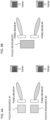
- the SRSs using the plurality of TRPs are at least one of SRSs in repetition of a physical uplink shared channel (PUSCH) using the unified TCI state and SRSs in PUSCHs transmitted in a same time domain by using a plurality of panels.
- PUSCH physical uplink shared channel
- radio communication system a structure of a radio communication system according to one embodiment of the present disclosure will be described.
- the radio communication method according to each embodiment of the present disclosure described above may be used alone or may be used in combination for communication.
- the radio communication system 1 may support dual connectivity (multi-RAT dual connectivity (MR-DC)) between a plurality of Radio Access Technologies (RATs).
- the MR-DC may include dual connectivity (E-UTRA-NR Dual Connectivity (EN-DC)) between LTE (Evolved Universal Terrestrial Radio Access (E-UTRA)) and NR, dual connectivity (NR-E-UTRA Dual Connectivity (NE-DC)) between NR and LTE, and so on.
- a base station (eNB) of LTE (E-UTRA) is a master node (MN), and a base station (gNB) of NR is a secondary node (SN).
- a base station (gNB) of NR is an MN
- a base station (eNB) of LTE (E-UTRA) is an SN.
- the radio communication system 1 may support dual connectivity between a plurality of base stations in the same RAT (for example, dual connectivity (NR-NR Dual Connectivity (NN-DC)) where both of an MN and an SN are base stations (gNB) of NR).
- dual connectivity NR-NR Dual Connectivity (NN-DC)
- gNB base stations
- the radio communication system 1 may include a base station 11 that forms a macro cell C1 of a relatively wide coverage, and base stations 12 (12a to 12c) that form small cells C2, which are placed within the macro cell C1 and which are narrower than the macro cell C1.
- the user terminal 20 may be located in at least one cell.
- the arrangement, the number, and the like of each cell and user terminal 20 are by no means limited to the aspect shown in the diagram.
- the base stations 11 and 12 will be collectively referred to as "base stations 10," unless specified otherwise.
- the user terminal 20 may be connected to at least one of the plurality of base stations 10.
- the user terminal 20 may use at least one of carrier aggregation (CA) and dual connectivity (DC) using a plurality of component carriers (CCs).
- CA carrier aggregation
- DC dual connectivity
- CCs component carriers
- Each CC may be included in at least one of a first frequency band (Frequency Range 1 (FR1)) and a second frequency band (Frequency Range 2 (FR2)).
- the macro cell C1 may be included in FR1
- the small cells C2 may be included in FR2.
- FR1 may be a frequency band of 6 GHz or less (sub-6 GHz)
- FR2 may be a frequency band which is higher than 24 GHz (above-24 GHz). Note that frequency bands, definitions and so on of FR1 and FR2 are by no means limited to these, and for example, FR1 may correspond to a frequency band which is higher than FR2.
- the user terminal 20 may communicate using at least one of time division duplex (TDD) and frequency division duplex (FDD) in each CC.
- TDD time division duplex
- FDD frequency division duplex
- the plurality of base stations 10 may be connected by a wired connection (for example, optical fiber in compliance with the Common Public Radio Interface (CPRI), the X2 interface and so on) or a wireless connection (for example, an NR communication).
- a wired connection for example, optical fiber in compliance with the Common Public Radio Interface (CPRI), the X2 interface and so on
- a wireless connection for example, an NR communication
- IAB Integrated Access Backhaul
- relay station relay station
- the base station 10 may be connected to a core network 30 through another base station 10 or directly.
- the core network 30 may include at least one of Evolved Packet Core (EPC), 5G Core Network (5GCN), Next Generation Core (NGC), and so on.
- EPC Evolved Packet Core
- 5GCN 5G Core Network
- NGC Next Generation Core
- the core network 30 may include network functions (NFs) such as User Plane Function (UPF), Access and Mobility management Function (AMF), Session Management Function (SMF), Unified Data Management (UDM), Application Function (AF), Data Network (DN), Location Management Function (LMF), and operation, administration and maintenance (Management) (OAM), for example.
- NFs network functions
- UPF User Plane Function
- AMF Access and Mobility management Function
- SMF Session Management Function
- UDM Unified Data Management
- AF Application Function
- DN Data Network
- LMF Location Management Function
- OAM operation, administration and maintenance
- a plurality of functions may be provided by one network node. Communication with an external network (for example, the Internet) may be performed via the DN.
- the user terminal 20 may be a terminal supporting at least one of communication schemes such as LTE, LTE-A, 5G, and so on.
- Uplink control information including at least one of channel state information (CSI), transmission confirmation information (for example, which may be referred to as Hybrid Automatic Repeat reQuest ACKnowledgement (HARQ-ACK), ACK/NACK, and so on), and scheduling request (SR) may be communicated by means of the PUCCH.
- CSI channel state information
- HARQ-ACK Hybrid Automatic Repeat reQuest ACKnowledgement
- ACK/NACK ACK/NACK
- SR scheduling request
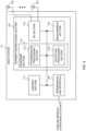
- the control section 110 controls the whole of the base station 10.
- the control section 110 can be constituted with a controller, a control circuit, or the like described based on general understanding of the technical field to which the present disclosure pertains.
- the transmitting/receiving section 120 may include a baseband section 121, a Radio Frequency (RF) section 122, and a measurement section 123.
- the baseband section 121 may include a transmission processing section 1211 and a reception processing section 1212.
- the transmitting/receiving section 120 can be constituted with a transmitter/receiver, an RF circuit, a baseband circuit, a filter, a phase shifter, a measurement circuit, a transmitting/receiving circuit, or the like described based on general understanding of the technical field to which the present disclosure pertains.
- the transmitting/receiving section 120 may be structured as a transmitting/receiving section in one entity, or may be constituted with a transmitting section and a receiving section.
- the transmitting section may be constituted with the transmission processing section 1211, and the RF section 122.
- the receiving section may be constituted with the reception processing section 1212, the RF section 122, and the measurement section 123.
- the transmitting/receiving antennas 130 can be constituted with antennas, for example, an array antenna, or the like described based on general understanding of the technical field to which the present disclosure pertains.
- the transmitting/receiving section 120 may transmit the above-described downlink channel, synchronization signal, downlink reference signal, and so on.
- the transmitting/receiving section 120 may receive the above-described uplink channel, uplink reference signal, and so on.
- the transmitting/receiving section 120 may form at least one of a transmit beam and a receive beam by using digital beam forming (for example, precoding), analog beam forming (for example, phase rotation), and so on.
- digital beam forming for example, precoding
- analog beam forming for example, phase rotation
- the transmitting/receiving section 120 may perform the processing of the Packet Data Convergence Protocol (PDCP) layer, the processing of the Radio Link Control (RLC) layer (for example, RLC retransmission control), the processing of the Medium Access Control (MAC) layer (for example, HARQ retransmission control), and so on, for example, on data and control information and so on acquired from the control section 110, and may generate bit string to transmit.
- PDCP Packet Data Convergence Protocol
- RLC Radio Link Control
- MAC Medium Access Control
- the transmitting/receiving section 120 may perform transmission processing such as channel coding (which may include error correction coding), modulation, mapping, filtering, discrete Fourier transform (DFT) processing (as necessary), inverse fast Fourier transform (IFFT) processing, precoding, digital-to-analog conversion, and so on, on the bit string to transmit, and output a baseband signal.
- transmission processing such as channel coding (which may include error correction coding), modulation, mapping, filtering, discrete Fourier transform (DFT) processing (as necessary), inverse fast Fourier transform (IFFT) processing, precoding, digital-to-analog conversion, and so on, on the bit string to transmit, and output a baseband signal.
- the transmitting/receiving section 120 may perform amplification, filtering, demodulation to a baseband signal, and so on, on the signal of the radio frequency band received by the transmitting/receiving antennas 130.
- the transmitting/receiving section 120 may apply reception processing such as analog-digital conversion, fast Fourier transform (FFT) processing, inverse discrete Fourier transform (IDFT) processing (as necessary), filtering, de-mapping, demodulation, decoding (which may include error correction decoding), MAC layer processing, the processing of the RLC layer and the processing of the PDCP layer, and so on, on the acquired baseband signal, and acquire user data, and so on.
- reception processing such as analog-digital conversion, fast Fourier transform (FFT) processing, inverse discrete Fourier transform (IDFT) processing (as necessary), filtering, de-mapping, demodulation, decoding (which may include error correction decoding), MAC layer processing, the processing of the RLC layer and the processing of the PDCP layer, and so on, on the acquired baseband signal, and acquire user data, and so on.
- FFT fast Fourier transform
- IDFT inverse discrete Fourier transform
- filtering de-mapping
- demodulation which
- the communication path interface 140 may perform transmission and reception (backhaul signaling) of signals with an apparatus included in the core network 30 (for example, a network node providing an NF), or another base station 10, and so on, and acquire or transmit user data (user plane data), control plane data, and so on for the user terminal 20.
- an apparatus included in the core network 30 for example, a network node providing an NF, or another base station 10, and so on, and acquire or transmit user data (user plane data), control plane data, and so on for the user terminal 20.
- the transmitting section and the receiving section of the base station 10 in the present disclosure may be constituted with at least one of the transmitting/receiving section 120, the transmitting/receiving antennas 130, and the communication path interface 140.
- the transmitting/receiving section 120 may transmit first information and second information for transmission power control of a plurality of physical uplink shared channels (PUSCHs) using a plurality of transmission/reception points (TRPs).
- the control section 110 may indicate a transmission power of a PUSCH corresponding to a first TRP of the plurality of TRPs by using the first information, and indicate a transmission power of a PUSCH corresponding to a second TRP of the plurality of TRPs by using the second information, when a unified Transmission Configuration Indication (TCI) state is not indicated.
- TCI Transmission Configuration Indication
- the transmitting/receiving section 120 may transmit first information and second information for transmission power control of a plurality of physical uplink control channels (PUCCHs) using a plurality of transmission/reception points (TRPs).
- the control section 110 may indicate a transmission power of a PUCCH corresponding to a first TRP of the plurality of TRPs by using the first information, and indicate a transmission power of a PUCCH corresponding to a second TRP of the plurality of TRPs by using the second information, when a unified Transmission Configuration Indication (TCI) state is not indicated.
- TCI Transmission Configuration Indication
- the transmitting/receiving section 120 may transmit first information and second information for transmission power control of a plurality of sounding reference signals (SRSs) using a plurality of transmission/reception points (TRPs).
- the control section 110 may indicate transmission power of an SRS corresponding to a first TRP of the plurality of TRPs by using the first information, and indicate transmission power of an SRS corresponding to a second TRP of the plurality of TRPs by using the second information, when a unified Transmission Configuration Indication (TCI) state is not indicated.
- TCI Transmission Configuration Indication
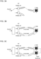
- FIG. 10 is a diagram to show an example of a structure of the user terminal according to one embodiment.
- the user terminal 20 includes a control section 210, a transmitting/receiving section 220, and transmitting/receiving antennas 230. Note that the user terminal 20 may include one or more control sections 210, one or more transmitting/receiving sections 220, and one or more transmitting/receiving antennas 230.
- the present example primarily shows functional blocks that pertain to characteristic parts of the present embodiment, and it is assumed that the user terminal 20 may include other functional blocks that are necessary for radio communication as well. Part of the processes of each section described below may be omitted.
- the control section 210 controls the whole of the user terminal 20.
- the control section 210 can be constituted with a controller, a control circuit, or the like described based on general understanding of the technical field to which the present disclosure pertains.
- the control section 210 may control generation of signals, mapping, and so on.
- the control section 210 may control transmission/reception, measurement and so on using the transmitting/receiving section 220, and the transmitting/receiving antennas 230.
- the control section 210 generates data, control information, a sequence and so on to transmit as a signal, and may forward the generated items to the transmitting/receiving section 220.
- the transmitting/receiving section 220 may include a baseband section 221, an RF section 222, and a measurement section 223.
- the baseband section 221 may include a transmission processing section 2211 and a reception processing section 2212.
- the transmitting/receiving section 220 can be constituted with a transmitter/receiver, an RF circuit, a baseband circuit, a filter, a phase shifter, a measurement circuit, a transmitting/receiving circuit, or the like described based on general understanding of the technical field to which the present disclosure pertains.
- the transmitting/receiving section 220 may be structured as a transmitting/receiving section in one entity, or may be constituted with a transmitting section and a receiving section.
- the transmitting section may be constituted with the transmission processing section 2211, and the RF section 222.
- the receiving section may be constituted with the reception processing section 2212, the RF section 222, and the measurement section 223.
- the transmitting/receiving antennas 230 can be constituted with antennas, for example, an array antenna, or the like described based on general understanding of the technical field to which the present disclosure pertains.
- the transmitting/receiving section 220 may receive the above-described downlink channel, synchronization signal, downlink reference signal, and so on.
- the transmitting/receiving section 220 may transmit the above-described uplink channel, uplink reference signal, and so on.
- the transmitting/receiving section 220 may form at least one of a transmit beam and a receive beam by using digital beam forming (for example, precoding), analog beam forming (for example, phase rotation), and so on.
- digital beam forming for example, precoding
- analog beam forming for example, phase rotation
- the transmitting/receiving section 220 may perform the processing of the PDCP layer, the processing of the RLC layer (for example, RLC retransmission control), the processing of the MAC layer (for example, HARQ retransmission control), and so on, for example, on data and control information and so on acquired from the control section 210, and may generate bit string to transmit.
- the transmitting/receiving section 220 may perform transmission processing such as channel coding (which may include error correction coding), modulation, mapping, filtering, DFT processing (as necessary), IFFT processing, precoding, digital-to-analog conversion, and so on, on the bit string to transmit, and output a baseband signal.
- transmission processing such as channel coding (which may include error correction coding), modulation, mapping, filtering, DFT processing (as necessary), IFFT processing, precoding, digital-to-analog conversion, and so on, on the bit string to transmit, and output a baseband signal.
- the transmitting/receiving section 220 may perform, for a given channel (for example, PUSCH), the DFT processing as the above-described transmission processing to transmit the channel by using a DFT-s-OFDM waveform if transform precoding is enabled, and otherwise, does not need to perform the DFT processing as the above-described transmission processing.
- a given channel for example, PUSCH
- the transmitting/receiving section 220 may perform modulation to a radio frequency band, filtering, amplification, and so on, on the baseband signal, and transmit the signal of the radio frequency band through the transmitting/receiving antennas 230.
- the transmitting/receiving section 220 may perform amplification, filtering, demodulation to a baseband signal, and so on, on the signal of the radio frequency band received by the transmitting/receiving antennas 230.
- the transmitting/receiving section 220 may apply reception processing such as analog-digital conversion, FFT processing, IDFT processing (as necessary), filtering, de-mapping, demodulation, decoding (which may include error correction decoding), MAC layer processing, the processing of the RLC layer and the processing of the PDCP layer, and so on, on the acquired baseband signal, and acquire user data, and so on.
- reception processing such as analog-digital conversion, FFT processing, IDFT processing (as necessary), filtering, de-mapping, demodulation, decoding (which may include error correction decoding), MAC layer processing, the processing of the RLC layer and the processing of the PDCP layer, and so on, on the acquired baseband signal, and acquire user data, and so on.
- the transmitting/receiving section 220 may perform the measurement related to the received signal.
- the measurement section 223 may perform RRM measurement, CSI measurement, and so on, based on the received signal.
- the measurement section 223 may measure a received power (for example, RSRP), a received quality (for example, RSRQ, SINR, SNR), a signal strength (for example, RSSI), channel information (for example, CSI), and so on.
- the measurement results may be output to the control section 210.
- the transmitting section and the receiving section of the user terminal 20 in the present disclosure may be constituted with at least one of the transmitting/receiving section 220 and the transmitting/receiving antennas 230.
- RRC signaling may be referred to as an "RRC message”, and can be, for example, an RRC connection setup message, an RRC connection reconfiguration message, and so on.
- MAC signaling may be notified using, for example, MAC control elements (MAC CEs).
- Software irrespective of whether referred to as “software”, “firmware”, “middleware”, “microcode”, or “hardware description language”, or called by other terms, should be interpreted broadly to mean instructions, instruction sets, codes, code segments, program codes, programs, subprograms, software modules, applications, software applications, software packages, routines, subroutines, objects, executable files, execution threads, procedures, functions, and the like.
- the base station may be referred to as the terms such as a “macro cell”, a “small cell”, a “femto cell”, a “pico cell”, and so on.
- transmitting information to the terminal by the base station may be interchangeably interpreted as instructing the terminal to perform control/operation based on the information by the base station.
- MS mobile station
- UE user equipment
- terminal terminal
- a mobile station may be referred to as a "subscriber station”, “mobile unit”, “subscriber unit”, “wireless unit”, “remote unit”, “mobile device”, “wireless device”, “wireless communication device”, “remote device”, “mobile subscriber station”, “access terminal”, “mobile terminal”, “wireless terminal”, “remote terminal”, “handset”, “user agent”, “mobile client”, “client”, or some other appropriate terms in some cases.
- At least one of a base station and a mobile station may be referred to as a "transmitting apparatus", a “receiving apparatus", a “radio communication apparatus” or the like.
- a base station and a mobile station may be a device mounted on a moving object or a moving object itself, and so on.
- the moving object is a movable object with any moving speed, and naturally, it also includes a moving object stopped.
- the moving object include a vehicle, a transport vehicle, an automobile, a motorcycle, a bicycle, a connected car, a loading shovel, a bulldozer, a wheel loader, a dump truck, a fork lift, a train, a bus, a trolley, a rickshaw, a ship and other watercraft, an airplane, a rocket, a satellite, a drone, a multicopter, a quadcopter, a balloon, and an object mounted on any of these, but these are not restrictive.
- the moving object may be a moving object that autonomously travels based on a direction for moving.
- the moving object may be a vehicle (for example, a car, an airplane, and the like), may be a moving object which moves unmanned (for example, a drone, an automatic operation car, and the like), or may be a robot (a manned type or unmanned type).
- a base station and a mobile station also includes an apparatus which does not necessarily move during communication operation.
- at least one of a base station and a mobile station may be an Internet of Things (IoT) device such as a sensor.
- IoT Internet of Things
- FIG. 12 is a diagram to show an example of a vehicle according to one embodiment.
- a vehicle 40 includes a driving section 41, a steering section 42, an accelerator pedal 43, a brake pedal 44, a shift lever 45, right and left front wheels 46, right and left rear wheels 47, an axle 48, an electronic control section 49, various sensors (including a current sensor 50, a rotational speed sensor 51, a pneumatic sensor 52, a vehicle speed sensor 53, an acceleration sensor 54, an accelerator pedal sensor 55, a brake pedal sensor 56, a shift lever sensor 57, and an object detection sensor 58), an information service section 59, and a communication module 60.
- various sensors including a current sensor 50, a rotational speed sensor 51, a pneumatic sensor 52, a vehicle speed sensor 53, an acceleration sensor 54, an accelerator pedal sensor 55, a brake pedal sensor 56, a shift lever sensor 57, and an object detection sensor 58
- an information service section 59 including a communication module 60.
- the driving section 41 includes, for example, at least one of an engine, a motor, and a hybrid of an engine and a motor.
- the steering section 42 includes at least a steering wheel (also referred to as a handle), and is configured to steer at least one of the front wheels 46 and the rear wheels 47, based on operation of the steering wheel operated by a user.
- the electronic control section 49 includes a microprocessor 61, a memory (ROM, RAM) 62, and a communication port (for example, an input/output (IO) port) 63.
- the electronic control section 49 receives, as input, signals from the various sensors 50 to 58 provided in the vehicle.
- the electronic control section 49 may be referred to as an Electronic Control Unit (ECU).
- ECU Electronic Control Unit
- Examples of the signals from the various sensors 50 to 58 include a current signal from the current sensor 50 for sensing current of a motor, a rotational speed signal of the front wheels 46/rear wheels 47 acquired by the rotational speed sensor 51, a pneumatic signal of the front wheels 46/rear wheels 47 acquired by the pneumatic sensor 52, a vehicle speed signal acquired by the vehicle speed sensor 53, an acceleration signal acquired by the acceleration sensor 54, a depressing amount signal of the accelerator pedal 43 acquired by the accelerator pedal sensor 55, a depressing amount signal of the brake pedal 44 acquired by the brake pedal sensor 56, an operation signal of the shift lever 45 acquired by the shift lever sensor 57, and a detection signal for detecting an obstruction, a vehicle, a pedestrian, and the like acquired by the object detection sensor 58.
- the information service section 59 includes: various devices for providing (outputting) various pieces of information such as driving information, traffic information, and entertainment information, such as a car navigation system, an audio system, a speaker, a display, a television, and a radio; and one or more ECUs that control these devices.
- the information service section 59 provides various pieces of information/services (for example, multimedia information/multimedia service) to an occupant of the vehicle 40, using information acquired from an external apparatus via the communication module 60 and the like.
- the information service section 59 may include an input device (for example, a keyboard, a mouse, a microphone, a switch, a button, a sensor, a touch panel, and the like) for receiving input from the outside, or may include an output device (for example, a display, a speaker, an LED lamp, a touch panel, and the like) for implementing output to the outside.
- an input device for example, a keyboard, a mouse, a microphone, a switch, a button, a sensor, a touch panel, and the like
- an output device for example, a display, a speaker, an LED lamp, a touch panel, and the like
- a driving assistance system section 64 includes: various devices for providing functions for preventing an accident and reducing a driver's driving load, such as a millimeter wave radar, Light Detection and Ranging (LiDAR), a camera, a positioning locator (for example, a Global Navigation Satellite System (GNSS) and the like), map information (for example, a high definition (HD) map, an autonomous vehicle (AV) map, and the like), a gyro system (for example, an inertial measurement apparatus (inertial measurement unit (IMU)), an inertial navigation apparatus (inertial navigation system (INS)), and the like), an artificial intelligence (AI) chip, and an AI processor; and one or more ECUs that control these devices.
- the driving assistance system section 64 transmits and receives various pieces of information via the communication module 60, and implements a driving assistance function or an autonomous driving function.
- the communication module 60 can communicate with the microprocessor 61 and the constituent elements of the vehicle 40 via the communication port 63.
- the communication module 60 transmits and receives data (information), via the communication port 63, to and from the driving section 41, the steering section 42, the accelerator pedal 43, the brake pedal 44, the shift lever 45, the right and left front wheels 46, the right and left rear wheels 47, the axle 48, the microprocessor 61 and the memory (ROM, RAM) 62 in the electronic control section 49, and the various sensors 50 to 58, which are included in the vehicle 40.
- the communication module 60 is a communication device that can be controlled by the microprocessor 61 of the electronic control section 49 and that can perform communication with an external apparatus. For example, the communication module 60 performs transmission and reception of various pieces of information to and from the external apparatus via radio communication.
- the communication module 60 may be either inside or outside the electronic control section 49.
- the external apparatus may be, for example, the base station 10, the user terminal 20, or the like described above.
- the communication module 60 may be, for example, at least one of the base station 10 and the user terminal 20 described above (may function as at least one of the base station 10 and the user terminal 20).
- the communication module 60 may transmit at least one of signals input from the various sensors 50 to 58 to the electronic control section 49, information obtained based on the signals, and information based on an input from the outside (a user) obtained via the information service section 59, to the external apparatus via radio communication.
- the electronic control section 49, the various sensors 50 to 58, the information service section 59, and the like may be referred to as input sections that receive input.
- the PUSCH transmitted by the communication module 60 may include information based on the input.
- the communication module 60 receives various pieces of information (traffic information, signal information, inter-vehicle distance information, and the like) transmitted from the external apparatus, and displays the received information on the information service section 59 included in the vehicle.
- the information service section 59 may be referred to as an output section that outputs information (for example, outputs information to devices, such as a display and a speaker, based on the PDSCH received by the communication module 60 (or data/information decoded from the PDSCH)).
- the communication module 60 stores the various pieces of information received from the external apparatus in the memory 62 that can be used by the microprocessor 61. Based on the pieces of information stored in the memory 62, the microprocessor 61 may control the driving section 41, the steering section 42, the accelerator pedal 43, the brake pedal 44, the shift lever 45, the right and left front wheels 46, the right and left rear wheels 47, the axle 48, the various sensors 50 to 58, and the like provided in the vehicle 40.
- the base station in the present disclosure may be interpreted as a user terminal.
- each aspect/embodiment of the present disclosure may be applied to the structure that replaces a communication between a base station and a user terminal with a communication between a plurality of user terminals (for example, which may be referred to as "Device-to-Device (D2D)", “Vehicle-to-Everything (V2X)", and the like).
- user terminals 20 may have the functions of the base stations 10 described above.
- the words such as "uplink” and “downlink” may be interpreted as the words corresponding to the terminal-to-terminal communication (for example, "sidelink”).
- an uplink channel, a downlink channel and so on may be interpreted as a sidelink channel.
- the user terminal in the present disclosure may be interpreted as a base station.
- the base station 10 may have the functions of the user terminal 20 described above.
- Operations which have been described in the present disclosure to be performed by a base station may, in some cases, be performed by an upper node of the base station.
- a network including one or a plurality of network nodes with base stations it is clear that various operations that are performed to communicate with terminals can be performed by base stations, one or more network nodes (for example, Mobility Management Entities (MMEs), Serving-Gateways (S-GWs), and so on may be possible, but these are not limiting) other than base stations, or combinations of these.
- MMEs Mobility Management Entities
- S-GWs Serving-Gateways
- Each aspect/embodiment described in the present disclosure may be used independently, may be used in combination, or may be switched depending on the mode of implementation.
- the order of processes, sequences, flowcharts, and so on that have been used to describe the aspects/embodiments in the present disclosure may be re-ordered as long as inconsistencies do not arise.
- various methods have been illustrated in the present disclosure with various components of steps in exemplary orders, the specific orders that are illustrated herein are by no means limiting.
- LTE Long Term Evolution
- LTE-A LTE-Advanced
- LTE-B LTE-Beyond
- SUPER 3G IMT-Advanced
- 4th generation mobile communication system 4th generation mobile communication system
- 5G 5th generation mobile communication system
- 6G 6th generation mobile communication system
- xG xth generation mobile communication system (where x is, for example, an integer or a decimal)
- Future Radio Access FAA
- RAT New-Radio Access Technology
- NR New Radio
- NX New radio access
- FX Future generation radio access
- GSM registered trademark
- CDMA 2000 Ultra Mobile Broadband
- UMB Ultra Mobile Broadband
- IEEE 802.11 Wi-Fi (registered trademark)
- IEEE 802.16 WiMAX (registered trademark)
- IEEE 802.20 Ultra-WideBand (UWB), Bluetooth (registered trademark), systems that use other adequate radio communication methods and next-generation systems that are enhanced, modified, created, or
- phrase “based on” (or “on the basis of”) as used in the present disclosure does not mean “based only on” (or “only on the basis of”), unless otherwise specified.
- the phrase “based on” (or “on the basis of”) means both “based only on” and “based at least on” (“only on the basis of” and “at least on the basis of”).
- references to elements with designations such as “first”, “second”, and so on as used in the present disclosure does not generally limit the quantity or order of these elements. These designations may be used in the present disclosure only for convenience, as a method for distinguishing between two or more elements. Thus, reference to the first and second elements does not imply that only two elements may be employed, or that the first element must precede the second element in some way.
- deciding (determining) may encompass a wide variety of actions. For example, “deciding (determining)” may be interpreted to mean making “decisions(determinations)” about judging, calculating, computing, processing, deriving, investigating, looking up, search and inquiry (for example, searching a table, a database, or some other data structures), ascertaining, and so on.
- deciding (determining) may be interpreted to mean making “decisions(determinations)” about receiving (for example, receiving information), transmitting (for example, transmitting information), input, output, accessing (for example, accessing data in a memory), and so on.
- deciding (determining) as used herein may be interpreted to mean making “decisions(determinations)” about resolving, selecting, choosing, establishing, comparing, and so on. In other words, “deciding (determining)” may be interpreted to mean making “decisions (determinations)” about some action.
- the maximum transmit power described in the present disclosure may mean a maximum value of the transmit power, may mean the nominal maximum transmit power (the nominal UE maximum transmit power), or may mean the rated maximum transmit power (the rated UE maximum transmit power).
- connection means any direct or indirect connections or coupling between two or more elements, and may include the presence of one or more intermediate elements between two elements that are “connected” or “coupled” to each other.
- the coupling or connection between the elements may be physical, logical, or a combination thereof. For example, “connection” may be interpreted as "access”.
- the two elements when two elements are connected, the two elements may be considered “connected” or “coupled” to each other by using one or more electrical wires, cables and printed electrical connections, and, as some non-limiting and non-inclusive examples, by using electromagnetic energy having wavelengths in radio frequency regions, microwave regions, (both visible and invisible) optical regions, or the like.
- phrase "A and B are different” may mean that "A and B are different from each other”. It should be noted that the phrase may mean that "A and B are each different from C”.
- the terms "separate”, “coupled”, and so on may be interpreted similarly to "different”.
- the present disclosure may include that a noun after the article is in a plural form.
- expressions obtained by adding "i-th” (i is any integer) to words such as “good”, “bad”, “large”, “small”, “high”, “low”, “early”, “late”, “wide”, “narrow”, and the like may be used interchangeably irrespective of positive degree, comparative degree, and superlative degree (for example, “best” may be used interchangeably with “i-th best", and vice versa).
Landscapes
- Engineering & Computer Science (AREA)
- Computer Networks & Wireless Communication (AREA)
- Signal Processing (AREA)
- Quality & Reliability (AREA)
- Physics & Mathematics (AREA)
- Electromagnetism (AREA)
- Mobile Radio Communication Systems (AREA)
Applications Claiming Priority (2)
| Application Number | Priority Date | Filing Date | Title |
|---|---|---|---|
| JP2022132835 | 2022-08-23 | ||
| PCT/JP2023/026409 WO2024042926A1 (ja) | 2022-08-23 | 2023-07-19 | 端末、無線通信方法及び基地局 |
Publications (1)
| Publication Number | Publication Date |
|---|---|
| EP4580266A1 true EP4580266A1 (de) | 2025-07-02 |
Family
ID=90013266
Family Applications (1)
| Application Number | Title | Priority Date | Filing Date |
|---|---|---|---|
| EP23857042.8A Pending EP4580266A1 (de) | 2022-08-23 | 2023-07-19 | Endgerät, drahtloskommunikationsverfahren und basisstation |
Country Status (2)
| Country | Link |
|---|---|
| EP (1) | EP4580266A1 (de) |
| WO (1) | WO2024042926A1 (de) |
Family Cites Families (1)
| Publication number | Priority date | Publication date | Assignee | Title |
|---|---|---|---|---|
| JP7581964B2 (ja) | 2021-03-01 | 2024-11-13 | スズキ株式会社 | シフト装置 |
-
2023
- 2023-07-19 EP EP23857042.8A patent/EP4580266A1/de active Pending
- 2023-07-19 WO PCT/JP2023/026409 patent/WO2024042926A1/ja not_active Ceased
Also Published As
| Publication number | Publication date |
|---|---|
| WO2024042926A1 (ja) | 2024-02-29 |
| JPWO2024042926A1 (de) | 2024-02-29 |
Similar Documents
| Publication | Publication Date | Title |
|---|---|---|
| EP4496405A1 (de) | Endgerät, funkkommunikationsverfahren und basisstation | |
| US20240407037A1 (en) | Terminal, radio communication method, and base station | |
| EP4422245A1 (de) | Endgerät, drahtloskommunikationsverfahren und basisstation | |
| US20250279869A1 (en) | Terminal, radio communication method, and base station | |
| EP4568125A1 (de) | Endgerät, drahtloskommunikationsverfahren und basisstation | |
| US20240414734A1 (en) | Terminal, radio communication method, and base station | |
| EP4615074A1 (de) | Endgerät, drahtloskommunikationsverfahren und basisstation | |
| EP4486035A1 (de) | Endgerät, funkkommunikationsverfahren und basisstation | |
| EP4568126A1 (de) | Endgerät, drahtloskommunikationsverfahren und basisstation | |
| EP4572366A1 (de) | Endgerät, drahtloskommunikationsverfahren und basisstation | |
| EP4554268A1 (de) | Endgerät, drahtloskommunikationsverfahren und basisstation | |
| EP4615058A1 (de) | Endgerät, drahtloskommunikationsverfahren und basisstation | |
| EP4412346A1 (de) | Endgerät, funkkommunikationsverfahren und basisstation | |
| EP4580266A1 (de) | Endgerät, drahtloskommunikationsverfahren und basisstation | |
| EP4597863A1 (de) | Endgerät, drahtloskommunikationsverfahren und basisstation | |
| EP4572170A1 (de) | Endgerät, drahtloskommunikationsverfahren und basisstation | |
| EP4694272A1 (de) | Endgerät, drahtloskommunikationsverfahren und basisstation | |
| EP4598151A1 (de) | Endgerät, drahtloskommunikationsverfahren und basisstation | |
| EP4622375A1 (de) | Endgerät, drahtloskommunikationsverfahren und basisstation | |
| EP4676146A1 (de) | Endgerät, drahtloskommunikationsverfahren und basisstation | |
| EP4723499A1 (de) | Endgerät, drahtloskommunikationsverfahren und basisstation | |
| EP4618433A1 (de) | Endgerät, drahtloskommunikationsverfahren und basisstation | |
| EP4683400A1 (de) | Endgerät, drahtloskommunikationsverfahren und basisstation | |
| US20260100788A1 (en) | Terminal, radio communication method, and base station | |
| EP4686293A1 (de) | Endgerät, drahtloskommunikationsverfahren und basisstation |
Legal Events
| Date | Code | Title | Description |
|---|---|---|---|
| STAA | Information on the status of an ep patent application or granted ep patent |
Free format text: STATUS: THE INTERNATIONAL PUBLICATION HAS BEEN MADE |
|
| PUAI | Public reference made under article 153(3) epc to a published international application that has entered the european phase |
Free format text: ORIGINAL CODE: 0009012 |
|
| STAA | Information on the status of an ep patent application or granted ep patent |
Free format text: STATUS: REQUEST FOR EXAMINATION WAS MADE |
|
| 17P | Request for examination filed |
Effective date: 20250307 |
|
| AK | Designated contracting states |
Kind code of ref document: A1 Designated state(s): AL AT BE BG CH CY CZ DE DK EE ES FI FR GB GR HR HU IE IS IT LI LT LU LV MC ME MK MT NL NO PL PT RO RS SE SI SK SM TR |
|
| DAV | Request for validation of the european patent (deleted) | ||
| DAX | Request for extension of the european patent (deleted) |