EP4580256A2 - Verfahren zur liefermodusumschaltung für multicast- und broadcast-dienst in einem 5g-netzwerk - Google Patents
Verfahren zur liefermodusumschaltung für multicast- und broadcast-dienst in einem 5g-netzwerk Download PDFInfo
- Publication number
- EP4580256A2 EP4580256A2 EP25176376.9A EP25176376A EP4580256A2 EP 4580256 A2 EP4580256 A2 EP 4580256A2 EP 25176376 A EP25176376 A EP 25176376A EP 4580256 A2 EP4580256 A2 EP 4580256A2
- Authority
- EP
- European Patent Office
- Prior art keywords
- session
- multicast
- mbs
- information
- unicast
- Prior art date
- Legal status (The legal status is an assumption and is not a legal conclusion. Google has not performed a legal analysis and makes no representation as to the accuracy of the status listed.)
- Pending
Links
Images


Classifications
-
- H—ELECTRICITY
- H04—ELECTRIC COMMUNICATION TECHNIQUE
- H04W—WIRELESS COMMUNICATION NETWORKS
- H04W4/00—Services specially adapted for wireless communication networks; Facilities therefor
- H04W4/06—Selective distribution of broadcast services, e.g. multimedia broadcast multicast service [MBMS]; Services to user groups; One-way selective calling services
-
- H—ELECTRICITY
- H04—ELECTRIC COMMUNICATION TECHNIQUE
- H04W—WIRELESS COMMUNICATION NETWORKS
- H04W72/00—Local resource management
- H04W72/30—Resource management for broadcast services
-
- H—ELECTRICITY
- H04—ELECTRIC COMMUNICATION TECHNIQUE
- H04W—WIRELESS COMMUNICATION NETWORKS
- H04W76/00—Connection management
- H04W76/10—Connection setup
- H04W76/12—Setup of transport tunnels
-
- H—ELECTRICITY
- H04—ELECTRIC COMMUNICATION TECHNIQUE
- H04W—WIRELESS COMMUNICATION NETWORKS
- H04W76/00—Connection management
- H04W76/40—Connection management for selective distribution or broadcast
-
- H—ELECTRICITY
- H04—ELECTRIC COMMUNICATION TECHNIQUE
- H04W—WIRELESS COMMUNICATION NETWORKS
- H04W36/00—Hand-off or reselection arrangements
- H04W36/0005—Control or signalling for completing the hand-off
- H04W36/0007—Control or signalling for completing the hand-off for multicast or broadcast services, e.g. MBMS
-
- H—ELECTRICITY
- H04—ELECTRIC COMMUNICATION TECHNIQUE
- H04W—WIRELESS COMMUNICATION NETWORKS
- H04W36/00—Hand-off or reselection arrangements
- H04W36/34—Reselection control
- H04W36/36—Reselection control by user or terminal equipment
Definitions
- MooD is an application layer solution; thus, it presents the following inefficiencies.
- Control signaling is transferred at application layer to enable the switch. It may not be efficient to transfer the control information at the application layer since many different applications will use the multicast/broadcast service. This approach may require all applications to support the MooD protocol. This approach is also prone to a slow reaction time to adjusting both core network and radio resource usage strategy to the prevailing resource usage status in either the core network or the radio network.
- System and methods that provide switching between at least two unicast messaging, multicast messaging, and broadcast messaging to a user device over a 5G network.
- the procedure may be performed in the manner.
- a determining is made whether a triggering event has occurred at one or more of a user device (e.g., UE), a network device, content provider system, or RAN node.
- the triggering event indicates a need to switch between a first one and a second one of unicast messaging, multicast messaging, and broadcast message.
- a switch based upon the occurrence of the triggering event, from the first one of the unicast messaging, the multicast messaging, and the broadcast messaging to the second one of the unicast messaging, the multicast messaging, and the broadcast messaging to the user device is initiated.
- the 3rd Generation Partnership Project (3GPP) develops technical standards for cellular telecommunications network technologies, including radio access, the core transport network, and service capabilities - including work on codecs, security, and quality of service.
- Recent radio access technology (RAT) standards include WCDMA (commonly referred as 3G), LTE (commonly referred as 4G), and LTE-Advanced standards.
- 3GPP has begun working on the standardization of next generation cellular technology, called New Radio (NR), which is also referred to as "5G”.
- 3GPP NR standards development is expected to include the definition of next generation radio access technology (new RAT), which is expected to include the provision of new flexible radio access below 6 GHz, and the provision of new ultra-mobile broadband radio access above 6 GHz.
- new RAT next generation radio access technology
- 3GPP has identified a variety of use cases that NR is expected to support, resulting in a wide variety of user experience requirements for data rate, latency, and mobility.
- the use cases include the following general categories: enhanced mobile broadband (e.g., broadband access in dense areas, indoor ultra-high broadband access, broadband access in a crowd, 50+ Mbps everywhere, ultra-low cost broadband access, mobile broadband in vehicles), critical communications, massive machine type communications, network operation (e.g., network slicing, routing, migration and interworking, energy savings), and enhanced vehicle-to-everything (eV2X) communications, which may include any of Vehicle-to-Vehicle Communication (V2V), Vehicle-to-Infrastructure Communication (V2I), Vehicle-to-Network Communication (V2N), Vehicle-to-Pedestrian Communication (V2P), and vehicle communications with other entitites.
- V2V Vehicle-to-Vehicle Communication
- V2I Vehicle-to-Infrastructure Communication
- V2N Vehicle-
- Specific service and applications in these categories include, e.g., monitoring and sensor networks, device remote controlling, bi-directional remote controlling, personal cloud computing, video streaming, wireless cloud-based office, first responder connectivity, automotive ecall, disaster alerts, real-time gaming, multi-person video calls, autonomous driving, augmented reality, tactile internet, and virtual reality to name a few. All of these use cases and others are contemplated herein.
- Each of the WTRUs 102a, 102b, 102c, 102d, 102e, 102f, 102g may be any type of apparatus or device configured to operate and/or communicate in a wireless environment.
- each WTRU 102a, 102b, 102c, 102d, 102e, 102f, 102g is depicted in Figures 1A-1E as a hand-held wireless communications apparatus, it is understood that with the wide variety of use cases contemplated for 5G wireless communications, each WTRU may comprise or be embodied in any type of apparatus or device configured to transmit and/or receive wireless signals, including, by way of example only, user equipment (UE), a mobile station, a fixed or mobile subscriber unit, a pager, a cellular telephone, a personal digital assistant (PDA), a smartphone, a laptop, a tablet, a netbook, a notebook computer, a personal computer, a wireless sensor, consumer electronics, a wearable device such as a smart watch or smart clothing,
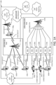
- Base stations 114b may be any type of device configured to wiredly and/or wirelessly interface with at least one of the RRHs (Remote Radio Heads) 118a, 118b, TRPs (Transmission and Reception Points) 119a, 119b, and/or RSUs (Roadside Units) 120a and 120b to facilitate access to one or more communication networks, such as the core network 106/107/109, the Internet 110, the other networks 112, and/or V2X server (or ProSe function and server) 113.
- RRHs Remote Radio Heads
- TRPs Transmission and Reception Points
- RSUs Raadside Units
- RSUs 120a and 120b may be any type of device configured to wirelessly interface with at least one of the WTRU 102e or 102f, to facilitate access to one or more communication networks, such as the core network 106/107/109, the Internet 110, the other networks 112, and/or V2X server (or ProSe function and server) 113.
- the base stations 114a, 114b may be a base transceiver station (BTS), a Node-B, an eNode B, a Home Node B, a Home eNode B, a site controller, an access point (AP), a wireless router, and the like. While the base stations 114a, 114b are each depicted as a single element, it will be appreciated that the base stations 114a, 114b may include any number of interconnected base stations and/or network elements.
- the base stations 114b may communicate with one or more of the RRHs 118a, 118b, TRPs 119a, 119b, and/or RSUs 120a and 120b, over a wired or air interface 115b/116b/117b, which may be any suitable wired (e.g., cable, optical fiber, etc.) or wireless communication link (e.g., radio frequency (RF), microwave, infrared (IR), ultraviolet (UV), visible light, cmWave, mmWave, etc.).
- the air interface 115b/116b/117b may be established using any suitable radio access technology (RAT).
- RAT radio access technology
- the WTRUs 102a, 102b, 102c,102d, 102e, 102f, and/or 102g may communicate with one another over an air interface 115d/116d/117d (not shown in the figures), which may be any suitable wireless communication link (e.g., radio frequency (RF), microwave, infrared (IR), ultraviolet (UV), visible light, cmWave, mmWave, etc.).
- the air interface 115d/116d/117d may be established using any suitable radio access technology (RAT).
- RAT radio access technology
- the communications system 100 may be a multiple access system and may employ one or more channel access schemes, such as CDMA, TDMA, FDMA, OFDMA, SC-FDMA, and the like.
- the base station 114a in the RAN 103/104/105 and the WTRUs 102a, 102b, 102c, or RRHs 118a, 118b,TRPs 119a, 119b and RSUs 120a, 120b, in the RAN 103b/104b/105b and the WTRUs 102c, 102d, 102e, 102f may implement a radio technology such as Universal Mobile Telecommunications System (UMTS) Terrestrial Radio Access (UTRA), which may establish the air interface 115/116/117 or 115c/116c/117c respectively using wideband CDMA (WCDMA).
- UMTS Universal Mobile Telecommunications System
- UTRA Universal Mobile Telecommunications System
- WCDMA wideband CDMA
- WCDMA may include communication protocols such as High-Speed Packet Access (HSPA) and/or Evolved HSPA (HSPA+).
- HSPA may include High-Speed Downlink Packet Access (HSDPA) and/or High-Speed Uplink Packet Access (HSUPA).
- HSPA High-Speed Packet Access
- HSDPA High-Speed Downlink Packet Access
- HSUPA High-Speed Uplink Packet Access
- the base station 114a and the WTRUs 102a, 102b, 102c, or RRHs 118a, 118b, TRPs 119a, 119b, and/or RSUs 120a, 120b, in the RAN 103b/104b/105b and the WTRUs 102c, 102d may implement a radio technology such as Evolved UMTS Terrestrial Radio Access (E-UTRA), which may establish the air interface 115/116/117 or 115c/116c/117c respectively using Long Term Evolution (LTE) and/or LTE-Advanced (LTE-A).
- LTE Long Term Evolution
- LTE-A LTE-Advanced
- the air interface 115/116/117 may implement 3GPP NR technology.
- the LTE and LTE-A technology includes LTE D2D and V2X technologies and interface (such as Sidelink communications and etc).
- the 3GPP NR technology includes NR V2X technologies and interface (such as Side
- the base station 114a in the RAN 103/104/105 and the WTRUs 102a, 102b, 102c, or RRHs 118a, 118b, TRPs 119a, 119b and/or RSUs 120a, 120b, in the RAN 103b/104b/105b and the WTRUs 102c, 102d, 102e, 102f may implement radio technologies such as IEEE 802.16 (e.g., Worldwide Interoperability for Microwave Access (WiMAX)), CDMA2000, CDMA2000 1X, CDMA2000 EV-DO, Interim Standard 2000 (IS-2000), Interim Standard 95 (IS-95), Interim Standard 856 (IS-856), Global System for Mobile communications (GSM), Enhanced Data rates for GSM Evolution (EDGE), GSM EDGE (GERAN), and the like.
- IEEE 802.16 e.g., Worldwide Interoperability for Microwave Access (WiMAX)
- the base station 114c in FIG. 1A may be a wireless router, Home Node B, Home eNode B, or access point, for example, and may utilize any suitable RAT for facilitating wireless connectivity in a localized area, such as a place of business, a home, a vehicle, a campus, and the like, for implementing the methods systems, and devices of delivery mode switch for multicast and broadcast service in a network, as disclosed herein.
- the base station 114c and the WTRUs 102e may implement a radio technology such as IEEE 802.11 to establish a wireless local area network (WLAN).
- WLAN wireless local area network
- the RAN 103/104/105 and/or RAN 103b/104b/105b may be in communication with the core network 106/107/109, which may be any type of network configured to provide voice, data, applications, and/or voice over internet protocol (VoIP) services to one or more of the WTRUs 102a, 102b, 102c, 102d.
- the core network 106/107/109 may provide call control, billing services, mobile location-based services, prepaid calling, Internet connectivity, video distribution, etc., and/or perform high-level security functions, such as user authentication.
- the core network 106/107/109 may also serve as a gateway for the WTRUs 102a, 102b, 102c, 102d, 102e to access the PSTN 108, the Internet 110, and/or other networks 112.
- the PSTN 108 may include circuit-switched telephone networks that provide plain old telephone service (POTS).
- POTS plain old telephone service
- the Internet 110 may include a global system of interconnected computer networks and devices that use common communication protocols, such as the transmission control protocol (TCP), user datagram protocol (UDP) and the internet protocol (IP) in the TCP/IP internet protocol suite.
- the networks 112 may include wired or wireless communications networks owned and/or operated by other service providers.
- the networks 112 may include another core network connected to one or more RANs, which may employ the same RAT as the RAN 103/104/105 and/or RAN 103b/104b/105b or a different RAT.
- the WTRUs 102a, 102b, 102c, 102d in the communications system 100 may include multi-mode capabilities, e.g., the WTRUs 102a, 102b, 102c, 102d, and 102e may include multiple transceivers for communicating with different wireless networks over different wireless links for implementing methods, systems, and devices of delivery mode switch for multicast and broadcast service in a network.
- the WTRU 102e shown in FIG. 1A may be configured to communicate with the base station 114a, which may employ a cellular-based radio technology, and with the base station 114c, which may employ an IEEE 802 radio technology.
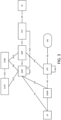
- FIG. 1B is a block diagram of an example apparatus or device configured for wireless communications in accordance with the embodiments illustrated herein, such as for example, a WTRU 102.
- the example WTRU 102 may include a processor 118, a transceiver 120, a transmit/receive element 122, a speaker/microphone 124, a keypad 126, a display/touchpad/indicators 128, non-removable memory 130, removable memory 132, a power source 134, a global positioning system (GPS) chipset 136, and other peripherals 138.
- GPS global positioning system
- the base stations 114a and 114b, and/or the nodes that base stations 114a and 114b may represent, such as but not limited to transceiver station (BTS), a Node-B, a site controller, an access point (AP), a home node-B, an evolved home node-B (eNodeB), a home evolved node-B (HeNB), a home evolved node-B gateway, and proxy nodes, among others, may include some or all of the elements depicted in FIG. 1B and described herein.
- BTS transceiver station
- Node-B a Node-B
- AP access point
- eNodeB evolved home node-B
- HeNB home evolved node-B gateway
- proxy nodes among others, may include some or all of the elements depicted in FIG. 1B and described herein.
- the processor 118 may be a general purpose processor, a special purpose processor, a conventional processor, a digital signal processor (DSP), a plurality of microprocessors, one or more microprocessors in association with a DSP core, a controller, a microcontroller, Application Specific Integrated Circuits (ASICs), Field Programmable Gate Array (FPGAs) circuits, any other type of integrated circuit (IC), a state machine, and the like.
- the processor 118 may perform signal coding, data processing, power control, input/output processing, and/or any other functionality that enables the WTRU 102 to operate in a wireless environment.
- the processor 118 may be coupled to the transceiver 120, which may be coupled to the transmit/receive element 122. While FIG. 1B depicts the processor 118 and the transceiver 120 as separate components, it will be appreciated that the processor 118 and the transceiver 120 may be integrated together in an electronic package or chip.
- the transmit/receive element 122 may be configured to transmit signals to, or receive signals from, a base station (e.g., the base station 114a) over the air interface 115/116/117.
- a base station e.g., the base station 114a
- the transmit/receive element 122 may be an antenna configured to transmit and/or receive RF signals.
- the transmit/receive element 122 may be an emitter/detector configured to transmit and/or receive IR, UV, or visible light signals, for example.
- the transmit/receive element 122 may be configured to transmit and receive both RF and light signals. It will be appreciated that the transmit/receive element 122 may be configured to transmit and/or receive any combination of wireless signals.
- the WTRU 102 may include any number of transmit/receive elements 122. More specifically, the WTRU 102 may employ MIMO technology. Thus, in an embodiment, the WTRU 102 may include two or more transmit/receive elements 122 (e.g., multiple antennas) for transmitting and receiving wireless signals over the air interface 115/116/117.
- the WTRU 102 may include two or more transmit/receive elements 122 (e.g., multiple antennas) for transmitting and receiving wireless signals over the air interface 115/116/117.
- the WTRU 102 may be embodied in other apparatuses or devices, such as a sensor, consumer electronics, a wearable device such as a smart watch or smart clothing, a medical or eHealth device, a robot, industrial equipment, a drone, a vehicle such as a car, truck, train, or airplane.
- the WTRU 102 may connect to other components, modules, or systems of such apparatuses or devices via one or more interconnect interfaces, such as an interconnect interface that may comprise one of the peripherals 138.
- FIG. 1C is a system diagram of the RAN 103 and the core network 106 according to an embodiment.
- the RAN 103 may employ a UTRA radio technology to communicate with the WTRUs 102a, 102b, and 102c over the air interface 115.
- the RAN 103 may also be in communication with the core network 106.
- the RAN 103 may include Node-Bs 140a, 140b, 140c, which may each include one or more transceivers for communicating with the WTRUs 102a, 102b, 102c over the air interface 115.
- the Node-Bs 140a, 140b, 140c may each be associated with a particular cell (not shown) within the RAN 103.
- the RAN 103 may also include RNCs 142a, 142b. It will be appreciated that the RAN 103 may include any number of Node-Bs and RNCs while remaining consistent with an embodiment.
- the Node-Bs 140a, 140b may be in communication with the RNC 142a. Additionally, the Node-B 140c may be in communication with the RNC 142b.
- the Node-Bs 140a, 140b, 140c may communicate with the respective RNCs 142a, 142b via an Iub interface.
- the RNCs 142a, 142b may be in communication with one another via an Iur interface.
- Each of the RNCs 142a, 142b may be configured to control the respective Node-Bs 140a, 140b, 140c to which it is connected.
- each of the RNCs 142a, 142b may be configured to carry out or support other functionality, such as outer loop power control, load control, admission control, packet scheduling, handover control, macro-diversity, security functions, data encryption, and the like.
- the core network 106 shown in FIG. 1C may include a media gateway (MGW) 144, a mobile switching center (MSC) 146, a serving GPRS support node (SGSN) 148, and/or a gateway GPRS support node (GGSN) 150. While each of the foregoing elements are depicted as part of the core network 106, it will be appreciated that any one of these elements may be owned and/or operated by an entity other than the core network operator.
- MGW media gateway
- MSC mobile switching center
- SGSN serving GPRS support node
- GGSN gateway GPRS support node
- the RNC 142a in the RAN 103 may be connected to the MSC 146 in the core network 106 via an IuCS interface.
- the MSC 146 may be connected to the MGW 144.
- the MSC 146 and the MGW 144 may provide the WTRUs 102a, 102b, 102c with access to circuit-switched networks, such as the PSTN 108, to facilitate communications between the WTRUs 102a, 102b, 102c and traditional land-line communications devices.
- the RNC 142a in the RAN 103 may also be connected to the SGSN 148 in the core network 106 via an IuPS interface.
- the SGSN 148 may be connected to the GGSN 150.
- the SGSN 148 and the GGSN 150 may provide the WTRUs 102a, 102b, 102c with access to packet-switched networks, such as the Internet 110, to facilitate communications between and the WTRUs 102a, 102b, 102c and IP-enabled devices.
- the core network 106 may also be connected to the networks 112, which may include other wired or wireless networks that are owned and/or operated by other service providers.
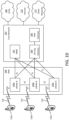
- FIG. 1D is a system diagram of the RAN 104 and the core network 107 that may implement methods, systems, and devices of delivery mode switch for multicast and broadcast service in a network, as disclosed herein.
- the RAN 104 may employ an E-UTRA radio technology to communicate with the WTRUs 102a, 102b, and 102c over the air interface 116.
- the RAN 104 may also be in communication with the core network 107.
- the RAN 104 may include eNode-Bs 160a, 160b, 160c, though it will be appreciated that the RAN 104 may include any number of eNode-Bs while remaining consistent with an embodiment.
- the eNode-Bs 160a, 160b, 160c may each include one or more transceivers for communicating with the WTRUs 102a, 102b, 102c over the air interface 116.
- the eNode-Bs 160a, 160b, 160c may implement MIMO technology.
- the eNode-B 160a for example, may use multiple antennas to transmit wireless signals to, and receive wireless signals from, the WTRU 102a.
- Each of the eNode-Bs 160a, 160b, and 160c may be associated with a particular cell (not shown) and may be configured to handle radio resource management decisions, handover decisions, scheduling of users in the uplink and/or downlink, and the like. As shown in FIG. 1D , the eNode-Bs 160a, 160b, 160c may communicate with one another over an X2 interface.
- the core network 107 shown in FIG. 1D may include a mobility management gateway (MME) 162, a serving gateway 164, and a packet data network (PDN) gateway 166. While each of the foregoing elements are depicted as part of the core network 107, it will be appreciated that any one of these elements may be owned and/or operated by an entity other than the core network operator.
- MME mobility management gateway
- PDN packet data network
- the MME 162 may be connected to each of the eNode-Bs 160a, 160b, and 160c in the RAN 104 via an S1 interface and may serve as a control node.
- the MME 162 may be responsible for authenticating users of the WTRUs 102a, 102b, 102c, bearer activation/deactivation, selecting a particular serving gateway during an initial attach of the WTRUs 102a, 102b, 102c, and the like.
- the MME 162 may also provide a control plane function for switching between the RAN 104 and other RANs (not shown) that employ other radio technologies, such as GSM or WCDMA.
- the serving gateway 164 may be connected to each of the eNode-Bs 160a, 160b, and 160c in the RAN 104 via the S1 interface.
- the serving gateway 164 may generally route and forward user data packets to/from the WTRUs 102a, 102b, 102c.
- the serving gateway 164 may also perform other functions, such as anchoring user planes during inter-eNode B handovers, triggering paging when downlink data is available for the WTRUs 102a, 102b, 102c, managing and storing contexts of the WTRUs 102a, 102b, 102c, and the like.
- the serving gateway 164 may also be connected to the PDN gateway 166, which may provide the WTRUs 102a, 102b, 102c with access to packet-switched networks, such as the Internet 110, to facilitate communications between the WTRUs 102a, 102b, 102c and IP-enabled devices.
- the PDN gateway 166 may provide the WTRUs 102a, 102b, 102c with access to packet-switched networks, such as the Internet 110, to facilitate communications between the WTRUs 102a, 102b, 102c and IP-enabled devices.
- the core network 107 may facilitate communications with other networks.
- the core network 107 may provide the WTRUs 102a, 102b, 102c with access to circuit-switched networks, such as the PSTN 108, to facilitate communications between the WTRUs 102a, 102b, 102c and traditional land-line communications devices.
- the core network 107 may include, or may communicate with, an IP gateway (e.g., an IP multimedia subsystem (IMS) server) that serves as an interface between the core network 107 and the PSTN 108.
- IMS IP multimedia subsystem
- the core network 107 may provide the WTRUs 102a, 102b, 102c with access to the networks 112, which may include other wired or wireless networks that are owned and/or operated by other service providers.
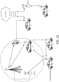
- FIG. 1E is a system diagram of the RAN 105 and the core network 109 according to the methods, systems, and devices of delivery mode switch for multicast and broadcast service in a network, as disclosed herein.
- the RAN 105 may be an access service network (ASN) that employs IEEE 802.16 radio technology to communicate with the WTRUs 102a, 102b, and 102c over the air interface 117.
- ASN access service network
- the communication links between the different functional entities of the WTRUs 102a, 102b, 102c, the RAN 105, and the core network 109 may be defined as reference points.
- the processor 91 may be a general purpose processor, a special purpose processor, a conventional processor, a digital signal processor (DSP), a plurality of microprocessors, one or more microprocessors in association with a DSP core, a controller, a microcontroller, Application Specific Integrated Circuits (ASICs), Field Programmable Gate Array (FPGAs) circuits, any other type of integrated circuit (IC), a state machine, and the like.
- the processor 91 may perform signal coding, data processing, power control, input/output processing, and/or any other functionality that enables the computing system 90 to operate in a communications network.
- Coprocessor 81 is an optional processor, distinct from main processor 91, that may perform additional functions or assist processor 91. Processor 91 and/or coprocessor 81 may receive, generate, and process data related to the methods and apparatuses disclosed herein.
- Display 86 which is controlled by display controller 96, is used to display visual output generated by computing system 90. Such visual output may include text, graphics, animated graphics, and video. The visual output may be provided in the form of a graphical user interface (GUI).
- GUI graphical user interface
- Display 86 may be implemented with a CRT-based video display, an LCD-based flat-panel display, gas plasma-based flat-panel display, or a touch-panel.
- Display controller 96 includes electronic components required to generate a video signal that is sent to display 86.
- WTRUs A, B, C form a V2X group, among which WTRU A is the group lead and WTRUs B and C are group members.
- WTRUs A, B, C, D, E, F may communicate over Uu interface or Sidelink (PC5) interface.
- any or all of the apparatuses, systems, methods and processes described herein may be embodied in the form of computer executable instructions (e.g., program code) stored on a computer-readable storage medium which instructions, when executed by a processor, such as processors 118 or 91, cause the processor to perform and/or implement the systems, methods and processes described herein.
- a processor such as processors 118 or 91
- any of the steps, operations or functions described herein may be implemented in the form of such computer executable instructions, executing on the processor of an apparatus or computing system configured for wireless and/or wired network communications.
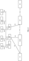
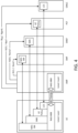
- FIG. 3 depicts the 5G System architecture in the non-roaming case, using the reference point representation showing how various network functions interact with each other.
- the end-to-end communications uses services provided by the 3GPP system, and optionally services provided by a Services Capability Server (SCS), which resides in the DN.
- SCS Services Capability Server
- FIG. 3 illustrates an exemplary NAS transport for SM, SMS, UE Policy, or LCS. It is worth noting that the mobility management and session management functions are separated.
- a single N1 NAS connection is used for both Registration Management and Connection Management (RM/CM) and for SM-related messages and procedures for a UE.
- the single N1 termination point is located in the AMF.
- the AMF forwards SM related NAS information to the SMF.
- AMF handles the Registration Management and Connection Management of NAS signaling exchanged with the UE, while SMF handles the Session management of NAS signaling exchanged with the UE.
- the architecture defines several types of control signaling that can be transferred on top of NAS-MM protocol, such as UE policy between PCF and UE, Location Service (LCS) between Gateway Mobile Location Centre (GMLC) and UE.
- UE policy between PCF and UE
- LCS Location Service
- GMLC Gateway Mobile Location Centre
- the Multicast/Broadcast Multimedia Subsystem was originally developed for 3G networks for video broadcasting and streaming services and later introduced the eMBMS (evolved MBMS) for EPS.
- eMBMS evolved MBMS
- the MBMS system has been updated to support new services such as Public Safety, CIoT and V2X.
- FIG. 4 shows the MBMS architecture for EPS.
- MBMS is a point-to-multipoint service in which data is transmitted from a single source entity to multiple recipients. Transmitting the same data to multiple recipients allows network resources to be shared.
- the MBMS bearer service offers two modes: Broadcast Mode and Multicast Mode.
- MBMS GW exists at the edge between the CN and the BM-SC.
- this service provides delivery of IP Multicast datagrams from the Gi and SGi-mb reference points to UEs with a specified Quality of Service.
- An instance of the MBMS Bearer Service is identified by an IP Multicast Address and an APN Network Identifier.
- a TMGI also can be used to identify one MBMS Bearer Service inside one PLMN.
- BM-SC Broadcast-Multicast Service Center
- BM-SC Broadcast Multicast Service Center
- BM-SC Broadcast Multicast Service Center
- member function session and transmission function
- proxy and transport function proxy and transport function
- service announcement function service announcement function
- security function security function
- the Membership function provides authorization for UEs requesting to activate an MBMS service.
- the Membership Function is an MBMS bearer service level function.
- Session and Transmission function manage MBMS session, allocate TMGI and schedule MBMS session transmissions.
- Proxy and Transport function proxy Agent for signaling over SGmb and Gmb reference points between MBMS GWs/GGSNs and other BM-SC sub-functions; and the Proxy and Transport Function is an MBMS bearer service function.
- Service Announcement function provide service announcements for multicast and broadcast MBMS user services; this function provides the UE with media descriptions specifying the media to be delivered as part of an MBMS user service (e.g., type of video and audio encodings). And this function is a user service level function.
- MBMS user services may use the security functions for integrity and/or confidentiality protection of MBMS data; and the MBMS Security function is used for distributing MBMS keys (Key Distribution Function) to authorized UEs.
- MBMS keys Key Distribution Function
- a second objective support for different levels of services (e.g., transport mode only vs. full-service mode).
- levels of services e.g., transport mode only vs. full-service mode.
- a third objective enable flexible (e.g., distributed vs. centralized) network deployment and operation (e.g., CP-UP separation).
- TR 23.757 [3] a key issue is identified to provide support for dynamic delivery mode switching in the 5GS.
- it may be necessary to support reliable and efficient delivery mode switching between unicast and multicast modes i.e., to be able to dynamically transfer a unicast session to multicast delivery mode and vice versa.
- a UE when a UE is receiving a multicast session, it may move across NG-RAN nodes and it is possible that the UE moves from a NG-RAN node that supports MBS to one that does not support MBS, or vice versa.
- the following aspects will be studied: 1) Triggers for delivery mode switching in 5GS; and 2) How delivery mode switching between unicast and multicast modes is performed in the 5GS (including the UE) while supporting service continuity.
- TR 23.757 a similar key issue is identified to provide support for dynamic delivery mode switching between unicast and broadcast in the 5GS.
- a UE When a UE is receiving a session, it may move from a NG-RAN node that supports MBS to a NG-RAN node that does not support MBS, or vice versa.
- the following aspect will be studied: 1) triggers for switching between unicast and broadcast delivery methods; and 2) how switching between unicast and broadcast delivery methods is performed in the 5GS while supporting service continuity.
- a user is using his smart phone (e.g., UE) to view a live video stream of an event.
- the content provider or the network operator decides to establish a unicast session to transfer the video stream from the server to the smart phone through the mobile core network.
- more users are interested in the same video stream and start the streaming service.
- the network operator and content provider decide to start a multicast session to transfer the video stream data by multicast, so that all the smart phones can stream the video through one multicast session, which uses the network resources and radio resources more efficiently.
- some UEs move to a new area, where the multicast service is not provided.
- the network operator or content provider will use a unicast session to stream the video for each of those UEs, and the remaining UEs will still stream live video via the multicast session if it is justified for network operator or content provider to continue the multicast service.
- those affected UEs they will switch to the unicast delivery method from multicast.
- the number of UEs served through unicast delivery or the data volume delivered to the UEs for this service is such that it is no longer efficient to serve these UEs using unicast delivery mode.
- the UEs is then reconfigured to multicast mode reception.
- MooD is an application layer solution; thus, it presents the following issues.
- Non-Access Stratum (NAS) centric solutions for delivery mode switching including Control Plane based procedures for delivery mode switching, or User Plane based procedures for delivery mode switching.
- NAS Non-Access Stratum
- the dynamic delivery mode switch between unicast and multicast can not only improve the network resource and radio resource usage efficiency, but also improve the user experience for the user at application layer (e.g., reduces latency, increases responsiveness, etc.). For example, it would be beneficial to use the multicast for the group gaming and group based V2X application to guarantee certain quality of service, such as data rate and error rate. However, as some devices moving in and out of multicast service area occasionally, it may be advantageous for network operator and content provider to deploy some mechanisms for enabling the dynamic switch between unicast and multicast.
- an overall architecture by integrating multicast and broadcast service into general 5G core network, the architecture being used as the baseline architecture for the systems and procedures disclosed herein.
- methods and systems to switch the delivery mode from unicast to multicast may describe: 1) triggering events at UE, network functions, content provider, or RAN node to initiate the switch process; 2) a procedure for UE initiated switch from unicast to multicast; 3) a procedure for network-initiated switch from unicast to multicast, or 4) a procedure for RAN initiated switch from unicast to multicast.
- methods and systems may describe delivery mode switch from the individual MBS traffic delivery to the shared MBS traffic delivery with handover.
- unicast and the multicast/broadcast sessions may (or may not) be available after switch.
- application data may be transferred over unicast or MBS session, which may be determined by a UE or AF.
- FIG. 6 illustrates an exemplary architecture to enable the multicast or broadcast service in 5G.
- Network functions introduced may include: Multicast and Broadcast Management Function (MBMF), MB-SMF, MB-UPF 209, or MB-AF.
- MBMF Multicast and Broadcast Management Function
- MB-SMF MB-SMF
- MB-UPF 209 MB-UPF 209
- MB-AF Multicast and Broadcast Management Function
- Multicast and Broadcast Management Function responsible for managing the multicast and broadcast service provisioning to UE and content provider (e.g., it may implement membership functionality by forming a multicast group, and security functions such as authorizing a UE for joining a multicast group and using multicast service).
- MBMF Multicast and Broadcast Management Function
- MB-SMF responsible for managing MBS session for the multicast and broadcast data transfer.
- MB-UPF serves as a data plane anchor point of an MBS session for multicast or broadcast.
- MB-AF responsible for managing the MBS service as the application provider or content provider.
- MBMF Mobility Management Function
- PCF Packet Control Function
- UPF User Plane Function
- Delivery mode switch mentioned throughout the paper means 5GC switch the delivery method between 5GC Individual MBS traffic delivery and 5GC shared MBS traffic delivery to send the multicast/broadcast data to UE. This section presents the procedure of switching from unicast data transfer to multicast. There are multiple scenarios to consider when initiating the switch from unicast to multicast.
- Scenario one is that the multicast session has not started yet and the UE switching needs to establish a multicast session.
- Scenario two is that the multicast session is already established and one or more UEs are receiving data through the multicast session. In other words, some UEs already joined the multicast group. In this case, the switching UE does not need to establish the multicast session.
- a UE may request to switch a flow between unicast and multicast.
- the request may be triggered by the following events.
- an event may be moving to an area or a cell that supports multicast service.
- an event may be receiving an application layer or NAS layer message that indicates that a multicast service or multicast session is available or preferable (e.g., a V2X application running on UE joins a group, so the application may request to receive the application data over multicast session instead of unicast session).
- an event may be a user initiating an ad-hoc gaming session with friends via a GUI on a UE.
- an event may be UE subscription is changed to allow the UE to get MBS service.
- the switch from unicast to multicast may be initiated by a core network function, including a request from an AF via the NEF.
- a core network function's decision to make the switch may be triggered by the following events.
- the core network function finds that the number of UEs receiving the same data content via respective unicast session exceeds a threshold number and decides to start the multicast data transfer for more efficient network resource usage.
- network functions such as UPF, PCF, SMF/MB-SMF, or NWDAF may also make the decision to switch.
- the switch from unicast to multicast may be initiated by the RAN node as well. For example, when a UE is moving into a new area where there is an existing multicast session set up for the ongoing unicast application data (e.g., group gaming or V2X application), RAN node may decide to switch the UE to a multicast session for more efficient radio resource utilization. This may happen along with the handover process where a different RAN node will provide multicast data transfer service to the UE.
- unicast application data e.g., group gaming or V2X application
- the first method is that the UE sends a NAS message to the AMF requesting to switch to the multicast transmission mode (e.g., a control plane method as shown in FIG. 7A-FIG. 7B ).
- a control plane method as shown in FIG. 7A-FIG. 7B .
- the NAS message could be PDU session establishment request, where the UE indicates that the session is for multicast, so that the IP multicast address will be allocated later by the core network function, such as MBMF or MB-SMF.
- the NAS message may be a PDU session modification request indicating that UE would like to re-use an existing MBS PDU session to receive the multicast data through shared traffic delivery method.
- the NAS message could also be service request message, where UE requests to activate and switch to an existing multicast session.
- UE can send a NAS-SM message to AMF/SMF and indicate the TMGI or IP multicast address in the NAS-SM message.
- the NAS message may also include service consumption report such as MBMS user service consumption report.
- the service consumption reporting may include service consumption information.
- the NAS message may include service consumption information alone or in combination with service delivery mode switching request.
- the AMF may forward the service consumption report to the Broadcast Multicast Service Center (BM-SC) or to a network node acting as a BM-SC such as MBMF.
- BM-SC Broadcast Multicast Service Center
- the NAS message may also include requests, for content eligible for conversion to delivery as an MBMS service (as described by the MooD Configuration Management Object (MO) based on the request domains, configured in the UE).
- MO MooD Configuration Management Object
- This newly disclosed MooD request for conversion of a service received as a unicast service into an MBMS service may include information such as the one included in the similar MooD request currently exchanged between the UE and the network at the application layer.
- the AMF may forward the service consumption report to the Broadcast Multicast Service Center (BM-SC) or to a network node acting as a BM-SC, such as MBMF.
- BM-SC Broadcast Multicast Service Center
- the second method is that the UE sends out a request message to UPF or to an MBMS Gateway (MBMS-GW) or a node acting as an MBMS-GW, or to a BM-SC or to a node acting as a BM-SC via user plane path to join an existing multicast group identified by an IP multicast address, (e.g., a user plane method).
- MBMS-GW MBMS Gateway
- BM-SC node acting as an MBMS-GW
- a node acting as a BM-SC via user plane path to join an existing multicast group identified by an IP multicast address, (e.g., a user plane method).
- the content of the user plane message (for e.g. sent from a PDU layer within the UE) may also include service consumption report, such as MBMS user service consumption report.
- the service consumption reporting may include service consumption information.
- the NAS message may include service consumption information alone or in combination with service delivery mode switching request.
- the user plane message may also include requests, for content eligible for conversion to delivery as an MBMS service (as described by the MooD Configuration Management Object (MO) based on the request domains, configured in the UE).
- This newly disclosed MooD request for conversion of a service received as a unicast service into an MBMS service may include information such as the one included in the similar MooD request currently exchanged between the UE and the network at the application layer.
- the UE may send a Multicast Listener Delivery (MLD) request to join the existing multicast group.
- MLD Multicast Listener Delivery
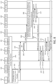
- FIG. 7A-FIG. 7B shows a procedure of a UE initiated switch from unicast to multicast.
- Step 220 as a pre-requisite step, a unicast session is established, and data is transferred over the unicast session between UE 201 and AF 210 through the network.
- the data is sent from the UPF 205 to the UE 201 via a PDU Session.
- Step 222 UE 201 sends a NAS message (e.g., a PDU session establishment/modification or service request) to AMF 203, which may include an indication of a delivery mode switch request.
- the message may include the following information which may have been received in step 221.
- UE ID such as 5G-GUTI and SUPI.
- the Information may include PDU session ID and flow descriptor for the current unicast data transfer.
- the flow descriptor may be an IP 5-tuple.
- Information may include DNN which indicate the data network that originates and/or terminates the data for multicast and unicast.
- S-NSSAI(s) which indicate the network slice that UE 201 connects to for the unicast data transfer.
- Information may include application information such as application ID indicating which application data may be delivered by multicast/unicast. Moreover, this may include operating system ID (OSId) and operating system application IDs (OSAppId(s)).
- OSId operating system ID
- OSAppId(s) operating system application IDs
- QoS Information may include QoS information such as 5QI, QoS flow ID, maximum data rate, error rate, or maximum latency. Depending on whether the multicast session exists, these QoS information could be QoS parameters if it already exists, or the QoS requirements if there is no existing multicast session.
- Information may include desired time instant that UE 201 would like to start receiving data from multicast session, e.g., when the switch takes effect.
- the UE 201 provides additional credentials needed to establish or join the multicast service or group.
- Multicast request context may be optional information needed by NFs to determine whether the request meets local policies, e.g. predicted UE 201 route or location.
- More information may include multicast IP address which is the identity that identifies the multicast session/group. More information may include other MBS session context information UE 201 has such as MB-SMF address, S-NSSAI identifying the network slice that is serving the multicast session, multicast session service area, and maximum multicast data rate. More information may include TMGI identifying the multicast group that UE 201 wants to join. More information may include Multicast Session ID or Reference ID that was received in an advertisement for the Multicast session.
- Step 223 If AMF 203 does not know MBMF 207 information or UE 201 does not provide such information, AMF 203 may use a default MBMF or communicate with NSSF/UDM to receive assistance for determining and selecting MBMF 207.
- the new AMF 203 is responsible for handling the control signaling that are shown in FIG. 7A .
- Step 261b alternatively, NF may want to start the switch due to the reasons / triggers disclosed herein, such as the information or events (e.g., Events Triggering Switching from Unicast to Multicast).
- the information or events e.g., Events Triggering Switching from Unicast to Multicast.
- Step 262 AMF 203 sends UE(s) a NAS message to notify UE 201 the switch decision.
- the NAS message may be a UE configuration update message, which may include the following information: unicast session ID, QoS parameters (e.g., data rate, latency and error rate), application information that may be switched to multicast, TMGI, multicast IP address, source IP address, MBS session ID and context information (such as MBS service area), or starting time instant of the switch.
- QoS parameters e.g., data rate, latency and error rate
- application information that may be switched to multicast
- TMGI multicast IP address
- source IP address source IP address
- MBS session ID and context information such as MBS service area
- AMF 203 may perform the step 263.
- RAN node 202 sends an RRC message to notify UE 201 that it decides to initiate the switch, and then UE 201 initiates the switch following the procedures presented above.
- RAN node 202 sends an N2 message to AMF 203 requesting network to initiate the switch, which then follows the procedure presented herein, such as FIG. 8 with regard to Network Initiated Procedure.
- RAN node 202 may also indicate the cause of the switch, such as limited unicast radio resource or UE 201 entering multicast service area. This option may be useful for the scenario that multiple UEs served by the RAN node 202 are switching to multicast for the same application.
- RAN node 202 may provide UE ID to network for each of UEs involved, and request network to assign a TMGI to form a group if multicast group is not formed yet.
- This section presents the procedures of switching data transmission from multicast to unicast.
- a UE 201 may request to switch from multicast to unicast for an application due to one of the following five reasons, among other things.
- This measurement could be from the application layer, or at the transport layer.
- a gaming application prompts a user to continue the gaming session after all other members left the multicast session.
- a user could intentionally/manually exit a broadcast or multicast group (e.g. based on a GUI request).
- UE subscription profile is changed to not allow UE 201 to use the MBS service.
- the switch from multicast to unicast could be initiated by the core network entity, including a request from AF 210 or external SCS/AS via NEF 211. This request may be initiated for the following three reasons, among other reasons.
- the content provider finds that the number of users receiving data on the multicast session decreases, and it becomes less efficient to continue multicast from resource management aspect.
- the content provider finds out that the data transfer performance degrades and cannot meet requirement at application layer, it may decide to unicast data with more performance guarantee.
- the network functions such as MB-SMF 208, MB-UPF 209, AMF 203, or NWDAF finds or predicts that the data transfer performance within core network cannot meet requirement, or that UE 201 moves out of MBS session service area.
- the network may switch the UE 201 to using unicast session for better mobility handling of the traffic in case the UE 201 moves.
- the switch from multicast to unicast could be initiated by the RAN node 202 as well.
- RAN node 202 measures some parameters (e.g., data rate, error rate, or latency) for the ongoing multicast session and finds that the performance is below a threshold or may degrade below a threshold.
- the RAN node 202 may determine the need to switch the application data transfer to unicast session that can guarantee the performance requirements.
- triggers to switch flows from unicast to multicast and triggers to switch flows from multicast to unicast. It should be understood that although a particular trigger might be discussed in the context of switching a flow from unicast to multicast/broadcast, it can also apply to switching a flow from multicast/broadcast to unicast. It should also be understood that although a particular trigger might be discussed in the context of switching a flow from multicast/broadcast to unicast, it can also apply to switching a flow from unicast to multicast/broadcast.
- a UE 201 wants to switch the data transfer from a multicast session to a unicast session, different approaches can be used, such as control plane method or user plane method.
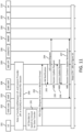
- FIG. 10 shows the procedure which UE 201 sends the switch request over the control plane path.
- Step 270 as a pre-requisite step, a multicast session is established, and UE 201 is receiving data over the multicast session from content provider.
- Step 271 at some point, UE 201 decides to switch data transmission to unicast.
- Step 272 UE 201 sends a NAS message (e.g., service request, or session establishment request/update) to AMF 203 indicating that it intends to switch to unicast.
- NAS message e.g., service request, or session establishment request/update
- UE 201 may provide the following information.
- the information may include UE ID, such as 5G-GUTI, SUPI, or S-NSSAI(s).
- UE ID such as 5G-GUTI, SUPI, or S-NSSAI(s).
- the information may include Unicast session ID and session context, such as QoS profile, session type, session continuity mode, or service continuity mode.
- the information may include DNN which may indicate the data network that originates or terminates the data for multicast and unicast.
- the information may include application information, such as application ID indicating which application data may be delivered by multicast/unicast. Moreover, this may include of OSId or OSAppId(s).
- the information may include desired (e.g., threshold) time instant that UE 201 would like to start receiving data from multicast session, e.g., when the switch takes effective. This could be associated with a certain time period, indicating that UE 201 may receive the data over multicast during the time period.
- desired time instant e.g., threshold
- the information may include External group ID, which may be an application layer ID that may be converted to internal group by network to identify the multicast group for the UE 201.
- External group ID may be an application layer ID that may be converted to internal group by network to identify the multicast group for the UE 201.
- the information may include, if MBS session for multicast is already established, UE 201 also provides the TMGI, multicast IP address, or MBS session ID information.
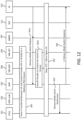
- FIG. 12 shows the procedure of network-initiated switch from multicast to unicast including the scenario that AF 210 initiates the procedure by sending request to NF.
- the information may include source IP address of the application data flow.
- the information may include desired time instant indicating when the unicast transmission starts.
- Step 301b in addition to trigger by AF 210, NFs may also decide to switch from multicast to unicast.
- Step 302 Network performs steps 273 ⁇ step 283 as shown in FIG. 10 to enable the switch from multicast to unicast.
- Step 303 AMF 203 sends delivery mode switch notification to UE 201(s) so that UE 201 may prepare for the switch.
- AMF 203 provides the following information to UE 201: unicast session ID, context information, QoS parameters, application information that may be switched to unicast, TMGI, multicast IP address, source IP address, MBS session ID, or starting time instant of the switch.
- Step 304 at last, network returns response to requesting AF 210.
- RAN node 202 wants to initiate the switch from multicast to unicast transmission for an application data flow, there are two options that are similar to the methods presented above, e.g. the RAN node 202 may send a notification message to individual UE to start switch or send a N2 message to AMF 203 to start the switch.
- This new QoS parameter may be named for example "Delivery Mode Control” or "Delivery Notification control.”
- the evolved notification control parameter or the new Delivery Mode control parameter may be used by the core network (e.g., a network server or other entity) to indicate whether notifications are requested from the NG-RAN when QoS requirement can no longer be met using the currently configured delivery mode, or to request delivery mode switch from MBMS user service (Multicast/Broadcast) to Unicast service, or to request delivery mode switch from unicast service to MBMS user service (Multicast/Broadcast).
- the AMF 203/SMF 204 may forward the notification to the PCF 206 or to the BM-SC/MBMF 207.
- the BM-SC, or the BM-SC in collaboration with the SMF 204 reconfigures the UE 201 with a new delivery mode using NAS signaling.
- the core network may also reconfigures the RAN accordingly to align with the new delivery mode configured into the UE 201.
- RAN node 202 may send a notification message to MB-UPF 209 through the N3 tunnel indicating to the MB-UPF 209 that no UE 201 under the RAN node 202 is still in the multicast group (e.g., receiving the application data over the multicast session), so that the MB-UPF 209 may stop sending the multicast application data over the N3 tunnel to this RAN node 202 in the future.
- the "source” is the RAN node that is currently connected with the UE and provides the UE access to the network
- the "target” is the RAN node anticipated or desired for UE to connect with to provide the UE access to the network.
- the UE 201 or source RAN node may trigger the delivery mode switch procedure along with the handover procedure. This trigger may be because the target RAN node does not support MBS service or UE 201 is out of an MBS service area.
- an NF such as AMF 203, MBMF, or MB-SMF 208/SMF 204 may trigger the switch as well after being notified by the source RAN node about the handover.
- the SMF 204 may find out that the target RAN node is out of MBS service area when initiating the PDU session establishment or modification procedure.
- the MBSF may trigger the switch.
- the UE 201 receives the multicast data over an MBS PDU session through the source RAN node. After a switch to individual traffic delivery method, the UE 201 may receive the data over a PDU session through the target RAN node.
- Significant issues may include the following. A first issue with regard to how to link the MBS PDU session for shared delivery method and the PDU session for individual delivery method to make sure the QoS requirement is met. Or a second issue with regard to how to prevent the potential data loss during the handover/switch process.
- the SMF 204 may send the QoS mapping information between MBS session and PDU session as well as the PDU session information to the source RAN node using N2 SM message, so that the source RAN node may be able to map the QoS of MBS session to QoS of PDU session. This may be used by the source RAN node during the switch especially when the target RAN node does not support MBS service, e.g., it is not aware of any MBS QoS.
- source RAN node may tell the target RAN node about the QoS requirement of one or more QoS flows in PDU session for individual delivery method. Then the target RAN node may be able to adjust RAN resource for data transfer to UE 201 based on the QoS of the PDU session for the individual delivery.
- the source RAN node could transfer such information directly to the target RAN node via Xn interface or via N2 interface to AMF 203 which forwards the information to the target RAN node.
- the PDU session information may include PDU session ID, QFIs, QoS parameters of the QFIs such as 5QI, max data rate, max aggregate flow rate, or QoS characteristics, such as error rate or latency.
- UE 201 may also be provided with such QoS mapping, so it could provide the QoS requirement of the PDU session established for the individual traffic delivery based on the mapping to the target RAN node.
- the benefit is that the UE 201 could provide the mapping at the beginning of handover process to the target RAN node, so that the switch process could be done faster.
- MB-SMF 208/SMF 204 managing the MBS session or the source RAN node could provide the QoS mapping to the UE 201.
- the QoS mapping information may include QFI of MBS PDU session and QFI of PDU session for the individual traffic delivery with the same QoS requirement, 5QI of MBS PDU session and 5QI of PDU session for the individual traffic delivery.
- handover usually completes before the delivery mode switch process. Regardless whether the target RAN node supports MBS service or not, during the time period between completion of handover and completion of switch, the UE 201 may not be able to receive data because handover is done while the switch is not finished yet, e.g., the PDU session for individual traffic delivery is not established yet or not activated yet.
- One possible approach is to let source RAN node continue to receive and store the MBS data during the time period and forwards the data to the target RAN node.
- the target RAN node When the PDU session is ready for individual traffic delivery to UE 201, e.g., switch is complete, the target RAN node notifies the source RAN node, and the source RAN node stops MBS data storage and forwarding.
- the source RAN node and target RAN node may exchange data storing and forwarding information during the handover process.
- the information may include the following: how often the source RAN node should forward the data, the max amount of data the source RAN node may store for the UE 201 after handover, how long the source RAN node may keep the data if it does not hear anything from the target RAN node, what forwarding mechanism is used for data forwarding.
- the possible forwarding mechanism could be directly to the target RAN node or to the UPF 205 which then sends the data to the target RAN node via N3 tunnel, source RAN node pushes the stored data or target RAN node retrieves the data from source RAN node.
- the 2 RAN nodes may need to establish a data forwarding channel which is transparent to 5GC.
- An alternative method is to make the PDU session ready for the individual delivery during the handover.
- 5GC needs to establish or modify the PDU session for the individual delivery during the handover.
- target RAN node may be able to deliver the data to UE 201 using the individual delivery method over the associated PDU session.
- the session management process may be integrated into the handover process.
- the source RAN node supports the MBS service
- the same approach disclosed in previous paragraphs can be applied, e.g., the source RAN node is provided with QoS mapping between PDU session and MBS session and the MBS session information, so that the source RAN node is able to tell the target RAN node how to set up the RAN resource to deliver the multicast data to the UE 201 to meet the QoS requirement.
- the source RAN node does not support MBS service, the source RAN node is not able to map the QoS of individual delivery method to the QoS of shared delivery.
- UE 201 may be provided with the QoS mapping information, and thus UE 201 may provide the target RAN node with the necessary QoS information to configure the RAN resource to send multicast cast.
- An alternative method is to handover the PDU session associated with the source RAN node for individual delivery method to the target RAN node.
- the target RAN node may have two N3 tunnels: 1) one N3 tunnel may be used for individual delivery before the switch, and 2) another N3 tunnel may be used for shared delivery after the switch. It is possible that different UPFs terminate the N3 tunnels.
- the application server or AF 210 may be aware of these changes with the notification from 5GC, and send the data to the appropriate UPF 205 accordingly.
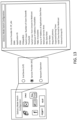
- the parameters used in delivery mode switch process could be provisioned by the end user (UE), network operator, or application content provider through a user interface.
- the switching UE, content provider or network operator could retrieve and display the statistics through the user interface.
- the user interface may be implemented for configuring or programming those parameters with default values, as well as enabling or disabling the switch process.
- An exemplary user interface is shown in FIG. 13 .
- NF Network Function
- a NF is a processing function in a network, which has defined functional behavior and defined interfaces.
- a NF can be implemented either as a network element on a dedicated hardware, or as a software instance running on a dedicated hardware, or as a virtualized function instantiated on an appropriate platform, e.g. on a cloud infrastructure.
- MBMS Bearer Service The service provided by the PS Domain to MBMS User Services to deliver IP multicast datagrams to multiple receivers using minimum network and radio resources.
- MBMS User Service The MBMS service provided to the end user by means of the MBMS Bearer Service and possibly other capabilities.
- MBS service area The area within which data of one or multiple MBS session(s) are sent.
- 5GC Individual MBS traffic delivery 5G CN may receive a single copy of MBS data packets and delivers separate copies of those MBS data packets to individual UEs via per-UE PDU sessions, hence for each such UE one PDU session is required to be associated with a multicast session
- 5GC shared MBS traffic 5G CN may receive a single copy of MBS data packets and delivery delivers a single copy of those MBS data packets to a RAN node.
- the RAN node For 5GC shared MBS traffic delivery, the RAN node either delivers a single copy of MBS data packets over radio to a set of UEs (PTM) or delivers separate copies of MBS data packets over radio to individual UEs (PTP).
- 5GC 5G Core Network AF Application Function AMF Access and Mobility Management Function API Application Program Interface APN Access Point Name AS Application Server BM-SC Broadcast-Multicast Service Center CM Connection Management CN Core Network CP Control Plane DL Downlink EPC Evolved Packet Core EPS Evolved Packet System GUTI Globally Unique Temporary UE Identity HSS Home Subscriber Server IE Information Element IMSI International Mobile Subscriber Identity LTE Long Term Evolution eMBMS Evolved Multimedia Broadcast Multicast Service MBMF Multicast and Broadcast Management Function MBS Multicast/Broadcast Service MM Mobility Management MME Mobility Management Entity MooD MBMS operation on Demand NAS Non-Access Stratum NEF Network Exposure Function NF Network Function
- FIG. 6 - FIG. 12 may be logical entities.
- the steps may be stored in a memory of, and executing on a processor of, a device, server, or computer system such as those illustrated in FIG. 1F or FIG. 1G . Skipping steps, combining steps, or adding steps between exemplary methods disclosed herein (e.g., FIG. 6 - FIG. 12 ) is contemplated.
- Computer readable storage media includes volatile and nonvolatile, removable and non-removable media implemented in any non-transitory (e.g., tangible or physical) method or technology for storage of information, but such computer readable storage media do not include signals.
- Computer readable storage media include, but are not limited to, RAM, ROM, EEPROM, flash memory or other memory technology, CD-ROM, digital versatile disks (DVD) or other optical disk storage, magnetic cassettes, magnetic tape, magnetic disk storage or other magnetic storage devices, or any other tangible or physical medium which may be used to store the desired information and which may be accessed by a computing system.
- a method, system, computer readable storage medium, or apparatus provides for determining a triggering event has occurred at one or more of a user device (e.g., UE), a network device (e.g., core network device), content provider system, or RAN node, wherein the triggering event indicates a need to switch between a first one and a second one of unicast mode, multicast mode, and broadcast mode; and initiating, based upon the occurrence of the triggering event, a switch from the first one of the unicast mode, the multicast mode, and the broadcast mode to the second one of the unicast mode, the multicast mode, and the broadcast mode for transmitting data to the user device.
- a user device e.g., UE
- a network device e.g., core network device
- content provider system e.g., or RAN node
- a system, computer readable storage medium, or apparatus provides for switching between at least two unicast mode, multicast mode, and broadcast mode for transmitting data to a user device over a 5G network. Further comprises: transmitting, from the user device and to a network entity, a request to switch from unicast mode to multicast node; performing, using the network entity, a MBS service authorization and MBS session management configuration; notifying an application server and RAN node about change in mode from unicast mode to multicast mode from the user device; or receiving, by the user device, information from the network for joining a multicast group.
- the request may include one or more of types of data comprising: an identifier of the user device; a session identifier and flow descriptor for the current unicast data transfer; an indication of the data network that originates and/or terminates the data for multicast and unicast; an indication of the network slice that the user device uses for the unicast data transfer; an application identifier indicating application data will be delivered by multicast/unicast; multicast session identifier; Quality of Service information; a changeover time identifier; multicast credentials: the UE provides additional credentials needed to establish or join the multicast service or group; a multicast request context; a multicast IP address: the identity that identifies the multicast session/group; other MBS session context information; a TMGI identifying the multicast group that UE wants to join; or a Multicast Session identifier or Reference identifier.
- types of data comprising: an identifier of the user device; a session identifier and flow descriptor for the current unicast data transfer
- the response message that comprises the indication of authorization for the requesting UE to use the MBS further comprises a Temporary Mobile Group Identity (TMGI) or internet protocol multicast address to identify the multicast group.
- Received information may include QoS mapping information between MBS session and PDU session, and other session information.
- Delivery mode switching information may be received via an N2 interface from a source RAN node. After handover completes but switch not completed, source RAN node may store the multicast data temporarily, and forward the data to the target RAN node after switch is completed.
- the request may be a NAS request message.
- a system, computer readable storage medium, or apparatus provides for determining a triggering event has occurred at a user device; or initiating, by the user device and based upon the occurrence of the triggering event, a switch from the unicast mode to the multicast mode.
- a system, computer readable storage medium, or apparatus provides for transmitting, from the user device and to a network entity, a request to switch from unicast mode to multicast node; performing, using the network entity, a MBS service authorization and MBS session management configuration; notifying an application server and RAN node about change in mode from unicast mode to multicast mode from the user device; or receiving, by the user device, information from the network for joining a multicast group.
- a method, system, computer readable storage medium, or apparatus provides for receiving, by a network function, a Non-Access Stratum (NAS) message from a requesting user equipment (UE); sending, by the network function, a request to a multicast and broadcast management function (MBMF) to determine whether the requesting UE is authorized to use the multicast service or multicast/broadcast service (MBS); in response to sending the request to the MBMF, receiving a response message that comprises an indication of authorization for the requesting UE to use the multicast service or multicast/broadcast service (MBS); determining that an MBS session is not available; based on the MBS session not available and the indication of authorization, sending an MBS session establishment message or modification message; in response to the sending of the MBS session establishment message or modification message, receiving a response with multicast/broadcast-user plane function (MB-UPF) information; or based on the MB-UPF information, sending a message (e.g., N2 message) to a radio access node to notify
- Unicast means 5GC sends 1 copy of packet to individual UE. So, multicast refers to 5GC sends 1 copy of packet to multiple UEs that joins the group. From RAN perspective, multicast from 5GC to UE could be done by unicast between RAN and UE or multicast between RAN and UE.
- the method, system, apparatus, or computer-readable storage medium may provide for detecting a triggering event; and based on the triggering event, initiating the switch from the unicast mode to the multicast mode, which comprises the sending the request to the multicast and broadcast management function (MBMF) to determine whether the requesting UE is authorized to use the multicast service or multicast/broadcast service (MBS).
- MBMF broadcast management function
- the triggering may occur at one or more of the requesting UE or a RAN node.
- the triggering event may be any number of events disclosed herein, which may include reaching a threshold number with regard to the disclosed information, which may be one type of information (e.g., error rate) or a combination of information (e.g., error rate and bandwidth).
- the method, system, apparatus, or computer-readable storage medium may provide for receiving information via an N2 interface from a source RAN node; and in response to receiving the information via the N2 interface, forwarding the information to a target RAN node. All combinations in this paragraph and the below paragraph (including the removal or addition of steps) are contemplated in a manner that is consistent with the other portions of the detailed description.
- a method, system, computer readable storage medium, or apparatus provides for receiving data from a radio access node on a unicast packet data unit session; determining to use multicast for data transfer; in response to the determining to use multicast for data transfer, sending a message to request a delivery mode switch from unicast to multicast; based on the message to request the delivery mode switch from unicast to multicast, receiving a NAS message carrying a delivery mode switch response; and sending an application layer signal to notify a network device about an upcoming switch from a unicast to a multicast session.
- the application layer signal to notify the network device indicates when the multicast session will start and for which application, while the unicast data transfer continues. In response to sending the application layer signal, receiving data over the multicast session.
Landscapes
- Engineering & Computer Science (AREA)
- Computer Networks & Wireless Communication (AREA)
- Signal Processing (AREA)
- Multimedia (AREA)
- Mobile Radio Communication Systems (AREA)
- Data Exchanges In Wide-Area Networks (AREA)
Applications Claiming Priority (3)
| Application Number | Priority Date | Filing Date | Title |
|---|---|---|---|
| US202062975858P | 2020-02-13 | 2020-02-13 | |
| PCT/US2021/017563 WO2021163260A1 (en) | 2020-02-13 | 2021-02-11 | Methods of delivery mode switch for multicast and broadcast service in a 5g network |
| EP21709855.7A EP4104461B1 (de) | 2020-02-13 | 2021-02-11 | Verfahren zur umschaltung des bereitstellungsmodus für multicast- und broadcast-dienste in einem 5g-netzwerk |
Related Parent Applications (2)
| Application Number | Title | Priority Date | Filing Date |
|---|---|---|---|
| EP21709855.7A Division EP4104461B1 (de) | 2020-02-13 | 2021-02-11 | Verfahren zur umschaltung des bereitstellungsmodus für multicast- und broadcast-dienste in einem 5g-netzwerk |
| EP21709855.7A Division-Into EP4104461B1 (de) | 2020-02-13 | 2021-02-11 | Verfahren zur umschaltung des bereitstellungsmodus für multicast- und broadcast-dienste in einem 5g-netzwerk |
Publications (2)
| Publication Number | Publication Date |
|---|---|
| EP4580256A2 true EP4580256A2 (de) | 2025-07-02 |
| EP4580256A3 EP4580256A3 (de) | 2025-08-27 |
Family
ID=74856953
Family Applications (2)
| Application Number | Title | Priority Date | Filing Date |
|---|---|---|---|
| EP21709855.7A Active EP4104461B1 (de) | 2020-02-13 | 2021-02-11 | Verfahren zur umschaltung des bereitstellungsmodus für multicast- und broadcast-dienste in einem 5g-netzwerk |
| EP25176376.9A Pending EP4580256A3 (de) | 2020-02-13 | 2021-02-11 | Verfahren zur liefermodusumschaltung für multicast- und broadcast-dienst in einem 5g-netzwerk |
Family Applications Before (1)
| Application Number | Title | Priority Date | Filing Date |
|---|---|---|---|
| EP21709855.7A Active EP4104461B1 (de) | 2020-02-13 | 2021-02-11 | Verfahren zur umschaltung des bereitstellungsmodus für multicast- und broadcast-dienste in einem 5g-netzwerk |
Country Status (4)
| Country | Link |
|---|---|
| US (2) | US20230345310A1 (de) |
| EP (2) | EP4104461B1 (de) |
| CN (2) | CN115486101B (de) |
| WO (1) | WO2021163260A1 (de) |
Families Citing this family (30)
| Publication number | Priority date | Publication date | Assignee | Title |
|---|---|---|---|---|
| CN111510964B (zh) * | 2019-01-31 | 2021-09-07 | 华为技术有限公司 | 一种通信方法及装置 |
| CN114902731A (zh) * | 2020-01-06 | 2022-08-12 | Oppo广东移动通信有限公司 | 一种业务切换方法、终端及网络设备 |
| EP4106486A4 (de) * | 2020-02-14 | 2024-03-20 | KT Corporation | Verfahren und vorrichtung zur verarbeitung von mbs-daten |
| CN113438692B (zh) * | 2020-03-23 | 2023-10-27 | 维沃移动通信有限公司 | 传输模式转换指示方法、接入网设备及终端设备 |
| WO2021191802A1 (en) * | 2020-03-23 | 2021-09-30 | Telefonaktiebolaget Lm Ericsson (Publ) | Ran-5gc interactions for session join, session start, session leave, session stop, and session delete for 5g multicast broadcast services |
| EP4111713B1 (de) * | 2020-03-25 | 2025-10-15 | ZTE Corporation | Aufbau und verwaltung einer multicast- oder broadcast-sitzung |
| KR20210120391A (ko) * | 2020-03-26 | 2021-10-07 | 삼성전자주식회사 | Mbs 설정의 시작 시점을 위한 방법 및 장치 |
| JP7583059B2 (ja) * | 2020-04-10 | 2024-11-13 | オッポ広東移動通信有限公司 | セッション処理方法、デバイス及び記憶媒体 |
| CN113573248B (zh) * | 2020-04-28 | 2023-06-20 | 华为技术有限公司 | 用于传输数据的方法与装置 |
| CN113645670B (zh) * | 2020-05-11 | 2025-05-27 | 苹果公司 | 5g新无线电的组播广播服务 |
| CN113676846B (zh) * | 2020-05-15 | 2023-04-11 | 大唐移动通信设备有限公司 | 一种传输方式确定方法、装置、设备及存储介质 |
| CN113784384B (zh) * | 2020-06-09 | 2024-03-08 | 维沃移动通信有限公司 | 模式切换方法、终端及网络侧设备 |
| CN114071367B (zh) * | 2020-08-04 | 2022-09-09 | 大唐移动通信设备有限公司 | 单播多播转换方法、装置及处理器可读存储介质 |
| WO2022029633A1 (en) * | 2020-08-07 | 2022-02-10 | Telefonaktiebolaget Lm Ericsson (Publ) | 5g multicast/broadcast multimedia subsystem (5mbs) individual delivery |
| WO2022101360A1 (en) * | 2020-11-13 | 2022-05-19 | Telefonaktiebolaget Lm Ericsson (Publ) | Method, apparatus and computer program product for providing service continuity for multicast and broadcast service |
| JPWO2022153990A1 (de) * | 2021-01-13 | 2022-07-21 | ||
| CN114938494B (zh) * | 2021-02-05 | 2024-06-18 | 华为技术有限公司 | 通信方法及装置 |
| CN114915917B (zh) * | 2021-02-10 | 2024-06-28 | 华为技术有限公司 | 传输多播业务的方法及装置 |
| CN112954614B (zh) * | 2021-02-10 | 2023-05-12 | 腾讯科技(深圳)有限公司 | 用于实现多播广播业务切换的方法及相关设备 |
| CN112954613B (zh) * | 2021-02-10 | 2023-05-12 | 腾讯科技(深圳)有限公司 | 用于实现多播广播业务切换的方法及相关设备 |
| WO2022179525A1 (en) * | 2021-02-23 | 2022-09-01 | Telefonaktiebolaget Lm Ericsson (Publ) | Method and apparatus for authentication |
| KR20220135982A (ko) * | 2021-03-31 | 2022-10-07 | 삼성전자주식회사 | 셀룰라 통신 시스템에서 사용자 장치로 mbs 데이터를 제공하기 위한 방법 및 장치 |
| CN115278547A (zh) * | 2021-04-30 | 2022-11-01 | 华为技术有限公司 | 通信方法及装置 |
| CN115835317B (zh) * | 2021-09-17 | 2025-10-28 | 维沃移动通信有限公司 | 切换业务的方法、装置和网络设备 |
| US11758368B2 (en) * | 2021-09-29 | 2023-09-12 | Oracle International Corporation | Methods, systems, and computer readable media for supporting mobile originated data multicasting in a communications network |
| WO2023060607A1 (zh) * | 2021-10-15 | 2023-04-20 | Oppo广东移动通信有限公司 | 业务接入方法、装置、设备及存储介质 |
| KR20230139523A (ko) * | 2022-03-28 | 2023-10-05 | 삼성전자주식회사 | 무선 통신 시스템에서 브로드캐스트 서비스를 제공하는 방법 및 장치 |
| EP4515888A4 (de) * | 2022-04-29 | 2025-08-13 | Ericsson Telefon Ab L M | Verfahren und vorrichtungen zur gemeinsamen bereitstellung von ip-multicast |
| US12363567B2 (en) * | 2022-06-30 | 2025-07-15 | Fortinet, Inc. | Capturing multiuser data packets by grouping access points on a wireless network |
| WO2025054830A1 (en) * | 2023-09-12 | 2025-03-20 | Shenzhen Tcl New Technology Co., Ltd. | Wireless communication system and wireless communication method for media content delivery |
Family Cites Families (21)
| Publication number | Priority date | Publication date | Assignee | Title |
|---|---|---|---|---|
| GB2485237A (en) * | 2010-11-08 | 2012-05-09 | Nec Corp | MBMS provided by unicast or broadcast/multicast in dependence on the number of interested users. |
| US9826502B2 (en) * | 2011-07-25 | 2017-11-21 | Qualcomm Incorporated | Managing handoff triggering between unicast and multicast services |
| US9445243B2 (en) * | 2013-03-22 | 2016-09-13 | Mediatek Inc. | Service continuity for group communication over LTE eMBMS |
| EP3079400B1 (de) * | 2014-01-03 | 2019-08-14 | Huawei Technologies Co., Ltd. | Benutzergerätweiterreichungsverfahren und basisstation |
| CN108886669B (zh) * | 2016-01-28 | 2021-09-14 | 诺基亚通信公司 | 广播和单播递送之间的流送服务的动态切换 |
| US20170374581A1 (en) * | 2016-06-23 | 2017-12-28 | Huawei Technologies Co., Ltd. | System and method for delivering unicast and broadcast traffic in a communication network |
| US10779163B2 (en) * | 2017-01-05 | 2020-09-15 | Huawei Technologies Co., Ltd. | Network architecture having multicast and broadcast multimedia subsystem capabilities |
| US10932095B2 (en) * | 2017-11-22 | 2021-02-23 | Huawei Technologies Co., Ltd. | Method and system for multicast and broadcast services |
| WO2019114939A1 (en) * | 2017-12-12 | 2019-06-20 | Nokia Solutions And Networks Oy | Method, system & apparatus for multicast session management in a 5g communication network |
| EP3725034B1 (de) * | 2017-12-12 | 2024-08-21 | Nokia Solutions and Networks Oy | Verfahren, system und vorrichtung für multicast-sitzungsverwaltung in einem 5g-kommunikationsnetz |
| CN110167190B (zh) * | 2018-02-14 | 2021-02-12 | 华为技术有限公司 | 会话建立方法和设备 |
| WO2019161927A1 (en) * | 2018-02-26 | 2019-08-29 | Nokia Technologies Oy | Multicast traffic area management and mobility for wireless network |
| CN110972078A (zh) * | 2018-09-30 | 2020-04-07 | 华为技术有限公司 | 多播/广播业务传输的方法、核心网网元和终端设备 |
| KR20210027976A (ko) * | 2019-09-03 | 2021-03-11 | 삼성전자주식회사 | 이동통신망에서 멀티캐스트 및 브로드캐스트 서비스를 제공하기 위한 방법 및 장치 |
| WO2021060823A1 (ko) * | 2019-09-27 | 2021-04-01 | 삼성전자 주식회사 | 무선통신시스템에서 데이터를 송수신하는 방법 및 장치 |
| US20210105196A1 (en) * | 2019-10-04 | 2021-04-08 | Huawei Technologies Co., Ltd. | Support group communications with shared downlink data |
| US11831458B2 (en) * | 2019-11-19 | 2023-11-28 | Intel Corporation | Provisioning of multicast and broadcast services with different quality of service levels |
| GB2592717A (en) * | 2019-12-23 | 2021-09-08 | Samsung Electronics Co Ltd | Network switching |
| US12200739B2 (en) * | 2020-01-10 | 2025-01-14 | Sharp Kabushiki Kaisha | Method and user equipment for multicast/broadcast service data reception |
| CN114982286B (zh) * | 2020-01-24 | 2024-09-20 | 高通股份有限公司 | 用于保持广播服务无线通信的装置和方法 |
| CN115039423B (zh) * | 2020-01-24 | 2024-10-11 | 高通股份有限公司 | 用于维持多播和/或广播服务无线通信的技术 |
-
2021
- 2021-02-11 US US17/904,022 patent/US20230345310A1/en active Pending
- 2021-02-11 EP EP21709855.7A patent/EP4104461B1/de active Active
- 2021-02-11 EP EP25176376.9A patent/EP4580256A3/de active Pending
- 2021-02-11 CN CN202180022215.1A patent/CN115486101B/zh active Active
- 2021-02-11 CN CN202511528646.1A patent/CN121174107A/zh active Pending
- 2021-02-11 WO PCT/US2021/017563 patent/WO2021163260A1/en not_active Ceased
-
2024
- 2024-07-10 US US18/768,713 patent/US20240365178A1/en active Pending
Also Published As
| Publication number | Publication date |
|---|---|
| EP4580256A3 (de) | 2025-08-27 |
| US20230345310A1 (en) | 2023-10-26 |
| CN115486101A (zh) | 2022-12-16 |
| CN121174107A (zh) | 2025-12-19 |
| US20240365178A1 (en) | 2024-10-31 |
| EP4104461A1 (de) | 2022-12-21 |
| CN115486101B (zh) | 2025-11-25 |
| WO2021163260A1 (en) | 2021-08-19 |
| EP4104461B1 (de) | 2025-06-18 |
Similar Documents
| Publication | Publication Date | Title |
|---|---|---|
| EP4104461B1 (de) | Verfahren zur umschaltung des bereitstellungsmodus für multicast- und broadcast-dienste in einem 5g-netzwerk | |
| KR102840530B1 (ko) | 동적 네트워크 능력 구성 | |
| US11696158B2 (en) | Network Data Analytics in a communications network | |
| KR102692951B1 (ko) | 5g 네트워크에서의 로컬 영역 데이터 네트워크(ladn)에 대한 접속들을 관리하는 방법들 | |
| US20230362960A1 (en) | 5g multicast-broadcast services (mbs) scheduling and bearer management | |
| US11825385B2 (en) | Method, system and apparatus for multicast session management in 5G communication network | |
| JP6646113B2 (ja) | 選択インターネットプロトコルトラフィックオフロードのパケットデータネットワーク調整変更 | |
| US20230388866A1 (en) | Multicast-broadcast services mobility and service continuity | |
| KR20180124033A (ko) | 네트워크 슬라이싱 동작 | |
| US20240172175A1 (en) | Method and appartuses for group paging for signal efficiency in 5g network | |
| CN117242892A (zh) | 无线承载重新配置 | |
| AU2022381190B2 (en) | Preservation of session context in a communications network | |
| US20240267247A1 (en) | Communication method, apparatus, and device |
Legal Events
| Date | Code | Title | Description |
|---|---|---|---|
| PUAI | Public reference made under article 153(3) epc to a published international application that has entered the european phase |
Free format text: ORIGINAL CODE: 0009012 |
|
| STAA | Information on the status of an ep patent application or granted ep patent |
Free format text: STATUS: THE APPLICATION HAS BEEN PUBLISHED |
|
| AC | Divisional application: reference to earlier application |
Ref document number: 4104461 Country of ref document: EP Kind code of ref document: P |
|
| AK | Designated contracting states |
Kind code of ref document: A2 Designated state(s): AL AT BE BG CH CY CZ DE DK EE ES FI FR GB GR HR HU IE IS IT LI LT LU LV MC MK MT NL NO PL PT RO RS SE SI SK SM TR |
|
| REG | Reference to a national code |
Ref country code: DE Ref legal event code: R079 Free format text: PREVIOUS MAIN CLASS: H04W0036000000 Ipc: H04W0004060000 |
|
| PUAL | Search report despatched |
Free format text: ORIGINAL CODE: 0009013 |
|
| AK | Designated contracting states |
Kind code of ref document: A3 Designated state(s): AL AT BE BG CH CY CZ DE DK EE ES FI FR GB GR HR HU IE IS IT LI LT LU LV MC MK MT NL NO PL PT RO RS SE SI SK SM TR |
|
| RIC1 | Information provided on ipc code assigned before grant |
Ipc: H04W 4/06 20090101AFI20250722BHEP Ipc: H04W 76/40 20180101ALI20250722BHEP Ipc: H04W 36/00 20090101ALI20250722BHEP |