EP4580247A1 - Datenfusionsverfahren und -vorrichtung sowie intelligente antriebsvorrichtung - Google Patents
Datenfusionsverfahren und -vorrichtung sowie intelligente antriebsvorrichtung Download PDFInfo
- Publication number
- EP4580247A1 EP4580247A1 EP22958444.6A EP22958444A EP4580247A1 EP 4580247 A1 EP4580247 A1 EP 4580247A1 EP 22958444 A EP22958444 A EP 22958444A EP 4580247 A1 EP4580247 A1 EP 4580247A1
- Authority
- EP
- European Patent Office
- Prior art keywords
- camera
- group
- data
- laser beam
- driving device
- Prior art date
- Legal status (The legal status is an assumption and is not a legal conclusion. Google has not performed a legal analysis and makes no representation as to the accuracy of the status listed.)
- Pending
Links
Images




Classifications
-
- G—PHYSICS
- G01—MEASURING; TESTING
- G01S—RADIO DIRECTION-FINDING; RADIO NAVIGATION; DETERMINING DISTANCE OR VELOCITY BY USE OF RADIO WAVES; LOCATING OR PRESENCE-DETECTING BY USE OF THE REFLECTION OR RERADIATION OF RADIO WAVES; ANALOGOUS ARRANGEMENTS USING OTHER WAVES
- G01S17/00—Systems using the reflection or reradiation of electromagnetic waves other than radio waves, e.g. lidar systems
- G01S17/86—Combinations of lidar systems with systems other than lidar, radar or sonar, e.g. with direction finders
-
- G—PHYSICS
- G01—MEASURING; TESTING
- G01S—RADIO DIRECTION-FINDING; RADIO NAVIGATION; DETERMINING DISTANCE OR VELOCITY BY USE OF RADIO WAVES; LOCATING OR PRESENCE-DETECTING BY USE OF THE REFLECTION OR RERADIATION OF RADIO WAVES; ANALOGOUS ARRANGEMENTS USING OTHER WAVES
- G01S17/00—Systems using the reflection or reradiation of electromagnetic waves other than radio waves, e.g. lidar systems
- G01S17/02—Systems using the reflection of electromagnetic waves other than radio waves
- G01S17/06—Systems determining position data of a target
- G01S17/42—Simultaneous measurement of distance and other co-ordinates
-
- G—PHYSICS
- G01—MEASURING; TESTING
- G01S—RADIO DIRECTION-FINDING; RADIO NAVIGATION; DETERMINING DISTANCE OR VELOCITY BY USE OF RADIO WAVES; LOCATING OR PRESENCE-DETECTING BY USE OF THE REFLECTION OR RERADIATION OF RADIO WAVES; ANALOGOUS ARRANGEMENTS USING OTHER WAVES
- G01S17/00—Systems using the reflection or reradiation of electromagnetic waves other than radio waves, e.g. lidar systems
- G01S17/88—Lidar systems specially adapted for specific applications
- G01S17/89—Lidar systems specially adapted for specific applications for mapping or imaging
-
- G—PHYSICS
- G01—MEASURING; TESTING
- G01S—RADIO DIRECTION-FINDING; RADIO NAVIGATION; DETERMINING DISTANCE OR VELOCITY BY USE OF RADIO WAVES; LOCATING OR PRESENCE-DETECTING BY USE OF THE REFLECTION OR RERADIATION OF RADIO WAVES; ANALOGOUS ARRANGEMENTS USING OTHER WAVES
- G01S17/00—Systems using the reflection or reradiation of electromagnetic waves other than radio waves, e.g. lidar systems
- G01S17/88—Lidar systems specially adapted for specific applications
- G01S17/93—Lidar systems specially adapted for specific applications for anti-collision purposes
- G01S17/931—Lidar systems specially adapted for specific applications for anti-collision purposes of land vehicles
-
- G—PHYSICS
- G01—MEASURING; TESTING
- G01S—RADIO DIRECTION-FINDING; RADIO NAVIGATION; DETERMINING DISTANCE OR VELOCITY BY USE OF RADIO WAVES; LOCATING OR PRESENCE-DETECTING BY USE OF THE REFLECTION OR RERADIATION OF RADIO WAVES; ANALOGOUS ARRANGEMENTS USING OTHER WAVES
- G01S7/00—Details of systems according to groups G01S13/00, G01S15/00, G01S17/00
- G01S7/48—Details of systems according to groups G01S13/00, G01S15/00, G01S17/00 of systems according to group G01S17/00
- G01S7/481—Constructional features, e.g. arrangements of optical elements
- G01S7/4814—Constructional features, e.g. arrangements of optical elements of transmitters alone
- G01S7/4815—Constructional features, e.g. arrangements of optical elements of transmitters alone using multiple transmitters
-
- H—ELECTRICITY
- H04—ELECTRIC COMMUNICATION TECHNIQUE
- H04N—PICTORIAL COMMUNICATION, e.g. TELEVISION
- H04N23/00—Cameras or camera modules comprising electronic image sensors; Control thereof
- H04N23/90—Arrangement of cameras or camera modules, e.g. multiple cameras in TV studios or sports stadiums
Definitions
- ADAS advanced driver-assistance system
- various sensors are mounted on the vehicle to sense an ambient environment in a driving process of the vehicle, collect data, identify, detect, and track a static or moving object, and perform systematic calculation and analysis based on map data of a navigator, so that a driver can perceive a possible danger in advance. This effectively improves comfort and safety of vehicle driving.
- the sensors play an important role in assisted driving and autonomous driving of the intelligent vehicle, and are likened to "eyes" of the vehicle.
- the sensors include vision sensors such as a vehicle-mounted camera and radar sensors like a vehicle-mounted lidar and a vehicle-mounted ultrasonic radar.
- a lidar In a current multi-sensor fusion solution, a lidar has a fixed scan cycle, and a camera is triggered at a fixed frequency. In a scenario in which the lidar and the camera are fused, because a timestamp of the lidar does not match a timestamp of the camera, a fusion effect is usually poor, and consequently, an ambient environment of a vehicle cannot be accurately identified.
- This application discloses a data fusion method and apparatus, and an intelligent driving device, to improve a fusion effect of point cloud data obtained by a laser emitting apparatus through scanning and image data captured by a camera, so that an ambient environment of a vehicle is more accurately identified. This is more conducive to planning and implementation of an autonomous driving task.
- this application provides a data fusion method.
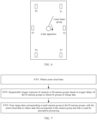
- the method includes: obtaining point cloud data, where the point cloud data is obtained through detection in a first scanning direction and a second scanning direction respectively based on a first laser beam group and a second laser beam group, and the first scanning direction is different from the second scanning direction; sequentially triggering exposure of cameras in the M camera groups based on trigger delays of the M camera groups to obtain M groups of image data, where cameras in a same camera group are exposed simultaneously, the trigger delay is related to a scan cycle of the first laser beam group and the second laser beam group, and M is a positive integer greater than or equal to 1; and fusing image data corresponding to each camera group in the M camera groups with the point cloud data to obtain data that corresponds to the camera group and that is used for perception processing.
- the M camera groups may be determined based on mounting locations of a plurality of cameras on an intelligent driving device.
- a traveling direction of the intelligent driving device is used as a reference.
- the point cloud data may be fused with image data of a camera group corresponding to a front field of view of the intelligent driving device, to improve a fusion effect of the point cloud data and the image data in the front field of view.
- a fusion effect of point cloud data and image data in a middle field of view and a fusion effect of point cloud data and image data in a rear field of view may also be improved. In this way, an ambient environment of the vehicle is more accurately identified. This is more conducive to planning and implementation of an autonomous driving task.
- the first data and the second data are spliced and fused for enhancement.
- point density of the point cloud data in this application is higher, and accuracy of identifying the ambient environment of the vehicle is higher.
- the first laser beam group and the second laser beam group are from a same laser emitting apparatus.
- the first laser beam group is from a first laser emitting apparatus
- the second laser beam group is from a second laser emitting apparatus.
- two laser beam groups can be used to perform covering scanning, so that the point density of the point cloud data is higher.
- the method further includes: determining a location of each camera group in the M camera groups; and determining a trigger delay of each camera group in the camera groups based on the scan cycle and the location of each camera group in the M camera groups.
- the M camera groups include a first camera group and a second camera group, a trigger delay of the first camera group is a first delay, and a trigger delay of the second camera group is a second delay.
- the sequentially triggering exposure of cameras in the M camera groups based on trigger delays of the M camera groups to obtain M groups of image data includes: starting a first timer to set an initial moment; when an interval between an indicated moment of the first timer and the initial moment is the first delay, triggering exposure of a camera in the first camera group to obtain image data corresponding to the first camera group; and when an interval between an indicated moment of the first timer and the initial moment is the second delay, triggering exposure of a camera in the second camera group to obtain image data corresponding to the second camera group.
- the M camera groups include a front-part group, a side-part group, and a rear-part group.
- the front-part group includes a first camera and a second camera, and the first camera and the second camera are disposed opposite to each other at a front part of the intelligent driving device.
- the side-part group includes a third camera and a fourth camera, and the third camera and the fourth camera are disposed opposite to each other on two sides of the intelligent driving device.
- the rear-part group includes a fifth camera and a sixth camera, and the fifth camera and the sixth camera are disposed opposite to each other at a rear part of the intelligent driving device.
- this application provides an intelligent driving device, including a computing platform and M camera groups.
- the computing platform is configured to: obtain point cloud data, where the point cloud data is obtained through detection in a first scanning direction and a second scanning direction respectively based on a first laser beam group and a second laser beam group, and the first scanning direction is different from the second scanning direction; sequentially trigger exposure of cameras in the M camera groups based on trigger delays of the M camera groups to obtain M groups of image data, where cameras in a same camera group are exposed simultaneously, the trigger delay is related to a scan cycle of the first laser beam group and the second laser beam group, and M is a positive integer greater than or equal to 1; and fuse image data corresponding to each camera group in the M camera groups with the point cloud data to obtain data that corresponds to the camera group and that is used for perception processing.
- the first laser beam group and the second laser beam group are from a same laser emitting apparatus.
- the M camera groups include a first camera group and a second camera group.
- a trigger delay of the first camera group is a first delay.
- a trigger delay of the second camera group is a second delay.
- the computing platform is further configured to: start a first timer to set an initial moment; when an interval between an indicated moment of the first timer and the initial moment is the first delay, trigger exposure of a camera in the first camera group to obtain image data corresponding to the first camera group; and when an interval between the indicated moment of the first timer and the initial moment is the second delay, trigger exposure of a camera in the second camera group to obtain image data corresponding to the second camera group.
- this application provides a chip.
- the chip includes a circuit, and the circuit is configured to implement the method according to any one of the first aspect or the possible implementations of the first aspect.
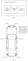
- the intelligent driving device 100 may further include one or more laser emitting apparatuses 103.
- the laser emitting apparatus 103 is configured to generate a first laser beam group and a second laser beam group.
- the first laser beam group and the second laser beam group are from a same laser emitting apparatus.
- the intelligent driving device 100 includes two laser emitting apparatuses 103, for example, a first laser emitting apparatus and a second laser emitting apparatus, the first laser emitting apparatus is configured to generate a first laser beam group, and the second laser emitting apparatus is configured to generate a second laser beam group.
- the first laser beam group and the second laser beam group are from different laser emitting apparatuses.
- the structure of the intelligent driving device in FIG. 1 is merely an example implementation in embodiments of this application.
- the intelligent driving device in embodiments of this application may further include more components as required.
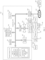
- the travel system 202 may include a component that provides power for the intelligent driving device 100 to move.
- the travel system 202 may include an engine 218, an energy source 219, a transmission apparatus 220, and a wheel/tire 221.
- the engine 218 may be an internal combustion engine, an electric motor, an air compression engine, or an engine combination of another type, for example, a hybrid engine including a gasoline engine and an electric motor, or a hybrid engine including an internal combustion engine and an air compression engine.
- the engine 218 converts the energy source 219 into mechanical energy.
- Examples of the energy source 219 include gasoline, diesel, another oil-based fuel, propane, another compressed gas-based fuel, ethanol, a solar panel, a battery, and another power source.
- the energy source 219 may also provide energy for another system of the intelligent driving device 100.
- the transmission apparatus 220 may transmit mechanical power from the engine 218 to the wheel 221.
- the transmission apparatus 220 may include a gearbox, a differential, and a drive shaft.
- the transmission apparatus 220 may further include another device, for example, a clutch.
- the drive shaft may include one or more shafts that may be coupled to one or more wheels 221.
- the sensor system 204 may include several sensors that sense information about an ambient environment of the intelligent driving device 100.
- the sensor system 204 may include a positioning system 222 (the positioning system may be a GPS system, a BeiDou system, or another positioning system), an inertial measurement unit (inertial measurement unit, IMU) 224, a radar 226, a laser rangefinder 228, and a camera 230.
- the sensor system 204 may further include sensors (for example, an in-vehicle air quality monitor, a fuel gauge, and an oil temperature gauge) in an internal system of the monitored intelligent driving device 100. Sensor data from one or more of these sensors may be used to detect an object and corresponding features (a location, a shape, a direction, a speed, and the like) of the object. Such detection and identification are key functions for safe operation of the autonomous intelligent driving device 100.
- the positioning system 222 may be configured to estimate a geographical location of the intelligent driving device 100.
- the IMU 224 is configured to sense and detect, based on inertia acceleration, a location and an orientation change of the intelligent driving device 100.
- the IMU 224 may be a combination of an accelerometer and a gyroscope.
- the radar 226 may sense, by using a radio signal, an object in the ambient environment of the intelligent driving device 100. In some embodiments, in addition to sensing an object, the radar 226 may be further configured to sense a speed and/or a moving direction of the object. In an example, the radar 226 may be the laser emitting apparatus 103 in FIG. 1 .
- the intelligent driving device 100 includes one lidar apparatus.
- the lidar apparatus includes two laser beam groups: a first laser beam group and a second laser beam group.
- the first laser beam group includes at least one laser beam
- the second laser beam group includes at least one laser beam.
- the first laser beam group performs detection in a first scanning direction to obtain first data
- the second laser beam group performs detection in a second scanning direction to obtain second data.
- the control system 206 controls operations of the intelligent driving device 100 and components of the intelligent driving device 100.
- the control system 206 may include various elements, including a steering system 232, a throttle 234, a brake unit 236, a sensor fusion algorithm 238, a computer vision system 240, a route control system 242, and an obstacle avoidance system 244.
- the steering system 232 may operate to adjust a heading direction of the intelligent driving device 100.
- the steering unit may be a steering wheel system.
- the brake unit 236 is configured to control the intelligent driving device 100 to decelerate.
- the brake unit 236 may slow down the wheel 221 through friction.
- the brake unit 236 may convert kinetic energy of the wheel 221 into a current.
- the brake unit 236 may alternatively reduce a rotational speed of the wheel 221 in another form, to control the speed of the intelligent driving device 100.
- the computer vision system 240 may operate to process and analyze an image captured by the camera 230, to identify an object and/or a feature in the ambient environment of the intelligent driving device 100, and/or process and analyze data information captured by the radar 226.
- the object and/or the feature may include a traffic signal, a road boundary, and an obstacle.
- the computer vision system 240 may use an object identification algorithm, a structure from motion (structure from motion, SFM) algorithm, video tracking, and another computer vision technology.
- the computer vision system 240 may be configured to: draw a map for an environment, track an object, estimate a speed of an object, and the like.
- the computer vision system 240 may be the computing platform 101 in FIG. 1 .
- the route control system 242 is configured to determine a traveling route of the intelligent driving device 100. In some embodiments, the route control system 242 may determine the traveling route for the intelligent driving device 100 with reference to data from the sensor fusion algorithm 238, the positioning system 222, and one or more predetermined maps.
- the obstacle avoidance system 244 is configured to identify, evaluate, and avoid or bypass, in another manner, a potential obstacle in the environment of the intelligent driving device 100.
- control system 206 may additionally or alternatively include a component other than those shown and described. Alternatively, some of the foregoing components may be removed.
- the intelligent driving device 100 interacts with an external sensor, another vehicle, another computer system, or a user by using the peripheral device 208.
- the peripheral device 208 may include a wireless communication system 246, a vehicle-mounted computer 248, a microphone 250, and/or a speaker 252.
- the wireless communication system 246 may communicate with, in a wireless manner, one or more devices directly or through a communication network.
- the wireless communication system 246 may use 3G cellular communication such as CDMA, EVD0, or GSM/GPRS, or 4G cellular communication such as LTE, or 5G cellular communication.
- the wireless communication system 246 may communicate with a wireless local area network (wireless local area network, WLAN) through Wi-Fi.
- the wireless communication system 246 may directly communicate with a device through an infrared link, Bluetooth, or ZigBee.
- the wireless communication system 246 may include one or more dedicated short-range communications (dedicated short-range communications, DSRC) devices. These devices may include public and/or private data communication between vehicles and/or roadside stations.
- DSRC dedicated short-range communications
- the power supply 210 may supply power to various components of the intelligent driving device 100.
- the power supply 210 may be a rechargeable lithium-ion or lead-acid battery.
- One or more battery packs of such a battery may be configured as a power supply for supplying power to various components of the intelligent driving device 100.
- the power supply 210 and the energy source 219 may be implemented together.
- the computer system 212 may include at least one processor 213.
- the processor 213 executes instructions 215 stored in a non-transient computer-readable medium like a memory 214.
- the computer system 212 may alternatively be a plurality of computing devices that control individual components or subsystems of the intelligent driving device 100 in a distributed manner.
- the processor may be away from the vehicle and communicate with the vehicle in a wireless manner. In other aspects, some of the processes described herein are performed by a processor disposed in the vehicle, and others are performed by a remote processor.
- the memory 214 may include the instructions 215 (for example, program logic), and the instructions 215 may be executed by the processor 213 to perform various functions of the intelligent driving device 100, including the functions described above.
- the memory 214 may also include additional instructions, including instructions for sending data to, receiving data from, interacting with, and/or controlling one or more of the travel system 202, the sensor system 204, the control system 206, and the peripheral device 208.
- the foregoing components are merely examples. During actual application, the components in the foregoing modules may be added or deleted according to an actual requirement. FIG. 4 should not be understood as any limitation on embodiments of this application.
- FIG. 5 is a diagram of a traveling control apparatus of an intelligent driving device according to an embodiment of this application.
- the traveling control apparatus is applied to FIG. 4 , and is equivalent to the computer system 212 shown in FIG. 4 .
- the traveling control apparatus may include a processor 213, and the processor 213 is coupled to a system bus 505.
- the processor 213 may be one or more processors, and each of the processors may include one or more processor cores.
- a memory 214 may store related data information, and the memory 214 is coupled to the system bus 505.
- a display adapter (display adapter) 507 may drive a display 509, and the display 509 is coupled to the system bus 505.
- the system bus 505 is coupled to an input/output (I/O) bus 513 through a bus bridge 501.
- I/O input/output
- the computer system 212 may be located away from the intelligent driving device and may communicate with the intelligent driving device in a wireless manner.
- some of the processes described in this specification are performed by a processor disposed in the intelligent driving device, and others are performed by a remote processor.
- the computer system 212 may communicate with a software deploying server 549 through a network interface 529.
- the network interface 529 is a hardware network interface, for example, a network adapter.
- a network 527 may be an external network like the Internet, or may be an internal network like the Ethernet or a virtual private network (virtual private network, VPN).
- the network 527 may alternatively be a wireless network, for example, a Wi-Fi network or a cellular network.
- a hard disk drive interface 531 is coupled to the system bus 505.
- the hard disk drive interface 531 is connected to a hard disk drive 533.
- a system memory 535 is coupled to the system bus 505. Data running in the system memory 535 may include an operating system 537 and an application 543 of the computer system 212.
- traveling control apparatus of an intelligent driving device in FIG. 5 is merely an example implementation in embodiments of this application.
- the traveling control apparatus applied to the intelligent driving device in embodiments of this application includes but is not limited to the foregoing structure.
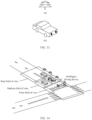
- FIG. 8a when the first laser beam group and the second laser beam group are from a same laser emitting apparatus, a top view of the first laser beam group and the second laser beam group is shown in FIG. 8a , and a side view of the first laser beam group and the second laser beam group is shown in FIG. 8b .
- FIG. 9a when the first laser beam group and the second laser beam group are from different laser emitting apparatuses, a top view of the first laser beam group and the second laser beam group is shown in FIG. 9a , and a side view of the first laser beam group and the second laser beam group is shown in FIG. 9b .
- That the first scanning direction is different from the second scanning direction may be understood as that rotation directions of the first laser beam group and the second laser beam group are different.
- the first scanning direction is a clockwise direction
- the second scanning direction is an anticlockwise direction.
- the first scanning direction is an anticlockwise direction
- the second scanning direction is a clockwise direction.
- Cameras in a same camera group are exposed simultaneously. For example, if a camera group includes a camera 1 and a camera 2, the camera 1 and the camera 2 are exposed simultaneously.
- a quantity of pieces of image data in each of the M groups of image data is the same as a quantity of cameras in each group.
- one camera group includes a camera 1 and a camera 2.
- the two pieces of image data are one group of image data, namely, image data corresponding to the camera group.
- M is a positive integer greater than or equal to 1.
- M may alternatively be a positive integer greater than or equal to 2.
- the M camera groups include a front-part group, a side-part group, and a rear-part group.
- the front-part group includes a first camera and a second camera, and the first camera and the second camera are disposed opposite to each other at the front part of the intelligent driving device.
- the side-part group includes a third camera and a fourth camera, and the third camera and the fourth camera are disposed opposite to each other on two sides of the intelligent driving device.
- the rear-part group includes a fifth camera and a sixth camera, and the fifth camera and the sixth camera are disposed opposite to each other at the rear part of the intelligent driving device.
- M 3.
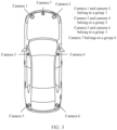
- Three camera groups are a group 1, a group 2, and a group 3.
- the intelligent driving device includes six cameras: a camera 1, a camera 2, a camera 3, a camera 4, a camera 5, and a camera 6.
- Each camera group includes two cameras.
- the M camera groups may further include a forward group.
- the forward group includes a seventh camera, and the seventh camera faces the traveling direction of the intelligent driving device.
- M 4.
- Four camera groups are a group 1, a group 2, a group 3, and a group 4.
- the intelligent driving device 100 includes six cameras: a camera 1, a camera 2, a camera 3, a camera 4, a camera 5, a camera 6, and a camera 7.
- Each camera group includes at least one camera. For details, refer to FIG. 3 .
- the M camera groups include a first camera group and a second camera group.
- a trigger delay of the first camera group is a first delay
- a trigger delay of the second camera group is a second delay.
- the sequentially triggering exposure of cameras in M camera groups based on trigger delays of the M camera groups to obtain M groups of image data includes: starting a first timer to set an initial moment; when an interval between an indicated moment of the first timer and the initial moment is the first delay, triggering exposure of a camera in the first camera group to obtain image data corresponding to the first camera group; and when an interval between an indicated moment of the first timer and the initial moment is the second delay, triggering exposure of a camera in the second camera group to obtain image data corresponding to the second camera group.
- the first delay may be 0, or may be another value.
- the first delay it may be understood that exposure of the camera in the first camera group is triggered when the first timer is started, to obtain the image data corresponding to the first camera group.
- the first laser beam group and the second laser beam group may perform detection respectively in the first scanning direction and the second scanning direction at the initial moment.
- the first laser beam group and the second laser beam group may perform detection respectively in the first scanning direction and the second scanning direction before or after the initial moment. This is not limited in embodiments of this application.
- the second delay may be greater than the first delay.
- the image data corresponding to the first camera group may be image data captured by all the cameras in the first camera group.
- the image data corresponding to the first camera group may be image data obtained by the camera 1 through exposure and image data obtained by the camera 2 through exposure. The same applies to the image data corresponding to the second camera group.
- first timers There may be one or more first timers.
- a quantity of first timers is the same as a quantity of cameras in a camera group. For example, if there are two cameras in the first camera group: a camera 1 and a camera 2, there are two first timers: a timer 1 and a timer 2.
- the timer 1 and the timer 2 may be synchronous. For example, the first delay is 0.
- the timer 1 and the timer 2 are started to trigger exposure of the camera 1 and the camera 2 in the first camera group to obtain the image data corresponding to the first camera group.
- the timer 1 triggers exposure of the camera 1 to obtain the image data corresponding to the camera 1
- the timer 2 triggers exposure of the camera 2 to obtain the image data corresponding to the camera 2.
- FIG. 13 is the image data captured by the camera 3, namely, image data in a middle field of view in the traveling direction of the intelligent driving device, and (b) in FIG. 13 is the image data captured by the camera 4, namely, image data in the middle field of view in the traveling direction of the intelligent driving device.
- Fusing the image data corresponding to each camera group in the M camera groups with the point cloud data to obtain the data that corresponds to the camera group and that is used for perception processing may be as follows: using the image data corresponding to each camera group in the M camera groups and the point cloud data as input data, and inputting the input data to a fusion perception algorithm, for example, a multi-modal fusion algorithm, to obtain the data that corresponds to the camera group and that is used for perception processing.
- a fusion perception algorithm for example, a multi-modal fusion algorithm
- (c) in FIG. 11 is a diagram of the point cloud data obtained by splicing the first data and the second data based on the environment in FIG. 10 .
- (a) in FIG. 12 is the image data captured by the camera 1 in the first camera group
- (b) in FIG. 12 is the image data captured by the camera 2 in the first camera group.
- the point cloud data in (c) in FIG. 11 may be fused with the image data captured by the camera 1 in the first camera group in (a) in FIG. 12 and the image data captured by the camera 2 in the first camera group in (b) in FIG.
- FIG. 14 is a diagram of a front field of view, a middle field of view, and a rear field of view of the intelligent driving device in the environment shown in FIG. 10 .
- a process is similar to a process of obtaining the fusion result of the point cloud data and the image data in the front field of view, and a fusion result of point cloud data and image data in the middle field of view in the traveling direction of the intelligent driving device and a fusion result of point cloud data and image data in the rear field of view in the traveling direction of the intelligent driving device may be obtained.
- the image data corresponding to each of the M camera groups may be fused.
- image data corresponding to at least two of the M camera groups may be used as input data, and the input data is input to a camera perception algorithm, for example, an image 2D target detection algorithm, to obtain a corresponding result.
- Each camera group includes two cameras.
- the camera group 1 includes a camera 1 and a camera 2
- the camera group 2 includes a camera 3 and a camera 4
- the camera group 3 includes a camera 5 and a camera 6.
- image data of the camera 1 in the camera group 1, image data of the camera 2 in the camera group 1, image data of the camera 3 in the camera group 2, and image data of the camera 4 in the camera group 2 may be input to the camera perception algorithm, to obtain a corresponding result.
- the result may be used to detect a target obstacle.
- the traveling direction of the intelligent driving device is used as a reference.
- the point cloud data may be fused with the image data of the camera group corresponding to the front field of view of the intelligent driving device, to improve a fusion effect of the point cloud data and the image data in the front field of view.
- a fusion effect of the point cloud data and the image data in the middle field of view and a fusion effect of the point cloud data and the image data in the rear field of view may also be improved.
- the ambient environment of the vehicle is more accurately identified. This is more conducive to planning and implementation of an autonomous driving task.
- FIG. 15 is a diagram of a structure of a data fusion apparatus 1500 according to an embodiment of this application.
- the data fusion apparatus 1500 is a vehicle-mounted computing platform or a cloud server.
- the data fusion apparatus 1500 includes a communication unit 1501 and a processing unit 1502.
- the apparatus 1500 may be implemented by using hardware, software, or a combination of software and hardware.
- the processing unit 1502 is configured to obtain point cloud data.
- the point cloud data is obtained through detection in a first scanning direction and a second scanning direction respectively based on a first laser beam group and a second laser beam group, and the first scanning direction is different from the second scanning direction.
- the processing unit 1502 is configured to sequentially trigger exposure of cameras in M camera groups based on trigger delays of the M camera groups to obtain M groups of image data. Cameras in a same camera group are exposed simultaneously.
- the trigger delay is related to a scan cycle of the first laser beam group and the second laser beam group, and M is a positive integer greater than or equal to 1.
- the processing unit 1502 is configured to fuse image data corresponding to each camera group in the M camera groups with the point cloud data to obtain data that corresponds to the camera group and that is used for perception processing.
- the processing unit 1502 is configured to obtain first data.
- the first data is obtained through detection by the first laser beam group in the first scanning direction.
- the processing unit 1502 is configured to obtain second data.
- the second data is obtained through detection by the second laser beam group in the second scanning direction.
- the processing unit 1502 is configured to splice the first data and the second data to obtain the point cloud data.
- the first laser beam group and the second laser beam group are from a same laser emitting apparatus.
- the processing unit 1502 is configured to: determine a location of each camera group in the M camera groups, and determine a trigger delay of each camera group based on the scan cycle and the location of each camera group in the M camera groups.
- the M camera groups include a first camera group and a second camera group, a trigger delay of the first camera group is a first delay, and a trigger delay of the second camera group is a second delay.
- the processing unit 1502 is configured to start a first timer to set an initial moment.
- the processing unit 1502 is configured to: when an interval between an indicated moment of the first timer and the initial moment is the first delay, trigger exposure of a camera in the first camera group to obtain image data corresponding to the first camera group.
- the processing unit 1502 is configured to: when an interval between an indicated moment of the first timer and the initial moment is the second delay, trigger exposure of a camera in the second camera group to obtain image data corresponding to the second camera group.
- the M camera groups include a front-part group, a side-part group, and a rear-part group.
- the front-part group includes a first camera and a second camera, and the first camera and the second camera are disposed opposite to each other at the front part of the intelligent driving device.
- the side-part group includes a third camera and a fourth camera, and the third camera and the fourth camera are disposed opposite to each other on two sides of the intelligent driving device.
- the rear-part group includes a fifth camera and a sixth camera, and the fifth camera and the sixth camera are disposed opposite to each other at the rear part of the intelligent driving device.
- the computing platform 1601 when obtaining the point cloud data, is configured to: obtain first data, where the first data is obtained through detection by the first laser beam group in the first scanning direction; obtain second data, where the second data is obtained through detection by the second laser beam group in the second scanning direction; and splice the first data and the second data to obtain the point cloud data.
- the first laser beam group is from a first laser emitting apparatus
- the second laser beam group is from a second laser emitting apparatus.
- the M camera groups include a front-part group, a side-part group, and a rear-part group.
- the front-part group includes a first camera and a second camera, and the first camera and the second camera are disposed opposite to each other at the front part of the intelligent driving device.
- the side-part group includes a third camera and a fourth camera, and the third camera and the fourth camera are disposed opposite to each other on two sides of the intelligent driving device.
- the rear-part group includes a fifth camera and a sixth camera, and the fifth camera and the sixth camera are disposed opposite to each other at the rear part of the intelligent driving device.
- the M camera groups further include a forward group, the forward group includes a seventh camera, and the seventh camera faces the traveling direction of the intelligent driving device.
- the processor 1701 may be one or more central processing units (central processing units, CPUs). When the processor 1701 is one CPU, the CPU may be a single-core CPU or a multi-core CPU.
- CPUs central processing units
- the processor 1701 is configured to obtain first data.
- the first data is obtained through detection by the first laser beam group in the first scanning direction.
- the processor 1701 is configured to obtain second data.
- the second data is obtained through detection by the second laser beam group in the second scanning direction.
- the processor 1701 is configured to splice the first data and the second data to obtain the point cloud data.
- the first laser beam group is from a first laser emitting apparatus
- the second laser beam group is from a second laser emitting apparatus.
- the processor 1701 is configured to: determine a location of each camera group in the M camera groups, and determine a trigger delay of each camera group based on the scan cycle and the location of each camera group in the M camera groups.
- the M camera groups include a first camera group and a second camera group, a trigger delay of the first camera group is a first delay, and a trigger delay of the second camera group is a second delay.
- the processor 1701 is configured to start a first timer to set an initial moment.
- the processor 1701 is configured to: when an interval between an indicated moment of the first timer and the initial moment is the first delay, trigger exposure of a camera in the first camera group to obtain image data corresponding to the first camera group.
- the processor 1701 is configured to: when an interval between an indicated moment of the first timer and the initial moment is the second delay, trigger exposure of a camera in the second camera group to obtain image data corresponding to the second camera group.
- the M camera groups include a front-part group, a side-part group, and a rear-part group.
- the front-part group includes a first camera and a second camera, and the first camera and the second camera are disposed opposite to each other at the front part of the intelligent driving device.
- the side-part group includes a third camera and a fourth camera, and the third camera and the fourth camera are disposed opposite to each other on two sides of the intelligent driving device.
- the rear-part group includes a fifth camera and a sixth camera, and the fifth camera and the sixth camera are disposed opposite to each other at the rear part of the intelligent driving device.
- the M camera groups further include a forward group, the forward group includes a seventh camera, and the seventh camera faces the traveling direction of the intelligent driving device.
- the processor in embodiments of this application may be a central processing unit (central processing unit, CPU), or may be another general-purpose processor, a digital signal processor (digital signal processor, DSP), an application-specific integrated circuit (application-specific integrated circuit, ASIC), a field programmable gate array (field programmable gate array, FPGA) or another programmable logic device, a transistor logic device, a hardware component, or any combination thereof.
- the general-purpose processor may be a microprocessor, or may be any conventional processor.
Landscapes
- Engineering & Computer Science (AREA)
- Physics & Mathematics (AREA)
- Radar, Positioning & Navigation (AREA)
- Remote Sensing (AREA)
- Computer Networks & Wireless Communication (AREA)
- General Physics & Mathematics (AREA)
- Electromagnetism (AREA)
- Multimedia (AREA)
- Signal Processing (AREA)
- Traffic Control Systems (AREA)
Applications Claiming Priority (1)
| Application Number | Priority Date | Filing Date | Title |
|---|---|---|---|
| PCT/CN2022/119125 WO2024055252A1 (zh) | 2022-09-15 | 2022-09-15 | 一种数据融合方法、装置及智能驾驶设备 |
Publications (2)
| Publication Number | Publication Date |
|---|---|
| EP4580247A1 true EP4580247A1 (de) | 2025-07-02 |
| EP4580247A4 EP4580247A4 (de) | 2025-09-10 |
Family
ID=90273939
Family Applications (1)
| Application Number | Title | Priority Date | Filing Date |
|---|---|---|---|
| EP22958444.6A Pending EP4580247A4 (de) | 2022-09-15 | 2022-09-15 | Datenfusionsverfahren und -vorrichtung sowie intelligente antriebsvorrichtung |
Country Status (3)
| Country | Link |
|---|---|
| EP (1) | EP4580247A4 (de) |
| CN (1) | CN119895937A (de) |
| WO (1) | WO2024055252A1 (de) |
Families Citing this family (2)
| Publication number | Priority date | Publication date | Assignee | Title |
|---|---|---|---|---|
| CN120714874B (zh) * | 2025-08-14 | 2025-12-26 | 山河智能装备股份有限公司 | 一种涂装产线的烘烤温度调节方法、系统、设备及介质 |
| CN121255027A (zh) * | 2025-12-02 | 2026-01-02 | 西安星讯智能通信科技有限公司 | 一种基于多模态数据的交互方法及系统 |
Family Cites Families (13)
| Publication number | Priority date | Publication date | Assignee | Title |
|---|---|---|---|---|
| DE202013104715U1 (de) * | 2013-10-21 | 2015-01-22 | Sick Ag | Sensor mit um Drehachse beweglicher Abtasteinheit |
| US10328934B2 (en) * | 2017-03-20 | 2019-06-25 | GM Global Technology Operations LLC | Temporal data associations for operating autonomous vehicles |
| US10447973B2 (en) * | 2017-08-08 | 2019-10-15 | Waymo Llc | Rotating LIDAR with co-aligned imager |
| US10523880B2 (en) * | 2017-09-28 | 2019-12-31 | Waymo Llc | Synchronized spinning LIDAR and rolling shutter camera system |
| CN108957478B (zh) * | 2018-07-23 | 2021-03-26 | 上海禾赛科技股份有限公司 | 多传感器同步采样系统及其控制方法、车辆 |
| US10582137B1 (en) * | 2018-09-26 | 2020-03-03 | Zoox, Inc. | Multi-sensor data capture synchronizaiton |
| CN109858512B (zh) * | 2018-12-10 | 2021-08-03 | 北京百度网讯科技有限公司 | 点云数据的处理方法、装置、设备、车辆及存储介质 |
| CN112291024B (zh) * | 2019-07-25 | 2023-11-03 | 北京地平线机器人技术研发有限公司 | 信息同步方法、信息同步装置及电子设备 |
| KR102790975B1 (ko) * | 2019-12-05 | 2025-04-08 | 엘지전자 주식회사 | 3차원 이미지 생성 방법 및 시스템 |
| CN113138393B (zh) * | 2020-01-17 | 2024-05-31 | 浙江菜鸟供应链管理有限公司 | 环境感测系统、控制装置以及环境感测数据融合装置 |
| CN111522026B (zh) * | 2020-04-21 | 2022-12-09 | 北京三快在线科技有限公司 | 一种数据融合的方法及装置 |
| CN114035201B (zh) * | 2021-09-23 | 2024-12-24 | 阿里巴巴达摩院(杭州)科技有限公司 | 多传感器同步方法、装置及车载控制系统 |
| CN216490775U (zh) * | 2021-12-30 | 2022-05-10 | 北京航迹科技有限公司 | 一种图像处理装置及无人驾驶车辆 |
-
2022
- 2022-09-15 WO PCT/CN2022/119125 patent/WO2024055252A1/zh not_active Ceased
- 2022-09-15 CN CN202280099929.7A patent/CN119895937A/zh active Pending
- 2022-09-15 EP EP22958444.6A patent/EP4580247A4/de active Pending
Also Published As
| Publication number | Publication date |
|---|---|
| EP4580247A4 (de) | 2025-09-10 |
| CN119895937A (zh) | 2025-04-25 |
| WO2024055252A1 (zh) | 2024-03-21 |
Similar Documents
| Publication | Publication Date | Title |
|---|---|---|
| US12061088B2 (en) | Obstacle avoidance method and apparatus | |
| US20220215639A1 (en) | Data Presentation Method and Terminal Device | |
| CN114255275A (zh) | 一种构建地图的方法及计算设备 | |
| EP4167126A1 (de) | Verfahren zur fahrspurinferenz und verfahren und vorrichtung zum trainieren eines fahrspurinferenzmodells | |
| EP4307251B1 (de) | Mapping-verfahren, fahrzeug, computerlesbares speichermedium, und chip | |
| WO2021159397A1 (zh) | 车辆可行驶区域的检测方法以及检测装置 | |
| CN115042821B (zh) | 车辆控制方法、装置、车辆及存储介质 | |
| EP4580247A1 (de) | Datenfusionsverfahren und -vorrichtung sowie intelligente antriebsvorrichtung | |
| US20250346222A1 (en) | Automatic Parking Method and Apparatus | |
| CN115330923B (zh) | 点云数据渲染方法、装置、车辆、可读存储介质及芯片 | |
| CN113859265A (zh) | 一种驾驶过程中的提醒方法及设备 | |
| CN115082886B (zh) | 目标检测的方法、装置、存储介质、芯片及车辆 | |
| US20250286937A1 (en) | Communication Method and Apparatus | |
| EP4209901A1 (de) | Multitask-einsatzverfahren und -vorrichtung | |
| CN112810603A (zh) | 定位方法和相关产品 | |
| CN115221151B (zh) | 车辆数据的传输方法、装置、车辆、存储介质及芯片 | |
| CN115334109B (zh) | 用于交通信号识别的系统架构、传输方法,车辆,介质及芯片 | |
| CN115056784B (zh) | 车辆控制方法、装置、车辆、存储介质及芯片 | |
| CN118354209A (zh) | 多摄像头传感器同步曝光方法、装置、系统及设备 | |
| CN111775962B (zh) | 自动行驶策略的确定方法及装置 | |
| CN111845786A (zh) | 自动行驶策略的确定方法及装置 | |
| CN115123304B (zh) | 故障追踪方法、装置、介质及芯片 | |
| WO2026066477A1 (zh) | 一种地图信息的处理方法、地图信息的获取方法以及设备 | |
| WO2025161841A1 (zh) | 一种地图构建方法以及相关设备 | |
| WO2025180245A1 (zh) | 一种车辆的定位方法、神经网络的训练方法以及相关设备 |
Legal Events
| Date | Code | Title | Description |
|---|---|---|---|
| STAA | Information on the status of an ep patent application or granted ep patent |
Free format text: STATUS: THE INTERNATIONAL PUBLICATION HAS BEEN MADE |
|
| PUAI | Public reference made under article 153(3) epc to a published international application that has entered the european phase |
Free format text: ORIGINAL CODE: 0009012 |
|
| STAA | Information on the status of an ep patent application or granted ep patent |
Free format text: STATUS: REQUEST FOR EXAMINATION WAS MADE |
|
| 17P | Request for examination filed |
Effective date: 20250325 |
|
| AK | Designated contracting states |
Kind code of ref document: A1 Designated state(s): AL AT BE BG CH CY CZ DE DK EE ES FI FR GB GR HR HU IE IS IT LI LT LU LV MC MK MT NL NO PL PT RO RS SE SI SK SM TR |
|
| A4 | Supplementary search report drawn up and despatched |
Effective date: 20250812 |
|
| RIC1 | Information provided on ipc code assigned before grant |
Ipc: H04W 28/06 20090101AFI20250806BHEP Ipc: G01S 7/481 20060101ALI20250806BHEP Ipc: G01S 17/42 20060101ALI20250806BHEP Ipc: G01S 17/86 20200101ALI20250806BHEP Ipc: G01S 17/89 20200101ALI20250806BHEP Ipc: G01S 17/931 20200101ALI20250806BHEP Ipc: G01S 17/00 20200101ALI20250806BHEP |
|
| DAV | Request for validation of the european patent (deleted) | ||
| DAX | Request for extension of the european patent (deleted) |