EP4580247A1 - Data fusion method and apparatus, and intelligent driving device - Google Patents
Data fusion method and apparatus, and intelligent driving device Download PDFInfo
- Publication number
- EP4580247A1 EP4580247A1 EP22958444.6A EP22958444A EP4580247A1 EP 4580247 A1 EP4580247 A1 EP 4580247A1 EP 22958444 A EP22958444 A EP 22958444A EP 4580247 A1 EP4580247 A1 EP 4580247A1
- Authority
- EP
- European Patent Office
- Prior art keywords
- camera
- group
- data
- laser beam
- driving device
- Prior art date
- Legal status (The legal status is an assumption and is not a legal conclusion. Google has not performed a legal analysis and makes no representation as to the accuracy of the status listed.)
- Pending
Links
Images




Classifications
-
- G—PHYSICS
- G01—MEASURING; TESTING
- G01S—RADIO DIRECTION-FINDING; RADIO NAVIGATION; DETERMINING DISTANCE OR VELOCITY BY USE OF RADIO WAVES; LOCATING OR PRESENCE-DETECTING BY USE OF THE REFLECTION OR RERADIATION OF RADIO WAVES; ANALOGOUS ARRANGEMENTS USING OTHER WAVES
- G01S17/00—Systems using the reflection or reradiation of electromagnetic waves other than radio waves, e.g. lidar systems
- G01S17/86—Combinations of lidar systems with systems other than lidar, radar or sonar, e.g. with direction finders
-
- G—PHYSICS
- G01—MEASURING; TESTING
- G01S—RADIO DIRECTION-FINDING; RADIO NAVIGATION; DETERMINING DISTANCE OR VELOCITY BY USE OF RADIO WAVES; LOCATING OR PRESENCE-DETECTING BY USE OF THE REFLECTION OR RERADIATION OF RADIO WAVES; ANALOGOUS ARRANGEMENTS USING OTHER WAVES
- G01S17/00—Systems using the reflection or reradiation of electromagnetic waves other than radio waves, e.g. lidar systems
- G01S17/02—Systems using the reflection of electromagnetic waves other than radio waves
- G01S17/06—Systems determining position data of a target
- G01S17/42—Simultaneous measurement of distance and other co-ordinates
-
- G—PHYSICS
- G01—MEASURING; TESTING
- G01S—RADIO DIRECTION-FINDING; RADIO NAVIGATION; DETERMINING DISTANCE OR VELOCITY BY USE OF RADIO WAVES; LOCATING OR PRESENCE-DETECTING BY USE OF THE REFLECTION OR RERADIATION OF RADIO WAVES; ANALOGOUS ARRANGEMENTS USING OTHER WAVES
- G01S17/00—Systems using the reflection or reradiation of electromagnetic waves other than radio waves, e.g. lidar systems
- G01S17/88—Lidar systems specially adapted for specific applications
- G01S17/89—Lidar systems specially adapted for specific applications for mapping or imaging
-
- G—PHYSICS
- G01—MEASURING; TESTING
- G01S—RADIO DIRECTION-FINDING; RADIO NAVIGATION; DETERMINING DISTANCE OR VELOCITY BY USE OF RADIO WAVES; LOCATING OR PRESENCE-DETECTING BY USE OF THE REFLECTION OR RERADIATION OF RADIO WAVES; ANALOGOUS ARRANGEMENTS USING OTHER WAVES
- G01S17/00—Systems using the reflection or reradiation of electromagnetic waves other than radio waves, e.g. lidar systems
- G01S17/88—Lidar systems specially adapted for specific applications
- G01S17/93—Lidar systems specially adapted for specific applications for anti-collision purposes
- G01S17/931—Lidar systems specially adapted for specific applications for anti-collision purposes of land vehicles
-
- G—PHYSICS
- G01—MEASURING; TESTING
- G01S—RADIO DIRECTION-FINDING; RADIO NAVIGATION; DETERMINING DISTANCE OR VELOCITY BY USE OF RADIO WAVES; LOCATING OR PRESENCE-DETECTING BY USE OF THE REFLECTION OR RERADIATION OF RADIO WAVES; ANALOGOUS ARRANGEMENTS USING OTHER WAVES
- G01S7/00—Details of systems according to groups G01S13/00, G01S15/00, G01S17/00
- G01S7/48—Details of systems according to groups G01S13/00, G01S15/00, G01S17/00 of systems according to group G01S17/00
- G01S7/481—Constructional features, e.g. arrangements of optical elements
- G01S7/4814—Constructional features, e.g. arrangements of optical elements of transmitters alone
- G01S7/4815—Constructional features, e.g. arrangements of optical elements of transmitters alone using multiple transmitters
-
- H—ELECTRICITY
- H04—ELECTRIC COMMUNICATION TECHNIQUE
- H04N—PICTORIAL COMMUNICATION, e.g. TELEVISION
- H04N23/00—Cameras or camera modules comprising electronic image sensors; Control thereof
- H04N23/90—Arrangement of cameras or camera modules, e.g. multiple cameras in TV studios or sports stadiums
Definitions
- ADAS advanced driver-assistance system
- various sensors are mounted on the vehicle to sense an ambient environment in a driving process of the vehicle, collect data, identify, detect, and track a static or moving object, and perform systematic calculation and analysis based on map data of a navigator, so that a driver can perceive a possible danger in advance. This effectively improves comfort and safety of vehicle driving.
- the sensors play an important role in assisted driving and autonomous driving of the intelligent vehicle, and are likened to "eyes" of the vehicle.
- the sensors include vision sensors such as a vehicle-mounted camera and radar sensors like a vehicle-mounted lidar and a vehicle-mounted ultrasonic radar.
- a lidar In a current multi-sensor fusion solution, a lidar has a fixed scan cycle, and a camera is triggered at a fixed frequency. In a scenario in which the lidar and the camera are fused, because a timestamp of the lidar does not match a timestamp of the camera, a fusion effect is usually poor, and consequently, an ambient environment of a vehicle cannot be accurately identified.
- This application discloses a data fusion method and apparatus, and an intelligent driving device, to improve a fusion effect of point cloud data obtained by a laser emitting apparatus through scanning and image data captured by a camera, so that an ambient environment of a vehicle is more accurately identified. This is more conducive to planning and implementation of an autonomous driving task.
- this application provides a data fusion method.
- the method includes: obtaining point cloud data, where the point cloud data is obtained through detection in a first scanning direction and a second scanning direction respectively based on a first laser beam group and a second laser beam group, and the first scanning direction is different from the second scanning direction; sequentially triggering exposure of cameras in the M camera groups based on trigger delays of the M camera groups to obtain M groups of image data, where cameras in a same camera group are exposed simultaneously, the trigger delay is related to a scan cycle of the first laser beam group and the second laser beam group, and M is a positive integer greater than or equal to 1; and fusing image data corresponding to each camera group in the M camera groups with the point cloud data to obtain data that corresponds to the camera group and that is used for perception processing.
- the M camera groups may be determined based on mounting locations of a plurality of cameras on an intelligent driving device.
- a traveling direction of the intelligent driving device is used as a reference.
- the point cloud data may be fused with image data of a camera group corresponding to a front field of view of the intelligent driving device, to improve a fusion effect of the point cloud data and the image data in the front field of view.
- a fusion effect of point cloud data and image data in a middle field of view and a fusion effect of point cloud data and image data in a rear field of view may also be improved. In this way, an ambient environment of the vehicle is more accurately identified. This is more conducive to planning and implementation of an autonomous driving task.
- the first data and the second data are spliced and fused for enhancement.
- point density of the point cloud data in this application is higher, and accuracy of identifying the ambient environment of the vehicle is higher.
- the first laser beam group and the second laser beam group are from a same laser emitting apparatus.
- the first laser beam group is from a first laser emitting apparatus
- the second laser beam group is from a second laser emitting apparatus.
- two laser beam groups can be used to perform covering scanning, so that the point density of the point cloud data is higher.
- the method further includes: determining a location of each camera group in the M camera groups; and determining a trigger delay of each camera group in the camera groups based on the scan cycle and the location of each camera group in the M camera groups.
- the M camera groups include a first camera group and a second camera group, a trigger delay of the first camera group is a first delay, and a trigger delay of the second camera group is a second delay.
- the sequentially triggering exposure of cameras in the M camera groups based on trigger delays of the M camera groups to obtain M groups of image data includes: starting a first timer to set an initial moment; when an interval between an indicated moment of the first timer and the initial moment is the first delay, triggering exposure of a camera in the first camera group to obtain image data corresponding to the first camera group; and when an interval between an indicated moment of the first timer and the initial moment is the second delay, triggering exposure of a camera in the second camera group to obtain image data corresponding to the second camera group.
- the M camera groups include a front-part group, a side-part group, and a rear-part group.
- the front-part group includes a first camera and a second camera, and the first camera and the second camera are disposed opposite to each other at a front part of the intelligent driving device.
- the side-part group includes a third camera and a fourth camera, and the third camera and the fourth camera are disposed opposite to each other on two sides of the intelligent driving device.
- the rear-part group includes a fifth camera and a sixth camera, and the fifth camera and the sixth camera are disposed opposite to each other at a rear part of the intelligent driving device.
- this application provides an intelligent driving device, including a computing platform and M camera groups.
- the computing platform is configured to: obtain point cloud data, where the point cloud data is obtained through detection in a first scanning direction and a second scanning direction respectively based on a first laser beam group and a second laser beam group, and the first scanning direction is different from the second scanning direction; sequentially trigger exposure of cameras in the M camera groups based on trigger delays of the M camera groups to obtain M groups of image data, where cameras in a same camera group are exposed simultaneously, the trigger delay is related to a scan cycle of the first laser beam group and the second laser beam group, and M is a positive integer greater than or equal to 1; and fuse image data corresponding to each camera group in the M camera groups with the point cloud data to obtain data that corresponds to the camera group and that is used for perception processing.
- the first laser beam group and the second laser beam group are from a same laser emitting apparatus.
- the M camera groups include a first camera group and a second camera group.
- a trigger delay of the first camera group is a first delay.
- a trigger delay of the second camera group is a second delay.
- the computing platform is further configured to: start a first timer to set an initial moment; when an interval between an indicated moment of the first timer and the initial moment is the first delay, trigger exposure of a camera in the first camera group to obtain image data corresponding to the first camera group; and when an interval between the indicated moment of the first timer and the initial moment is the second delay, trigger exposure of a camera in the second camera group to obtain image data corresponding to the second camera group.
- this application provides a chip.
- the chip includes a circuit, and the circuit is configured to implement the method according to any one of the first aspect or the possible implementations of the first aspect.
- the intelligent driving device 100 may further include one or more laser emitting apparatuses 103.
- the laser emitting apparatus 103 is configured to generate a first laser beam group and a second laser beam group.
- the first laser beam group and the second laser beam group are from a same laser emitting apparatus.
- the intelligent driving device 100 includes two laser emitting apparatuses 103, for example, a first laser emitting apparatus and a second laser emitting apparatus, the first laser emitting apparatus is configured to generate a first laser beam group, and the second laser emitting apparatus is configured to generate a second laser beam group.
- the first laser beam group and the second laser beam group are from different laser emitting apparatuses.
- the structure of the intelligent driving device in FIG. 1 is merely an example implementation in embodiments of this application.
- the intelligent driving device in embodiments of this application may further include more components as required.
- the travel system 202 may include a component that provides power for the intelligent driving device 100 to move.
- the travel system 202 may include an engine 218, an energy source 219, a transmission apparatus 220, and a wheel/tire 221.
- the engine 218 may be an internal combustion engine, an electric motor, an air compression engine, or an engine combination of another type, for example, a hybrid engine including a gasoline engine and an electric motor, or a hybrid engine including an internal combustion engine and an air compression engine.
- the engine 218 converts the energy source 219 into mechanical energy.
- Examples of the energy source 219 include gasoline, diesel, another oil-based fuel, propane, another compressed gas-based fuel, ethanol, a solar panel, a battery, and another power source.
- the energy source 219 may also provide energy for another system of the intelligent driving device 100.
- the transmission apparatus 220 may transmit mechanical power from the engine 218 to the wheel 221.
- the transmission apparatus 220 may include a gearbox, a differential, and a drive shaft.
- the transmission apparatus 220 may further include another device, for example, a clutch.
- the drive shaft may include one or more shafts that may be coupled to one or more wheels 221.
- the sensor system 204 may include several sensors that sense information about an ambient environment of the intelligent driving device 100.
- the sensor system 204 may include a positioning system 222 (the positioning system may be a GPS system, a BeiDou system, or another positioning system), an inertial measurement unit (inertial measurement unit, IMU) 224, a radar 226, a laser rangefinder 228, and a camera 230.
- the sensor system 204 may further include sensors (for example, an in-vehicle air quality monitor, a fuel gauge, and an oil temperature gauge) in an internal system of the monitored intelligent driving device 100. Sensor data from one or more of these sensors may be used to detect an object and corresponding features (a location, a shape, a direction, a speed, and the like) of the object. Such detection and identification are key functions for safe operation of the autonomous intelligent driving device 100.
- the positioning system 222 may be configured to estimate a geographical location of the intelligent driving device 100.
- the IMU 224 is configured to sense and detect, based on inertia acceleration, a location and an orientation change of the intelligent driving device 100.
- the IMU 224 may be a combination of an accelerometer and a gyroscope.
- the radar 226 may sense, by using a radio signal, an object in the ambient environment of the intelligent driving device 100. In some embodiments, in addition to sensing an object, the radar 226 may be further configured to sense a speed and/or a moving direction of the object. In an example, the radar 226 may be the laser emitting apparatus 103 in FIG. 1 .
- the intelligent driving device 100 includes one lidar apparatus.
- the lidar apparatus includes two laser beam groups: a first laser beam group and a second laser beam group.
- the first laser beam group includes at least one laser beam
- the second laser beam group includes at least one laser beam.
- the first laser beam group performs detection in a first scanning direction to obtain first data
- the second laser beam group performs detection in a second scanning direction to obtain second data.
- the control system 206 controls operations of the intelligent driving device 100 and components of the intelligent driving device 100.
- the control system 206 may include various elements, including a steering system 232, a throttle 234, a brake unit 236, a sensor fusion algorithm 238, a computer vision system 240, a route control system 242, and an obstacle avoidance system 244.
- the steering system 232 may operate to adjust a heading direction of the intelligent driving device 100.
- the steering unit may be a steering wheel system.
- the brake unit 236 is configured to control the intelligent driving device 100 to decelerate.
- the brake unit 236 may slow down the wheel 221 through friction.
- the brake unit 236 may convert kinetic energy of the wheel 221 into a current.
- the brake unit 236 may alternatively reduce a rotational speed of the wheel 221 in another form, to control the speed of the intelligent driving device 100.
- the computer vision system 240 may operate to process and analyze an image captured by the camera 230, to identify an object and/or a feature in the ambient environment of the intelligent driving device 100, and/or process and analyze data information captured by the radar 226.
- the object and/or the feature may include a traffic signal, a road boundary, and an obstacle.
- the computer vision system 240 may use an object identification algorithm, a structure from motion (structure from motion, SFM) algorithm, video tracking, and another computer vision technology.
- the computer vision system 240 may be configured to: draw a map for an environment, track an object, estimate a speed of an object, and the like.
- the computer vision system 240 may be the computing platform 101 in FIG. 1 .
- the route control system 242 is configured to determine a traveling route of the intelligent driving device 100. In some embodiments, the route control system 242 may determine the traveling route for the intelligent driving device 100 with reference to data from the sensor fusion algorithm 238, the positioning system 222, and one or more predetermined maps.
- the obstacle avoidance system 244 is configured to identify, evaluate, and avoid or bypass, in another manner, a potential obstacle in the environment of the intelligent driving device 100.
- control system 206 may additionally or alternatively include a component other than those shown and described. Alternatively, some of the foregoing components may be removed.
- the intelligent driving device 100 interacts with an external sensor, another vehicle, another computer system, or a user by using the peripheral device 208.
- the peripheral device 208 may include a wireless communication system 246, a vehicle-mounted computer 248, a microphone 250, and/or a speaker 252.
- the wireless communication system 246 may communicate with, in a wireless manner, one or more devices directly or through a communication network.
- the wireless communication system 246 may use 3G cellular communication such as CDMA, EVD0, or GSM/GPRS, or 4G cellular communication such as LTE, or 5G cellular communication.
- the wireless communication system 246 may communicate with a wireless local area network (wireless local area network, WLAN) through Wi-Fi.
- the wireless communication system 246 may directly communicate with a device through an infrared link, Bluetooth, or ZigBee.
- the wireless communication system 246 may include one or more dedicated short-range communications (dedicated short-range communications, DSRC) devices. These devices may include public and/or private data communication between vehicles and/or roadside stations.
- DSRC dedicated short-range communications
- the power supply 210 may supply power to various components of the intelligent driving device 100.
- the power supply 210 may be a rechargeable lithium-ion or lead-acid battery.
- One or more battery packs of such a battery may be configured as a power supply for supplying power to various components of the intelligent driving device 100.
- the power supply 210 and the energy source 219 may be implemented together.
- the computer system 212 may include at least one processor 213.
- the processor 213 executes instructions 215 stored in a non-transient computer-readable medium like a memory 214.
- the computer system 212 may alternatively be a plurality of computing devices that control individual components or subsystems of the intelligent driving device 100 in a distributed manner.
- the processor may be away from the vehicle and communicate with the vehicle in a wireless manner. In other aspects, some of the processes described herein are performed by a processor disposed in the vehicle, and others are performed by a remote processor.
- the memory 214 may include the instructions 215 (for example, program logic), and the instructions 215 may be executed by the processor 213 to perform various functions of the intelligent driving device 100, including the functions described above.
- the memory 214 may also include additional instructions, including instructions for sending data to, receiving data from, interacting with, and/or controlling one or more of the travel system 202, the sensor system 204, the control system 206, and the peripheral device 208.
- the foregoing components are merely examples. During actual application, the components in the foregoing modules may be added or deleted according to an actual requirement. FIG. 4 should not be understood as any limitation on embodiments of this application.
- FIG. 5 is a diagram of a traveling control apparatus of an intelligent driving device according to an embodiment of this application.
- the traveling control apparatus is applied to FIG. 4 , and is equivalent to the computer system 212 shown in FIG. 4 .
- the traveling control apparatus may include a processor 213, and the processor 213 is coupled to a system bus 505.
- the processor 213 may be one or more processors, and each of the processors may include one or more processor cores.
- a memory 214 may store related data information, and the memory 214 is coupled to the system bus 505.
- a display adapter (display adapter) 507 may drive a display 509, and the display 509 is coupled to the system bus 505.
- the system bus 505 is coupled to an input/output (I/O) bus 513 through a bus bridge 501.
- I/O input/output
- the computer system 212 may be located away from the intelligent driving device and may communicate with the intelligent driving device in a wireless manner.
- some of the processes described in this specification are performed by a processor disposed in the intelligent driving device, and others are performed by a remote processor.
- the computer system 212 may communicate with a software deploying server 549 through a network interface 529.
- the network interface 529 is a hardware network interface, for example, a network adapter.
- a network 527 may be an external network like the Internet, or may be an internal network like the Ethernet or a virtual private network (virtual private network, VPN).
- the network 527 may alternatively be a wireless network, for example, a Wi-Fi network or a cellular network.
- a hard disk drive interface 531 is coupled to the system bus 505.
- the hard disk drive interface 531 is connected to a hard disk drive 533.
- a system memory 535 is coupled to the system bus 505. Data running in the system memory 535 may include an operating system 537 and an application 543 of the computer system 212.
- traveling control apparatus of an intelligent driving device in FIG. 5 is merely an example implementation in embodiments of this application.
- the traveling control apparatus applied to the intelligent driving device in embodiments of this application includes but is not limited to the foregoing structure.
- FIG. 8a when the first laser beam group and the second laser beam group are from a same laser emitting apparatus, a top view of the first laser beam group and the second laser beam group is shown in FIG. 8a , and a side view of the first laser beam group and the second laser beam group is shown in FIG. 8b .
- FIG. 9a when the first laser beam group and the second laser beam group are from different laser emitting apparatuses, a top view of the first laser beam group and the second laser beam group is shown in FIG. 9a , and a side view of the first laser beam group and the second laser beam group is shown in FIG. 9b .
- That the first scanning direction is different from the second scanning direction may be understood as that rotation directions of the first laser beam group and the second laser beam group are different.
- the first scanning direction is a clockwise direction
- the second scanning direction is an anticlockwise direction.
- the first scanning direction is an anticlockwise direction
- the second scanning direction is a clockwise direction.
- Cameras in a same camera group are exposed simultaneously. For example, if a camera group includes a camera 1 and a camera 2, the camera 1 and the camera 2 are exposed simultaneously.
- a quantity of pieces of image data in each of the M groups of image data is the same as a quantity of cameras in each group.
- one camera group includes a camera 1 and a camera 2.
- the two pieces of image data are one group of image data, namely, image data corresponding to the camera group.
- M is a positive integer greater than or equal to 1.
- M may alternatively be a positive integer greater than or equal to 2.
- the M camera groups include a front-part group, a side-part group, and a rear-part group.
- the front-part group includes a first camera and a second camera, and the first camera and the second camera are disposed opposite to each other at the front part of the intelligent driving device.
- the side-part group includes a third camera and a fourth camera, and the third camera and the fourth camera are disposed opposite to each other on two sides of the intelligent driving device.
- the rear-part group includes a fifth camera and a sixth camera, and the fifth camera and the sixth camera are disposed opposite to each other at the rear part of the intelligent driving device.
- M 3.
- Three camera groups are a group 1, a group 2, and a group 3.
- the intelligent driving device includes six cameras: a camera 1, a camera 2, a camera 3, a camera 4, a camera 5, and a camera 6.
- Each camera group includes two cameras.
- the M camera groups may further include a forward group.
- the forward group includes a seventh camera, and the seventh camera faces the traveling direction of the intelligent driving device.
- M 4.
- Four camera groups are a group 1, a group 2, a group 3, and a group 4.
- the intelligent driving device 100 includes six cameras: a camera 1, a camera 2, a camera 3, a camera 4, a camera 5, a camera 6, and a camera 7.
- Each camera group includes at least one camera. For details, refer to FIG. 3 .
- the M camera groups include a first camera group and a second camera group.
- a trigger delay of the first camera group is a first delay
- a trigger delay of the second camera group is a second delay.
- the sequentially triggering exposure of cameras in M camera groups based on trigger delays of the M camera groups to obtain M groups of image data includes: starting a first timer to set an initial moment; when an interval between an indicated moment of the first timer and the initial moment is the first delay, triggering exposure of a camera in the first camera group to obtain image data corresponding to the first camera group; and when an interval between an indicated moment of the first timer and the initial moment is the second delay, triggering exposure of a camera in the second camera group to obtain image data corresponding to the second camera group.
- the first delay may be 0, or may be another value.
- the first delay it may be understood that exposure of the camera in the first camera group is triggered when the first timer is started, to obtain the image data corresponding to the first camera group.
- the first laser beam group and the second laser beam group may perform detection respectively in the first scanning direction and the second scanning direction at the initial moment.
- the first laser beam group and the second laser beam group may perform detection respectively in the first scanning direction and the second scanning direction before or after the initial moment. This is not limited in embodiments of this application.
- the second delay may be greater than the first delay.
- the image data corresponding to the first camera group may be image data captured by all the cameras in the first camera group.
- the image data corresponding to the first camera group may be image data obtained by the camera 1 through exposure and image data obtained by the camera 2 through exposure. The same applies to the image data corresponding to the second camera group.
- first timers There may be one or more first timers.
- a quantity of first timers is the same as a quantity of cameras in a camera group. For example, if there are two cameras in the first camera group: a camera 1 and a camera 2, there are two first timers: a timer 1 and a timer 2.
- the timer 1 and the timer 2 may be synchronous. For example, the first delay is 0.
- the timer 1 and the timer 2 are started to trigger exposure of the camera 1 and the camera 2 in the first camera group to obtain the image data corresponding to the first camera group.
- the timer 1 triggers exposure of the camera 1 to obtain the image data corresponding to the camera 1
- the timer 2 triggers exposure of the camera 2 to obtain the image data corresponding to the camera 2.
- FIG. 13 is the image data captured by the camera 3, namely, image data in a middle field of view in the traveling direction of the intelligent driving device, and (b) in FIG. 13 is the image data captured by the camera 4, namely, image data in the middle field of view in the traveling direction of the intelligent driving device.
- Fusing the image data corresponding to each camera group in the M camera groups with the point cloud data to obtain the data that corresponds to the camera group and that is used for perception processing may be as follows: using the image data corresponding to each camera group in the M camera groups and the point cloud data as input data, and inputting the input data to a fusion perception algorithm, for example, a multi-modal fusion algorithm, to obtain the data that corresponds to the camera group and that is used for perception processing.
- a fusion perception algorithm for example, a multi-modal fusion algorithm
- (c) in FIG. 11 is a diagram of the point cloud data obtained by splicing the first data and the second data based on the environment in FIG. 10 .
- (a) in FIG. 12 is the image data captured by the camera 1 in the first camera group
- (b) in FIG. 12 is the image data captured by the camera 2 in the first camera group.
- the point cloud data in (c) in FIG. 11 may be fused with the image data captured by the camera 1 in the first camera group in (a) in FIG. 12 and the image data captured by the camera 2 in the first camera group in (b) in FIG.
- FIG. 14 is a diagram of a front field of view, a middle field of view, and a rear field of view of the intelligent driving device in the environment shown in FIG. 10 .
- a process is similar to a process of obtaining the fusion result of the point cloud data and the image data in the front field of view, and a fusion result of point cloud data and image data in the middle field of view in the traveling direction of the intelligent driving device and a fusion result of point cloud data and image data in the rear field of view in the traveling direction of the intelligent driving device may be obtained.
- the image data corresponding to each of the M camera groups may be fused.
- image data corresponding to at least two of the M camera groups may be used as input data, and the input data is input to a camera perception algorithm, for example, an image 2D target detection algorithm, to obtain a corresponding result.
- Each camera group includes two cameras.
- the camera group 1 includes a camera 1 and a camera 2
- the camera group 2 includes a camera 3 and a camera 4
- the camera group 3 includes a camera 5 and a camera 6.
- image data of the camera 1 in the camera group 1, image data of the camera 2 in the camera group 1, image data of the camera 3 in the camera group 2, and image data of the camera 4 in the camera group 2 may be input to the camera perception algorithm, to obtain a corresponding result.
- the result may be used to detect a target obstacle.
- the traveling direction of the intelligent driving device is used as a reference.
- the point cloud data may be fused with the image data of the camera group corresponding to the front field of view of the intelligent driving device, to improve a fusion effect of the point cloud data and the image data in the front field of view.
- a fusion effect of the point cloud data and the image data in the middle field of view and a fusion effect of the point cloud data and the image data in the rear field of view may also be improved.
- the ambient environment of the vehicle is more accurately identified. This is more conducive to planning and implementation of an autonomous driving task.
- FIG. 15 is a diagram of a structure of a data fusion apparatus 1500 according to an embodiment of this application.
- the data fusion apparatus 1500 is a vehicle-mounted computing platform or a cloud server.
- the data fusion apparatus 1500 includes a communication unit 1501 and a processing unit 1502.
- the apparatus 1500 may be implemented by using hardware, software, or a combination of software and hardware.
- the processing unit 1502 is configured to obtain point cloud data.
- the point cloud data is obtained through detection in a first scanning direction and a second scanning direction respectively based on a first laser beam group and a second laser beam group, and the first scanning direction is different from the second scanning direction.
- the processing unit 1502 is configured to sequentially trigger exposure of cameras in M camera groups based on trigger delays of the M camera groups to obtain M groups of image data. Cameras in a same camera group are exposed simultaneously.
- the trigger delay is related to a scan cycle of the first laser beam group and the second laser beam group, and M is a positive integer greater than or equal to 1.
- the processing unit 1502 is configured to fuse image data corresponding to each camera group in the M camera groups with the point cloud data to obtain data that corresponds to the camera group and that is used for perception processing.
- the processing unit 1502 is configured to obtain first data.
- the first data is obtained through detection by the first laser beam group in the first scanning direction.
- the processing unit 1502 is configured to obtain second data.
- the second data is obtained through detection by the second laser beam group in the second scanning direction.
- the processing unit 1502 is configured to splice the first data and the second data to obtain the point cloud data.
- the first laser beam group and the second laser beam group are from a same laser emitting apparatus.
- the processing unit 1502 is configured to: determine a location of each camera group in the M camera groups, and determine a trigger delay of each camera group based on the scan cycle and the location of each camera group in the M camera groups.
- the M camera groups include a first camera group and a second camera group, a trigger delay of the first camera group is a first delay, and a trigger delay of the second camera group is a second delay.
- the processing unit 1502 is configured to start a first timer to set an initial moment.
- the processing unit 1502 is configured to: when an interval between an indicated moment of the first timer and the initial moment is the first delay, trigger exposure of a camera in the first camera group to obtain image data corresponding to the first camera group.
- the processing unit 1502 is configured to: when an interval between an indicated moment of the first timer and the initial moment is the second delay, trigger exposure of a camera in the second camera group to obtain image data corresponding to the second camera group.
- the M camera groups include a front-part group, a side-part group, and a rear-part group.
- the front-part group includes a first camera and a second camera, and the first camera and the second camera are disposed opposite to each other at the front part of the intelligent driving device.
- the side-part group includes a third camera and a fourth camera, and the third camera and the fourth camera are disposed opposite to each other on two sides of the intelligent driving device.
- the rear-part group includes a fifth camera and a sixth camera, and the fifth camera and the sixth camera are disposed opposite to each other at the rear part of the intelligent driving device.
- the computing platform 1601 when obtaining the point cloud data, is configured to: obtain first data, where the first data is obtained through detection by the first laser beam group in the first scanning direction; obtain second data, where the second data is obtained through detection by the second laser beam group in the second scanning direction; and splice the first data and the second data to obtain the point cloud data.
- the first laser beam group is from a first laser emitting apparatus
- the second laser beam group is from a second laser emitting apparatus.
- the M camera groups include a front-part group, a side-part group, and a rear-part group.
- the front-part group includes a first camera and a second camera, and the first camera and the second camera are disposed opposite to each other at the front part of the intelligent driving device.
- the side-part group includes a third camera and a fourth camera, and the third camera and the fourth camera are disposed opposite to each other on two sides of the intelligent driving device.
- the rear-part group includes a fifth camera and a sixth camera, and the fifth camera and the sixth camera are disposed opposite to each other at the rear part of the intelligent driving device.
- the M camera groups further include a forward group, the forward group includes a seventh camera, and the seventh camera faces the traveling direction of the intelligent driving device.
- the processor 1701 may be one or more central processing units (central processing units, CPUs). When the processor 1701 is one CPU, the CPU may be a single-core CPU or a multi-core CPU.
- CPUs central processing units
- the processor 1701 is configured to obtain first data.
- the first data is obtained through detection by the first laser beam group in the first scanning direction.
- the processor 1701 is configured to obtain second data.
- the second data is obtained through detection by the second laser beam group in the second scanning direction.
- the processor 1701 is configured to splice the first data and the second data to obtain the point cloud data.
- the first laser beam group is from a first laser emitting apparatus
- the second laser beam group is from a second laser emitting apparatus.
- the processor 1701 is configured to: determine a location of each camera group in the M camera groups, and determine a trigger delay of each camera group based on the scan cycle and the location of each camera group in the M camera groups.
- the M camera groups include a first camera group and a second camera group, a trigger delay of the first camera group is a first delay, and a trigger delay of the second camera group is a second delay.
- the processor 1701 is configured to start a first timer to set an initial moment.
- the processor 1701 is configured to: when an interval between an indicated moment of the first timer and the initial moment is the first delay, trigger exposure of a camera in the first camera group to obtain image data corresponding to the first camera group.
- the processor 1701 is configured to: when an interval between an indicated moment of the first timer and the initial moment is the second delay, trigger exposure of a camera in the second camera group to obtain image data corresponding to the second camera group.
- the M camera groups include a front-part group, a side-part group, and a rear-part group.
- the front-part group includes a first camera and a second camera, and the first camera and the second camera are disposed opposite to each other at the front part of the intelligent driving device.
- the side-part group includes a third camera and a fourth camera, and the third camera and the fourth camera are disposed opposite to each other on two sides of the intelligent driving device.
- the rear-part group includes a fifth camera and a sixth camera, and the fifth camera and the sixth camera are disposed opposite to each other at the rear part of the intelligent driving device.
- the M camera groups further include a forward group, the forward group includes a seventh camera, and the seventh camera faces the traveling direction of the intelligent driving device.
- the processor in embodiments of this application may be a central processing unit (central processing unit, CPU), or may be another general-purpose processor, a digital signal processor (digital signal processor, DSP), an application-specific integrated circuit (application-specific integrated circuit, ASIC), a field programmable gate array (field programmable gate array, FPGA) or another programmable logic device, a transistor logic device, a hardware component, or any combination thereof.
- the general-purpose processor may be a microprocessor, or may be any conventional processor.
Landscapes
- Engineering & Computer Science (AREA)
- Physics & Mathematics (AREA)
- Radar, Positioning & Navigation (AREA)
- Remote Sensing (AREA)
- Computer Networks & Wireless Communication (AREA)
- General Physics & Mathematics (AREA)
- Electromagnetism (AREA)
- Multimedia (AREA)
- Signal Processing (AREA)
- Traffic Control Systems (AREA)
Abstract
Description
- This application relates to intelligent driving technologies, is applied to the field of fusion perception of intelligent driving, and in particular, relates to a data fusion method and apparatus, and an intelligent driving device.
- With development of society, intelligent vehicles are gradually entering people's daily life. An advanced driver-assistance system (advanced driver-assistance system, ADAS) plays an important role in an intelligent vehicle. In the advanced driver-assistance system, various sensors are mounted on the vehicle to sense an ambient environment in a driving process of the vehicle, collect data, identify, detect, and track a static or moving object, and perform systematic calculation and analysis based on map data of a navigator, so that a driver can perceive a possible danger in advance. This effectively improves comfort and safety of vehicle driving. In a word, the sensors play an important role in assisted driving and autonomous driving of the intelligent vehicle, and are likened to "eyes" of the vehicle. The sensors include vision sensors such as a vehicle-mounted camera and radar sensors like a vehicle-mounted lidar and a vehicle-mounted ultrasonic radar.
- Compared with single-sensor sensing, fusion perception based on a plurality of sensors becomes a mainstream of intelligent driving. A plurality of data sources make a final sensing result more stable and reliable. This better takes advantage of each sensor and avoids a disadvantage of each sensor.
- In a current multi-sensor fusion solution, a lidar has a fixed scan cycle, and a camera is triggered at a fixed frequency. In a scenario in which the lidar and the camera are fused, because a timestamp of the lidar does not match a timestamp of the camera, a fusion effect is usually poor, and consequently, an ambient environment of a vehicle cannot be accurately identified.
- This application discloses a data fusion method and apparatus, and an intelligent driving device, to improve a fusion effect of point cloud data obtained by a laser emitting apparatus through scanning and image data captured by a camera, so that an ambient environment of a vehicle is more accurately identified. This is more conducive to planning and implementation of an autonomous driving task.
- According to a first aspect, this application provides a data fusion method. The method includes: obtaining point cloud data, where the point cloud data is obtained through detection in a first scanning direction and a second scanning direction respectively based on a first laser beam group and a second laser beam group, and the first scanning direction is different from the second scanning direction; sequentially triggering exposure of cameras in the M camera groups based on trigger delays of the M camera groups to obtain M groups of image data, where cameras in a same camera group are exposed simultaneously, the trigger delay is related to a scan cycle of the first laser beam group and the second laser beam group, and M is a positive integer greater than or equal to 1; and fusing image data corresponding to each camera group in the M camera groups with the point cloud data to obtain data that corresponds to the camera group and that is used for perception processing.
- The M camera groups may be determined based on mounting locations of a plurality of cameras on an intelligent driving device. A traveling direction of the intelligent driving device is used as a reference. In this application, the point cloud data may be fused with image data of a camera group corresponding to a front field of view of the intelligent driving device, to improve a fusion effect of the point cloud data and the image data in the front field of view. Similarly, a fusion effect of point cloud data and image data in a middle field of view and a fusion effect of point cloud data and image data in a rear field of view may also be improved. In this way, an ambient environment of the vehicle is more accurately identified. This is more conducive to planning and implementation of an autonomous driving task.
- In a possible implementation, the obtaining point cloud data includes: obtaining first data, where the first data is obtained through detection by the first laser beam group in the first scanning direction; obtaining second data, where the second data is obtained through detection by the second laser beam group in the second scanning direction; and splicing the first data and the second data to obtain the point cloud data.
- In the foregoing method, the first data and the second data are spliced and fused for enhancement. Compared with that of point cloud data obtained through scanning in a single direction, point density of the point cloud data in this application is higher, and accuracy of identifying the ambient environment of the vehicle is higher.
- In another possible implementation, the first laser beam group and the second laser beam group are from a same laser emitting apparatus.
- In still another possible implementation, the first laser beam group is from a first laser emitting apparatus, and the second laser beam group is from a second laser emitting apparatus.
- In the foregoing method, two laser beam groups can be used to perform covering scanning, so that the point density of the point cloud data is higher.
- In still another possible implementation, the method further includes: determining a location of each camera group in the M camera groups; and determining a trigger delay of each camera group in the camera groups based on the scan cycle and the location of each camera group in the M camera groups.
- In still another possible implementation, the M camera groups include a first camera group and a second camera group, a trigger delay of the first camera group is a first delay, and a trigger delay of the second camera group is a second delay. The sequentially triggering exposure of cameras in the M camera groups based on trigger delays of the M camera groups to obtain M groups of image data includes: starting a first timer to set an initial moment; when an interval between an indicated moment of the first timer and the initial moment is the first delay, triggering exposure of a camera in the first camera group to obtain image data corresponding to the first camera group; and when an interval between an indicated moment of the first timer and the initial moment is the second delay, triggering exposure of a camera in the second camera group to obtain image data corresponding to the second camera group.
- In the foregoing method, exposure of the cameras in the M camera groups is sequentially triggered based on M trigger delays to obtain the M groups of image data. Compared with a manner of simultaneously exposing all the cameras on the intelligent driving device that causes a performance problem due to centralized resource occupation and peak load contention, a manner of sequentially triggering exposure in this application can implement load balancing to some extent, thereby avoiding the problem caused by simultaneous exposure.
- In still another possible implementation, the M camera groups include a front-part group, a side-part group, and a rear-part group. The front-part group includes a first camera and a second camera, and the first camera and the second camera are disposed opposite to each other at a front part of the intelligent driving device. The side-part group includes a third camera and a fourth camera, and the third camera and the fourth camera are disposed opposite to each other on two sides of the intelligent driving device. The rear-part group includes a fifth camera and a sixth camera, and the fifth camera and the sixth camera are disposed opposite to each other at a rear part of the intelligent driving device.
- In still another possible implementation, the M camera groups further include a forward group, the forward group includes a seventh camera, and the seventh camera faces the traveling direction of the intelligent driving device.
- In still another possible implementation, image data corresponding to at least two of the M camera groups is fused to obtain data used for perception processing.
- According to a second aspect, this application provides an intelligent driving device, including a computing platform and M camera groups. The computing platform is configured to: obtain point cloud data, where the point cloud data is obtained through detection in a first scanning direction and a second scanning direction respectively based on a first laser beam group and a second laser beam group, and the first scanning direction is different from the second scanning direction; sequentially trigger exposure of cameras in the M camera groups based on trigger delays of the M camera groups to obtain M groups of image data, where cameras in a same camera group are exposed simultaneously, the trigger delay is related to a scan cycle of the first laser beam group and the second laser beam group, and M is a positive integer greater than or equal to 1; and fuse image data corresponding to each camera group in the M camera groups with the point cloud data to obtain data that corresponds to the camera group and that is used for perception processing.
- In a possible implementation, when obtaining the point cloud data, the computing platform is configured to: obtain first data, where the first data is obtained through detection by the first laser beam group in the first scanning direction; obtain second data, where the second data is obtained through detection by the second laser beam group in the second scanning direction; and splice the first data and the second data to obtain the point cloud data.
- In another possible implementation, the first laser beam group and the second laser beam group are from a same laser emitting apparatus.
- In still another possible implementation, the intelligent driving device further includes a first laser emitting apparatus and a second laser emitting apparatus. The first laser beam group is from the first laser emitting apparatus, and the second laser beam group is from the second laser emitting apparatus.
- In still another possible implementation, the first laser emitting apparatus and the second laser emitting apparatus are lidar apparatuses.
- In still another possible implementation, the computing platform is further configured to: determine a location of each camera group in the M camera groups; and determine a trigger delay of each camera group in the camera groups based on the scan cycle and the location of each camera group in the M camera groups.
- In still another possible implementation, the M camera groups include a first camera group and a second camera group. A trigger delay of the first camera group is a first delay. A trigger delay of the second camera group is a second delay. The computing platform is further configured to: start a first timer to set an initial moment; when an interval between an indicated moment of the first timer and the initial moment is the first delay, trigger exposure of a camera in the first camera group to obtain image data corresponding to the first camera group; and when an interval between the indicated moment of the first timer and the initial moment is the second delay, trigger exposure of a camera in the second camera group to obtain image data corresponding to the second camera group.
- In still another possible implementation, the M camera groups include a front-part group, a side-part group, and a rear-part group. The front-part group includes a first camera and a second camera, and the first camera and the second camera are disposed opposite to each other at a front part of the intelligent driving device. The side-part group includes a third camera and a fourth camera, and the third camera and the fourth camera are disposed opposite to each other on two sides of the intelligent driving device. The rear-part group includes a fifth camera and a sixth camera, and the fifth camera and the sixth camera are disposed opposite to each other at a rear part of the intelligent driving device.
- In still another possible implementation, the M camera groups further include a forward group, the forward group includes a seventh camera, and the seventh camera faces the traveling direction of the intelligent driving device.
- For technical effects brought by the second aspect or the possible implementations, refer to the descriptions of the technical effects brought by the first aspect or the corresponding implementations.
- According to a third aspect, this application provides a data fusion apparatus. The data fusion apparatus is a vehicle-mounted computing platform, a cloud server, or a chip system. The data fusion apparatus includes a processor and a memory. The memory and the processor are interconnected through a line. The processor is configured to obtain a computer program stored in the memory, and when the computer program is invoked by the processor, the data fusion apparatus is configured to perform the data fusion method according to the first aspect and the implementations.
- According to a fourth aspect, this application provides a computer-readable storage medium. The computer-readable storage medium stores computer instructions, and when the computer instructions are run on a processor, the method according to any one of the first aspect or the possible implementations of the first aspect is implemented.
- According to a fifth aspect, this application provides a computer program product. The computer program product includes computer program code, and when the computer program code is run on a computer, the method according to any one of the first aspect or the possible implementations of the first aspect is implemented.
- According to a sixth aspect, this application provides a chip. The chip includes a circuit, and the circuit is configured to implement the method according to any one of the first aspect or the possible implementations of the first aspect.
-
-
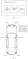
FIG. 1 is a diagram of a structure of an intelligent driving device according to an embodiment of this application; -
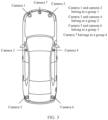
FIG. 2 is a diagram of a camera group according to an embodiment of this application; -
FIG. 3 is a diagram of another camera group according to an embodiment of this application; -
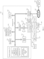
FIG. 4 is a diagram of a structure of another intelligent driving device according to an embodiment of this application; -
FIG. 5 is a diagram of a traveling control apparatus of an intelligent driving device according to an embodiment of this application; -
FIG. 6 is a diagram of location distribution of cameras on an intelligent driving device according to an embodiment of this application; -
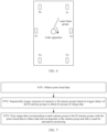
FIG. 7 is a schematic flowchart of a data fusion method according to an embodiment of this application; -
FIG. 8a is a top view of a first laser beam group and a second laser beam group according to an embodiment of this application; -
FIG. 8b is a side view of a first laser beam group and a second laser beam group according to an embodiment of this application; -
FIG. 9a is another top view of a first laser beam group and a second laser beam group according to an embodiment of this application; -
FIG. 9b is another side view of a first laser beam group and a second laser beam group according to an embodiment of this application; -
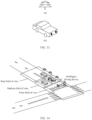
FIG. 10 is a diagram of an ambient environment according to an embodiment of this application; -
FIG. 11 is a diagram of point cloud data according to an embodiment of this application; -
FIG. 12 is a diagram of image data corresponding to a camera group according to an embodiment of this application; -
FIG. 13 is a diagram of other image data corresponding to a camera group according to an embodiment of this application; -
FIG. 14 is a diagram of a front field of view, a middle field of view, and a rear field of view according to an embodiment of this application; -
FIG. 15 is a diagram of a structure of a data fusion apparatus according to an embodiment of this application; -
FIG. 16 is a diagram of an intelligent driving device according to an embodiment of this application; and -
FIG. 17 is a diagram of a structure of another data fusion apparatus according to an embodiment of this application. - The following describes embodiments of this application with reference to the accompanying drawings in embodiments of this application.
- In this application, the term "example", "for example", or the like is used to give an example, an illustration, or a description. Any embodiment or design scheme described as an "example" or "for example" in this application should not be explained as being more preferred or having more advantages than another embodiment or design scheme. Exactly, use of the terms such as "example" or "for example" is intended to present a related concept in a specific manner.
- In embodiments of this application, "at least one" means one or more, and "a plurality of" means two or more. "At least one of the following items (pieces)" or a similar expression thereof means any combination of these items, including any combination of singular items (pieces) or plural items (pieces). For example, at least one of a, b, or c may indicate a, b, c, "a and b", "a and c", "b and c", or "a, b, and c", where a, b, and c may be singular or plural. The term "and/or" describes an association between associated objects, and indicates that three relationships may exist. For example, A and/or B may indicate the following three cases: Only A exists, both A and B exist, and only B exists, where A and B may be singular or plural. The character "/" generally indicates an "or" relationship between the associated objects.
- "First", "second", "third", "fourth", and the like mentioned in embodiments of this application are used to distinguish between different objects, but are not used to describe a particular order of the objects. In addition, the terms "including" and "having" and any other variants thereof are intended to cover a non-exclusive inclusion. For example, a process, a method, a system, a product, or a device that includes a series of steps or units is not limited to the listed steps or units, but optionally further includes an unlisted step or unit, or optionally further includes another inherent step or unit of the process, the method, the product, or the device.
- "Embodiments" mentioned herein mean that specific features, structures, or characteristics described in combination with embodiments may be included in at least one embodiment of this application. The phrase shown in various locations in the specification may not necessarily refer to a same embodiment, and is not an independent or optional embodiment exclusive from another embodiment. It is explicitly and implicitly understood by a person skilled in the art that embodiments described in the specification may be combined with another embodiment.
-
FIG. 1 is a diagram of a structure of anintelligent driving device 100 according to an embodiment of this application. Theintelligent driving device 100 includes acomputing platform 101 and M camera groups 102. M is a positive integer greater than or equal to 1. M may alternatively be a positive integer greater than or equal to 2. Thecomputing platform 101 may be carried in theintelligent driving device 100, or may not be carried in theintelligent driving device 100. For example, thecomputing platform 101 may be carried in a cloud server. This is not limited in embodiments of this application. Thecomputing platform 101 may be understood as an apparatus having a computing capability. Thecomputing platform 101 is configured to: obtain point cloud data and M groups of image data, and fuse image data corresponding to each camera group in the M groups of image data with the point cloud data, to obtain data that corresponds to a camera group and that is used for perception processing. For specific related descriptions, refer to the following embodiments. Each of the M camera groups includes at least one camera. In an example,FIG. 2 is a diagram of a camera group according to an embodiment of this application. M=3. Three camera groups are agroup 1, agroup 2, and agroup 3. Theintelligent driving device 100 includes six cameras: acamera 1, acamera 2, acamera 3, acamera 4, acamera 5, and acamera 6. Each camera group includes two cameras. Thecamera 1 and thecamera 2 belong to thegroup 1, and thecamera 1 and thecamera 2 are disposed opposite to each other at a front part of theintelligent driving device 100. Thecamera 3 and thecamera 4 belong to thegroup 2, and thecamera 3 and thecamera 4 are disposed opposite to each other on two sides of theintelligent driving device 100. Thecamera 5 and thecamera 6 belong to thegroup 3, and thecamera 5 and thecamera 6 are disposed opposite to each other at a rear part of theintelligent driving device 100. In another example,FIG. 3 is a diagram of another camera group according to an embodiment of this application. M=4. Four camera groups are agroup 1, agroup 2, agroup 3, and agroup 4. Theintelligent driving device 100 includes six cameras: acamera 1, acamera 2, acamera 3, acamera 4, acamera 5, acamera 6, and acamera 7. Each camera group includes at least one camera. Thecamera 1 and thecamera 2 belong to thegroup 1, and thecamera 1 and thecamera 2 are disposed opposite to each other at a front part of theintelligent driving device 100. Thecamera 3 and thecamera 4 belong to thegroup 2, and thecamera 3 and thecamera 4 are disposed opposite to each other on two sides of theintelligent driving device 100. Thecamera 5 and thecamera 6 belong to thegroup 3, and thecamera 5 and thecamera 6 are disposed opposite to each other at a rear part of theintelligent driving device 100. Thecamera 7 belongs to thegroup 4, and thecamera 7 faces a traveling direction of theintelligent driving device 100.FIG. 2 andFIG. 3 are used as examples to describe locations of cameras on the intelligent driving device when a quantity of cameras on the intelligent driving device is an even number or an odd number. The locations of the cameras may vary with a vehicle type of the intelligent driving device or the like. This is not limited in embodiments of this application. - The
intelligent driving device 100 may further include one or more laser emitting apparatuses 103. When theintelligent driving device 100 includes one laser emitting apparatus 103, the laser emitting apparatus 103 is configured to generate a first laser beam group and a second laser beam group. In other words, it may be understood that the first laser beam group and the second laser beam group are from a same laser emitting apparatus. When theintelligent driving device 100 includes two laser emitting apparatuses 103, for example, a first laser emitting apparatus and a second laser emitting apparatus, the first laser emitting apparatus is configured to generate a first laser beam group, and the second laser emitting apparatus is configured to generate a second laser beam group. In other words, it may be understood that the first laser beam group and the second laser beam group are from different laser emitting apparatuses. The first laser beam group performs detection in a first scanning direction to obtain first data, and the second laser beam group performs detection in a second scanning direction to obtain second data. The first data and the second data are spliced to obtain point cloud data. For details, refer to related descriptions in the following embodiments. - It may be understood that the structure of the intelligent driving device in
FIG. 1 is merely an example implementation in embodiments of this application. The intelligent driving device in embodiments of this application may further include more components as required. -
FIG. 4 further describes the structure of theintelligent driving device 100 based onFIG. 1 . Theintelligent driving device 100 may include various subsystems, for example, atravel system 202, asensor system 204, acontrol system 206, one or moreperipheral devices 208, apower supply 210, acomputer system 212, and auser interface 216. Optionally, theintelligent driving device 100 may include more or fewer subsystems, and each subsystem may include a plurality of elements. In addition, each subsystem and the elements of theintelligent driving device 100 may be interconnected in a wired or wireless manner. - The
travel system 202 may include a component that provides power for theintelligent driving device 100 to move. In an embodiment, thetravel system 202 may include anengine 218, anenergy source 219, a transmission apparatus 220, and a wheel/tire 221. Theengine 218 may be an internal combustion engine, an electric motor, an air compression engine, or an engine combination of another type, for example, a hybrid engine including a gasoline engine and an electric motor, or a hybrid engine including an internal combustion engine and an air compression engine. Theengine 218 converts theenergy source 219 into mechanical energy. - Examples of the
energy source 219 include gasoline, diesel, another oil-based fuel, propane, another compressed gas-based fuel, ethanol, a solar panel, a battery, and another power source. Theenergy source 219 may also provide energy for another system of theintelligent driving device 100. - The transmission apparatus 220 may transmit mechanical power from the
engine 218 to thewheel 221. The transmission apparatus 220 may include a gearbox, a differential, and a drive shaft. In an embodiment, the transmission apparatus 220 may further include another device, for example, a clutch. The drive shaft may include one or more shafts that may be coupled to one ormore wheels 221. - The
sensor system 204 may include several sensors that sense information about an ambient environment of theintelligent driving device 100. For example, thesensor system 204 may include a positioning system 222 (the positioning system may be a GPS system, a BeiDou system, or another positioning system), an inertial measurement unit (inertial measurement unit, IMU) 224, aradar 226, alaser rangefinder 228, and acamera 230. Thesensor system 204 may further include sensors (for example, an in-vehicle air quality monitor, a fuel gauge, and an oil temperature gauge) in an internal system of the monitoredintelligent driving device 100. Sensor data from one or more of these sensors may be used to detect an object and corresponding features (a location, a shape, a direction, a speed, and the like) of the object. Such detection and identification are key functions for safe operation of the autonomousintelligent driving device 100. - The
positioning system 222 may be configured to estimate a geographical location of theintelligent driving device 100. TheIMU 224 is configured to sense and detect, based on inertia acceleration, a location and an orientation change of theintelligent driving device 100. In an embodiment, theIMU 224 may be a combination of an accelerometer and a gyroscope. - The
radar 226 may sense, by using a radio signal, an object in the ambient environment of theintelligent driving device 100. In some embodiments, in addition to sensing an object, theradar 226 may be further configured to sense a speed and/or a moving direction of the object. In an example, theradar 226 may be the laser emitting apparatus 103 inFIG. 1 . For example, theintelligent driving device 100 includes one lidar apparatus. The lidar apparatus includes two laser beam groups: a first laser beam group and a second laser beam group. The first laser beam group includes at least one laser beam, and the second laser beam group includes at least one laser beam. The first laser beam group performs detection in a first scanning direction to obtain first data, and the second laser beam group performs detection in a second scanning direction to obtain second data. The first scanning direction is different from the second scanning direction. In other words, it may be understood that rotation directions of the first laser beam group and the second laser beam group are different. Optionally, the first scanning direction may be a clockwise direction, and the second scanning direction may be an anticlockwise direction. The first data and the second data may be understood as point cloud information. For another example, theintelligent driving device 100 includes two lidar apparatuses: alidar apparatus 1 and alidar apparatus 2. Thelidar apparatus 1 includes a laser beam group, which is a first laser beam group. Thelidar apparatus 2 includes a laser beam group, which is a second laser beam group. The first laser beam group performs detection in a first scanning direction to obtain first data. The second laser beam group performs detection in a second scanning direction to obtain second data. The first scanning direction is different from the second scanning direction. - The
laser rangefinder 228 may sense, by using a laser, an object in an environment in which theintelligent driving device 100 is located. In some embodiments, thelaser rangefinder 228 may include one or more laser sources, a laser scanner, one or more detectors, and another system component. - The
camera 230 may be configured to capture a plurality of images of the ambient environment of theintelligent driving device 100. Thecamera 230 may be a static camera or a video camera. There may be one ormore cameras 230. Thecameras 230 may be grouped into theM camera groups 102 inFIG. 1 . For example, distribution of thecameras 230 on theintelligent driving device 100 may be as shown inFIG. 2 orFIG. 3 . - The
control system 206 controls operations of theintelligent driving device 100 and components of theintelligent driving device 100. Thecontrol system 206 may include various elements, including asteering system 232, athrottle 234, abrake unit 236, a sensor fusion algorithm 238, acomputer vision system 240, aroute control system 242, and an obstacle avoidance system 244. - The
steering system 232 may operate to adjust a heading direction of theintelligent driving device 100. For example, in an embodiment, the steering unit may be a steering wheel system. - The
throttle 234 is configured to control an operation speed of theengine 218, to control a speed of theintelligent driving device 100. - The
brake unit 236 is configured to control theintelligent driving device 100 to decelerate. Thebrake unit 236 may slow down thewheel 221 through friction. In another embodiment, thebrake unit 236 may convert kinetic energy of thewheel 221 into a current. Thebrake unit 236 may alternatively reduce a rotational speed of thewheel 221 in another form, to control the speed of theintelligent driving device 100. - The
computer vision system 240 may operate to process and analyze an image captured by thecamera 230, to identify an object and/or a feature in the ambient environment of theintelligent driving device 100, and/or process and analyze data information captured by theradar 226. The object and/or the feature may include a traffic signal, a road boundary, and an obstacle. Thecomputer vision system 240 may use an object identification algorithm, a structure from motion (structure from motion, SFM) algorithm, video tracking, and another computer vision technology. In some embodiments, thecomputer vision system 240 may be configured to: draw a map for an environment, track an object, estimate a speed of an object, and the like. Optionally, thecomputer vision system 240 may be thecomputing platform 101 inFIG. 1 . - The
route control system 242 is configured to determine a traveling route of theintelligent driving device 100. In some embodiments, theroute control system 242 may determine the traveling route for theintelligent driving device 100 with reference to data from the sensor fusion algorithm 238, thepositioning system 222, and one or more predetermined maps. - The obstacle avoidance system 244 is configured to identify, evaluate, and avoid or bypass, in another manner, a potential obstacle in the environment of the
intelligent driving device 100. - Certainly, in an example, the
control system 206 may additionally or alternatively include a component other than those shown and described. Alternatively, some of the foregoing components may be removed. - The
intelligent driving device 100 interacts with an external sensor, another vehicle, another computer system, or a user by using theperipheral device 208. Theperipheral device 208 may include a wireless communication system 246, a vehicle-mountedcomputer 248, amicrophone 250, and/or aspeaker 252. - In some embodiments, the
peripheral device 208 provides a means for a user of theintelligent driving device 100 to interact with theuser interface 216. For example, the vehicle-mountedcomputer 248 may provide information for the user of theintelligent driving device 100. Theuser interface 216 may further operate the vehicle-mountedcomputer 248 to receive an input of the user. The vehicle-mountedcomputer 248 may be operated by using a touchscreen. In another case, theperipheral device 208 may provide a means for theintelligent driving device 100 to communicate with another device located in the vehicle. For example, themicrophone 250 may receive an audio (for example, a voice command or another audio input) from the user of theintelligent driving device 100. Similarly, thespeaker 252 may output an audio to the user of theintelligent driving device 100. - The wireless communication system 246 may communicate with, in a wireless manner, one or more devices directly or through a communication network. For example, the wireless communication system 246 may use 3G cellular communication such as CDMA, EVD0, or GSM/GPRS, or 4G cellular communication such as LTE, or 5G cellular communication. The wireless communication system 246 may communicate with a wireless local area network (wireless local area network, WLAN) through Wi-Fi. In some embodiments, the wireless communication system 246 may directly communicate with a device through an infrared link, Bluetooth, or ZigBee. The wireless communication system 246 may include one or more dedicated short-range communications (dedicated short-range communications, DSRC) devices. These devices may include public and/or private data communication between vehicles and/or roadside stations.
- The
power supply 210 may supply power to various components of theintelligent driving device 100. In an embodiment, thepower supply 210 may be a rechargeable lithium-ion or lead-acid battery. One or more battery packs of such a battery may be configured as a power supply for supplying power to various components of theintelligent driving device 100. In some embodiments, thepower supply 210 and theenergy source 219 may be implemented together. - Some or all functions of the
intelligent driving device 100 are controlled by thecomputer system 212. Thecomputer system 212 may include at least oneprocessor 213. Theprocessor 213 executesinstructions 215 stored in a non-transient computer-readable medium like amemory 214. Thecomputer system 212 may alternatively be a plurality of computing devices that control individual components or subsystems of theintelligent driving device 100 in a distributed manner. - The
processor 213 may be any conventional processor like a commercially available CPU. Alternatively, the processor may be an ASIC or another hardware-based processor. - In various aspects described herein, the processor may be away from the vehicle and communicate with the vehicle in a wireless manner. In other aspects, some of the processes described herein are performed by a processor disposed in the vehicle, and others are performed by a remote processor.
- In some embodiments, the
memory 214 may include the instructions 215 (for example, program logic), and theinstructions 215 may be executed by theprocessor 213 to perform various functions of theintelligent driving device 100, including the functions described above. Thememory 214 may also include additional instructions, including instructions for sending data to, receiving data from, interacting with, and/or controlling one or more of thetravel system 202, thesensor system 204, thecontrol system 206, and theperipheral device 208. - The
memory 214 may also store data in addition to theinstructions 215, for example, point cloud data, M groups of image data corresponding to M camera groups, and other information. Such information may be used by theintelligent driving device 100 and thecomputer system 212 during operation of theintelligent driving device 100 in an autonomous mode, a semi-autonomous mode, and/or a manual mode. - The
user interface 216 is configured to provide information for the user of theintelligent driving device 100 or receive information from the user. Optionally, theuser interface 216 may include one or more input/output devices within a set ofperipheral devices 208, such as the wireless communication system 246, the vehicle-mountedcomputer 248, themicrophone 250, and thespeaker 252. - The
computer system 212 may control functions of theintelligent driving device 100 based on inputs received from various subsystems (for example, thetravel system 202, thesensor system 204, and the control system 206) and theuser interface 216. For example, thecomputer system 212 may use an input from thecontrol system 206 to control thesteering system 232 to avoid an obstacle detected by thesensor system 204 and the obstacle avoidance system 244. In some embodiments, thecomputer system 212 may operate to provide control on theintelligent driving device 100 and the subsystems of theintelligent driving device 100 in many aspects. - Optionally, one or more of the foregoing components may be mounted separately from or associated with the
intelligent driving device 100. For example, thememory 214 may be partially or completely separated from theintelligent driving device 100. The foregoing components may be communicatively coupled together in a wired and/or wireless manner. - Optionally, the foregoing components are merely examples. During actual application, the components in the foregoing modules may be added or deleted according to an actual requirement.
FIG. 4 should not be understood as any limitation on embodiments of this application. - The
intelligent driving device 100 may be a car, a truck, a motorcycle, a bus, a ship, an airplane, a helicopter, a lawn mower, an entertainment vehicle, a playground vehicle, a construction device, a tram, a golf cart, a train, a cart, a smart home device, or the like. This is not particularly limited in embodiments of this application. - It may be understood that the structure of the intelligent driving device in
FIG. 4 is merely an example implementation in embodiments of this application. The intelligent driving device in embodiments of this application includes but is not limited to the structure. -
FIG. 5 is a diagram of a traveling control apparatus of an intelligent driving device according to an embodiment of this application. The traveling control apparatus is applied toFIG. 4 , and is equivalent to thecomputer system 212 shown inFIG. 4 . The traveling control apparatus may include aprocessor 213, and theprocessor 213 is coupled to a system bus 505. Theprocessor 213 may be one or more processors, and each of the processors may include one or more processor cores. Amemory 214 may store related data information, and thememory 214 is coupled to the system bus 505. A display adapter (display adapter) 507 may drive adisplay 509, and thedisplay 509 is coupled to the system bus 505. The system bus 505 is coupled to an input/output (I/O)bus 513 through abus bridge 501. An I/O interface 515 is coupled to the I/O bus 513. The I/O interface 515 communicates with a plurality of I/O devices, for example, an input device 517 (for example, a keyboard, a mouse, or a touchscreen) and a media tray (media tray) 521 (for example, a CD-ROM or a multimedia interface). A transceiver 523 (which may send and/or receive a radio communication signal) and a camera 555 (which may capture static and dynamic digital video images) are coupled to anexternal USB interface 525. Optionally, an interface connected to the I/O interface 515 may be a USB interface. - The
processor 213 may be any conventional processor, including a reduced instruction set computer (reduced instruction set computer, RISC), a complex instruction set computer (complex instruction set computer, CISC), or a combination thereof. Optionally, the processor may be an application-specific integrated circuit ASIC. Optionally, theprocessor 213 may be a neural network processor or a combination of a neural network processor and the foregoing conventional processor. - Optionally, in various embodiments described herein, the
computer system 212 may be located away from the intelligent driving device and may communicate with the intelligent driving device in a wireless manner. In other aspects, some of the processes described in this specification are performed by a processor disposed in the intelligent driving device, and others are performed by a remote processor. - The
computer system 212 may communicate with asoftware deploying server 549 through anetwork interface 529. Thenetwork interface 529 is a hardware network interface, for example, a network adapter. Anetwork 527 may be an external network like the Internet, or may be an internal network like the Ethernet or a virtual private network (virtual private network, VPN). Optionally, thenetwork 527 may alternatively be a wireless network, for example, a Wi-Fi network or a cellular network. - The transceiver 523 (which may send and/or receive a radio communication signal) may use various wireless communication manners such as but not limited to a second generation mobile communication network (2nd generation mobile network, 2G), 3G, 4G, or 5G, or may use a DSRC technology, a long term evolution-vehicle-to-everything (long term evolution-vehicle-to-everything, LTE-V2X) technology, or the like. A main function of the
transceiver 523 is to receive information data sent by an external device, and send, to the external device for storage and analysis, information data generated when the intelligent driving device travels on a target road section. - A hard
disk drive interface 531 is coupled to the system bus 505. The harddisk drive interface 531 is connected to ahard disk drive 533. Asystem memory 535 is coupled to the system bus 505. Data running in thesystem memory 535 may include anoperating system 537 and anapplication 543 of thecomputer system 212. - The
system memory 535 is coupled to the system bus 505. For example, in this application, thesystem memory 535 may be configured to store traveling information of the vehicle passing the target road section in the memory in a specific format. - The operating system (operating system, OS) 537 includes a shell (shell) 539 and a kernel (kernel) 541. The
shell 539 is an interface between a user and the kernel of the operating system. Theshell 539 is an outermost layer of the operating system. Theshell 539 manages interaction between the user and the operating system: waiting for an input of the user, explaining the input of the user to the operating system, and processing various output results of the operating system. - The
kernel 541 includes parts that are in the operating system and that are used to manage a memory, a file, a peripheral device, and a system resource. When directly interacting with hardware, the kernel of the operating system usually runs a process, provides inter-process communication, and provides functions such as CPU time slice management and interruption, memory management, and I/O management. - The
application 543 includes an autonomous driving-relatedprogram 547, for example, a program for managing interaction between an autonomous driving vehicle and an obstacle on a road, a program for controlling a route or a speed of the autonomous driving vehicle, and a program for controlling interaction between the autonomous driving vehicle and another autonomous driving vehicle on the road. Theapplication 543 also exists in a system of a deploying server (deploying server) 549. In an embodiment, when the autonomous driving-relatedprogram 547 needs to be executed, thecomputer system 212 may download the autonomous driving-relatedprogram 547 from the deployingserver 549. - A
sensor 553 is associated with thecomputer system 212. Thesensor 553 is configured to detect an ambient environment of thecomputer system 212. For example, thesensor 553 may detect an animal, a vehicle, an obstacle, a crosswalk, and the like. Further, the sensor may detect an environment around an object like the animal, the vehicle, the obstacle, and the crosswalk, for example, an environment around the animal, for example, another animal that appears around the animal, a weather condition, and brightness of the ambient environment. Optionally, if thecomputer system 212 is located in an autonomous driving vehicle, the sensor may be a camera, an infrared sensor, a chemical detector, a microphone, or the like. - It may be understood that the traveling control apparatus of an intelligent driving device in
FIG. 5 is merely an example implementation in embodiments of this application. The traveling control apparatus applied to the intelligent driving device in embodiments of this application includes but is not limited to the foregoing structure. - In a current multi-sensor fusion solution, a lidar apparatus has a fixed scan cycle, and a camera is triggered at a fixed frequency.
FIG. 6 is a diagram of location distribution of cameras on an intelligent driving device. The intelligent driving device includes one lidar apparatus and six cameras, and the six cameras are T1, T2, T3, T4, T5, and T6. The lidar apparatus is located in the middle of the intelligent driving device, and the lidar apparatus emits only one laser beam group. The laser beam group includes at least one laser beam. A scanning start location of the lidar apparatus may be a location of the camera T1, and the lidar apparatus may rotate clockwise from the location of the camera T1 to perform a round of scanning in sequence. The cameras are scanned at different time. For example, a time difference between time when the location of the camera T1 is scanned and time when a location of the camera T6 is scanned is large, and correspondingly, a time difference between corresponding point cloud data is also large. Usually, a scanning start angle with a largest such difference is placed in a direction that has a low requirement on precision, for example, a backward direction. For example, a scanning start location of the lidar apparatus may be a location of the camera T3, and the lidar apparatus may rotate clockwise from the location of the camera T3 to perform a round of scanning in sequence. However, this is only a workaround. In this manner, point cloud compensation may be performed. However, in a scenario of an oncoming vehicle, because a speed of the opposite party is inaccurately estimated, accuracy of point cloud compensation is low. However, for camera triggering, in a solution, the six cameras may be triggered at the same time. To be specific, six pieces of image data corresponding to the six cameras may be obtained at a same moment, to trigger corresponding model inference. However, this causes a performance problem due to centralized resource occupation and peak load contention. In another solution, different cameras may be triggered at different time. To be specific, camera exposure is triggered only when the lidar apparatus scans a corresponding position of a camera, to obtain corresponding image data. In this way, optimal matching between a point cloud and an image at a single angle of view can be achieved. In addition, load balancing is implemented to some extent. However, due to a time difference between triggering time of the cameras, there is a time difference between obtained image data. In a high-speed motion scenario, effective spicing and fusion cannot be performed. Therefore, in a scenario in which the lidar and the camera are fused, because a timestamp of the lidar does not match a timestamp of the camera, a fusion effect is usually poor, and consequently, the ambient environment of the vehicle cannot be accurately identified. To resolve the foregoing problem, embodiments of this application provide the following solutions. - Based on the structures of the intelligent driving device provided in
FIG. 1 andFIG. 4 and the vehicle traveling control apparatus that is applied to the intelligent driving device and that is provided inFIG. 5 , this application provides a data fusion method. -
FIG. 7 is a schematic flowchart of a data fusion method according to an embodiment of this application. The method may be applied to the intelligent driving device inFIG. 1 . The computing platform in the intelligent driving device may be configured to support and perform step S701 to step S703 in a method procedure shown inFIG. 7 . The method may be applied to an intelligent driving scenario. Intelligent driving includes intelligent assisted driving, autonomous driving, self-driving, and the like. This is not limited in embodiments of this application. The method may include the following step S701 to step S703. - S701: Obtain point cloud data.
- The point cloud data is obtained through detection in a first scanning direction and a second scanning direction respectively based on a first laser beam group and a second laser beam group. Specifically, the obtaining point cloud data may include: obtaining first data and second data, where the first data is obtained through detection by the first laser beam group in the first scanning direction, and the second data is obtained through detection by the second laser beam group in the second scanning direction; and then splicing the first data and the second data to obtain the point cloud data.
- In an implementation, the first laser beam group and the second laser beam group are from a same laser emitting apparatus, and the laser emitting apparatus may be referred to as a bidirectional lidar apparatus. In another implementation, the first laser beam group is from a first laser beam emitting apparatus, and the second laser beam group is from a second laser beam emitting apparatus. In other words, it may be understood that the first laser beam group and the second laser beam group are from different laser emitting apparatuses, and the first laser beam emitting apparatus and the second laser beam emitting apparatus may be lidar apparatuses. The first laser beam group includes at least one laser beam, and the second laser beam group includes at least one laser beam. In an example, when the first laser beam group and the second laser beam group are from a same laser emitting apparatus, a top view of the first laser beam group and the second laser beam group is shown in
FIG. 8a , and a side view of the first laser beam group and the second laser beam group is shown inFIG. 8b . In another example, when the first laser beam group and the second laser beam group are from different laser emitting apparatuses, a top view of the first laser beam group and the second laser beam group is shown inFIG. 9a , and a side view of the first laser beam group and the second laser beam group is shown inFIG. 9b . - That the first scanning direction is different from the second scanning direction may be understood as that rotation directions of the first laser beam group and the second laser beam group are different. For example, the first scanning direction is a clockwise direction, and the second scanning direction is an anticlockwise direction. For another example, the first scanning direction is an anticlockwise direction, and the second scanning direction is a clockwise direction.
- The point cloud data may be partial environment point cloud data, but not complete environment point cloud data. The first data is data obtained through scanning in a specific sector range by the first laser beam group in the first scanning direction, and the second data is data obtained through scanning in a specific sector range by the second laser beam group in the second scanning direction. Optionally, scan cycles of the first laser beam group and the second laser beam group are the same. In other words, it may be understood that scanning speeds of the first laser beam group and the second laser beam group are the same. Optionally, scanning start locations of the first laser beam group and the second laser beam group may be adjusted. The splicing the first data and the second data may be understood as rotating and translating the first data and the second data to a unified coordinate system, so that the first data and the second data can form partial environment point cloud data, that is, may be understood as a process of registering overlapping parts of the first data and the second data. Splicing may be understood as point cloud splicing, integration, or the like. This is not limited in embodiments of this application. In an example,
FIG. 10 is a diagram of an ambient environment according to an embodiment of this application. Herein, (a) inFIG. 11 is a diagram of first data obtained through detection by a first laser beam group in a first scanning direction, where a traveling direction of an intelligent driving device is used as a reference, and the first scanning direction is an anticlockwise direction; (b) inFIG. 11 is a diagram of second data obtained through detection by a second laser beam group in a second scanning direction, where the traveling direction of the intelligent driving device is used as a reference, and the second scanning direction is a clockwise direction; and (c) inFIG. 11 is a diagram of point cloud data obtained by splicing the first data and the second data. - S702: Sequentially trigger exposure of cameras in M camera groups based on trigger delays of the M camera groups to obtain M groups of image data.
- Cameras in a same camera group are exposed simultaneously. For example, if a camera group includes a
camera 1 and acamera 2, thecamera 1 and thecamera 2 are exposed simultaneously. A quantity of pieces of image data in each of the M groups of image data is the same as a quantity of cameras in each group. For example, one camera group includes acamera 1 and acamera 2. Correspondingly, there are two pieces of image data of the camera group. In other words, the two pieces of image data are one group of image data, namely, image data corresponding to the camera group. M is a positive integer greater than or equal to 1. M may alternatively be a positive integer greater than or equal to 2. - The trigger delay is related to the scan cycles of the first laser beam group and the second laser beam group, and the scan cycle may be understood as a scanning speed. The trigger delay is obtained in the following manner: determining a location of each camera group in the M camera groups, and determining a trigger delay of each camera group based on the scan cycle and the location of each camera group in the M camera groups. A location of each camera in the M camera groups may be a spatial location at which the camera is distributed. For example, the camera may be distributed at a front part, on either side, or at a rear part of the intelligent driving device. The trigger delay of each camera group is determined based on the scan cycle and the location of each camera group in the M camera groups, as shown in Formula (1), and is specifically as follows:

- Herein, Δ i,j is a trigger delay of an ith camera (i ∈ (0, M]) during scanning of a jth laser beam group (j ∈ (0,2]), θi,j is an offset angle between the ith camera and a scanning start angle of the jth laser beam group from which the jth laser beam group rotates and performs scanning in a scanning direction of the jth laser beam group, and φj is a scanning angular velocity of the jth laser beam group.
- Optionally, the M camera groups include a front-part group, a side-part group, and a rear-part group. The front-part group includes a first camera and a second camera, and the first camera and the second camera are disposed opposite to each other at the front part of the intelligent driving device. The side-part group includes a third camera and a fourth camera, and the third camera and the fourth camera are disposed opposite to each other on two sides of the intelligent driving device. The rear-part group includes a fifth camera and a sixth camera, and the fifth camera and the sixth camera are disposed opposite to each other at the rear part of the intelligent driving device. In an example, M=3. Three camera groups are a
group 1, agroup 2, and agroup 3. The intelligent driving device includes six cameras: acamera 1, acamera 2, acamera 3, acamera 4, acamera 5, and acamera 6. Each camera group includes two cameras. For specific related descriptions, refer toFIG. 2 . Optionally, the M camera groups may further include a forward group. The forward group includes a seventh camera, and the seventh camera faces the traveling direction of the intelligent driving device. In an example, M=4. Four camera groups are agroup 1, agroup 2, agroup 3, and agroup 4. Theintelligent driving device 100 includes six cameras: acamera 1, acamera 2, acamera 3, acamera 4, acamera 5, acamera 6, and acamera 7. Each camera group includes at least one camera. For details, refer toFIG. 3 . - The M camera groups include a first camera group and a second camera group. A trigger delay of the first camera group is a first delay, and a trigger delay of the second camera group is a second delay. The sequentially triggering exposure of cameras in M camera groups based on trigger delays of the M camera groups to obtain M groups of image data includes: starting a first timer to set an initial moment; when an interval between an indicated moment of the first timer and the initial moment is the first delay, triggering exposure of a camera in the first camera group to obtain image data corresponding to the first camera group; and when an interval between an indicated moment of the first timer and the initial moment is the second delay, triggering exposure of a camera in the second camera group to obtain image data corresponding to the second camera group.
- The first delay may be 0, or may be another value. When the first delay is 0, it may be understood that exposure of the camera in the first camera group is triggered when the first timer is started, to obtain the image data corresponding to the first camera group. Optionally, the first laser beam group and the second laser beam group may perform detection respectively in the first scanning direction and the second scanning direction at the initial moment. Certainly, alternatively, the first laser beam group and the second laser beam group may perform detection respectively in the first scanning direction and the second scanning direction before or after the initial moment. This is not limited in embodiments of this application. Optionally, the second delay may be greater than the first delay.
- The image data corresponding to the first camera group may be image data captured by all the cameras in the first camera group. For example, if the first camera group includes a
camera 1 and acamera 2, the image data corresponding to the first camera group may be image data obtained by thecamera 1 through exposure and image data obtained by thecamera 2 through exposure. The same applies to the image data corresponding to the second camera group. - There may be one or more first timers. When there are a plurality of first timers, a quantity of first timers is the same as a quantity of cameras in a camera group. For example, if there are two cameras in the first camera group: a
camera 1 and acamera 2, there are two first timers: atimer 1 and atimer 2. Thetimer 1 and thetimer 2 may be synchronous. For example, the first delay is 0. Thetimer 1 and thetimer 2 are started to trigger exposure of thecamera 1 and thecamera 2 in the first camera group to obtain the image data corresponding to the first camera group. To be specific, thetimer 1 triggers exposure of thecamera 1 to obtain the image data corresponding to thecamera 1, and thetimer 2 triggers exposure of thecamera 2 to obtain the image data corresponding to thecamera 2. - In an example, the first delay is 0 milliseconds (ms), and the second delay is 30 ms. The first camera group includes a
camera 1 and acamera 2, and the second camera group includes acamera 3 and acamera 4. The first timer is started to set the initial moment to t0. When the indicated moment of the first timer is t0 and the first delay between the indicated moment t0 and the initial moment t0 is 0 ms, exposure of thecamera 1 and thecamera 2 is triggered to obtain image data captured by thecamera 1 and image data captured by thecamera 2. For the environment inFIG. 10 , as shown inFIG. 12, (a) in FIG. 12 is the image data captured by thecamera 1, namely, image data in a front field of view in the traveling direction of the intelligent driving device, and (b) inFIG. 12 is the image data captured by thecamera 2, namely, image data in the front field of view in the traveling direction of the intelligent driving device. When the indicated moment of the first timer is t1, and the second delay between the indicated moment t1 and the initial moment t0 is 30 ms, exposure of thecamera 3 and thecamera 4 is triggered to obtain image data captured by thecamera 3 and image data captured by thecamera 4. For the environment inFIG. 10 , as shown inFIG. 13, (a) in FIG. 13 is the image data captured by thecamera 3, namely, image data in a middle field of view in the traveling direction of the intelligent driving device, and (b) inFIG. 13 is the image data captured by thecamera 4, namely, image data in the middle field of view in the traveling direction of the intelligent driving device. - S703: Fuse image data corresponding to each camera group in the M camera groups with the point cloud data to obtain data that corresponds to the camera group and that is used for perception processing.
- Fusing the image data corresponding to each camera group in the M camera groups with the point cloud data to obtain the data that corresponds to the camera group and that is used for perception processing may be as follows: using the image data corresponding to each camera group in the M camera groups and the point cloud data as input data, and inputting the input data to a fusion perception algorithm, for example, a multi-modal fusion algorithm, to obtain the data that corresponds to the camera group and that is used for perception processing.
- For example, (c) in
FIG. 11 is a diagram of the point cloud data obtained by splicing the first data and the second data based on the environment inFIG. 10 . As shown inFIG. 12, (a) in FIG. 12 is the image data captured by thecamera 1 in the first camera group, and (b) inFIG. 12 is the image data captured by thecamera 2 in the first camera group. Correspondingly, the point cloud data in (c) inFIG. 11 may be fused with the image data captured by thecamera 1 in the first camera group in (a) inFIG. 12 and the image data captured by thecamera 2 in the first camera group in (b) inFIG. 12 , to obtain the data that corresponds to the camera group and that is used for perception processing, that is, obtain a fusion result of the point cloud data and the image data in the front field of view in the traveling direction of the intelligent driving device. Further,FIG. 14 is a diagram of a front field of view, a middle field of view, and a rear field of view of the intelligent driving device in the environment shown inFIG. 10 . Correspondingly, a process is similar to a process of obtaining the fusion result of the point cloud data and the image data in the front field of view, and a fusion result of point cloud data and image data in the middle field of view in the traveling direction of the intelligent driving device and a fusion result of point cloud data and image data in the rear field of view in the traveling direction of the intelligent driving device may be obtained. - In a possible implementation, the image data corresponding to each of the M camera groups may be fused. In other words, it may be understood that image data corresponding to at least two of the M camera groups may be used as input data, and the input data is input to a camera perception algorithm, for example, an image 2D target detection algorithm, to obtain a corresponding result. For example, M=3, and three camera groups are a
camera group 1, acamera group 2, and acamera group 3. Each camera group includes two cameras. For example, thecamera group 1 includes acamera 1 and acamera 2, thecamera group 2 includes acamera 3 and acamera 4, and thecamera group 3 includes acamera 5 and acamera 6. For example, image data of thecamera 1 in thecamera group 1, image data of thecamera 2 in thecamera group 1, image data of thecamera 3 in thecamera group 2, and image data of thecamera 4 in thecamera group 2 may be input to the camera perception algorithm, to obtain a corresponding result. For example, the result may be used to detect a target obstacle. - In the foregoing method, the traveling direction of the intelligent driving device is used as a reference. In this application, the point cloud data may be fused with the image data of the camera group corresponding to the front field of view of the intelligent driving device, to improve a fusion effect of the point cloud data and the image data in the front field of view. Similarly, a fusion effect of the point cloud data and the image data in the middle field of view and a fusion effect of the point cloud data and the image data in the rear field of view may also be improved. In this way, the ambient environment of the vehicle is more accurately identified. This is more conducive to planning and implementation of an autonomous driving task.
- The foregoing describes in detail methods in embodiments of this application. The following provides apparatuses in embodiments of this application.
-
FIG. 15 is a diagram of a structure of a data fusion apparatus 1500 according to an embodiment of this application. The data fusion apparatus 1500 is a vehicle-mounted computing platform or a cloud server. The data fusion apparatus 1500 includes acommunication unit 1501 and aprocessing unit 1502. The apparatus 1500 may be implemented by using hardware, software, or a combination of software and hardware. - The
processing unit 1502 is configured to obtain point cloud data. The point cloud data is obtained through detection in a first scanning direction and a second scanning direction respectively based on a first laser beam group and a second laser beam group, and the first scanning direction is different from the second scanning direction. - The
processing unit 1502 is configured to sequentially trigger exposure of cameras in M camera groups based on trigger delays of the M camera groups to obtain M groups of image data. Cameras in a same camera group are exposed simultaneously. The trigger delay is related to a scan cycle of the first laser beam group and the second laser beam group, and M is a positive integer greater than or equal to 1. - The
processing unit 1502 is configured to fuse image data corresponding to each camera group in the M camera groups with the point cloud data to obtain data that corresponds to the camera group and that is used for perception processing. - In a possible implementation, the
processing unit 1502 is configured to obtain first data. The first data is obtained through detection by the first laser beam group in the first scanning direction. Theprocessing unit 1502 is configured to obtain second data. The second data is obtained through detection by the second laser beam group in the second scanning direction. Theprocessing unit 1502 is configured to splice the first data and the second data to obtain the point cloud data. - In another possible implementation, the first laser beam group and the second laser beam group are from a same laser emitting apparatus.
- In still another possible implementation, the first laser beam group is from a first laser emitting apparatus, and the second laser beam group is from a second laser emitting apparatus.
- In still another possible implementation, the
processing unit 1502 is configured to: determine a location of each camera group in the M camera groups, and determine a trigger delay of each camera group based on the scan cycle and the location of each camera group in the M camera groups. - In still another possible implementation, the M camera groups include a first camera group and a second camera group, a trigger delay of the first camera group is a first delay, and a trigger delay of the second camera group is a second delay. The
processing unit 1502 is configured to start a first timer to set an initial moment. Theprocessing unit 1502 is configured to: when an interval between an indicated moment of the first timer and the initial moment is the first delay, trigger exposure of a camera in the first camera group to obtain image data corresponding to the first camera group. Theprocessing unit 1502 is configured to: when an interval between an indicated moment of the first timer and the initial moment is the second delay, trigger exposure of a camera in the second camera group to obtain image data corresponding to the second camera group. - In still another possible implementation, the M camera groups include a front-part group, a side-part group, and a rear-part group. The front-part group includes a first camera and a second camera, and the first camera and the second camera are disposed opposite to each other at the front part of the intelligent driving device. The side-part group includes a third camera and a fourth camera, and the third camera and the fourth camera are disposed opposite to each other on two sides of the intelligent driving device. The rear-part group includes a fifth camera and a sixth camera, and the fifth camera and the sixth camera are disposed opposite to each other at the rear part of the intelligent driving device.
- In still another possible implementation, the M camera groups further include a forward group, the forward group includes a seventh camera, and the seventh camera faces the traveling direction of the intelligent driving device.
- For implementations and beneficial effects of the modules, refer to corresponding descriptions in the method embodiment shown in
FIG. 7 . -
FIG. 16 is a diagram of anintelligent driving device 1600 according to an embodiment of this application. Theintelligent driving device 1600 includes acomputing platform 1601 andM camera groups 1602. Thecomputing platform 1601 is configured to: - obtain point cloud data, where the point cloud data is obtained through detection in a first scanning direction and a second scanning direction respectively based on a first laser beam group and a second laser beam group, and the first scanning direction is different from the second scanning direction;
- sequentially trigger exposure of cameras in the M camera groups based on trigger delays of the M camera groups to obtain M groups of image data, where cameras in a same camera group are exposed simultaneously, the trigger delay is related to a scan cycle of the first laser beam group and the second laser beam group, and M is a positive integer greater than or equal to 1; and
- fuse image data corresponding to each camera group in the M camera groups with the point cloud data to obtain data that corresponds to the camera group and that is used for perception processing.
- In a possible implementation, when obtaining the point cloud data, the
computing platform 1601 is configured to: obtain first data, where the first data is obtained through detection by the first laser beam group in the first scanning direction; obtain second data, where the second data is obtained through detection by the second laser beam group in the second scanning direction; and splice the first data and the second data to obtain the point cloud data. - In another possible implementation, the first laser beam group and the second laser beam group are from a same laser emitting apparatus.
- In still another possible implementation, the first laser beam group is from a first laser emitting apparatus, and the second laser beam group is from a second laser emitting apparatus.
- In still another possible implementation, the first laser emitting apparatus and the second laser emitting apparatus are lidar apparatuses.
- In still another possible implementation, the
computing platform 1601 is configured to: determine a location of each camera group in the M camera groups, and determine a trigger delay of each camera group based on the scan cycle and the location of each camera group in the M camera groups. - In still another possible implementation, the M camera groups include a first camera group and a second camera group. A trigger delay of the first camera group is a first delay. A trigger delay of the second camera group is a second delay. The
computing platform 1601 is further configured to: start a first timer to set an initial moment; when an interval between an indicated moment of the first timer and the initial moment is the first delay, trigger exposure of a camera in the first camera group to obtain image data corresponding to the first camera group; and when an interval between the indicated moment of the first timer and the initial moment is the second delay, trigger exposure of a camera in the second camera group to obtain image data corresponding to the second camera group. - In still another possible implementation, the M camera groups include a front-part group, a side-part group, and a rear-part group. The front-part group includes a first camera and a second camera, and the first camera and the second camera are disposed opposite to each other at the front part of the intelligent driving device. The side-part group includes a third camera and a fourth camera, and the third camera and the fourth camera are disposed opposite to each other on two sides of the intelligent driving device. The rear-part group includes a fifth camera and a sixth camera, and the fifth camera and the sixth camera are disposed opposite to each other at the rear part of the intelligent driving device.
- In still another possible implementation, the M camera groups further include a forward group, the forward group includes a seventh camera, and the seventh camera faces the traveling direction of the intelligent driving device.
- For implementations and beneficial effects of the modules, refer to corresponding descriptions in the method embodiment shown in
FIG. 7 . -
FIG. 17 is a diagram of a data fusion apparatus 1700 according to an embodiment of this application. The data fusion apparatus 1700 may be a vehicle-mounted computing platform or a cloud server. The data fusion apparatus 1700 includes at least oneprocessor 1701 and acommunication interface 1703, and optionally, further includes amemory 1702. Theprocessor 1701, thememory 1702, and thecommunication interface 1703 are connected to each other through a bus 1704. Optionally, the data fusion apparatus 1700 may be a vehicle-mounted computing platform or a cloud server. - The
memory 1702 includes but is not limited to a random-access memory (random-access memory, RAM), a read-only memory (read-only memory, ROM), an erasable programmable read-only memory (erasable programmable read-only memory, EPROM), or a compact disc read-only memory (compact disc read-only memory, CD-ROM). Thememory 1702 is configured to store a related computer program and data. Thecommunication interface 1703 is configured to receive and send data. - The
processor 1701 may be one or more central processing units (central processing units, CPUs). When theprocessor 1701 is one CPU, the CPU may be a single-core CPU or a multi-core CPU. - The
processor 1701 in the data fusion apparatus 1700 is configured to read computer program code stored in thememory 1702, to perform the following operations: - obtain point cloud data, where the point cloud data is obtained through detection in a first scanning direction and a second scanning direction respectively based on a first laser beam group and a second laser beam group, and the first scanning direction is different from the second scanning direction;
- sequentially trigger exposure of cameras in M camera groups based on trigger delays of the M camera groups to obtain M groups of image data, where cameras in a same camera group are exposed simultaneously, the trigger delay is related to a scan cycle of the first laser beam group and the second laser beam group, and M is a positive integer greater than or equal to 1; and
- fuse image data corresponding to each camera group in the M camera groups with the point cloud data to obtain data that corresponds to the camera group and that is used for perception processing.
- In a possible implementation, the
processor 1701 is configured to obtain first data. The first data is obtained through detection by the first laser beam group in the first scanning direction. Theprocessor 1701 is configured to obtain second data. The second data is obtained through detection by the second laser beam group in the second scanning direction. Theprocessor 1701 is configured to splice the first data and the second data to obtain the point cloud data. - In another possible implementation, the first laser beam group and the second laser beam group are from a same laser emitting apparatus.
- In still another possible implementation, the first laser beam group is from a first laser emitting apparatus, and the second laser beam group is from a second laser emitting apparatus.
- In still another possible implementation, the
processor 1701 is configured to: determine a location of each camera group in the M camera groups, and determine a trigger delay of each camera group based on the scan cycle and the location of each camera group in the M camera groups. - In still another possible implementation, the M camera groups include a first camera group and a second camera group, a trigger delay of the first camera group is a first delay, and a trigger delay of the second camera group is a second delay. The
processor 1701 is configured to start a first timer to set an initial moment. Theprocessor 1701 is configured to: when an interval between an indicated moment of the first timer and the initial moment is the first delay, trigger exposure of a camera in the first camera group to obtain image data corresponding to the first camera group. Theprocessor 1701 is configured to: when an interval between an indicated moment of the first timer and the initial moment is the second delay, trigger exposure of a camera in the second camera group to obtain image data corresponding to the second camera group. - In still another possible implementation, the M camera groups include a front-part group, a side-part group, and a rear-part group. The front-part group includes a first camera and a second camera, and the first camera and the second camera are disposed opposite to each other at the front part of the intelligent driving device. The side-part group includes a third camera and a fourth camera, and the third camera and the fourth camera are disposed opposite to each other on two sides of the intelligent driving device. The rear-part group includes a fifth camera and a sixth camera, and the fifth camera and the sixth camera are disposed opposite to each other at the rear part of the intelligent driving device.
- In still another possible implementation, the M camera groups further include a forward group, the forward group includes a seventh camera, and the seventh camera faces the traveling direction of the intelligent driving device.
- For implementations and beneficial effects of the operations, refer to corresponding descriptions in the method embodiment shown in
FIG. 7 . - It may be understood that, the processor in embodiments of this application may be a central processing unit (central processing unit, CPU), or may be another general-purpose processor, a digital signal processor (digital signal processor, DSP), an application-specific integrated circuit (application-specific integrated circuit, ASIC), a field programmable gate array (field programmable gate array, FPGA) or another programmable logic device, a transistor logic device, a hardware component, or any combination thereof. The general-purpose processor may be a microprocessor, or may be any conventional processor.
- All or some of the foregoing embodiments may be implemented by using software, hardware, firmware, or any combination thereof. When software is used to implement the embodiments, all or some of the embodiments may be implemented in a form of computer program product. The computer program product includes one or more computer programs or instructions. When the computer programs or the instructions are loaded and executed on a computer, the procedures or functions in embodiments of this application are all or partially executed. The computer may be a general-purpose computer, a dedicated computer, a computer network, a network device, user equipment, or another programmable apparatus. The computer program or instructions may be stored in a computer-readable storage medium, or may be transmitted from a computer-readable storage medium to another computer-readable storage medium. For example, the computer program or instructions may be transmitted from a website, computer, server, or data center to another website, computer, server, or data center in a wired or wireless manner. The computer-readable storage medium may be any usable medium that can be accessed by the computer, or a data storage device, for example, a server or a data center, integrating one or more usable media. The usable medium may be a magnetic medium, for example, a floppy disk, a hard disk drive, or a magnetic tape; or may be an optical medium, for example, a digital video disc; or may be a semiconductor medium, for example, a solid-state drive. The computer-readable storage medium may be a volatile or non-volatile storage medium, or may include two types of storage media: a volatile storage medium and a non-volatile storage medium.
- In various embodiments of this application, unless otherwise stated or there is a logic conflict, terms and/or descriptions in different embodiments are consistent and may be mutually referenced, and technical features in different embodiments may be combined based on an internal logical relationship thereof, to form a new embodiment.
Claims (19)
- A data fusion method, applied to an intelligent driving scenario, wherein the method comprises:obtaining point cloud data, wherein the point cloud data is obtained through detection in a first scanning direction and a second scanning direction respectively based on a first laser beam group and a second laser beam group, and the first scanning direction is different from the second scanning direction;sequentially triggering exposure of cameras in M camera groups based on trigger delays of the M camera groups to obtain M groups of image data, wherein cameras in a same camera group are exposed simultaneously, the trigger delay is related to a scan cycle of the first laser beam group and the second laser beam group, and M is a positive integer greater than or equal to 1; andfusing image data corresponding to each camera group in the M camera groups with the point cloud data to obtain data that corresponds to the camera group and that is used for perception processing.
- The method according to claim 1, wherein the obtaining point cloud data comprises:obtaining first data, wherein the first data is obtained through detection by the first laser beam group in the first scanning direction;obtaining second data, wherein the second data is obtained through detection by the second laser beam group in the second scanning direction; andsplicing the first data and the second data to obtain the point cloud data.
- The method according to claim 1 or 2, wherein the first laser beam group and the second laser beam group are from a same laser emitting apparatus.
- The method according to claim 1 or 2, wherein the first laser beam group is from a first laser emitting apparatus, and the second laser beam group is from a second laser emitting apparatus.
- The method according to any one of claims 1 to 4, wherein the method further comprises:determining a location of each camera group in the M camera groups; anddetermining a trigger delay of each camera group in the camera groups based on the scan cycle and the location of each camera group in the M camera groups.
- The method according to any one of claims 1 to 5, wherein the M camera groups comprise a first camera group and a second camera group, a trigger delay of the first camera group is a first delay, and a trigger delay of the second camera group is a second delay; and
the sequentially triggering exposure of cameras in M camera groups based on trigger delays of the M camera groups to obtain M groups of image data comprises:starting a first timer to set an initial moment;when an interval between an indicated moment of the first timer and the initial moment is the first delay, triggering exposure of a camera in the first camera group to obtain image data corresponding to the first camera group; andwhen an interval between an indicated moment of the first timer and the initial moment is the second delay, triggering exposure of a camera in the second camera group to obtain image data corresponding to the second camera group. - The method according to any one of claims 1 to 6, wherein the M camera groups comprise a front-part group, a side-part group, and a rear-part group;the front-part group comprises a first camera and a second camera, and the first camera and the second camera are disposed opposite to each other at a front part of an intelligent driving device;the side-part group comprises a third camera and a fourth camera, and the third camera and the fourth camera are disposed opposite to each other on two sides of the intelligent driving device; andthe rear-part group comprises a fifth camera and a sixth camera, and the fifth camera and the sixth camera are disposed opposite to each other at a rear part of the intelligent driving device.
- The method according to claim 7, wherein the M camera groups further comprise a forward group, the forward group comprises a seventh camera, and the seventh camera faces a traveling direction of the intelligent driving device.
- An intelligent driving device, comprising a computing platform and M camera groups, wherein the computing platform is configured to:obtain point cloud data, wherein the point cloud data is obtained through detection in a first scanning direction and a second scanning direction respectively based on a first laser beam group and a second laser beam group, and the first scanning direction is different from the second scanning direction;sequentially trigger exposure of cameras in the M camera groups based on trigger delays of the M camera groups to obtain M groups of image data, wherein cameras in a same camera group are exposed simultaneously, the trigger delay is related to a scan cycle of the first laser beam group and the second laser beam group, and M is a positive integer greater than or equal to 1; andfuse image data corresponding to each camera group in the M camera groups with the point cloud data to obtain data that corresponds to the camera group and that is used for perception processing.
- The intelligent driving device according to claim 9, wherein when obtaining the point cloud data, the computing platform is configured to:obtain first data, wherein the first data is obtained through detection by the first laser beam group in the first scanning direction;obtain second data, wherein the second data is obtained through detection by the second laser beam group in the second scanning direction; andsplice the first data and the second data to obtain the point cloud data.
- The intelligent driving device according to claim 9 or 10, wherein the first laser beam group and the second laser beam group are from a same laser emitting apparatus.
- The intelligent driving device according to claim 9 or 10, wherein the intelligent driving device further comprises a first laser emitting apparatus and a second laser emitting apparatus; and
the first laser beam group is from the first laser emitting apparatus, and the second laser beam group is from the second laser emitting apparatus. - The intelligent driving device according to claim 12, wherein the first laser emitting apparatus and the second laser emitting apparatus are lidar apparatuses.
- The intelligent driving device according to any one of claims 9 to 13, wherein the computing platform is further configured to:determine a location of each camera group in the M camera groups; anddetermine a trigger delay of each camera group in the camera groups based on the scan cycle and the location of each camera group in the M camera groups.
- The intelligent driving device according to any one of claims 9 to 14, wherein the M camera groups comprise a first camera group and a second camera group, a trigger delay of the first camera group is a first delay, a trigger delay of the second camera group is a second delay, and the computing platform is further configured to:start a first timer to set an initial moment;when an interval between an indicated moment of the first timer and the initial moment is the first delay, trigger exposure of a camera in the first camera group to obtain image data corresponding to the first camera group; andwhen an interval between an indicated moment of the first timer and the initial moment is the second delay, trigger exposure of a camera in the second camera group to obtain image data corresponding to the second camera group.
- The intelligent driving device according to any one of claims 9 to 15, wherein the M camera groups comprise a front-part group, a side-part group, and a rear-part group;the front-part group comprises a first camera and a second camera, and the first camera and the second camera are disposed opposite to each other at a front part of the intelligent driving device;the side-part group comprises a third camera and a fourth camera, and the third camera and the fourth camera are disposed opposite to each other on two sides of the intelligent driving device; andthe rear-part group comprises a fifth camera and a sixth camera, and the fifth camera and the sixth camera are disposed opposite to each other at a rear part of the intelligent driving device.
- The intelligent driving device according to claim 16, wherein the M camera groups further comprise a forward group, the forward group comprises a seventh camera, and the seventh camera faces a traveling direction of the intelligent driving device.
- A data fusion apparatus, comprising a processor and a memory, wherein the memory and the processor are interconnected through a line, the processor is configured to obtain a computer program stored in the memory, and when the computer program is executed by the processor, the data fusion apparatus is configured to implement the method according to any one of claims 1 to 8.
- The data fusion apparatus according to claim 18, wherein the data fusion apparatus is a vehicle-mounted computing platform or a cloud server.
Applications Claiming Priority (1)
| Application Number | Priority Date | Filing Date | Title |
|---|---|---|---|
| PCT/CN2022/119125 WO2024055252A1 (en) | 2022-09-15 | 2022-09-15 | Data fusion method and apparatus, and intelligent driving device |
Publications (2)
| Publication Number | Publication Date |
|---|---|
| EP4580247A1 true EP4580247A1 (en) | 2025-07-02 |
| EP4580247A4 EP4580247A4 (en) | 2025-09-10 |
Family
ID=90273939
Family Applications (1)
| Application Number | Title | Priority Date | Filing Date |
|---|---|---|---|
| EP22958444.6A Pending EP4580247A4 (en) | 2022-09-15 | 2022-09-15 | DATA FUSION METHOD AND DEVICE AND INTELLIGENT DRIVE DEVICE |
Country Status (3)
| Country | Link |
|---|---|
| EP (1) | EP4580247A4 (en) |
| CN (1) | CN119895937A (en) |
| WO (1) | WO2024055252A1 (en) |
Families Citing this family (2)
| Publication number | Priority date | Publication date | Assignee | Title |
|---|---|---|---|---|
| CN120714874B (en) * | 2025-08-14 | 2025-12-26 | 山河智能装备股份有限公司 | Baking temperature adjusting method, system, equipment and medium for coating production line |
| CN121255027A (en) * | 2025-12-02 | 2026-01-02 | 西安星讯智能通信科技有限公司 | Interaction method and system based on multi-mode data |
Family Cites Families (13)
| Publication number | Priority date | Publication date | Assignee | Title |
|---|---|---|---|---|
| DE202013104715U1 (en) * | 2013-10-21 | 2015-01-22 | Sick Ag | Sensor with scanning unit movable about the axis of rotation |
| US10328934B2 (en) * | 2017-03-20 | 2019-06-25 | GM Global Technology Operations LLC | Temporal data associations for operating autonomous vehicles |
| US10447973B2 (en) * | 2017-08-08 | 2019-10-15 | Waymo Llc | Rotating LIDAR with co-aligned imager |
| US10523880B2 (en) * | 2017-09-28 | 2019-12-31 | Waymo Llc | Synchronized spinning LIDAR and rolling shutter camera system |
| CN108957478B (en) * | 2018-07-23 | 2021-03-26 | 上海禾赛科技股份有限公司 | Multi-sensor synchronous sampling system, control method thereof and vehicle |
| US10582137B1 (en) * | 2018-09-26 | 2020-03-03 | Zoox, Inc. | Multi-sensor data capture synchronizaiton |
| CN109858512B (en) * | 2018-12-10 | 2021-08-03 | 北京百度网讯科技有限公司 | Method, device, equipment, vehicle and storage medium for processing point cloud data |
| CN112291024B (en) * | 2019-07-25 | 2023-11-03 | 北京地平线机器人技术研发有限公司 | Information synchronization method, information synchronization device and electronic equipment |
| KR102790975B1 (en) * | 2019-12-05 | 2025-04-08 | 엘지전자 주식회사 | Method and System for Generating 3D Image |
| CN113138393B (en) * | 2020-01-17 | 2024-05-31 | 浙江菜鸟供应链管理有限公司 | Environment sensing system, control device and environment sensing data fusion device |
| CN111522026B (en) * | 2020-04-21 | 2022-12-09 | 北京三快在线科技有限公司 | A method and device for data fusion |
| CN114035201B (en) * | 2021-09-23 | 2024-12-24 | 阿里巴巴达摩院(杭州)科技有限公司 | Multi-sensor synchronization method, device and vehicle-mounted control system |
| CN216490775U (en) * | 2021-12-30 | 2022-05-10 | 北京航迹科技有限公司 | An image processing device and an unmanned vehicle |
-
2022
- 2022-09-15 CN CN202280099929.7A patent/CN119895937A/en active Pending
- 2022-09-15 EP EP22958444.6A patent/EP4580247A4/en active Pending
- 2022-09-15 WO PCT/CN2022/119125 patent/WO2024055252A1/en not_active Ceased
Also Published As
| Publication number | Publication date |
|---|---|
| WO2024055252A1 (en) | 2024-03-21 |
| EP4580247A4 (en) | 2025-09-10 |
| CN119895937A (en) | 2025-04-25 |
Similar Documents
| Publication | Publication Date | Title |
|---|---|---|
| US12061088B2 (en) | Obstacle avoidance method and apparatus | |
| US12499627B2 (en) | Data presentation method and terminal device | |
| EP4167126A1 (en) | Method for inferring lane, and method and apparatus for training lane inference model | |
| EP4307251B1 (en) | Mapping method, vehicle, computer readable storage medium, and chip | |
| WO2021159397A1 (en) | Vehicle travelable region detection method and detection device | |
| CN115042821B (en) | Vehicle control method, device, vehicle and storage medium | |
| US20250346222A1 (en) | Automatic Parking Method and Apparatus | |
| CN115330923B (en) | Point cloud data rendering method and device, vehicle, readable storage medium and chip | |
| WO2024055252A1 (en) | Data fusion method and apparatus, and intelligent driving device | |
| CN115082886B (en) | Target detection methods, devices, storage media, chips and vehicles | |
| CN115056784B (en) | Vehicle control method, device, vehicle, storage medium and chip | |
| US20250286937A1 (en) | Communication Method and Apparatus | |
| EP4209901A1 (en) | Multi-task deployment method and apparatus | |
| CN112810603A (en) | Positioning method and related product | |
| CN109906657B (en) | Resource multiplexing method, terminal and related equipment | |
| CN115221151B (en) | Vehicle data transmission method, device, vehicle, storage medium and chip | |
| CN115334109B (en) | System architecture, transmission method, vehicle, medium and chip for traffic signal recognition | |
| CN118354209A (en) | Multi-camera sensor synchronous exposure method, device, system and equipment | |
| CN111775962B (en) | Method and device for determining automatic driving strategy | |
| CN111845786A (en) | Method and device for determining automatic driving strategy | |
| CN115123304B (en) | Fault tracing method, device, medium and chip | |
| WO2026066477A1 (en) | Map information processing method, map information acquisition method, and device | |
| WO2025161841A1 (en) | Map construction method and related device | |
| WO2025059991A1 (en) | Key information collection method and apparatus, and intelligent driving device | |
| CN116452762A (en) | Method for constructing map model, positioning method and device |
Legal Events
| Date | Code | Title | Description |
|---|---|---|---|
| STAA | Information on the status of an ep patent application or granted ep patent |
Free format text: STATUS: THE INTERNATIONAL PUBLICATION HAS BEEN MADE |
|
| PUAI | Public reference made under article 153(3) epc to a published international application that has entered the european phase |
Free format text: ORIGINAL CODE: 0009012 |
|
| STAA | Information on the status of an ep patent application or granted ep patent |
Free format text: STATUS: REQUEST FOR EXAMINATION WAS MADE |
|
| 17P | Request for examination filed |
Effective date: 20250325 |
|
| AK | Designated contracting states |
Kind code of ref document: A1 Designated state(s): AL AT BE BG CH CY CZ DE DK EE ES FI FR GB GR HR HU IE IS IT LI LT LU LV MC MK MT NL NO PL PT RO RS SE SI SK SM TR |
|
| A4 | Supplementary search report drawn up and despatched |
Effective date: 20250812 |
|
| RIC1 | Information provided on ipc code assigned before grant |
Ipc: H04W 28/06 20090101AFI20250806BHEP Ipc: G01S 7/481 20060101ALI20250806BHEP Ipc: G01S 17/42 20060101ALI20250806BHEP Ipc: G01S 17/86 20200101ALI20250806BHEP Ipc: G01S 17/89 20200101ALI20250806BHEP Ipc: G01S 17/931 20200101ALI20250806BHEP Ipc: G01S 17/00 20200101ALI20250806BHEP |
|
| DAV | Request for validation of the european patent (deleted) | ||
| DAX | Request for extension of the european patent (deleted) |