EP4580237A1 - Base station device, communication system, beam search method, and program - Google Patents
Base station device, communication system, beam search method, and program Download PDFInfo
- Publication number
- EP4580237A1 EP4580237A1 EP22956542.9A EP22956542A EP4580237A1 EP 4580237 A1 EP4580237 A1 EP 4580237A1 EP 22956542 A EP22956542 A EP 22956542A EP 4580237 A1 EP4580237 A1 EP 4580237A1
- Authority
- EP
- European Patent Office
- Prior art keywords
- candidate
- pilot signal
- same
- base station
- beams
- Prior art date
- Legal status (The legal status is an assumption and is not a legal conclusion. Google has not performed a legal analysis and makes no representation as to the accuracy of the status listed.)
- Pending
Links
Images


Classifications
-
- H—ELECTRICITY
- H04—ELECTRIC COMMUNICATION TECHNIQUE
- H04W—WIRELESS COMMUNICATION NETWORKS
- H04W16/00—Network planning, e.g. coverage or traffic planning tools; Network deployment, e.g. resource partitioning or cells structures
- H04W16/24—Cell structures
- H04W16/28—Cell structures using beam steering
-
- H—ELECTRICITY
- H04—ELECTRIC COMMUNICATION TECHNIQUE
- H04L—TRANSMISSION OF DIGITAL INFORMATION, e.g. TELEGRAPHIC COMMUNICATION
- H04L5/00—Arrangements affording multiple use of the transmission path
- H04L5/003—Arrangements for allocating sub-channels of the transmission path
- H04L5/0048—Allocation of pilot signals, i.e. of signals known to the receiver
-
- H—ELECTRICITY
- H04—ELECTRIC COMMUNICATION TECHNIQUE
- H04B—TRANSMISSION
- H04B7/00—Radio transmission systems, i.e. using radiation field
- H04B7/02—Diversity systems; Multi-antenna system, i.e. transmission or reception using multiple antennas
- H04B7/04—Diversity systems; Multi-antenna system, i.e. transmission or reception using multiple antennas using two or more spaced independent antennas
- H04B7/06—Diversity systems; Multi-antenna system, i.e. transmission or reception using multiple antennas using two or more spaced independent antennas at the transmitting station
- H04B7/0686—Hybrid systems, i.e. switching and simultaneous transmission
- H04B7/0695—Hybrid systems, i.e. switching and simultaneous transmission using beam selection
- H04B7/06952—Selecting one or more beams from a plurality of beams, e.g. beam training, management or sweeping
Definitions
- Methods of selecting the candidate beams have also been defined and installed in wireless communication systems put into practical use in recent years, such as 3GPP (registered trademark) 5th generation (5G) or IEEE802.11ad/ay (for example, see Non-Patent Documents 1, 2, and 3). In this way, beams to be used for communication are searched for.
- 3GPP registered trademark
- 5G 5th generation
- IEEE802.11ad/ay for example, see Non-Patent Documents 1, 2, and 3
- a beam searching method includes: a candidate beam determination step of determining candidate beams that are candidates for a beam of a pilot signal to be transmitted for each terminal device that is a transmission partner; a beam ID assignment step of assigning a different beam ID to the candidate beam of the same terminal device and assigning beam IDs to candidate beams among different terminal devices so that the number of combinations of the candidate beams to which the same beam ID is assigned is maximized; and a pilot signal generation step of generating a pilot signal to be transmitted in a same time domain and a same frequency domain for each candidate beam to which the same beam ID is assigned.
- the base station device According to the base station device, the communication system, and the beam searching method of the present invention, it is possible to inhibit an increase in time and frequency resources in beam searching.
- the candidate beam determination unit 241 determines candidate beams that are candidates for a beam of a pilot signal to be transmitted for each terminal device 3. For example, of the wide beams searched for using a wide beam with a large width, a beam with a finer range than the wide beam with the best reception sensitivity for each terminal device 3 is determined as the candidate beam of that terminal device 3. For example, the periphery of the beam used when the base station device 2 transmits a signal for each terminal device 3 is determined as the candidate beam of this terminal device 3.
- the former method is performed, for example, when the base station device 2 and the terminal device 3 have not performed communication previously.
- the latter method is performed, for example, when the base station device 2 and the terminal device 3 have already performed communication.
- the feedback signal is received by the antenna 21 of the base station device 2 and is converted into the digital signal by the signal conversion unit 22.
- the feedback signal processing unit 261 processes the feedback signal and acquires the information regarding the candidate beam to be used.
- FIG. 7 is a sequence diagram illustrating an operation of the communication system 1.
- the candidate beam determination unit 241 of the base station device 2 determines the candidate beams for each terminal device 3 (step S201).
- the beam ID assignment unit 242 assigns the beam IDs to the candidate beams (step S202).
- the beam ID assignment unit 242 assigns the different beam IDs to the candidate beams of the same terminal device 3 and assigns the beam IDs to the candidate beams among the different terminal devices 3 so that the number of combinations of the candidate beams to which the same beam ID is assigned is maximized.
- the beam ID assignment unit 242 may assign the same beam ID.
- the pilot signal generation unit 243 generates the pilot signals
- the signal conversion unit 22 converts the pilot signals to the analog signals
- the converted analog signals are transmitted from the antenna 21 to the terminal device 3 (step S203).
- a transmission order of the pilot signals is based on the beam IDs. For example, the antenna 21 first transmits the pilot signal with the candidate beam of which the beam ID is #1 (step S203-1), subsequently transmits the pilot signal with the candidate beam of which the beam ID is #2 (step S203-2), and the pilot signals are continuously transmitted with all the candidate beams.
- the terminal device 3 receives the pilot signals using the antenna 31 (step S301) and the signal conversion unit 32 converts the pilot signals from the analog signals to the digital signals.
- the signal processing unit 341 processes the pilot signals and acquires the information regarding the beam IDs (step S302).
- the reception unit 34 acquires the timings at which the candidate beams are transmitted by acquiring the timings at which the transmission of the signals starts and the time intervals at which the candidate beams are switched, and estimates the beam IDs corresponding to the unmodulated wave signals.
- the reception quality measurement unit 342 measures the reception quality of the received signals (step S303).
- the terminal devices 3 perform operations of steps S301 to S303 whenever the pilot signals are received.
- the terminal device 3-1 performs operations of steps S301-1 to S303-1 when the pilot signals transmitted with the candidate beams of which the beam IDs are #1 are received, performs operations of steps S301-2 to S303-2 when the pilot signals transmitted with the candidate beams of which the beam IDs are #2 are received, and performs operations on all the following pilot signals.
- the other terminal devices 3 measure reception quality of all the transmitted pilot signals by performing the same operations.
- the usage candidate beam selection unit 343 selects the candidate beams to be used based on the reception quality (step S304). Thereafter, the feedback signal generation unit 36 generates the feedback signals including the information regarding the candidate beams to be used and the signal conversion unit 32 converts the feedback signals into analog signals, and the converted analog signals are transmitted from the antenna 31 (step S305).
- the antenna 21 of the base station device 2 receives the feedback signals (step S204), the signal conversion unit converts the feedback signals from the analog signals to the digital signals, the feedback signal processing unit 261 processes the feedback signals to acquire the information regarding usage candidate beams (step S205).
- the usage beam setting unit 262 sets the beams to be used based on the information regarding the usage candidate beams in each terminal device 3 (step S206).
- the base station device 2 can assign the same beam ID to the duplicated candidate beam and transmit the pilot signal as one candidate beam.
- the pilot signals are not transmitted with two candidate beams for each terminal device 3 and one pilot signal is transmitted based on two candidate beams. Accordingly, it is possible to save the resources with which one pilot signal is transmitted from time T 1 to time T 2 and it is possible to save resources with which one pilot signal is transmitted from time T 2 to time T 3 .
- the communication system 1 according to the present embodiment can save resources with which the signals are transmitted when the base station device 2 selects the beams to be used for communication.
- the terminal device 3 determines a candidate beam for each base station device 2, assigns a beam ID to the candidate beam for the base station device 2, and generates a pilot signal, and thus it is possible to inhibit an increase in time and frequency resources.
- the pilot signal can be replaced with a reference signal, a control signal, control information, or a control channel.
- the beam ID can also be notified of not only with the pilot signal but also the reference signal, the control signal, the control information, or the control channel.
- the beam ID may be information regarding a beam.
- the terminal device 3 may be notified of the beam ID by using resource IDs of reference signals generated based on the candidate beams to which the same beam ID is assigned.
- the transmission unit 24 includes the candidate beam determination unit 241, the beam ID assignment unit 242, and the pilot signal generation unit 243.
- the reception unit 26 includes the feedback signal processing unit 261 and the usage beam setting unit 262.
- the reception unit 34 includes the signal processing unit 341, the reception quality measurement unit 342, and the usage candidate beam selection unit 343.
- These constituent elements and the feedback signal generation unit 36 are realized, for example, by causing a hardware processor such as a central processing unit (CPU) to execute a program (software).
- Some or all of the constituent elements may be realized by hardware (including circuitry) such as a large scale integration (LSI), an application specific integrated circuit (ASIC), a field-programmable gate array (FPGA), or a graphics processing unit (GPU) or may be realized by software and hardware in combination.
- LSI large scale integration
- ASIC application specific integrated circuit
- FPGA field-programmable gate array
- GPU graphics processing unit
- the program may be stored in advance in a storage device (a storage device including a non-transitory storage medium) such as a hard disk drive (HDD) or a flash memory or may be stored in a detachable storage medium such as a DVD or a CD-ROM (non-transitory storage medium) and installed when the storage medium is mounted on a drive device.
- a storage device a storage device including a non-transitory storage medium
- a storage device including a non-transitory storage medium
- HDD hard disk drive
- flash memory or may be stored in a detachable storage medium such as a DVD or a CD-ROM (non-transitory storage medium) and installed when the storage medium is mounted on a drive device.
Landscapes
- Engineering & Computer Science (AREA)
- Signal Processing (AREA)
- Computer Networks & Wireless Communication (AREA)
- Mobile Radio Communication Systems (AREA)
Abstract
A base station device includes: a candidate beam determination unit configured to determine candidate beams that are candidates for a beam of a pilot signal to be transmitted for each terminal device that is a transmission partner; a beam ID assignment unit configured to assign a different beam ID to the candidate beam of the same terminal device and assign beam IDs to candidate beams among different terminal devices so that the number of combinations of the candidate beams to which the same beam ID is assigned is maximized; and a pilot signal generation unit configured to generate a pilot signal to be transmitted in a same time domain and a same frequency domain for each candidate beam to which the same beam ID is assigned.
Description
- The present invention relates to a base station device, a communication system, a beam searching method, and a program.
- In high-frequency bands such as millimeter wave bands and terahertz bands, a free space propagation loss is greater compared to low-frequency bands such as microwave bands. Therefore, it is necessary to use beamforming technologies for forming beams concentrating power in specific directions to compensate for the loss (for example, see Non-Patent Document 1). Beamforming can be performed fixedly in advance, for example, in installation of wireless stations when positional relationships between wireless stations or propagation environments around the wireless stations do not change in point-to-point (P-P) communication in which combinations of the wireless stations that perform constantly communication are determined. However, in a case of point-to-multi point type in which a plurality of wireless stations are accommodated or a case where at least one of the wireless stations moves, beamforming cannot be performed fixedly. Adaptive beamforming becomes necessary to adaptively control a beam formation direction in accordance with a position of a wireless station requiring communication among the plurality of wireless stations, movement of the wireless station, and changes in a propagation environment around the wireless station.
- It is general to perform adaptive beamforming by using a plurality of antenna elements and adjusting a phase relation of radio waves radiated between the antenna elements since a mechanical driving unit is not necessary. Here, in order to adjust the phase relation appropriately, it is necessary to ascertain a phase relation between antenna elements of both wireless stations of transmission and reception sides and then derive an appropriate phase relation. Therefore, in adaptive beamforming, known signals are transmitted by a plurality of candidate beams set discretely in advance and candidate beams determined to be most appropriate for communication among the plurality of candidate beams are selected. Methods of selecting the candidate beams have also been defined and installed in wireless communication systems put into practical use in recent years, such as 3GPP (registered trademark) 5th generation (5G) or IEEE802.11ad/ay (for example, see Non-Patent
Documents - As method of searching for beams for a plurality of terminal devices, there are a method of transmitting a signal by each candidate beam in a time-division manner using a single beam and a method of transmitting a signal with a difference frequency by each candidate beam in a frequency-division manner using multi-beams.
-
- Non-Patent Document 1: "5G Multi- Antenna Technology," NTT DOCOMO Technical Journal, Vo. 23, No. 4, pp. 4039, January 2016
- Non-Patent Document 2: Kazuaki Takeda et al., "Study Status of Physical Layer Element Technologies and High-Frequency Band Utilization in 5G," NTT DOCOMO Technical Journal, Vol. 25, No. 3, pp. 23 to 32, October 2017
- Non-Patent Document 3: Koji Takinami et al., "Standardization Trends and Element Technologies of Millimeter Wave Wireless LAN Systems," IEICE Communications Society Magazine, No. 38, Autumn Issue, pp. 100-106, 2016"
- Non-Patent Document 4: M. Giordani, M. Polese, A. Roy, D. Castor and M. Zorzi, "A Tutorial on Beam Management for 3GPP NR at mmWave Frequencies," in IEEE Communications Surveys & Tutorials, vol. 21, no. 1, pp. 173 to 196, Firstquarter 2019, doi: 10.1109/COMST. 2018.2869411.
- Non-Patent Document 5: P. Zhou et al., "IEEE 802.11ay-Based mmWave WLANs: Design Challenges and Solutions," in IEEE Communications Surveys & Tutorials, vol. 20, no. 3, pp. 1654 to 1681, thirdquarter 2018, doi: 10.1109/COMST. 2018.2816920.
- However, in a time division method, there is a drawback that time resources increase in proportion to the number of terminal devices. In a frequency division method, there is a drawback that frequency resources increase in proportion to the number of terminal devices. The increase in the time resources may make beam searching incomplete within a predetermined time and it difficult to transmit data, for example, when the beam searching is performed periodically. The increase in the frequency resources may limit frequency resources used by other communication devices.
- According to the present invention of the embodiments, it is possible to curb an increase in time and frequency resources in beam searching.
- According to an aspect of the present invention, a base station device includes: a candidate beam determination unit configured to determine candidate beams that are candidates for a beam of a pilot signal to be transmitted for each terminal device that is a transmission partner; a beam ID assignment unit configured to assign different beam IDs to the candidate beams of the same terminal device and assign beam IDs to candidate beams among different terminal devices so that the number of combinations of the candidate beams to which the same beam ID is assigned is maximized; and a pilot signal generation unit configured to generate a pilot signal to be transmitted in a same time domain and a same frequency domain for each candidate beam to which the same beam ID is assigned.
- According to another aspect of the present invention, a beam searching method includes: a candidate beam determination step of determining candidate beams that are candidates for a beam of a pilot signal to be transmitted for each terminal device that is a transmission partner; a beam ID assignment step of assigning a different beam ID to the candidate beam of the same terminal device and assigning beam IDs to candidate beams among different terminal devices so that the number of combinations of the candidate beams to which the same beam ID is assigned is maximized; and a pilot signal generation step of generating a pilot signal to be transmitted in a same time domain and a same frequency domain for each candidate beam to which the same beam ID is assigned. Advantageous Effects of Invention
- According to the base station device, the communication system, and the beam searching method of the present invention, it is possible to inhibit an increase in time and frequency resources in beam searching.
-
- [
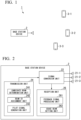
FIG. 1 ] A diagram illustrating a configuration example of acommunication system 1 according to a first embodiment. - [
FIG. 2 ] A diagram illustrating a configuration example of abase station device 2 according to the first embodiment. - [
FIG. 3 ] A diagram illustrating examples of candidate beams. - [
FIG. 4 ] A diagram illustrating examples of beam IDs assigned to the candidate beams. - [
FIG. 5 ] A diagram illustrating a relation example of a time frequency of a pilot signal transmitted from an antenna 21. - [
FIG. 6 ] A diagram illustrating a configuration example of aterminal device 3 according to the first embodiment. - [
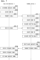
FIG. 7 ] A sequence diagram illustrating an operation of thecommunication system 1. -
FIG. 1 is a diagram illustrating a configuration example of acommunication system 1 according to a first embodiment. Thecommunication system 1 includes onebase station device 2 and a plurality of terminal devices 3 (for example, three terminal devices 3-1, 3-2, and 3-3). Thebase station device 2 communicate with theterminal devices 3. -
FIG. 2 is a diagram illustrating a configuration example of abase station device 2 according to the first embodiment. Thebase station device 2 includes an antenna 21, asignal conversion unit 22, atransmission unit 24, and areception unit 26. In thebase station device 2, thesignal conversion unit 22 converts a signal generated by thetransmission unit 24 into an analog signal and the antenna 21 transmits the analog signal. Thesignal conversion unit 22 converts an analog signal received via the antenna 21 into a digital signal, and thereception unit 26 processes the digital signal. - The
transmission unit 24 includes a candidatebeam determination unit 241, a beamID assignment unit 242, and a pilotsignal generation unit 243. - The candidate
beam determination unit 241 determines candidate beams that are candidates for a beam of a pilot signal to be transmitted for eachterminal device 3. For example, of the wide beams searched for using a wide beam with a large width, a beam with a finer range than the wide beam with the best reception sensitivity for eachterminal device 3 is determined as the candidate beam of thatterminal device 3. For example, the periphery of the beam used when thebase station device 2 transmits a signal for eachterminal device 3 is determined as the candidate beam of thisterminal device 3. The former method is performed, for example, when thebase station device 2 and theterminal device 3 have not performed communication previously. The latter method is performed, for example, when thebase station device 2 and theterminal device 3 have already performed communication. - The candidate
beam determination unit 241 may select several beams from the plurality of beams determined in advance for eachterminal device 3. - The number of candidate beams may differ for each
terminal device 3. -
FIG. 3 is a diagram illustrating examples of candidate beams. The candidatebeam determination unit 241 determines candidate beams 41-1 to 41-5 for the terminal device 3-1, candidate beams 42-1 to 42-4 for the terminal device 3-2, and candidate beams 43-1 to 43-4 for the terminal device 3-3. - The beam
ID assignment unit 242 assigns beam IDs to the candidate beams. The beamID assignment unit 242 assigns different beam IDs to the candidate beams of thesame terminal device 3. The beamID assignment unit 242 assigns beam IDs to candidate beams among the differentterminal devices 3 so that the number of combinations of the candidate beams to which the same beam ID is assigned is maximized. For example, in an example illustrated inFIG. 3 , the beamID assignment unit 242 assigns beam IDs of #1 to #5 to the candidate beams 41-1 to 41-5, assigns beam IDs of #1 to #4 to the candidate beams 42-1 to 42-4, and assigns beam IDs of #1 to #4 to the candidate beams 43-1 to 43-4. Accordingly, the beamID assignment unit 242 assigns different beam IDs to the candidate beams of the sameterminal device 3 and assigns the beam IDs to the candidate beams among the differentterminal devices 3 so that a combination of the candidate beams to which the same beam ID is assigned is a maximum of four (#1 to #4). - First, the beam
ID assignment unit 242 determines the number of beam IDs. The number of beam IDs is a maximum value of the number of candidate beams for eachterminal device 3. Thereafter, the beamID assignment unit 242 assigns the beam IDs sequentially from #1 for each candidate beam for eachterminal device 3. - When the candidate beams are duplicated among the
terminal devices 3, the beamID assignment unit 242 may assign the same beam ID to duplicated candidate beams. The fact that the candidate beams are duplicated means, for example, that an angle difference between centers of two beams is equal to or less than a predetermined angle. The candidatebeam determination unit 241 assign the same beam ID when the same candidate beams are selected among theterminal devices 3 in a case where several beams are selected for eachterminal device 3 from a plurality of beams determined in advance. - In the example illustrated in
FIG. 3 , the candidate beams 41-4 and 42-1 are duplicated, and the candidate beams 41-5 and 42-2 are duplicated. At this time, the beamID assignment unit 242 may assign the same beam ID to the candidate beams 41-4 and 42-1 and assign the same beam ID to the candidate beams 41-5 and 42-2.FIG. 4 is a diagram illustrating examples of beam IDs assigned to the candidate beams. The same beam ID of #1 may be assigned to the candidate beams 41-4 and 42-1 and the same beam ID of #2 may be assigned to the candidate beams 41-5 and 42-2. - The pilot
signal generation unit 243 generates pilot signals transmitted in the same time domain or the same frequency domain for each candidate beam to which the same beam ID is assigned. The pilotsignal generation unit 243 may generate the pilot signals to be transmitted simultaneously or pilot signals to be transmitted at the same frequency for each candidate beam to which the same beam ID is assigned. When the pilot signals to be transmitted in the same time domain or simultaneously are generated from the candidate beams to which the same beam ID is assigned, the pilotsignal generation unit 243 may generate the pilot signals to be transmitted in different frequency domains or at different frequencies for each candidate beam to which different beam IDs are assigned and may transmit the pilot signals generated based on the candidate beams to which the different beams ID are assigned in the same time domain or simultaneously. When the pilot signals to be transmitted in the same frequency domain or at the same frequency are generated from the candidate beams to which the same beam ID is assigned, the pilotsignal generation unit 243 may generate the pilot signals transmitted in the different time domains or at different timings for each candidate beam to which the different beam ID is assigned or may generate the pilot signals to be generated based on the candidate beams to which the different beam ID is assigned at the same frequency or in the same frequency domain. - The case where the pilot
signal generation unit 243 separately transmits the pilot signals in one of the time domain or the frequency domain by the number of different beam IDs has been described. However, the pilot signals may be separately transmitted in any time-frequency resources of the number of different beam IDs using both division of the time domain and division of the frequency domain. - When the same beam ID is assigned to the duplicated candidate beams, the pilot
signal generation unit 243 may not generate the pilot signals for each candidate beam or may generate one pilot signal collectively. When the same beam ID is assigned to the duplicated candidate beams, for example, the pilotsignal generation unit 243 may generate the pilot signals with one candidate beam among the plurality of duplicated candidate beams, may generate the pilot signals with the beam in a direction between the plurality of duplicated candidate beams, or may generate the pilot signals with the combined beam of the plurality of candidate beams. The pilotsignal generation unit 243 outputs the generated pilot signals to thesignal conversion unit 22. For example, the pilotsignal generation unit 243 generates the plurality of pilot signals and controls directions of the beams in which the pilot signals are transmitted from the antenna 21 by using a beamforming scheme of controlling phases of the generated pilot signals. Thesignal conversion unit 22 converts the pilot signals input from the pilotsignal generation unit 243 from digital signals to analog signals. The pilot signals converted into the analog signals are transmitted to theterminal device 3 via the antenna 21. The antenna 21 transmits the pilot signals with the beams in specific directions, for example, via a plurality of antennas (antennas 21-1, 21-2, and 21-3). -
FIG. 5 is a diagram illustrating a relation example of a time-frequency of a pilot signal transmitted from an antenna 21. The pilot signal is transmitted in the same frequency domain in a time-division manner for each beam ID. A direction in which the pilot signal is transmitted may depend on whether the candidate beams are duplicated. For example, since the candidate beams 41-4 and 42-1 are duplicated in the pilot signal generated based on the candidate beams to which the beam ID of #1 is assigned, two directions may be used. Since the candidate beams are not duplicated in the pilot signal generated based on the candidate beams to which the beam ID of #3 is assigned, three directions may be used. - In the example illustrated in
FIG. 5 , the pilot signal is transmitted in the same frequency domain in the time-division manner for each beam ID, but the present invention is not limited thereto. For example, the pilot signal may be transmitted in the same time domain in a frequency-division manner for each beam ID or the pilot signal may be transmitted both in the time-division manner and the frequency-division manner. - The pilot signal transmitted from the
base station device 2 may include information regarding the beam ID or may not include the information regarding the beam ID. For example, the pilotsignal generation unit 243 may generate pilot signal including the information regarding the beam ID based on the assignment of the beam ID by the beamID assignment unit 242 and output the pilot signal to thesignal conversion unit 22. When the pilot signal does not include the information regarding the beam ID, thebase station device 2 notifies of a transmission timing of the signal with each candidate beam, for example, by beforehand transmitting a timing at which transmission of the signal starts and information regarding a time interval at which the candidate beams are switched. - In the case of a method of generating the pilot signal including the information regarding the beam ID, since signals are transmitted with beams in a plurality of directions at the same time-frequency to the
terminal devices 3, there is a possibility of multipath interference occurring. Here, since the same pilot signal including the information regarding the same beam ID is transmitted in a plurality of directions at the same time-frequency, it is possible to prevent deterioration in signal quality due to interference in accordance with a multipath interface compensating method used for a general wireless communication system. In order to compensate for the multipath interference, a time difference in which signals are received with different beams transmitted from thebase station device 2 is required to be shorter than an allowable delay time difference of the multipath interference. That is, a time difference in which theterminal device 3 receives the plurality of same pilot signals transmitted at the same time-frequency is required to be shorter than an allowable delay time of the multipath interference. In the case of a method of generating the pilot signal that does not include the information regarding the beam ID, thebase station device 2 may not transmit the same pilot signal including the information regarding the same beam ID or may transmit different pilot signals since it is not necessary for theterminal device 3 to extract the information regarding the beam ID from the pilot signal. - Hereinafter, the
reception unit 26 will be described below in detail and a configuration of theterminal device 3 will be described.FIG. 6 is a diagram illustrating a configuration example of theterminal device 3 according to the first embodiment. Theterminal device 3 includes anantenna 31, asignal conversion unit 32, areception unit 34, and a feedbacksignal generation unit 36. Thereception unit 34 includes asignal processing unit 341, a receptionquality measurement unit 342, and a usage candidatebeam selection unit 343. - The
antenna 31 receives the pilot signal transmitted from thebase station device 2. Thesignal conversion unit 32 converts the pilot signal received by theantenna 31 from the analog signal to the digital signal. Thesignal processing unit 341 processes the pilot signal. Thesignal processing unit 341 acquires the beam ID included in the pilot signal, for example, by processing the pilot signal. - When the pilot signal does not include the information regarding the beam ID, the beam ID cannot be acquired from the pilot signal. Therefore, the
reception unit 34 acquires a transmission timing or the like in advance from thebase station device 2. For example, thereception unit 34 can acquire the timing at which the transmission of the signal starts and the timing at which each candidate beam is transmitted by acquiring the information regarding the time interval at which the candidate beam is switched and can estimate the beam ID corresponding to the received pilot signal. - The reception
quality measurement unit 342 measures reception quality of the pilot signal. The usage candidatebeam selection unit 343 selects the candidate beam to be used based on the reception quality of the pilot signal. The usage candidatebeam selection unit 343 selects, for example, the candidate beam corresponding to the pilot signal with the best reception quality as the candidate beam to be used. - The feedback
signal generation unit 36 generates the feedback signal to be transmitted to thebase station device 2. The feedback signal includes information regarding the candidate beam to be used, which is selected by the usage candidatebeam selection unit 343. The feedbacksignal generation unit 36 outputs the feedback signal to thesignal conversion unit 32. - The feedback signal is converted into the analog signal by the
signal conversion unit 32 and is transmitted from theantenna 31. - Referring back to
FIG. 2 , thereception unit 26 of thebase station device 2 will be described. Thereception unit 26 includes a feedbacksignal processing unit 261 and a usagebeam setting unit 262. - The feedback signal is received by the antenna 21 of the
base station device 2 and is converted into the digital signal by thesignal conversion unit 22. The feedbacksignal processing unit 261 processes the feedback signal and acquires the information regarding the candidate beam to be used. - The usage
beam setting unit 262 sets the beam to be used based on the information regarding the candidate beam to be used, which is included in the feedback signal. Thebase station device 2 sets the beam to be used during communication with eachterminal device 3 by receiving the feedback signal from eachterminal device 3. Thereafter, thebase station device 2 communicates with eachterminal device 3 by transmitting the signal to eachterminal device 3 with the set beam. -
FIG. 7 is a sequence diagram illustrating an operation of thecommunication system 1. First, the candidatebeam determination unit 241 of thebase station device 2 determines the candidate beams for each terminal device 3 (step S201). Thereafter, the beamID assignment unit 242 assigns the beam IDs to the candidate beams (step S202). Here, the beamID assignment unit 242 assigns the different beam IDs to the candidate beams of the sameterminal device 3 and assigns the beam IDs to the candidate beams among the differentterminal devices 3 so that the number of combinations of the candidate beams to which the same beam ID is assigned is maximized. When the candidate beam is duplicated between theterminal devices 3, the beamID assignment unit 242 may assign the same beam ID. Thereafter, the pilotsignal generation unit 243 generates the pilot signals, thesignal conversion unit 22 converts the pilot signals to the analog signals, and the converted analog signals are transmitted from the antenna 21 to the terminal device 3 (step S203). A transmission order of the pilot signals is based on the beam IDs. For example, the antenna 21 first transmits the pilot signal with the candidate beam of which the beam ID is #1 (step S203-1), subsequently transmits the pilot signal with the candidate beam of which the beam ID is #2 (step S203-2), and the pilot signals are continuously transmitted with all the candidate beams. - The
terminal device 3 receives the pilot signals using the antenna 31 (step S301) and thesignal conversion unit 32 converts the pilot signals from the analog signals to the digital signals. Thesignal processing unit 341 processes the pilot signals and acquires the information regarding the beam IDs (step S302). Here, when the received signals are unmodulated wave signals that do not include information regarding the beam IDs, thereception unit 34 acquires the timings at which the candidate beams are transmitted by acquiring the timings at which the transmission of the signals starts and the time intervals at which the candidate beams are switched, and estimates the beam IDs corresponding to the unmodulated wave signals. The receptionquality measurement unit 342 measures the reception quality of the received signals (step S303). Theterminal devices 3 perform operations of steps S301 to S303 whenever the pilot signals are received. For example, the terminal device 3-1 performs operations of steps S301-1 to S303-1 when the pilot signals transmitted with the candidate beams of which the beam IDs are #1 are received, performs operations of steps S301-2 to S303-2 when the pilot signals transmitted with the candidate beams of which the beam IDs are #2 are received, and performs operations on all the following pilot signals. The otherterminal devices 3 measure reception quality of all the transmitted pilot signals by performing the same operations. - The usage candidate
beam selection unit 343 selects the candidate beams to be used based on the reception quality (step S304). Thereafter, the feedbacksignal generation unit 36 generates the feedback signals including the information regarding the candidate beams to be used and thesignal conversion unit 32 converts the feedback signals into analog signals, and the converted analog signals are transmitted from the antenna 31 (step S305). The antenna 21 of thebase station device 2 receives the feedback signals (step S204), the signal conversion unit converts the feedback signals from the analog signals to the digital signals, the feedbacksignal processing unit 261 processes the feedback signals to acquire the information regarding usage candidate beams (step S205). The usagebeam setting unit 262 sets the beams to be used based on the information regarding the usage candidate beams in each terminal device 3 (step S206). - The
base station device 2 assigns the different beam IDs to the candidate beams for the sameterminal device 3 and assigns the beam IDs to the candidate beams between theterminal devices 3 so that the maximum number of same beam IDs are assigned. For each candidate beam to which the same beam ID is assigned, the pilot signals to be transmitted in the same time domain or same frequency domain are generated. Accordingly, it is possible to inhibit an increase in time and frequency resources associated with the increase in theterminal devices 3. - The
base station device 2 can assign the same beam ID to the duplicated candidate beam and transmit the pilot signal as one candidate beam. For example, with the candidate beams 41-4 and 42-1 that are duplicated candidate beams inFIG. 5 illustrating the time-frequency, the pilot signals are not transmitted with two candidate beams for eachterminal device 3 and one pilot signal is transmitted based on two candidate beams. Accordingly, it is possible to save the resources with which one pilot signal is transmitted from time T1 to time T2 and it is possible to save resources with which one pilot signal is transmitted from time T2 to time T3. In this way, thecommunication system 1 according to the present embodiment can save resources with which the signals are transmitted when thebase station device 2 selects the beams to be used for communication. - The embodiment of the present invention has been described in detail above with reference to the drawings. Specific configurations are not limited to the above-described configurations and various design modifications can be made within the scope of the present invention without departing from the gist of the present invention.
- Even in a configuration in which the
communication system 1 includes oneterminal device 3 and a plurality ofbase station devices 2, as in the embodiment, theterminal device 3 determines a candidate beam for eachbase station device 2, assigns a beam ID to the candidate beam for thebase station device 2, and generates a pilot signal, and thus it is possible to inhibit an increase in time and frequency resources. - The pilot signal can be replaced with a reference signal, a control signal, control information, or a control channel. The beam ID can also be notified of not only with the pilot signal but also the reference signal, the control signal, the control information, or the control channel.
- The beam ID may be information regarding a beam. The
terminal device 3 may be notified of the beam ID by using resource IDs of reference signals generated based on the candidate beams to which the same beam ID is assigned. - The
transmission unit 24 includes the candidatebeam determination unit 241, the beamID assignment unit 242, and the pilotsignal generation unit 243. Thereception unit 26 includes the feedbacksignal processing unit 261 and the usagebeam setting unit 262. Thereception unit 34 includes thesignal processing unit 341, the receptionquality measurement unit 342, and the usage candidatebeam selection unit 343. These constituent elements and the feedbacksignal generation unit 36 are realized, for example, by causing a hardware processor such as a central processing unit (CPU) to execute a program (software). Some or all of the constituent elements may be realized by hardware (including circuitry) such as a large scale integration (LSI), an application specific integrated circuit (ASIC), a field-programmable gate array (FPGA), or a graphics processing unit (GPU) or may be realized by software and hardware in combination. The program may be stored in advance in a storage device (a storage device including a non-transitory storage medium) such as a hard disk drive (HDD) or a flash memory or may be stored in a detachable storage medium such as a DVD or a CD-ROM (non-transitory storage medium) and installed when the storage medium is mounted on a drive device. -
- 1 Communication system
- 2 Base station device
- 3 Terminal device
- 21 Antenna
- 22 Signal conversion unit
- 24 Transmission unit
- 241 Candidate beam determination unit
- 242 Beam ID assignment unit
- 243 Pilot signal generation unit
- 26 Reception unit
- 261 Feedback signal processing unit
- 262 Usage beam setting unit
- 31 Antenna
- 32 Signal Conversion unit
- 34 Reception unit
- 341 Signal processing unit
- 342 Reception quality measurement unit
- 343 Usage candidate beam selection unit
- 36 Feedback signal generation unit
Claims (7)
- A base station device comprising:a candidate beam determination unit configured to determine candidate beams that are candidates for a beam of a pilot signal to be transmitted for each terminal device that is a transmission partner;a beam ID assignment unit configured to assign different beam IDs to the candidate beams of the same terminal device and assign beam IDs to candidate beams among different terminal devices so that the number of combinations of the candidate beams to which the same beam ID is assigned is maximized; anda pilot signal generation unit configured to generate a pilot signal to be transmitted in a same time domain and a same frequency domain for each candidate beam to which the same beam ID is assigned.
- The base station device according to claim 1, wherein, when the candidate beam is duplicated between the terminal devices, the beam ID assignment unit assigns the same beam ID to the duplicated candidate beam.
- The base station device according to claim 1 or 2, wherein the pilot signal generation unit generates a pilot signal including a corresponding beam ID.
- The base station device according to claim 1 or 2, wherein a difference between times at which a plurality of pilot signals transmitted in the same time domain are received in the terminal devices is less than a time difference of allowable delay of multi-path interference in the pilot signals.
- A communication system comprising:the base station device according to claim 1; anda plurality of terminal devices,wherein the terminal device includesa reception quality measurement unit that measures reception quality of a pilot signal,a usage candidate beam selection unit that selects a candidate beam to be used based on the reception quality and a correspondence relation between a pilot signal and a beam ID of a candidate beam, anda feedback signal generation unit that generates a feedback signal including information regarding the candidate beam to be used.
- A beam searching method comprising:a candidate beam determination step of determining candidate beams that are candidates for a beam of a pilot signal to be transmitted for each terminal device that is a transmission partner;a beam ID assignment step of assigning a different beam ID to the candidate beam of the same terminal device and assigning beam IDs to candidate beams among different terminal devices so that the number of combinations of the candidate beams to which the same beam ID is assigned is maximized; anda pilot signal generation step of generating a pilot signal to be transmitted in a same time domain and a same frequency domain for each candidate beam to which the same beam ID is assigned.
- A program causing a computer to operate as the base station device according to claim 1.
Applications Claiming Priority (1)
| Application Number | Priority Date | Filing Date | Title |
|---|---|---|---|
| PCT/JP2022/032247 WO2024042716A1 (en) | 2022-08-26 | 2022-08-26 | Base station device, communication system, beam search method, and program |
Publications (1)
| Publication Number | Publication Date |
|---|---|
| EP4580237A1 true EP4580237A1 (en) | 2025-07-02 |
Family
ID=90012858
Family Applications (1)
| Application Number | Title | Priority Date | Filing Date |
|---|---|---|---|
| EP22956542.9A Pending EP4580237A1 (en) | 2022-08-26 | 2022-08-26 | Base station device, communication system, beam search method, and program |
Country Status (3)
| Country | Link |
|---|---|
| EP (1) | EP4580237A1 (en) |
| JP (1) | JP7807556B2 (en) |
| WO (1) | WO2024042716A1 (en) |
Family Cites Families (4)
| Publication number | Priority date | Publication date | Assignee | Title |
|---|---|---|---|---|
| JP2017200004A (en) * | 2016-04-26 | 2017-11-02 | 富士通株式会社 | Radio communication device and beam search method |
| JP6984189B2 (en) | 2017-06-14 | 2021-12-17 | ソニーグループ株式会社 | Base station equipment, base station equipment control method, terminal equipment and terminal equipment control method |
| CN109586771A (en) | 2017-09-29 | 2019-04-05 | 索尼公司 | Electronic equipment and communication means |
| EP3598657B1 (en) | 2018-07-19 | 2021-06-09 | Mitsubishi Electric R & D Centre Europe B.V. | Method for configuring a mu-mimo wireless transmitter |
-
2022
- 2022-08-26 JP JP2024542561A patent/JP7807556B2/en active Active
- 2022-08-26 WO PCT/JP2022/032247 patent/WO2024042716A1/en not_active Ceased
- 2022-08-26 EP EP22956542.9A patent/EP4580237A1/en active Pending
Also Published As
| Publication number | Publication date |
|---|---|
| WO2024042716A1 (en) | 2024-02-29 |
| JPWO2024042716A1 (en) | 2024-02-29 |
| JP7807556B2 (en) | 2026-01-27 |
Similar Documents
| Publication | Publication Date | Title |
|---|---|---|
| JP6419817B2 (en) | NETWORK NODE, WIRELESS DEVICE AND METHOD THEREOF FOR TRANSMITTING AND DETECTING SYNC SIGNALS AND RELATED INFORMATION | |
| EP3017557B1 (en) | Methods and apparatus for sounding channel operation in millimeter wave communication systems | |
| US12395872B2 (en) | Radio communication method, radio communication system, radio base station, and reflector | |
| US20190296804A1 (en) | Double one-dimensional sector sweep scan | |
| US20140139372A1 (en) | Beam direction selection method and apparatus for use in beamforming system | |
| KR20180040368A (en) | Apparatus and method for beam searching based on antenna configuration in wireless communication system | |
| WO2020237534A1 (en) | Methods, devices and computer storage media for communication | |
| US12603806B2 (en) | Communication control apparatus, communication system, and method | |
| CN117015937A (en) | Transmission of reference signal resources | |
| KR102246608B1 (en) | Apparatus and method for controlling transmission power in a wireless communication system | |
| CN118018953A (en) | Wireless sensing method, information feedback method, device, storage medium and equipment | |
| US20240333344A1 (en) | Communication control method and communication control apparatus | |
| US20260046182A1 (en) | Method of adaptive transmission beam sweeping, method of controlling adaptive transmission beam sweeping, user equipment, base station and computer readable media | |
| US11218239B2 (en) | Operating method of terminal in wireless communication system and terminal for performing the method | |
| KR20230014554A (en) | Device and method for detecting irs service area | |
| CN119631345A (en) | SRS enhancement for interference randomization | |
| WO2017076311A1 (en) | System and method for large scale multiple input multiple output beamforming | |
| KR20240021002A (en) | method and apparatus for acquiring a beam book for RIS control in wireless communication system | |
| WO2020101756A2 (en) | Method and apparatus of antenna array group selection and antenna array selection for device communications | |
| US11509378B2 (en) | Apparatus search for optimal directional beams | |
| JP7807556B2 (en) | Base station device, communication system, beam search method and program | |
| WO2024174246A1 (en) | Devices, methods, and apparatuses for joint communication and sensing | |
| CN113938168B (en) | Split beam management method and system for uplink and downlink asymmetric communication MIMO system | |
| JP2020155894A (en) | User equipment and base station equipment | |
| CN121444359A (en) | Virtual Antenna Array Capability Report |
Legal Events
| Date | Code | Title | Description |
|---|---|---|---|
| STAA | Information on the status of an ep patent application or granted ep patent |
Free format text: STATUS: THE INTERNATIONAL PUBLICATION HAS BEEN MADE |
|
| PUAI | Public reference made under article 153(3) epc to a published international application that has entered the european phase |
Free format text: ORIGINAL CODE: 0009012 |
|
| STAA | Information on the status of an ep patent application or granted ep patent |
Free format text: STATUS: REQUEST FOR EXAMINATION WAS MADE |
|
| 17P | Request for examination filed |
Effective date: 20250221 |
|
| AK | Designated contracting states |
Kind code of ref document: A1 Designated state(s): AL AT BE BG CH CY CZ DE DK EE ES FI FR GB GR HR HU IE IS IT LI LT LU LV MC MK MT NL NO PL PT RO RS SE SI SK SM TR |
|
| RAP3 | Party data changed (applicant data changed or rights of an application transferred) |
Owner name: NTT, INC. Owner name: NTT DOCOMO, INC. |
|
| DAV | Request for validation of the european patent (deleted) | ||
| DAX | Request for extension of the european patent (deleted) |