EP4580207A1 - Bildgebung mit hohem dynamikbereich unter verwendung einer teilpolarisationsmaske - Google Patents
Bildgebung mit hohem dynamikbereich unter verwendung einer teilpolarisationsmaske Download PDFInfo
- Publication number
- EP4580207A1 EP4580207A1 EP24215720.4A EP24215720A EP4580207A1 EP 4580207 A1 EP4580207 A1 EP 4580207A1 EP 24215720 A EP24215720 A EP 24215720A EP 4580207 A1 EP4580207 A1 EP 4580207A1
- Authority
- EP
- European Patent Office
- Prior art keywords
- image
- photo
- filters
- polarisation
- image data
- Prior art date
- Legal status (The legal status is an assumption and is not a legal conclusion. Google has not performed a legal analysis and makes no representation as to the accuracy of the status listed.)
- Pending
Links
Images

Classifications
-
- H—ELECTRICITY
- H04—ELECTRIC COMMUNICATION TECHNIQUE
- H04N—PICTORIAL COMMUNICATION, e.g. TELEVISION
- H04N25/00—Circuitry of solid-state image sensors [SSIS]; Control thereof
- H04N25/10—Circuitry of solid-state image sensors [SSIS]; Control thereof for transforming different wavelengths into image signals
- H04N25/11—Arrangement of colour filter arrays [CFA]; Filter mosaics
- H04N25/13—Arrangement of colour filter arrays [CFA]; Filter mosaics characterised by the spectral characteristics of the filter elements
- H04N25/134—Arrangement of colour filter arrays [CFA]; Filter mosaics characterised by the spectral characteristics of the filter elements based on three different wavelength filter elements
-
- H—ELECTRICITY
- H04—ELECTRIC COMMUNICATION TECHNIQUE
- H04N—PICTORIAL COMMUNICATION, e.g. TELEVISION
- H04N23/00—Cameras or camera modules comprising electronic image sensors; Control thereof
- H04N23/60—Control of cameras or camera modules
- H04N23/67—Focus control based on electronic image sensor signals
- H04N23/672—Focus control based on electronic image sensor signals based on the phase difference signals
-
- H—ELECTRICITY
- H04—ELECTRIC COMMUNICATION TECHNIQUE
- H04N—PICTORIAL COMMUNICATION, e.g. TELEVISION
- H04N23/00—Cameras or camera modules comprising electronic image sensors; Control thereof
- H04N23/70—Circuitry for compensating brightness variation in the scene
- H04N23/741—Circuitry for compensating brightness variation in the scene by increasing the dynamic range of the image compared to the dynamic range of the electronic image sensors
-
- H—ELECTRICITY
- H04—ELECTRIC COMMUNICATION TECHNIQUE
- H04N—PICTORIAL COMMUNICATION, e.g. TELEVISION
- H04N23/00—Cameras or camera modules comprising electronic image sensors; Control thereof
- H04N23/70—Circuitry for compensating brightness variation in the scene
- H04N23/75—Circuitry for compensating brightness variation in the scene by influencing optical camera components
-
- H—ELECTRICITY
- H04—ELECTRIC COMMUNICATION TECHNIQUE
- H04N—PICTORIAL COMMUNICATION, e.g. TELEVISION
- H04N23/00—Cameras or camera modules comprising electronic image sensors; Control thereof
- H04N23/80—Camera processing pipelines; Components thereof
- H04N23/84—Camera processing pipelines; Components thereof for processing colour signals
- H04N23/843—Demosaicing, e.g. interpolating colour pixel values
-
- H—ELECTRICITY
- H04—ELECTRIC COMMUNICATION TECHNIQUE
- H04N—PICTORIAL COMMUNICATION, e.g. TELEVISION
- H04N25/00—Circuitry of solid-state image sensors [SSIS]; Control thereof
- H04N25/40—Extracting pixel data from image sensors by controlling scanning circuits, e.g. by modifying the number of pixels sampled or to be sampled
- H04N25/44—Extracting pixel data from image sensors by controlling scanning circuits, e.g. by modifying the number of pixels sampled or to be sampled by partially reading an SSIS array
- H04N25/445—Extracting pixel data from image sensors by controlling scanning circuits, e.g. by modifying the number of pixels sampled or to be sampled by partially reading an SSIS array by skipping some contiguous pixels within the read portion of the array
-
- H—ELECTRICITY
- H04—ELECTRIC COMMUNICATION TECHNIQUE
- H04N—PICTORIAL COMMUNICATION, e.g. TELEVISION
- H04N25/00—Circuitry of solid-state image sensors [SSIS]; Control thereof
- H04N25/48—Increasing resolution by shifting the sensor relative to the scene
-
- H—ELECTRICITY
- H04—ELECTRIC COMMUNICATION TECHNIQUE
- H04N—PICTORIAL COMMUNICATION, e.g. TELEVISION
- H04N25/00—Circuitry of solid-state image sensors [SSIS]; Control thereof
- H04N25/50—Control of the SSIS exposure
- H04N25/57—Control of the dynamic range
- H04N25/58—Control of the dynamic range involving two or more exposures
- H04N25/581—Control of the dynamic range involving two or more exposures acquired simultaneously
- H04N25/585—Control of the dynamic range involving two or more exposures acquired simultaneously with pixels having different sensitivities within the sensor, e.g. fast or slow pixels or pixels having different sizes
-
- H—ELECTRICITY
- H04—ELECTRIC COMMUNICATION TECHNIQUE
- H04N—PICTORIAL COMMUNICATION, e.g. TELEVISION
- H04N25/00—Circuitry of solid-state image sensors [SSIS]; Control thereof
- H04N25/70—SSIS architectures; Circuits associated therewith
- H04N25/703—SSIS architectures incorporating pixels for producing signals other than image signals
- H04N25/704—Pixels specially adapted for focusing, e.g. phase difference pixel sets
Definitions
- an imaging system comprising:
- an embodiment of the present disclosure provides a method comprising:
- the present disclosure provides the aforementioned imaging system and the aforementioned method utilising an image sensor incorporating a partial polarisation mask, to generate at least one of: the full-resolution colour image, the full-resolution polarisation image, the HDR image, in a highly realistic manner, and in computationally-efficient and time-efficient manner.
- the at least one processor to accurately capture the colour image data and the polarisation image data, in order to accurately reproduce colours (or unread/incomplete image data) in any of the aforesaid images, without compromising on image quality.
- the colour image data can be understood to be read out using a first setting (due to absence of the polarisation filters), whereas the polarisation image data can be understood to be read out using a second setting (due to presence of the polarisation filters), wherein the first setting and the second setting are two different settings that may pertain to at least one of: an exposure time, a sensitivity, an aperture size.
- this facilitates in generating the HDR image by processing the image data obtained for a single image, without requiring image data of at least two images (as in case of the prior art).
- the imaging system and the method are susceptible for generating HDR images along with fulfilling other requirements in XR devices, for example, such as small pixel size and high frame-rate requirements.
- the imaging system and the method are simple, robust, fast, reliable, supports real time HDR imaging using partial polarisation mask, and can be implemented with ease. It will be appreciated that in order to achieve the aforementioned technical benefits, the polarisation filters of the polarisation mask are arranged in a distributed manner across an entirety of the photo-sensitive surface.
- image sensor refers to a device that detects light from a real-world environment at the plurality of photo-sensitive cells (namely, a plurality of pixels) to capture a plurality of image signals.
- the plurality of image signals are electrical signals pertaining to a real-world scene of the real-world environment.
- the plurality of image signals constitute the image data of the plurality of photo-sensitive cells.
- Examples of the image sensor include, but are not limited to, a charge-coupled device (CCD) image sensor, and a complementary metal-oxide-semiconductor (CMOS) image sensor.
- CCD charge-coupled device
- CMOS complementary metal-oxide-semiconductor
- image data refers to information pertaining to a given photo-sensitive cell of the image sensor, wherein said information comprises at least one of: a colour value of the given photo-sensitive cell, a polarisation value of the given photo-sensitive cell.
- said information further comprises at least one of: a depth value of the given photo-sensitive cell, a transparency value of the given photo-sensitive cell, a luminance value (namely, a brightness value) of the given photo-sensitive cell.
- the visible-light camera examples include, but are not limited to, a Red-Green-Blue (RGB) camera, a Red-Green-Blue-Alpha (RGB-A) camera, a Red-Green-Blue-Depth (RGB-D) camera, an event camera, a Red-Green-Blue-White (RGBW) camera, a Red-Yellow-Yellow-Blue (RYYB) camera, a Red-Green-Green-Blue (RGGB) camera, a Red-Clear-Clear-Blue (RCCB) camera, a Red-Green-Blue-Infrared (RGB-IR) camera, and a monochrome camera.
- RGB Red-Green-Blue
- RGB-CB Red-Green-Blue-Infrared
- RGB-IR Red-Green-Blue-Infrared
- the polarization value is indicative of a polarization state of the light captured by the given photo-sensitive cell upon passing through a polarisation filter.
- the polarisation value could, for example, be expressed using at least one of: Stokes parameters, a degree of polarisation, a polarisation angle.
- the Stokes parameters comprise a set of four values 'I', 'Q', 'U', and 'V' that describe the polarization state of the light, wherein 'I' refers to a total intensity of the light, 'Q' and 'U' refer to linear polarization components, 'V' refers to a circular polarization component.
- the degree of polarisation is indicative of a portion of the light which is polarized, and typically lies in a range of 0 (indicating completely unpolarized light) to 1 (indicating fully polarized light).
- the degree of polarisation may be determined based on the Stokes parameters.
- the degree of polarisation encompasses at least a degree of linearly polarised light (DoLP).
- DoLP linearly polarised light
- the polarisation angle refers to an orientation of polarized light (that is typically measured in degrees).
- the polarization value and its representation are well-known in the art.
- the image data is RAW image data that has been read out from the image sensor.
- RAW image data refers to image data that is unprocessed (or may be minimally processed) when obtained from the image sensor.
- the image data is partially-processed image data that is generated upon performing certain image signal processing (ISP) on the RAW image data, for example, in an ISP pipeline.
- ISP image signal processing
- the image data and its forms are well-known in the art.
- the plurality of photo-sensitive cells could, for example, be arranged in a rectangular two-dimensional (2D) grid, a polygonal arrangement, a circular arrangement, an elliptical arrangement, a freeform arrangement, or the like, on the image sensor.
- the image sensor may comprise 25 megapixels arranged in the rectangular 2D grid (such as a 5000x5000 grid) on the photo-sensitive surface.
- the image data is read out in a line-by-line manner.
- colour filter array refers to a pattern of colour filters arranged in front of the plurality of photo-sensitive cells of the photo-sensitive surface, wherein the colour filter array (CFA) allows only specific wavelengths of light to pass through a given colour filter to reach a corresponding photo-sensitive cell of the photo-sensitive surface, for capturing corresponding image data.
- CFA colour filter array
- the CFA is well-known in the art.
- the photo-sensitive surface of the image sensor has millions of photo-sensitive cells.
- the CFA comprises a plurality of smallest repeating unit, wherein a given smallest repeating unit is a smallest grid of colour filters that is repeated throughout the CFA.
- the smallest repeating unit may be understood as a building block that gets repeated (for example, horizontally and/or vertically) to form an entirety of the CFA.
- the given smallest repeating unit may, for example, be an MxN array of colour filters.
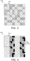
- a given portion of the CFA may comprise 12 smallest repeating units arranged in a 3x4 array, wherein a given smallest repeating unit from amongst the 12 smallest repeating units is a 3x2 array of colour filters.
- a given smallest repeating unit comprises 6 colour filters
- the CFA comprises 72 colour filters.
- the colour filters of the at least three different colours comprise at least one blue colour filter, at least one green colour filter, and at least one red colour filter.
- the at least one green colour filter could comprise at least two green colour filters.
- the colour filters of the at least three different colours could be similar to colour filters employed in a Bayer CFA.
- the Bayer CFA is well-known in the art.
- the colour filters of the at least three different colours comprise at least one cyan colour filter, at least one magenta colour filter, and at least one yellow colour filter.
- the at least one magenta colour filter could comprise at least two magenta colour filters.
- the CFA further comprises at least one other colour filter that allows to pass through at least one of: (i) at least three wavelengths corresponding to respective ones of the at least three different colours, (ii) at least one infrared wavelength.
- the at least one other colour filter that allows to pass through the at least three wavelengths simultaneously can be understood to be a white or near-white colour filter.
- the at least one other colour filter that allows to pass through the at least one infrared wavelength (for example, lying in an infrared wavelength range) can be understood to be an infrared colour filter.
- polarization mask refers to a physical mask comprising polarisation filters arranged on an optical path of corresponding colour filters, wherein a given polarisation filter allows light with only a specific polarization orientation to pass therethrough to reach a corresponding colour filter, while blocking light with other remaining polarization orientations.
- the polarisation mask and polarisation filters have been illustrated in conjunction with FIGs. 2 and 3 , for sake of better understanding and clarity.
- the colour filters on whose optical path the polarisation filters are arranged could have different colours from other colour filters.
- the polarisation filters are arranged on the optical path of colour filters having different colours, instead of the polarisation filters being arranged on the optical path of colour filters having a same colour.
- the first predefined percent lies in a range of 30 percent to 60 percent of the colour filters of the CFA. More optionally, the first predefined percent lies in a range of 40 percent to 50 percent of the colour filters of the CFA.
- the image data is processed by the at least one processor to generate at least one of: the full-resolution colour image, the full-resolution polarisation image, the HDR image.
- the term "colour image” refers to a visual representation of the real-world environment, wherein the visual representation encompasses colour information represented in the colour image, and additionally optionally other attributes (for example, such as depth information, luminance information, transparency information (namely, alpha values), and the like) associated with the colour image.
- polarisation image refers to a visual representation of the real-world environment, wherein the visual representation encompasses polarization information represented in the polarisation image, and additionally optionally other attributes associated with the polarisation image (for example, such as colour information, and the like).
- the polarization information may comprise intensity and polarization characteristics of light across a real-world scene of the real-world environment.
- polarisation images are employed in various applications, for example, such as material detection and segmentation (without any flares/reflections), visual inspection, remote sensing, detection of fine scratches on objects (due to contrast enhancement), stress recognition, object detection, and the like.
- full-resolution image refers to an image having a highest resolution (for example, in terms of pixel per degree (PPD)) that is obtainable from the image sensor.
- the highest resolution is the maximum possible resolution for the image sensor, and depends on the total number of photo-sensitive cells in the image sensor.
- image encompasses a colour image and/or a polarisation image.
- high-dynamic range image refers to an image having HDR characteristics. The HDR image represents a real-world scene being captured using a broader range of brightness levels, as compared to a standard image.
- the full-resolution colour image and/or the HDR image could, for example, be displayed to a user of a client device. Moreover, the full-resolution colour image and/or the HDR image may further be processed to generate an extended-reality (XR) image, to be shown to said user.
- the client device could be implemented, for example, as a head-mounted display (HMD) device.
- HMD head-mounted display
- the term "head-mounted display” device refers to specialized equipment that is configured to present an XR environment to a user when said HMD device, in operation, is worn by the user on his/her head.
- the HMD device is implemented, for example, as an XR headset, a pair of XR glasses, and the like, that is operable to display a visual scene of the XR environment to the user.
- extended-reality encompasses augmented reality (AR), mixed reality (MR), and the like.
- AR augmented reality
- MR mixed reality
- the colour image, the polarisation image, and the HDR image are well-known in the art.
- the image data that has been read out comprises image data corresponding to colour filters on whose optical path the polarisation filters are arranged as well as image data corresponding to remaining colour filters on whose optical path the polarisation filters are not arranged
- the at least one processor it is feasible for the at least one processor to accurately and realistically generate at least one of: the full-resolution colour image, the full-resolution polarisation image, the HDR image.
- the full-resolution colour image could be generated by utilising at least the image data corresponding to remaining colour filters on whose optical path the polarisation filters are not arranged (namely, colour image data), and optionally the image data corresponding to the colour filters on whose optical path the polarisation filters are arranged (namely, polarisation image data).
- the full-resolution polarisation image could be generated by utilising at least the polarisation image data, and optionally the colour image data.
- the HDR image could be generated by utilising the colour image data and the polarisation image data. This is because for the colour image data, those photo-sensitive cells that correspond to the remaining colour filters on whose optical path the polarisation filters are not arranged can be understood to be read out using a first setting (due to absence of the polarisation filters), whereas for the polarisation image data, those photo-sensitive cells that correspond to the colour filters on whose optical path the polarisation filters are arranged can be understood to be read out using a second setting (due to presence of the polarisation filters), wherein the first setting and the second setting are two different settings that may pertain to at least one of: an exposure time, a sensitivity, an aperture size. Beneficially, this facilitates in generating the HDR image (as discussed later).
- the at least one processor when processing the image data, is configured to perform interpolation and demosaicking on a part of the image data that is read out from those photo-sensitive cells that correspond to remaining colour filters on whose optical path the polarisation filters are not arranged, to generate the full-resolution colour image.
- said part of the image data is utilised for generating the full-resolution colour image, while another part of the image data that is read out from those photo-sensitive cells that correspond to the colour filters on whose optical path the polarisation filters are arranged may or may not be utilised (namely, taken into account) at all.
- said part of the image data comprises at least colour values of the photo-sensitive cells.
- the at least one processor is configured to perform the interpolation on said part of the image data (that is read out from those photo-sensitive cells that correspond to the remaining colour filters on whose optical path the polarisation filters are not arranged) for generating the full-resolution colour image.
- the "interpolation” is a specialized process of reconstructing unread image data of some photo-sensitive cells of the photo-sensitive surface by using image data read out from other photo-sensitive cells of the photo-sensitive surface. The interpolation would be required when the another part of the image data is not taken into account, and said part of the image data is still sufficient for generating the full-resolution colour image.
- the interpolation is well-known in the art.
- the at least one processor performs the interpolation by employing at least one interpolation algorithm.
- the at least one interpolation algorithm is at least one of: a bilinear interpolation algorithm, an edge-directed weighted-sum interpolation algorithm, a weighted sum interpolation algorithm, a local colour ratio (LCR) algorithm, a median-based interpolation algorithm, an average-based interpolation algorithm, a linear interpolation filtering algorithm, a cubic interpolation filtering algorithm, a four-nearest-neighbours interpolation filtering algorithm, a natural-neighbour interpolation filtering algorithm, a steering kernel regression interpolation filtering algorithm.
- LCR local colour ratio
- the aforesaid interpolation algorithms are well-known in the art.
- the HDR imaging technique comprises at least one of: an HDR tone-mapping technique, an HDR exposure bracketing technique, an HDR exposure fusion technique, a dual ISO technique, an edge-preserving filtering technique (for example, such as a guided image filtering technique).
- an HDR tone-mapping technique for example, a high-density HDR
- an HDR exposure bracketing technique for example, a high-density HDR
- an HDR exposure fusion technique for example, published in 15th Pacific Conference on Computer Graphics and Applications (PG'07), pp. 382-390, 2007 , which has been incorporated herein by reference.
- the interpolation and the demosaicking are performed using at least one neural network.
- the at least one processor when processing the image data, is configured to use the at least one neural network for performing the interpolation and the demosaicking, to generate at least one of: the full-resolution colour image, the full-resolution polarisation image, the HDR image, wherein an input of the at least one neural network comprises at least one of: said part of the image data, the another part of the image data.
- the at least one neural network performs the interpolation and the demosaicking in a highly accurate manner, as compared to conventional techniques.
- the term “wobulator” refers to a device that is capable of performing sub-pixel shifts.
- sub-pixel shift refers to a pixel-level movement (namely, a pixel-level shifting) of the image sensor (or light incoming towards the image sensor) in a particular direction, for capturing a given sub-image with the image sensor. It will be appreciated that a given sub-pixel shift could be performed, for example, by physically moving the image sensor and/or its corresponding optics (which may comprise optical elements, for example, such as lens, mirrors, and the like) by a given step size in a particular direction, or by optically steering the light (incoming towards the image sensor) by a given step size in a particular direction.
- optics which may comprise optical elements, for example, such as lens, mirrors, and the like
- two sub-images are obtained from the image sensor.
- the two (different) sub-images are captured by the image sensor using the one sub-pixel shift, wherein a first sub-image from amongst the two sub-images is captured when the image sensor is at its actual (namely, original) position (i.e., the first sub-image is captured when the image sensor or the light incoming towards the image sensor has not been shifted yet), and a second sub-image from amongst the two sub-images is captured when the image sensor or the light incoming towards the image sensor is shifted (i.e., moved) according to the one sub-pixel shift.
- three sub-images are obtained.
- the three (different) sub-images are captured by the image sensor using the two sub-pixel shifts, wherein a first sub-image from amongst the three sub-images is captured when the image sensor is at its actual position, a second sub-image from amongst the three sub-images is captured when the image sensor or the light incoming towards the image sensor is shifted according to one of the two sub-pixel shifts, and a third sub-image from amongst the three sub-images is captured when the image sensor or the light incoming towards the image sensor is shifted according to another of the two sub-pixel shifts.
- the camera when capturing the first sub-image and the second sub-image, it is ensured that either the camera (or the image sensor) is capturing sub-images of a static real-world environment (i.e., only stationary objects or their parts are present in the real-world environment), or a change in a relative pose between the camera and a given object or its part present in the real-world environment is minimal/negligible.
- visual representation represented in the first sub-image and the second sub-image would be significantly similar to each other, and thus it would be advantageous to generate at least one of: the full-resolution colour image, the full-resolution polarisation image, the HDR image, upon processing the first sub-image and the second sub-image.
- the at least one processor reads out those photo-sensitive cells that correspond to the remaining colour filters, and does not read out (namely, skips) those photo-sensitive cells that correspond to said colour filters. It will be appreciated that, for the first sub-image, sampling the first image data does not necessarily mean that all (i.e., 100 percent) of said photo-sensitive cells are read out. Thus, even when the aforesaid read out is performed only for a predefined percent (such as 95 percent or 99 percent) of said photo-sensitive cells, it should be considered as almost a full read out.
- first and second with respect to the first sub-image and the second sub-image are used to merely distinguish between two different sub-images. Usage of such terms in no way refer to an order in which these two different sub-images would be captured with the image sensor. In other words, it is not necessary that the first sub-image is always captured prior to capturing the second sub-image, or the second sub-image is always captured upon capturing the first sub-image. Therefore, it can be understood that the first sub-image may be captured before or after capturing the second sub-image.
- a processing time for reading out the first image data (for the first sub-image) and selectively reading out the second image data (for the second sub-image) is considerably lesser, as compared to a processing time for reading out image data from each and every photo-sensitive cell for two images.
- reading out (and processing) the first image data and the second image data in the aforesaid manner enables in achieving a high visual quality (for example, in terms of a native resolution, a high contrast, a realistic and accurate colour reproduction, low noise, and the like) in corresponding pixels of at least one image (that is generated upon processing the first sub-image and the second sub-image).
- the at least one image encompasses at least one of: the full-resolution colour image, the full-resolution polarisation image, the HDR image.
- the at least one processor is configured to process the first image data and the second image data together to generate the HDR image using the at least one neural network, wherein an input of the at least one neural network comprises at least the first image data and the second image data.
- the image sensor and/or its corresponding optics is shifted by a step size (of the sub-pixel shift) along a direction that is parallel to a longitudinal axis of a given smallest repeating unit, when said colour filters and the remaining colour filters are arranged in a plurality of smallest repeating units in the CFA.
- a given smallest repeating unit comprises at least a first sub-unit and a second sub-unit, the first sub-unit comprising colour filters of the at least three different colours.
- the second sub-unit comprises colour filters of the at least three different colours.
- the second sub-unit comprises colour filters of at least three other colours that are different from the at least three different colours.
- the longitudinal axis may refer to an axis along which the first sub-unit and the second sub-unit of the given smallest repeating unit are arranged relative to each other. It will be appreciated that when the first sub-unit and the second sub-unit of the given smallest repeating unit are vertically arranged with respect to each other, the longitudinal axis lies in a vertical direction, and the sub-pixel shift would be performed in the vertical direction. On the other hand, when the first sub-unit and the second sub-unit of the given smallest repeating unit are horizontally arranged with respect to each other, the longitudinal axis lies in a horizontal direction, and the sub-pixel shift would be performed in the horizontal direction.
- a step size of the sub-pixel shift is Y pixels, wherein Y is an integer that lies in a range from 1 to Z, Z being equal to a number of pixels that lie in the first sub-unit along said longitudinal axis.
- the term "step size" refers to an amount or a distance by which the image sensor or the light incoming towards the image sensor is shifted/moved along the longitudinal axis, in order to perform the sub-pixel shift.
- the step size is defined in terms of a number of photo-sensitive cells.
- the step size of the sub-pixel shift between at least two sub-images may be the image quality (for example, in terms of a resolution) of the at least one image that is generated upon processing the at least two sub-images, and vice versa.
- the step size is Y pixels, wherein Y is the integer that lies in the range from 1 to Z, it means that the step size is an integer step size, wherein when performing the sub-pixel shift, the image sensor (or the light incoming towards the image sensor) is shifted along said longitudinal axis by an amount defined by a size of one or more (complete) pixels that lie in the first sub-unit along said longitudinal axis.
- the technical benefit of employing such an integer step size is that it facilitates in achieving an effect of demosaicking without having to perform an actual (i.e., a full and regular) demosaicking on the image data.
- a sub-pixel shift having a step size of Y pixels would facilitate in capturing two sub-images (namely, the first sub-image and the second sub-image) in which a same photo-sensitive cell of the image sensor receives light from neighbouring 3D points in the real-world environment.
- This allows for capturing more detailed visual information of a real-world scene in the at least one image (that is generated from the first sub-image and the second sub-image) as compared to when only one sub-image is captured. Therefore, only a minimal demosaicking may actually be required when processing the two or more sub-images. In this way, upon said processing, the at least one image would be accurately and realistically generated.
- the at least one processor when processing the first sub-image and the second sub-image, is configured to perform the interpolation and the demosaicking on the first image data and the second image data, to generate at least one of: the full-resolution colour image, the full-resolution polarisation image, the HDR image.
- the interpolation is performed because the second image data is obtained (by the at least one processor) as subsampled image data.
- the demosaicking is performed to generate a set of complete colour information (for example, such as RGGB colour information or similar) for each pixel position.
- the at least one processor is configured to:
- the full-resolution polarisation image so generated would be very high quality, because it is generated based on polarisation data that is captured for all the photo-sensitive cells.
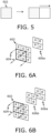
- the polarisation mask further comprises opaque masks arranged beside at least a second predefined percent of the polarization filters and on the optical path of corresponding colour filters, wherein in the image sensor, the opaque masks block light from passing towards a first part of each photo-sensitive cell in a first set of photo-sensitive cells and a second part of each photo-sensitive cell in a second set of photo-sensitive cells, and wherein the at least one processor is configured to:
- the term "opaque mask” refers to a physical mask that is capable of blocking light from passing towards a corresponding part of a given photo-sensitive cell, said physical mask being arranged beside a given polarisation filter in the polarisation mask and on an optical path of a corresponding colour filter in the CFA.
- the opaque masks are only arranged beside only some of the polarisation filters (as defined by the second predefined percent), and need not be arranged beside all of the polarisation filters.
- the polarisation filters may be arranged on the optical path of 50 percent (i.e., half) of the colour filters in the CFA, and the opaque masks may be arranged beside 50 percent (i.e., half) of such polarisation filters.
- the opaque masks may be arranged on the optical path of only 25 percent of the photo-sensitive cells. Therefore, only 25 percent of the photo-sensitive cells would be utilised for phase-detection auto focus (PDAF) (according to the aforementioned processing steps). It is to be noted that such a percentage of the photo-sensitive cells employed for the PDAF is significantly greater, as compared to a typical range, for example, from 5 percent to 10 percent, in conventional PDAF-based image sensors. Opaque masks have been also illustrated in conjunction with FIG. 4 , for sake of better understanding and clarity.
- the first part (namely, portion) of each photo-sensitive cell in the first set is one of a left part and a right part of each photo-sensitive cell
- the second part of each photo-sensitive cell in the second set is another of the left part and the right part of each photo-sensitive cell.
- the first part of each photo-sensitive cell in the first set is one of a top part and a bottom part of each photo-sensitive cell
- the second part of each photo-sensitive cell in the second set is another of the top part and the bottom part of each photo-sensitive cell.
- the first part and the second part are opposite parts.
- the plurality of image signals are optionally read out (namely, sampled) by the at least one processor from the plurality of photo-sensitive cells, for example, in a line-by-line (namely, sequential) manner.
- the plurality of image signals are read out in order to determine which photo-sensitive cells are not able to receive the light (namely, photons) at their respective first parts, and which photo-sensitive cells are not able to receive the light at their respective second parts.
- the at least one processor is configured to select the first photo-sensitive cell (from the first set) and the second photo-sensitive cell (from the second) such that the first photo-sensitive cell and the second photo-sensitive cell correspond to colour filters of two different colours, said colour filters being the ones on whose optical path both opaque masks and polarisation filters of a same type are arranged.
- the aforesaid selection could be a random selection.
- the at least one processor when selecting the plurality of pairs of photo-sensitive cells, is configured to select the first photo-sensitive cell and the second photo-sensitive cell such that both the first photo-sensitive cell and the second photo-sensitive cell correspond to colour filters of a same colour, said colour filters being the ones on whose optical path both opaque masks and polarisation filters of a same type are arranged.
- the at least one processor may select the plurality of pairs of photo-sensitive cells in a dynamic manner, for example, based on a lighting condition in the real-world environment.
- the phase difference is determined between the first image signal read out from the first photo-sensitive cell whose first part (for example, a left part) does not receive the light, and the second image signal read out from the second photo-sensitive cell whose second part (for example, a left part) does not receive the light.
- Said phase difference can be easily determined from the first image signal and the second image signal. Determining the phase difference from image signals is well-known in the art.
- the at least one processor could determine whether an object or its portion in a real-world scene of the real-world environment is in-focus or is out-of-focus (namely, blurred), and when said object or its portion is determined to be out-of-focus, the focus distance of the imaging system is adjusted accordingly.
- the at least one processor is configured to utilise a predefined correlation between the phase differences and the focus distance.
- the focus distance may be adjusted by adjusting an optical focus of the camera in a step-wise manner.
- a range of the focus distance is a range of optical depths at which the camera focuses within the real-world scene. Different cameras have different ranges of focus distance for different focus steps.
- the optical focus of the camera is adjusted to lie at a given optical depth.
- a total number of focus steps available for focussing are specific to a camera lens/optics of the camera.
- a number of focus steps is higher at smaller optical depths (namely, corresponding to nearby objects), as compared to larger optical depths (namely, corresponding to far-away objects).
- the number of focus steps could also be defined by a circle of confusion, and is well-known in the art.
- Techniques for example, a PDAF technique for adjusting the focus distance based on the phase differences are well-known in the art.
- the present disclosure also relates to the method as described above.
- the step of processing the image data comprises performing interpolation and demosaicking on a part of the image data that is read out from those photo-sensitive cells that correspond to remaining colour filters on whose optical path the polarisation filters are not arranged, to generate the full-resolution colour image.
- the interpolation and the demosaicking are performed on said part of the image data, based on another part of the image data that is read out from those photo-sensitive cells that correspond to the colour filters on whose optical path the polarisation filters are arranged.
- the step of processing the image data comprises performing interpolation and demosaicking on a part of the image data that is read out from those photo-sensitive cells that correspond to remaining colour filters on whose optical path the polarisation filters are not arranged, based on another part of the image data that is read out from those photo-sensitive cells that correspond to the colour filters on whose optical path the polarisation filters are arranged, using an HDR imaging technique, to generate the HDR image.
- the step of processing the image data comprises performing interpolation and demosaicking on said another part of the image data that is read out from those photo-sensitive cells that correspond to the colour filters on whose optical path the polarisation filters are arranged, to generate the full-resolution polarisation image.
- the interpolation and the demosaicking are performed on said another part of the image data, based on said part of the image data that is read out from those photo-sensitive cells that correspond to remaining colour filters on whose optical path the polarisation filters are not arranged.
- the interpolation and the demosaicking are performed using at least one neural network.
- the step of reading out the image data comprises obtaining a first sub-image and a second sub-image from the image sensor, the image data comprising first image data and second image data corresponding to the first sub-image and the second sub-image, respectively, wherein the step of obtaining comprises:
- step of processing the image data comprises processing the first sub-image and the second sub-image, to generate at least one of: the full-resolution colour image, the full-resolution polarisation image, the HDR image.
- the step of reading out the image data comprises obtaining a third sub-image and a fourth sub-image from the image sensor, the image data comprising third image data and fourth image data corresponding to the third sub-image and the fourth sub-image, respectively, wherein the step of obtaining comprises:
- step of processing the image data comprises processing the third sub-image and the fourth sub-image, to generate a full-resolution polarisation image.
- the polarisation mask further comprises opaque masks arranged beside at least a second predefined percent of the polarization filters and on the optical path of corresponding colour filters, wherein in the image sensor, the opaque masks block light from passing towards a first part of each photo-sensitive cell in a first set of photo-sensitive cells and a second part of each photo-sensitive cell in a second set of photo-sensitive cells,
- the imaging system 100 comprises an image sensor 102 and at least one processor (depicted as a processor 104).
- the image sensor 102 comprises a plurality of photo-sensitive cells 106, a colour filter array 108, and a polarisation mask 110.
- the imaging system 100 further comprises a wobulator 112.
- the processor 104 is communicably coupled to the image sensor 102 and, optionally, to the wobulator 112.
- the processor 104 is configured to perform various operations, as described earlier with respect to the aforementioned first aspect.
- FIG. 1 includes a simplified architecture of the imaging system 100, for sake of clarity, which should not unduly limit the scope of the claims herein. It is to be understood that the specific implementation of the imaging system 100 is provided as an example and is not to be construed as limiting it to specific numbers or types of image sensors, processors, photo-sensitive cells, colour filter arrays, wobulators, and polarisation masks. The person skilled in the art will recognize many variations, alternatives, and modifications of embodiments of the present disclosure.
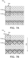
- FIG. 2 illustrated is a simplified perspective view of how a colour filter array (CFA) 202 and a polarisation mask 204 are arranged in an image sensor, in accordance with an embodiment of the present disclosure.
- CFA colour filter array
- a portion of the CFA 202 is shown to correspond to a portion of a photo-sensitive surface 206 of the image sensor.
- Said portion of the photo-sensitive surface 206 comprises 64 photo-sensitive cells (for example, depicted as some photo-sensitive cells 208) arranged in an 8x8 grid, and colour filters 210 in the shown portion of the CFA 202 are arranged in front of respective ones of the 64 photo-sensitive cells.
- CFA 202 refers to a blue colour filter
- G refers to a green colour filter
- R refers to a red colour filter.
- the shown portion of the CFA 202 comprises 64 colour filters arranged in an 8x8 array, wherein a given smallest repeating unit 212 (depicted as a 2x2 array of colour filters, using a dashed line box) is repeated throughout the CFA 202, and wherein the given smallest repeating unit 212 comprises two green colour filters, one red colour filter, and one blue colour filter.
- one sub-pixel shift is performed by a wobulator for capturing two sub-images.
- light 604 incoming from a real-world scene of a real-world environment is detected by the portion of the image sensor 602.
- a first sub-image 606a from amongst the two sub-images is captured when the image sensor 602 is at its existing (i.e., original) position.
- a second sub-image 606b from amongst the two sub-images is captured when the image sensor 602 (or the light 604) is shifted by a step size of one complete pixel in a vertically downward direction according to the one sub-pixel shift.
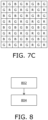
- the given smallest repeating unit 704 comprises a first sub-unit 710a (depicted using a dotted box) and a second sub-unit 710b (depicted using a dashed box), and the sub-pixel shifting is performed along the longitudinal axis 708 of the given smallest repeating unit 704.
- the first sub-unit 710a and the second sub-unit 710b are vertically arranged with respect to each other. Therefore, the longitudinal axis 708 lies along a vertical direction, and the sub-pixel shifting is performed in the vertical direction (in this particular case, in a vertically-downward direction 706).
Landscapes
- Engineering & Computer Science (AREA)
- Multimedia (AREA)
- Signal Processing (AREA)
- Physics & Mathematics (AREA)
- Spectroscopy & Molecular Physics (AREA)
- Color Television Image Signal Generators (AREA)
Priority Applications (1)
| Application Number | Priority Date | Filing Date | Title |
|---|---|---|---|
| EP25220755.0A EP4683342A2 (de) | 2023-12-27 | 2024-11-27 | Bildgebung mit hohem dynamikbereich unter verwendung einer teilpolarisationsmaske |
Applications Claiming Priority (1)
| Application Number | Priority Date | Filing Date | Title |
|---|---|---|---|
| US18/397,188 US20250220315A1 (en) | 2023-12-27 | 2023-12-27 | High-dynamic range imaging using partial polarisation mask |
Related Child Applications (1)
| Application Number | Title | Priority Date | Filing Date |
|---|---|---|---|
| EP25220755.0A Division EP4683342A2 (de) | 2023-12-27 | 2024-11-27 | Bildgebung mit hohem dynamikbereich unter verwendung einer teilpolarisationsmaske |
Publications (1)
| Publication Number | Publication Date |
|---|---|
| EP4580207A1 true EP4580207A1 (de) | 2025-07-02 |
Family
ID=93705005
Family Applications (2)
| Application Number | Title | Priority Date | Filing Date |
|---|---|---|---|
| EP25220755.0A Pending EP4683342A2 (de) | 2023-12-27 | 2024-11-27 | Bildgebung mit hohem dynamikbereich unter verwendung einer teilpolarisationsmaske |
| EP24215720.4A Pending EP4580207A1 (de) | 2023-12-27 | 2024-11-27 | Bildgebung mit hohem dynamikbereich unter verwendung einer teilpolarisationsmaske |
Family Applications Before (1)
| Application Number | Title | Priority Date | Filing Date |
|---|---|---|---|
| EP25220755.0A Pending EP4683342A2 (de) | 2023-12-27 | 2024-11-27 | Bildgebung mit hohem dynamikbereich unter verwendung einer teilpolarisationsmaske |
Country Status (2)
| Country | Link |
|---|---|
| US (1) | US20250220315A1 (de) |
| EP (2) | EP4683342A2 (de) |
Families Citing this family (1)
| Publication number | Priority date | Publication date | Assignee | Title |
|---|---|---|---|---|
| US20250191128A1 (en) * | 2023-12-07 | 2025-06-12 | Karl Storz Imaging, Inc | Mixed Latency Video System for Generating Images |
Citations (4)
| Publication number | Priority date | Publication date | Assignee | Title |
|---|---|---|---|---|
| JP2014164231A (ja) * | 2013-02-27 | 2014-09-08 | Olympus Imaging Corp | 撮像装置および焦点検出方法 |
| US20180302597A1 (en) * | 2015-06-10 | 2018-10-18 | Sony Corporation | Solid-state image capturing device and electronic device |
| US20200350353A1 (en) * | 2017-11-21 | 2020-11-05 | Sony Corporation | Image processing apparatus, image processing method, program, and solid-state imaging apparatus |
| US20210266425A1 (en) * | 2019-10-07 | 2021-08-26 | Sony Semiconductor Solutions Corporation | Electronic device |
Family Cites Families (5)
| Publication number | Priority date | Publication date | Assignee | Title |
|---|---|---|---|---|
| CN109804621B (zh) * | 2016-10-17 | 2020-11-17 | 索尼公司 | 图像处理装置、图像处理方法和图像拾取装置 |
| WO2020044928A1 (ja) * | 2018-08-31 | 2020-03-05 | ソニーセミコンダクタソリューションズ株式会社 | 撮像素子、撮像装置および撮像方法 |
| US10997690B2 (en) * | 2019-01-18 | 2021-05-04 | Ramot At Tel-Aviv University Ltd. | Method and system for end-to-end image processing |
| WO2020170565A1 (ja) * | 2019-02-19 | 2020-08-27 | ソニーセミコンダクタソリューションズ株式会社 | 信号処理方法および撮像装置 |
| WO2020213238A1 (ja) * | 2019-04-19 | 2020-10-22 | ソニー株式会社 | 撮像装置と画像処理装置および画像処理方法 |
-
2023
- 2023-12-27 US US18/397,188 patent/US20250220315A1/en active Pending
-
2024
- 2024-11-27 EP EP25220755.0A patent/EP4683342A2/de active Pending
- 2024-11-27 EP EP24215720.4A patent/EP4580207A1/de active Pending
Patent Citations (4)
| Publication number | Priority date | Publication date | Assignee | Title |
|---|---|---|---|---|
| JP2014164231A (ja) * | 2013-02-27 | 2014-09-08 | Olympus Imaging Corp | 撮像装置および焦点検出方法 |
| US20180302597A1 (en) * | 2015-06-10 | 2018-10-18 | Sony Corporation | Solid-state image capturing device and electronic device |
| US20200350353A1 (en) * | 2017-11-21 | 2020-11-05 | Sony Corporation | Image processing apparatus, image processing method, program, and solid-state imaging apparatus |
| US20210266425A1 (en) * | 2019-10-07 | 2021-08-26 | Sony Semiconductor Solutions Corporation | Electronic device |
Non-Patent Citations (2)
| Title |
|---|
| SHUTAO LI ET AL.: "Image Fusion with Guided Filtering", IEEE TRANSACTIONS ON IMAGE PROCESSING, vol. 22, no. 7, pages 2864 - 2875, XP011510936, DOI: 10.1109/TIP.2013.2244222 |
| T. MERTENS ET AL.: "Exposure Fusion", 2007, pages: 382 - 390 |
Also Published As
| Publication number | Publication date |
|---|---|
| US20250220315A1 (en) | 2025-07-03 |
| EP4683342A2 (de) | 2026-01-21 |
Similar Documents
| Publication | Publication Date | Title |
|---|---|---|
| US9215389B2 (en) | Image pickup device, digital photographing apparatus using the image pickup device, auto-focusing method, and computer-readable medium for performing the auto-focusing method | |
| CN102892008B (zh) | 双图像捕获处理 | |
| US8885026B2 (en) | Imaging device and imaging method | |
| CN102884802B (zh) | 三维成像装置和视点图像恢复方法 | |
| US9369693B2 (en) | Stereoscopic imaging device and shading correction method | |
| EP4241439B1 (de) | Blickbasierte nicht-reguläre unterabtastung von sensorpixeln | |
| US11688046B2 (en) | Selective image signal processing | |
| US12294789B2 (en) | Complementing wobulation in stereo cameras | |
| EP4580207A1 (de) | Bildgebung mit hohem dynamikbereich unter verwendung einer teilpolarisationsmaske | |
| JP7528051B2 (ja) | 改善された解像度を用いたプレノプティック・サブアパーチャ・ビュー・シャッフリング | |
| US12483804B2 (en) | Subsampling and wobulation in colour filter arrays having smallest repeating units with different sub-units | |
| US20250037239A1 (en) | Demosaicking and super-resolution using wobulation | |
| US20240314452A1 (en) | Foveating neural network | |
| US12244911B2 (en) | Image obtaining method and apparatus, terminal, and computer-readable storage medium having multiple panchromatic binnng modes | |
| US20250392833A1 (en) | Hallucinating colour filter array on image sensor chip | |
| US12256161B2 (en) | Simultaneous subsampling and high dynamic range imaging in multi-camera systems | |
| US12501181B2 (en) | Complementing subsampling in stereo cameras | |
| US12470843B2 (en) | Imaging with subsampling and wobulation | |
| US20250193543A1 (en) | Alternate subsampling in colour filter arrays | |
| US12328522B1 (en) | Selective reading and skipping in colour filter arrays | |
| US12432464B2 (en) | Adjustable colour filter array using liquid crystal device | |
| EP4598043A2 (de) | Simultane unterabtastung und bildgebung mit hohem dynamikbereich in farbfilterarrays | |
| US20250193542A1 (en) | Selective reading in colour filter arrays having smallest repeating units with different sub-units | |
| US20250221072A1 (en) | Interleaved colour filter array on image sensor chip | |
| US12530739B2 (en) | Interpolating and demosaicking subsampled pixels using neural networks |
Legal Events
| Date | Code | Title | Description |
|---|---|---|---|
| PUAI | Public reference made under article 153(3) epc to a published international application that has entered the european phase |
Free format text: ORIGINAL CODE: 0009012 |
|
| STAA | Information on the status of an ep patent application or granted ep patent |
Free format text: STATUS: THE APPLICATION HAS BEEN PUBLISHED |
|
| AK | Designated contracting states |
Kind code of ref document: A1 Designated state(s): AL AT BE BG CH CY CZ DE DK EE ES FI FR GB GR HR HU IE IS IT LI LT LU LV MC ME MK MT NL NO PL PT RO RS SE SI SK SM TR |
|
| STAA | Information on the status of an ep patent application or granted ep patent |
Free format text: STATUS: REQUEST FOR EXAMINATION WAS MADE |
|
| 17P | Request for examination filed |
Effective date: 20251204 |