EP4580198A1 - Bildverarbeitungsverfahren, hybridbildsensor, elektronische vorrichtung und speichermedium - Google Patents
Bildverarbeitungsverfahren, hybridbildsensor, elektronische vorrichtung und speichermedium Download PDFInfo
- Publication number
- EP4580198A1 EP4580198A1 EP23902659.4A EP23902659A EP4580198A1 EP 4580198 A1 EP4580198 A1 EP 4580198A1 EP 23902659 A EP23902659 A EP 23902659A EP 4580198 A1 EP4580198 A1 EP 4580198A1
- Authority
- EP
- European Patent Office
- Prior art keywords
- event
- frame
- readout
- image data
- camera
- Prior art date
- Legal status (The legal status is an assumption and is not a legal conclusion. Google has not performed a legal analysis and makes no representation as to the accuracy of the status listed.)
- Pending
Links
Images


Classifications
-
- H—ELECTRICITY
- H04—ELECTRIC COMMUNICATION TECHNIQUE
- H04N—PICTORIAL COMMUNICATION, e.g. TELEVISION
- H04N23/00—Cameras or camera modules comprising electronic image sensors; Control thereof
- H04N23/95—Computational photography systems, e.g. light-field imaging systems
-
- G—PHYSICS
- G06—COMPUTING OR CALCULATING; COUNTING
- G06T—IMAGE DATA PROCESSING OR GENERATION, IN GENERAL
- G06T7/00—Image analysis
- G06T7/30—Determination of transform parameters for the alignment of images, i.e. image registration
-
- H—ELECTRICITY
- H04—ELECTRIC COMMUNICATION TECHNIQUE
- H04N—PICTORIAL COMMUNICATION, e.g. TELEVISION
- H04N23/00—Cameras or camera modules comprising electronic image sensors; Control thereof
- H04N23/10—Cameras or camera modules comprising electronic image sensors; Control thereof for generating image signals from different wavelengths
- H04N23/11—Cameras or camera modules comprising electronic image sensors; Control thereof for generating image signals from different wavelengths for generating image signals from visible and infrared light wavelengths
-
- H—ELECTRICITY
- H04—ELECTRIC COMMUNICATION TECHNIQUE
- H04N—PICTORIAL COMMUNICATION, e.g. TELEVISION
- H04N23/00—Cameras or camera modules comprising electronic image sensors; Control thereof
- H04N23/10—Cameras or camera modules comprising electronic image sensors; Control thereof for generating image signals from different wavelengths
- H04N23/12—Cameras or camera modules comprising electronic image sensors; Control thereof for generating image signals from different wavelengths with one sensor only
-
- H—ELECTRICITY
- H04—ELECTRIC COMMUNICATION TECHNIQUE
- H04N—PICTORIAL COMMUNICATION, e.g. TELEVISION
- H04N23/00—Cameras or camera modules comprising electronic image sensors; Control thereof
- H04N23/10—Cameras or camera modules comprising electronic image sensors; Control thereof for generating image signals from different wavelengths
- H04N23/13—Cameras or camera modules comprising electronic image sensors; Control thereof for generating image signals from different wavelengths with multiple sensors
-
- H—ELECTRICITY
- H04—ELECTRIC COMMUNICATION TECHNIQUE
- H04N—PICTORIAL COMMUNICATION, e.g. TELEVISION
- H04N23/00—Cameras or camera modules comprising electronic image sensors; Control thereof
- H04N23/45—Cameras or camera modules comprising electronic image sensors; Control thereof for generating image signals from two or more image sensors being of different type or operating in different modes, e.g. with a CMOS sensor for moving images in combination with a charge-coupled device [CCD] for still images
-
- H—ELECTRICITY
- H04—ELECTRIC COMMUNICATION TECHNIQUE
- H04N—PICTORIAL COMMUNICATION, e.g. TELEVISION
- H04N23/00—Cameras or camera modules comprising electronic image sensors; Control thereof
- H04N23/50—Constructional details
- H04N23/54—Mounting of pick-up tubes, electronic image sensors, deviation or focusing coils
-
- H—ELECTRICITY
- H04—ELECTRIC COMMUNICATION TECHNIQUE
- H04N—PICTORIAL COMMUNICATION, e.g. TELEVISION
- H04N23/00—Cameras or camera modules comprising electronic image sensors; Control thereof
- H04N23/60—Control of cameras or camera modules
- H04N23/665—Control of cameras or camera modules involving internal camera communication with the image sensor, e.g. synchronising or multiplexing SSIS control signals
-
- H—ELECTRICITY
- H04—ELECTRIC COMMUNICATION TECHNIQUE
- H04N—PICTORIAL COMMUNICATION, e.g. TELEVISION
- H04N23/00—Cameras or camera modules comprising electronic image sensors; Control thereof
- H04N23/60—Control of cameras or camera modules
- H04N23/68—Control of cameras or camera modules for stable pick-up of the scene, e.g. compensating for camera body vibrations
- H04N23/681—Motion detection
- H04N23/6812—Motion detection based on additional sensors, e.g. acceleration sensors
-
- H—ELECTRICITY
- H04—ELECTRIC COMMUNICATION TECHNIQUE
- H04N—PICTORIAL COMMUNICATION, e.g. TELEVISION
- H04N23/00—Cameras or camera modules comprising electronic image sensors; Control thereof
- H04N23/60—Control of cameras or camera modules
- H04N23/68—Control of cameras or camera modules for stable pick-up of the scene, e.g. compensating for camera body vibrations
- H04N23/682—Vibration or motion blur correction
- H04N23/683—Vibration or motion blur correction performed by a processor, e.g. controlling the readout of an image memory
-
- H—ELECTRICITY
- H04—ELECTRIC COMMUNICATION TECHNIQUE
- H04N—PICTORIAL COMMUNICATION, e.g. TELEVISION
- H04N23/00—Cameras or camera modules comprising electronic image sensors; Control thereof
- H04N23/60—Control of cameras or camera modules
- H04N23/68—Control of cameras or camera modules for stable pick-up of the scene, e.g. compensating for camera body vibrations
- H04N23/682—Vibration or motion blur correction
- H04N23/685—Vibration or motion blur correction performed by mechanical compensation
- H04N23/687—Vibration or motion blur correction performed by mechanical compensation by shifting the lens or sensor position
-
- H—ELECTRICITY
- H04—ELECTRIC COMMUNICATION TECHNIQUE
- H04N—PICTORIAL COMMUNICATION, e.g. TELEVISION
- H04N23/00—Cameras or camera modules comprising electronic image sensors; Control thereof
- H04N23/60—Control of cameras or camera modules
- H04N23/698—Control of cameras or camera modules for achieving an enlarged field of view, e.g. panoramic image capture
-
- H—ELECTRICITY
- H04—ELECTRIC COMMUNICATION TECHNIQUE
- H04N—PICTORIAL COMMUNICATION, e.g. TELEVISION
- H04N23/00—Cameras or camera modules comprising electronic image sensors; Control thereof
- H04N23/70—Circuitry for compensating brightness variation in the scene
- H04N23/73—Circuitry for compensating brightness variation in the scene by influencing the exposure time
-
- H—ELECTRICITY
- H04—ELECTRIC COMMUNICATION TECHNIQUE
- H04N—PICTORIAL COMMUNICATION, e.g. TELEVISION
- H04N23/00—Cameras or camera modules comprising electronic image sensors; Control thereof
- H04N23/80—Camera processing pipelines; Components thereof
-
- H—ELECTRICITY
- H04—ELECTRIC COMMUNICATION TECHNIQUE
- H04N—PICTORIAL COMMUNICATION, e.g. TELEVISION
- H04N23/00—Cameras or camera modules comprising electronic image sensors; Control thereof
- H04N23/90—Arrangement of cameras or camera modules, e.g. multiple cameras in TV studios or sports stadiums
-
- H—ELECTRICITY
- H04—ELECTRIC COMMUNICATION TECHNIQUE
- H04N—PICTORIAL COMMUNICATION, e.g. TELEVISION
- H04N25/00—Circuitry of solid-state image sensors [SSIS]; Control thereof
- H04N25/47—Image sensors with pixel address output; Event-driven image sensors; Selection of pixels to be read out based on image data
-
- H—ELECTRICITY
- H04—ELECTRIC COMMUNICATION TECHNIQUE
- H04N—PICTORIAL COMMUNICATION, e.g. TELEVISION
- H04N25/00—Circuitry of solid-state image sensors [SSIS]; Control thereof
- H04N25/50—Control of the SSIS exposure
- H04N25/53—Control of the integration time
- H04N25/531—Control of the integration time by controlling rolling shutters in CMOS SSIS
-
- H—ELECTRICITY
- H04—ELECTRIC COMMUNICATION TECHNIQUE
- H04N—PICTORIAL COMMUNICATION, e.g. TELEVISION
- H04N25/00—Circuitry of solid-state image sensors [SSIS]; Control thereof
- H04N25/70—SSIS architectures; Circuits associated therewith
- H04N25/703—SSIS architectures incorporating pixels for producing signals other than image signals
- H04N25/707—Pixels for event detection
-
- H—ELECTRICITY
- H04—ELECTRIC COMMUNICATION TECHNIQUE
- H04N—PICTORIAL COMMUNICATION, e.g. TELEVISION
- H04N5/00—Details of television systems
- H04N5/04—Synchronising
- H04N5/06—Generation of synchronising signals
-
- G—PHYSICS
- G06—COMPUTING OR CALCULATING; COUNTING
- G06T—IMAGE DATA PROCESSING OR GENERATION, IN GENERAL
- G06T2207/00—Indexing scheme for image analysis or image enhancement
- G06T2207/10—Image acquisition modality
- G06T2207/10016—Video; Image sequence
-
- H—ELECTRICITY
- H04—ELECTRIC COMMUNICATION TECHNIQUE
- H04N—PICTORIAL COMMUNICATION, e.g. TELEVISION
- H04N13/00—Stereoscopic video systems; Multi-view video systems; Details thereof
- H04N13/20—Image signal generators
- H04N13/204—Image signal generators using stereoscopic image cameras
- H04N13/239—Image signal generators using stereoscopic image cameras using two two-dimensional [2D] image sensors having a relative position equal to or related to the interocular distance
Definitions
- This application relates to the field of imaging technologies, and in particular, to an image processing method, a hybrid image sensor, an electronic device, and a computer-readable storage medium.
- a camera of the electronic device is usually a conventional camera (for example, an RGB camera).
- the conventional camera has a poor imaging capability in some scenarios (for example, a motion scenario), and consequently, imaging experience of the user is poor.
- the first camera is configured to output first image data
- the second camera is configured to output second image data through the target pixel part, and output event data through the event pixel part
- the master chip is configured to: obtain the first image data, the second image data, and the event data; and send an image for display and/or store an image based on at least one of the first image data, the second image data, and the event data.
- an event camera is indirectly introduced into the electronic device in a hybrid image sensor (Hybrid sensor) manner, and the event data output by the event camera is added to the electronic device.
- Hybrid sensor Hybrid sensor
- introducing the event camera in a hybrid image sensor (Hybrid sensor) manner has the following advantages: related calculations such as focusing, electronic image stabilization, and optical image stabilization may be performed by using the second image data output by the hybrid image sensor, and then a lens is pushed to move, so that processes such as computational focusing and image stabilization do not need to be additionally performed on the event data, impact on an existing solution is smaller, and the solution is easier to be implemented.
- the first camera is a front-facing primary camera of the electronic device, and the second camera is a front-facing secondary primary camera of the electronic device; or the first camera is a rear-facing primary camera of the electronic device, and the second camera is a rear-facing secondary primary camera, a wide-angle camera, or a long-focus camera of the electronic device.
- the primary camera and the hybrid image sensor are used together, so that many limitations of the hybrid image sensor can be overcome or reduced.
- the hybrid image sensor is used as a secondary primary camera, a wide-angle camera, or a long-focus camera, and is used in combination with the primary camera, so that image imaging quality of the electronic device is not greatly reduced.
- a resolution requirement of the hybrid image sensor is not high, so that manufacturing costs are lower.
- a data amount of the event data is small, and may also be implemented under a camera bandwidth constraint of the electronic device. Therefore, implementation difficulty is low.
- the master chip is specifically configured to: perform binocular registration on the first image data and the second image data to obtain a registration matrix; perform registration on the first image data and the event data based on the registration matrix, to obtain registered first image data and registered event data; and send an image for display and/or store an image based on the registered first image data and the registered event data.
- image registration is performed on the first image data and the event data in a two-segment "bridge" registration manner, so that a registration deviation can be smaller.
- the first camera is the rear-facing primary camera
- the second camera is the wide-angle camera
- the master chip is specifically configured to: perform field of view-based cropping on the second image data based on a field of view of the first image data, to obtain cropped second image data; process the event data by using a preset wide-angle image processing algorithm, to obtain first processed event data; perform field of view-based cropping on the first processed event data based on the field of view of the first image data, to obtain cropped event data; perform binocular registration on the cropped second image data and the first image data, to obtain the registration matrix; and perform registration on the cropped event data and the first image data based on the registration matrix, to obtain the registered first image data and the registered event data.
- the master chip is further configured to: perform wide-angle distortion correction on the second image data, to obtain corrected second image data; process the event data by using the preset wide-angle image processing algorithm, to obtain second processed event data; and send an image for display and/or store an image based on the second processed event data and the corrected second image data.
- the first camera is the front-facing primary camera
- the second camera is the front-facing secondary primary camera
- the master chip is specifically configured to: perform wide-angle distortion correction on the first image data, to obtain processed first image data; perform wide-angle distortion correction on the second image data, to obtain processed second image data; process the event data by using a preset wide-angle image processing algorithm, to obtain third processed event data; perform binocular registration on the processed second image data and the processed first image data, to obtain the registration matrix; and perform registration on the third processed event data and the processed first image data based on the registration matrix, to obtain the registered first image data and the registered event data.
- the master chip is specifically configured to: generate a first stylized video or a first stylized picture based on the registered first image data and the registered event data, and send the first stylized video or the first stylized picture for display.
- the event data is superimposed on the first image data to form the stylized picture or video, so that more camera playing methods are provided for the user, and image experience of the user is better.
- the master chip is specifically configured to: generate a second stylized video or a second stylized picture based on the second image data and the event data, and send the second stylized video or the second stylized picture for display; or generate a third stylized video or a third stylized picture based on the event data, and send the third stylized video or the third stylized picture for display.
- the event data may be superimposed on the second image data to form the stylized picture or video, but also the stylized video or picture may be directly formed based on the event data. This provides more camera playing methods for the user, and provides better image experience for the user.
- the target pixel part includes a target pixel array and a target pixel readout circuit
- the event pixel part includes an event pixel array and an event pixel readout circuit
- the target pixel readout circuit is configured to perform an exposure operation and a readout operation on the target pixel array to obtain the second image data
- the event pixel readout circuit is configured to perform a readout operation on the event pixel array to obtain the event data.
- the hybrid image sensor further includes a pull-up circuit
- the target pixel readout circuit includes a frame readout controller
- the event pixel readout circuit includes a timestamping circuit
- the frame readout controller is connected to the pull-up circuit by using a hardware connection cable
- the pull-up circuit is connected to the timestamping circuit by using the hardware connection cable
- the frame readout controller is configured to output a frame synchronization signal
- the pull-up circuit is configured to receive the frame synchronization signal, and output a hard synchronization signal after performing voltage pull-up on the frame synchronization signal
- the timestamping circuit is further configured to: receive the hard synchronization signal, print an additional timestamp under triggering of the hard synchronization signal, and output the additional timestamp.
- the frame synchronization signal is derived via the frame readout controller, and is used as a standard moment of hard synchronization.
- hard synchronization and alignment of the second image data and the event data are implemented inside the hybrid image sensor, so that an image registration deviation can be further reduced, and stability of a peripheral circuit of the hybrid image sensor can be improved.
- a time synchronization effect is better and a time synchronization rate is faster because the target pixel part and the event pixel part use a same sensor clock signal.
- the event pixel readout circuit is further configured to embed the additional timestamp in a time sequence in an asynchronous event data stream, or embed the additional timestamp in a synchronous event frame data stream; and the event data is the asynchronous event data stream or the synchronous event frame data stream.
- the additional timestamp may be transmitted to the master chip through the event data stream, so that the additional timestamp can be transmitted to the master chip in a more timely manner. This reduces a waiting time of the master chip.
- the master chip is specifically configured to: receive the asynchronous event data stream or the synchronous event frame data stream; and perform time alignment between the event data and the second image data based on the additional timestamp in the asynchronous event data stream or the synchronous event frame data stream.
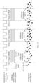
- the frame readout controller is specifically configured to: for each frame of second image data, separately output one frame synchronization signal at an exposure start time point and an exposure end time point; or if an exposure manner of the target pixel array is rolling shutter exposure, and a readout manner of the event pixel array is asynchronous readout, the frame readout controller is specifically configured to: for each frame of second image data, output one frame synchronization signal at an exposure end time point of a first row of target pixels.
- an exposure manner of the target pixel array is global shutter exposure, and a readout manner of the event pixel array is synchronous readout; and the frame readout controller is specifically configured to: for each frame of second image data, separately output one frame synchronization signal at an exposure start time point and an exposure end time point.
- an exposure manner of the target pixel array is global shutter exposure, and a readout manner of the event pixel array is synchronous readout;
- the frame readout controller is specifically configured to: for each frame period, separately output one frame synchronization signal at an exposure start time point and an exposure end time point, or output one frame synchronization signal at an exposure start time point, where the frame period is a time period from an exposure start time point of a current frame to an exposure start time point of a next frame;
- the event pixel readout circuit is further configured to: resynchronize a first event frame in the frame period with the hard synchronization signal corresponding to the exposure start time point, and embed the additional timestamp corresponding to the exposure start time point into the first event frame in the frame period.
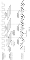
- an exposure manner of the target pixel array is rolling shutter exposure, and a readout manner of the event pixel array is synchronous readout; and the frame readout controller is specifically configured to: for each frame of second image data, output one frame synchronization signal at a preset moment, where the preset moment is an exposure end time point of a first row of target pixels or a start readout time point of a first row of target pixels.
- an exposure manner of the target pixel array is rolling shutter exposure, and a readout manner of the event pixel array is synchronous readout;
- the frame readout controller is specifically configured to: for each frame period, output one frame synchronization signal at an exposure end time point of a first row of target pixels, where the frame period is a time period from an exposure end time point of a first row of target pixels of a current frame to an exposure end time point of a first row of target pixels of a next frame;
- the event pixel readout circuit is further configured to: resynchronize a first event frame in the frame period with the hard synchronization signal corresponding to the exposure end time point of the first row of target pixels, and embed the additional timestamp corresponding to the exposure end time point of the first row of target pixels into a timestamp of the first event frame in the frame period.
- the frame readout controller is specifically configured to: for each frame of second image data, separately output one frame synchronization signal at an exposure start time point and an exposure end time point, or separately output one frame synchronization signal at an exposure end time point of a first row of target pixels.
- the master chip is further configured to: deliver a control signal to the hybrid image sensor, where the control signal includes a first readout parameter and a second readout parameter, the first readout parameter includes an exposure manner and an exposure time period, and the second readout parameter includes an event readout manner; and the hybrid image sensor is further configured to: receive the control signal, and parse the control signal to obtain the first readout parameter and the second readout parameter; based on the first readout parameter, control the target pixel readout circuit to perform an exposure operation and a readout operation to obtain the second image data, and control the frame readout controller to output the frame synchronization signal; and based on the second readout parameter, control the event pixel readout circuit to perform a readout operation to obtain the event data and the additional timestamp.
- the hybrid image sensor is further configured to: receive the control signal, and parse the control signal to obtain the first readout parameter and the second readout parameter; based on the first readout parameter, control the target pixel readout circuit to perform an exposure operation and a readout
- the master chip may further control a working process and an output result of the hybrid image sensor by delivering a sensor setting parameter.
- the sensor setting parameter is delivered, to control the frame readout controller to deliver the frame synchronization signal at a corresponding moment in different exposure manners and different readout manners, so as to implement hard synchronization between the second image data and the event data inside the hybrid image sensor in various cases.
- the master chip is further configured to: calculate a to-be-delivered sensor setting parameter based on the second image data and the event data, and generate the control signal based on the to-be-delivered sensor setting parameter.
- the readout manner of the event pixel array is synchronous readout
- an internal hard synchronization manner of the hybrid image sensor varies according to different application modes. For example, in the video mode and the photo mode, when the application mode is switched, a sensor setting parameter may be delivered to control a hard synchronization manner of the hybrid image sensor, so that a hard synchronization effect is better, and user image experience is better.
- the switching control signal is delivered within an exposure time period of an n th frame of second image data, and takes effect within an exposure time period of an (n+2) th frame of second image data.
- an embodiment of this application provides a hybrid image sensor, including a target pixel array, a target pixel readout circuit, an event pixel array, an event pixel readout circuit, and a pull-up circuit
- the target pixel readout circuit includes a frame readout controller
- the event pixel readout circuit includes a timestamping circuit
- the frame readout controller is connected to the pull-up circuit by using a hardware connection cable
- the pull-up circuit is connected to the timestamping circuit by using the hardware connection cable
- the target pixel readout circuit is configured to perform an exposure operation and a readout operation on the target pixel array, to output second image data
- the event pixel readout circuit is configured to perform a readout operation on the event pixel array, to output event data
- the frame readout controller is configured to output a frame synchronization signal
- the pull-up circuit is configured to receive the frame synchronization signal, and output a hard synchronization signal after performing voltage pull-up on the frame synchronization signal; and the timest
- the event pixel readout circuit is further configured to embed the additional timestamp in a time sequence in an asynchronous event data stream, or embed the additional timestamp in a synchronous event frame data stream; and the event data is the asynchronous event data stream or the synchronous event frame data stream.
- the additional time may be transmitted to the master chip through the event data stream, so that the additional timestamp can be transmitted to the master chip in a more timely manner. This reduces a waiting time of the master chip.
- the frame readout controller is specifically configured to: for each frame of second image data, separately output one frame synchronization signal at an exposure start time point and an exposure end time point; or if an exposure manner of the target pixel array is rolling shutter exposure, and a readout manner of the event pixel array is asynchronous readout, the frame readout controller is specifically configured to: for each frame of second image data, output one frame synchronization signal at an exposure end time point of a first row of target pixels.
- an exposure manner of the target pixel array is global shutter exposure, and a readout manner of the event pixel array is synchronous readout; and the frame readout controller is specifically configured to: for each frame of second image data, separately output one frame synchronization signal at an exposure start time point and an exposure end time point.
- an exposure manner of the target pixel array is global shutter exposure, and a readout manner of the event pixel array is synchronous readout;
- the frame readout controller is specifically configured to: for each frame period, separately output one frame synchronization signal at an exposure start time point and an exposure end time point, or output one frame synchronization signal at an exposure start time point, where the frame period is a time period from an exposure start time point of a current frame to an exposure start time point of a next frame;
- the event pixel readout circuit is further configured to: resynchronize a first event frame in the frame period with the hard synchronization signal corresponding to the exposure start time point, and embed the additional timestamp corresponding to the exposure start time point into the first event frame in the frame period.
- an exposure manner of the target pixel array is rolling shutter exposure, and a readout manner of the event pixel array is synchronous readout; and the frame readout controller is specifically configured to: for each frame of second image data, output one frame synchronization signal at an exposure end time point of a first row of target pixels.
- the frame readout controller is specifically configured to: for each frame of second image data, separately output one frame synchronization signal at an exposure start time point and an exposure end time point, or separately output one frame synchronization signal at an exposure end time point of a first row of target pixels.
- the hybrid image sensor is further configured to: receive a control signal from the master chip, and parse the control signal to obtain a first readout parameter and a second readout parameter; based on the first readout parameter, control the target pixel readout circuit to perform an exposure operation and a readout operation to obtain the second image data, and control the frame readout controller to output the frame synchronization signal; and based on the second readout parameter, control the event pixel readout circuit to perform the readout operation to obtain the event data and the additional timestamp, where the first readout parameter includes an exposure manner and an exposure time period, and the second readout parameter includes an event readout manner.
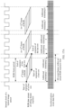
- an exposure manner of the target pixel array is rolling shutter exposure, and a readout manner of the event pixel array is synchronous readout; and the hybrid image sensor is further configured to: receive a switching control signal from a master chip, where the switching control signal is a signal generated after the master chip detects a switching operation, the switching operation indicates to switch from a video mode to a photo mode, and the switching control signal includes a sensor setting parameter in the photo mode; parse the switching control signal to obtain the sensor setting parameter in the photo mode; and control, based on the sensor setting parameter, the frame readout controller to: output one frame synchronization signal at an exposure start time point of a first row of target pixels of each frame of second image data, and output one frame synchronization signal at an exposure end time point of a last row of target pixels, so as to control the timestamping circuit to: print, in response to the hard synchronization signal, one additional timestamp at the exposure start time point of the first row of target pixels, print one additional timestamp
- the switching control signal is delivered within an exposure time period of an n th frame of second image data, and takes effect within an exposure time period of an (n+2) th frame of second image data.
- an embodiment of this application provides an image processing method.
- An electronic device includes a first camera and a second camera, the second camera includes a hybrid image sensor, and the hybrid image sensor includes a target pixel part and an event pixel part.
- the method includes: obtaining first image data output by the first camera; obtaining second image data output by the second camera through the target pixel part and event data output by the second camera through the event pixel part; performing registration on the first image data and the second image data to obtain a registration matrix; and performing registration on the first image data and the event data based on the registration matrix, to obtain registered first image data and registered event data.
- image registration is performed on the first image data and the event data in a two-segment "bridge" registration manner, so that a registration deviation can be smaller.
- the first camera is the rear-facing primary camera
- the second camera is the wide-angle camera
- the performing registration on the first image data and the second image data to obtain a registration matrix, and the performing registration on the first image data and the event data based on the registration matrix, to obtain registered first image data and registered event data include: performing field of view-based cropping on the second image data based on a field of view of the first image data, to obtain cropped second image data; processing the event data by using a preset wide-angle image processing algorithm, to obtain first processed event data; performing field of view-based cropping on the first processed event data based on the field of view of the first image data, to obtain cropped event data; performing binocular registration on the cropped second image data and the first image data, to obtain the registration matrix; and performing registration on the cropped event data and the first image data based on the registration matrix, to obtain the registered first image data and the registered event data.
- the first camera is the front-facing primary camera
- the second camera is the front-facing secondary primary camera
- the performing registration on the first image data and the second image data to obtain a registration matrix, and the performing registration on the first image data and the event data based on the registration matrix, to obtain registered first image data and registered event data include: performing wide-angle distortion correction on the first image data, to obtain processed first image data; performing wide-angle distortion correction on the second image data, to obtain processed second image data; processing the event data by using a preset wide-angle image processing algorithm, to obtain third processed event data; performing binocular registration on the processed second image data and the processed first image data, to obtain the registration matrix; and performing registration on the third processed event data and the processed first image data based on the registration matrix, to obtain the registered first image data and the registered event data.
- the method further includes: displaying a first stylized video or a first stylized picture based on the registered first image data and the registered event data.
- an embodiment of this application provides an electronic device, including a memory, a processor, and a computer program that is stored in the memory and that can be run on the processor.
- the processor executes the computer program, implements the method according to any possible implementation of the third aspect.
- an embodiment of this application provides a computer-readable storage medium.
- the computer-readable storage medium stores a computer program.
- the computer program is executed by a processor, the method according to any possible implementation of the third aspect is implemented.
- an embodiment of this application provides a chip system.
- the chip system includes a processor, the processor is coupled to a memory, and the processor executes a computer program stored in the memory, to implement the method according to any possible implementation of the third aspect.
- the chip system may be a single chip or a chip module including a plurality of chips.
- the hybrid image sensor may be used as a secondary primary camera, and is used together with a primary camera.
- the RGB data of the secondary primary camera is not directly used for imaging, and is only used in an image registration process. In this case, a requirement on resolution and imaging quality of the RGB data output by the hybrid image sensor is not high. Therefore, the quantity of event pixels in the hybrid image sensor may be appropriately increased, or even the RGB pixels in the hybrid image sensor may be replaced with black-and-white pixels.
- FIG. 3B is a diagram of another pixel arrangement.
- the pixel arrangement includes a black-and-white pixel 1, a black-and-white pixel 2, a black-and-white pixel 3, and an event pixel.
- FIG. 3C is a diagram of an overall circuit framework of a hybrid image sensor.
- FIG. 3C shows only one RGB pixel (or one black-and-white pixel) and one event pixel.
- the photosensitive element of the RGB pixel or the black-and-white pixel
- the photosensitive element of the event pixel is a PD 2.
- the PD 1 may perform read-out according to a normal RGB CMOS (or black-and-white CMOS) readout circuit. As shown in FIG. 3C , after light is transferred to the PD 1 through the lens, the PD 1 senses light to output a photosensitive current. After the photosensitive current is amplified by the AD 1, an amplified photosensitive current is output to the RGB readout circuit, and then the RGB readout current outputs an RGB data stream based on the photosensitive current.
- CMOS black-and-white CMOS
- the ON comparator circuit When the amplified voltage is greater than the specified threshold of the ON comparator circuit, it is considered that brightness sensed by the PD 2 increases, and when a brightness increase value reaches a specific threshold, the ON comparator circuit outputs a valid event signal, where the valid event signal represents a +1 event.
- the amplified voltage is greater than the specified threshold of the OFF comparator circuit, it is considered that brightness sensed by the PD 2 decreases, and when a brightness decrease value reaches a specific threshold, the OFF comparator circuit outputs a valid event signal, where the valid event signal represents a -1 event.
- the reset circuit may be triggered to take effect, a register circuit of the PD 2 is reset, and then exposure is restarted.
- the valid event signal triggered by the ON comparator circuit or the OFF comparator circuit is transmitted to the timestamping circuit and the addressing circuit, coordinate information and timestamp information of the event signal are printed, and the event data stream is output.
- a manner of reading out the event data may be synchronous readout or asynchronous readout. If the readout manner is asynchronous readout, the addressing circuit is required. If the readout manner is synchronous readout, the addressing circuit is not required.
- the event pixel readout circuit may include logic units such as a current logarithmic circuit, the AD 2, the ON comparator circuit, the OFF comparator circuit, a reset circuit, a timestamping circuit, and an addressing circuit.
- the logic units such as the current logarithmic circuit, the AD 2, the ON comparator circuit, the OFF comparator circuit, and the reset circuit exist in each event pixel, and the timestamping circuit and the addressing circuit are logic units shared by a plurality of event pixels.
- the overall circuit framework of the hybrid image sensor shown in FIG. 3C shows only the logic units, and electronic components such as a register circuit and a resistor may further exist between different logic units.
- electronic components such as a register circuit and a resistor may further exist between different logic units.
- there may be another logical unit.
- a column readout control unit and a row readout control unit may be further included, to control exposure and readout operations of event pixel rows and columns.
- the hybrid image sensor may be implemented in the spatial mixing manner, or may be implemented in a manner of customizing a special pixel.
- Customizing a special pixel means that a special pixel is set, the special pixel shares one photosensitive element, and two different readout circuits are integrated.
- One readout circuit is configured to change a current obtained through light sensing of the photosensitive element, to read out a normal RGB pixel value (or a black-and-white pixel value).
- the other readout circuit converts, by using the event pixel readout circuit, the change of the current obtained through light sensing of the photosensitive element into an event data stream with a microsecond-level time interval.
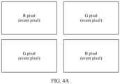
- FIG. 4A is a diagram of a pixel arrangement.
- the pixel arrangement includes an R pixel, a G pixel, a G pixel, and a B pixel, and each RGB pixel may also be used as an event pixel.
- the R pixel in FIG. 4A is not only used as an R pixel, but also may be used as an event pixel. In this case, one pixel may be used as both an event pixel and an RGB pixel. Therefore, the RGB pixel array 22 and the event pixel array 21 in FIG. 2 may be a same pixel array.
- an event pixel readout circuit 23 and an RGB readout circuit 24 are integrated into one pixel, and are respectively configured to read out event data and RGB data.
- FIG. 4A may alternatively be replaced with a black-and-white pixel.
- the special pixel is not only used as a black-and-white pixel, but also used as an event pixel.
- FIG. 4B is a diagram of another overall circuit framework of the hybrid image sensor. Only one pixel is shown in FIG. 4B , and a photosensitive element of the pixel is, for example, a PD 1.
- the pixel is not only used as an RGB pixel (or a black-and-white pixel), but also used as an event pixel.
- a visible light filter on each pixel in FIG. 4B is adapted to an RGB pixel.
- an infrared band light filter may be disposed on each pixel.
- log conversion is performed on the photosensitive current of the PD 1, to obtain a log voltage, and the log voltage is amplified by the AD 2, to obtain an amplified voltage.
- the amplified voltage is transmitted to the ON comparator circuit and the OFF comparator circuit, to trigger the ON comparator circuit or the OFF comparator circuit to output an event signal.
- address information and timestamp information are printed, and an event data stream is obtained.
- the photosensitive element is shared. Therefore, RGB data and event data that are output by the hybrid image sensor are naturally aligned, and no additional registration is required.
- an event pixel readout circuit and an RGB pixel readout circuit that are in the hybrid image sensor are independent of each other. Therefore, the event pixel may output a synchronous event frame with a high frame rate in a synchronous readout manner, or may output an asynchronous event data stream in an asynchronous readout manner.
- FIG. 4B shows only the logic units, and electronic components such as a register capacitor and a resistor may further exist between different logic units.
- the hybrid image sensor may have two mobile industry processor interfaces (mobile industry processor interface, MIPI) for transmission, to respectively transmit an RGB data stream and an event data stream.
- MIPI mobile industry processor interface
- the event data stream may further have a necessary compression algorithm before being output by the MIPI.
- RGB pixel and the black-and-white pixel uses the RGB pixel and the black-and-white pixel as an example to describe two pixel mixing manners: spatial mixing and customizing the special pixel, and an overall circuit framework inside the hybrid image sensor.
- a target pixel is an RYYB pixel, an IR pixel, or an NIR pixel
- spatial mixing, customizing a special pixel, and an overall circuit framework of the RGB pixel are similar to those of the target pixel.
- the G pixel in FIG. 3A may be adaptively a Y pixel.
- all RGB pixels in FIG. 3A may be replaced with IR pixels or NIR pixels.
- indirectly introducing the event camera into the electronic device in a form of a hybrid image sensor has the following advantages: related calculations such as focusing, electronic image stabilization, and optical image stabilization may be performed by using the second image data output by the hybrid image sensor, and then a lens is pushed to move, so that processes such as computational focusing and image stabilization do not need to be performed on the event data, impact on an existing solution is smaller, and the solution is easier to be implemented.
- the inventor further finds that, in a process of introducing the hybrid image sensor into the electronic device, the hybrid image sensor usually cannot be well introduced into the electronic device due to many limitations of the hybrid image sensor.
- the target pixel is an RGB pixel.
- an event pixel readout circuit is more complex than an RGB pixel readout circuit. Therefore, an area of a readout circuit of an event pixel is much larger than that of an RGB pixel (or a black-and-white pixel).
- a placement area of a readout circuit of one event pixel is larger than a placement area of a readout circuit of one RGB pixel. Based on this, if spatially placed side by side in the hybrid image sensor, one event pixel occupies positions of several R pixels, G pixels, or B pixels. This severely affects imaging quality of RGB pixels.
- the hybrid image sensor is directly introduced into the electronic device and used as a primary camera of the electronic device, because the placement area of the event pixel is much larger than the placement area of the RGB pixel, imaging quality of RGB data output by the hybrid image sensor is low, and consequently, RGB imaging quality on the electronic device like a mobile phone or a tablet computer is affected.
- an event resolution in the hybrid image sensor cannot be very high.
- an event resolution of a hybrid image sensor on an electronic device like a mobile phone or a tablet is far lower than a resolution of an RGB camera.
- an event resolution of the hybrid image sensor is less than 8M.
- the primary camera and the hybrid image sensor are used together, to overcome or reduce many limitations of the hybrid image sensor.
- the hybrid image sensor provided in embodiments of this application may be applied to an electronic device.
- the electronic device may be an intelligent mobile terminal such as a smartphone or a tablet computer, or may be another type of electronic device. This is not limited herein.
- the structure shown in this embodiment of this application does not constitute a specific limitation on the electronic device 500.
- the electronic device 500 may include more or fewer components than those shown in the figure, or some components may be combined, or some components may be split, or there may be a different component arrangement.
- the components shown in the figure may be implemented by hardware, software, or a combination of software and hardware.
- the processor 510 may include one or more processing units.
- the processor 510 may include an application processor (application processor, AP), a graphics processing unit (graphics processing unit, GPU), an ISP, a controller, a video codec, a digital signal processor (digital signal processor, DSP), and the like.
- Different processing units may be independent components, or may be integrated into one or more processors.
- the controller may generate an operation control signal based on an instruction operation code and a time sequence signal, to complete control of instruction reading and instruction execution.
- the processor 510 may include one or more interfaces.
- the interface may include an inter-integrated circuit (inter-integrated circuit, I2C) interface, a mobile industry processor interface (mobile industry processor interface, MIPI), a general-purpose input/output (general-purpose input/output, GPIO) interface, and the like.
- I2C inter-integrated circuit
- MIPI mobile industry processor interface
- GPIO general-purpose input/output
- the I2C interface is a two-way synchronization serial bus, and includes a serial data line (serial data line, SDA) and a serial clock line (serial clock line, SCL).
- the processor 510 may include a plurality of groups of I2C buses. The processor 510 may be coupled to the touch sensor through the I2C interface, so that the processor 510 communicates with the touch sensor through the I2C bus interface, to implement a touch function of the electronic device 500.
- the GPIO interface may be configured by software.
- the GPIO interface may be configured as a control signal or a data signal.
- the GPIO interface may be configured to connect the processor 510 to the first camera 530, the second camera 550, the display 540, and the like.
- the GPIO interface may be further configured as an I2C interface, an MIPI interface, or the like.
- the first camera 530 is usually a conventional camera, for example, an RGB camera.
- a type of the first camera 530 is not limited herein.
- the second camera 550 may include but is not limited to a lens and a hybrid image sensor.
- the lens includes one or more lenses
- the hybrid image sensor includes an event pixel and a target pixel.
- For related content of the hybrid image sensor refer to the foregoing corresponding content. Details are not described herein again.
- the first camera 530 when used as a primary camera of the electronic device 500, the first camera 530 may be used together with the second camera 550.
- the second camera 550 may be used as a secondary primary camera, a wide-angle camera, or a long-focus camera of the electronic device 500.
- the electronic device 500 may further include another camera.
- the electronic device 500 may further include at least one of the following: an RGB wide-angle camera, an RGB long-focus camera, an auxiliary camera, and the like.
- the memory 520 may be configured to store computer-executable program code.
- the executable program code includes instructions.
- the memory 520 may include a program storage area and a data storage area.
- the program storage area may store an operating system, an application required by at least one function (for example, a voice playing function or an image playing function), and the like.
- the data storage area may store data (for example, audio data and a phone book) and the like created when the electronic device 500 is used.
- the memory 520 may include a high-speed random access memory, and may further include a non-volatile memory, for example, at least one magnetic disk storage component, a flash memory component, or a universal flash storage (universal flash storage, UFS).
- the processor 510 runs the instructions stored in the internal memory 520 and/or the instructions stored in the memory disposed in the processor, to perform various function applications of the electronic device 500 and data processing.
- a field of view (Field of view, FOV) of the secondary primary camera 612 may be close to that of the primary camera 611.
- the primary camera 611 and the secondary primary camera 612 may share a camera support, and the primary camera 611 has an optical image stabilization (Optical Image Stabilization, OIS) component.
- OIS optical Image Stabilization
- the OIS component is also added to the secondary primary camera
- the primary camera 611 is an automatic focus (Automatic Focus, AF) lens
- the secondary primary camera 612 may be an AF lens or a fix focus (Fix Focus, FF) lens.
- the primary camera 611 has a variable aperture
- the secondary primary camera 612 may have a variable aperture or a fixed aperture.
- an additional camera module is added to the rear-facing camera module, the additional camera module is placed in a position of the hybrid image sensor, and the hybrid image sensor is used as a secondary primary camera.
- the wide-angle camera 622 is a camera including a hybrid image sensor, and the hybrid image sensor includes an event pixel and an RGB pixel (or a black-and-white pixel).
- the RGB wide-angle camera is replaced with the hybrid image sensor, and the hybrid image sensor is used as the wide-angle camera in the rear-facing camera module.
- parameters such as a pixel, an FOV, an OIS, an AF, an FF, and an aperture of the primary camera 621 and the wide-angle camera 622 may be set based on a requirement. This is not limited herein.
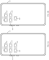
- FIG. 6C is a diagram of still another rear-facing camera module arrangement.
- the rear-facing camera module of the mobile phone 63 may include a primary camera 631, a wide-angle camera 632, a long-focus camera 633, and an auxiliary camera 634. Both the primary camera 631 and the wide-angle camera 632 are RGB cameras.
- the long-focus camera 633 is a camera including a hybrid image sensor, and the hybrid image sensor includes an event pixel and an RGB pixel (or a black-and-white pixel).
- the RGB long-focus camera is replaced with the hybrid image sensor, and the hybrid image sensor is used as the long-focus camera in the rear-facing camera module.
- parameters such as a pixel, an FOV, an OIS, an AF, an FF, and an aperture of the primary camera 631 and the long-focus camera 633 may be set based on a requirement. This is not limited herein.
- FIG. 6D is a diagram of a front-facing camera module arrangement.
- the front-facing camera module of the mobile phone 64 may include a primary camera 641, a secondary primary camera 642, and an auxiliary camera 643.
- the primary camera 641 is an RGB camera.
- the secondary primary camera 642 is a camera including a hybrid image sensor, and the hybrid image sensor includes an event pixel and an RGB pixel (or a black-and-white pixel). In other words, the hybrid image sensor is used as the secondary primary camera in the front-facing camera module.
- parameters such as a pixel, an FOV, an OIS, an AF, an FF, and an aperture of the primary camera 641 and the secondary primary camera 642 may be set based on a requirement. This is not limited herein.
- the electronic device 500 can have better RGB imaging quality, lower costs, and easier implementation.
- RGB image quality is greatly degraded. Even if the hybrid image sensor is implemented in the manner of customizing the special pixel, there is large crosstalk, and imaging quality of the RGB pixel and the event pixel is affected.
- a larger quantity of event pixels in the hybrid image sensor indicates a larger data amount of the event data output by the hybrid image sensor, and a higher camera bandwidth is required. Therefore, the event pixels of the hybrid image sensor are also limited. Under a camera bandwidth constraint (for example, an MIPI) of the electronic device, the resolution of the event pixel of the hybrid image sensor cannot be extremely high. Therefore, implementation difficulty is high.
- a camera bandwidth constraint for example, an MIPI
- the hybrid image sensor is used as the secondary primary camera, the wide-angle camera, or the long-focus camera, and is used together with the primary camera. Because RGB data of the hybrid image sensor is not directly used for imaging, even if RGB imaging quality of the hybrid image sensor is poor, RGB imaging quality of the electronic device 500 is not greatly reduced.
- the resolution of the hybrid image sensor used as the secondary primary camera, the wide-angle sensor, or the long-focus sensor does not need to be very high.
- a low-resolution hybrid image sensor has lower manufacturing costs, and a data volume of event pixels is small. This can also be implemented under the camera bandwidth constraint of an electronic device. Therefore, implementation difficulty is low.
- the electronic device 500 may perform corresponding processing on at least one of the first image data, the second image data, and the event data, and then send an image for display and/or store an image.
- the electronic device 500 may use the event data output by the second camera 550, to improve an imaging capability of the first camera for a motion scenario.
- the second image data and the event data that are output by the second camera 550 are usually not directly sent for display.
- the electronic device 500 performs, by using the event data output by the second camera 550, image deblurring (deblur) or video frame interpolation on the first image data output by the first camera 530, to obtain a to-be-displayed image or a to-be-displayed video stream.
- the display 540 of the electronic device 500 displays the to-be-displayed or the to-be-displayed video stream.
- more imaging modes may be provided for the user by using the event data and/or the second image data output by the second camera 550, to improve image experience of the user.
- the electronic device 500 may send the data output by the second camera 550 for display. Specifically, the electronic device 500 may separately send the event data for display, or may separately send the second image data for display, or may superimpose the event data and the first image data for display or superimpose the event data and the second image data for display.
- the electronic device 500 may add an "Event video" shooting mode. After the mode is entered, the electronic device 500 may display a stylized picture or a stylized video based on the second image data and/or the event data that are/is output by the second camera 550. This provides more playability for the user and improves user experience.
- a home screen 711 of the mobile phone 71 includes applications such as AI Life, Settings, Calendar, Clock, and Camera 712. After detecting a tap operation on the camera 712, the mobile phone 71 enters a photo mode in response to the tap operation, and displays a photo interface 713. Control buttons of shooting modes such as night, portrait, video, and event video 714 are displayed on the photo interface 713. After detecting a tap operation on the event video 714, the mobile phone 71 enters the "Event video" mode.
- the electronic device 500 starts the first camera 530 to perform photographing or video recording, and synchronously starts the second camera 550.
- the electronic device 500 starts only the first camera 530, and starts the second camera 550 when detecting the tap operation for the event video 714.
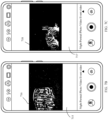
- the mobile phone 71 may perform frame compression on all event data output by the second camera 550 in a fixed time, to obtain a to-be-displayed image, and display the to-be-displayed image.
- the mobile phone 71 performs frame compression on original event data in a fixed time to obtain an image 716, and displays the image 716 in an interface 715.
- white represents a +1 event of an event pixel
- black represents a -1 event of the event pixel
- gray represents no event.
- the mobile phone 71 may synthesize some event data output by the second camera 550 in a fixed time period, to obtain a to-be-displayed image, and display the to-be-displayed image. For example, as shown in FIG. 7C , in the "Event video” mode, the mobile phone 71 synthesizes some event data within an RGB exposure time period to obtain an image 718, and displays the image 718 in the interface 717. In the image 718, white represents a +1 event of an event pixel, and black represents a -1 event of the event pixel.
- the fixed time is the RGB exposure time period of the first camera 530 or the second camera 550.
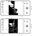
- the mobile phone 71 may alternatively synthesize all event data output by the second camera 550 in the fixed time period, to obtain a synthesized image, superimpose the synthesized image on the RGB image, to obtain a to-be-displayed image, and display the to-be-displayed image.
- the mobile phone 71 synthesizes all event data within an RGB complete exposure time period, to obtain a synthesized image, then superimposes the synthesized image on the RGB image, to obtain an image 720, and displays the image 720 in an interface 719.
- the mobile phone 71 may further superimpose, on an edge image, the event data output by the second camera 550, to obtain a to-be-displayed image, and display the to-be-displayed image.
- the edge image is generated based on the RGB image.
- the mobile phone 71 in the "Event video” mode, the mobile phone 71 superimposes the event image data on the edge image to obtain an image 722, and displays the image 722 in the interface 721.
- red represents a +1 event of an event pixel
- blue represents a -1 event of the event pixel
- a black-and-white image represents the edge image generated by the RGB image.
- the RGB image may be output by the first camera 530, or may be output by the second camera 550.
- the stylized video may be further made into a cartoon style or a sketch style, and may be specifically shown in the image 718 in FIG. 7C .
- the stylized video may also be used to predict movement tracks of some moving objects, and may be specifically shown in the image 720 in FIG. 7D .
- the stylized video may further form a motion smearing effect, which is similar to "stream light", and a color style of a motion region may be further modified, as shown in the image 722 in FIG. 7E .
- the mobile phone 71 may obtain a to-be-displayed video stream based on a plurality of consecutive frames of to-be-displayed images, so that the mobile phone 71 can output a stylized video in the "Event video" mode.
- the mobile phone 71 may also set an "Event image” mode, and output a stylized picture in this mode.
- colors of positive and negative polarities of the event data on the video may be customized by the user.
- a default color of positive and negative polarity events of the event data is red and blue.
- the user may adjust the default color to black and white or any other two contrast colors with an obvious difference as required. In this way, image experience of the user can be further improved.
- the electronic device 500 may output the event data to the user as a special video, or may superimpose the event data on an image video (for example, an RGB video), to form many stylized videos.
- a contour map may be extracted in real time from a scene currently seen by the user, to form a video like a comic or a sketch; or continuous motion recorded by the event camera is superimposed on a motion video recorded by the RGB camera, to form a special video with a high frame rate.
- the first image data and the event data need to be registered.
- the stylized video or the stylized picture is displayed based on the second image data and the event data, the second image data and the event data also need to be registered.
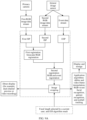
- the two-segment "bridge" registration manner includes two times of registration.
- the first registration is registration performed on the first image data output by the first camera 530 and the second image data output by the second camera 550; and the second registration is registration performed on the first image data output by the first camera 530 and the event data output by the second camera 550.
- the electronic device 500 first performs binocular registration on the first image data and the second image data to obtain a registration matrix H, and then performs registration on the first image data and the event data based on the registration matrix H to obtain registered first image data and registered event data.
- the preset parameter may include but is not limited to the following parameters: intrinsic and extrinsic parameter calibration data and other calibration parameters that are obtained through offline calibration of the primary camera and the hybrid image sensor; data fed back by a gyro sensor or an inertial measurement unit (Inertial Measurement Unit, IMU) in real time; real-time OIS data of the primary camera and the hybrid image sensor; focus motor stroke data of the primary camera and the hybrid image sensor; phase (Phase Detection, PD) focus data of the primary camera and the hybrid image sensor; and current focus depth data obtained by depth components such as a TOF and a laser.
- IMU inertial measurement unit
- the foregoing other calibration data may be, for example, related calibration parameters such as brightness and noise. After binocular RGB registration, differences between brightness, noise, colors, and the like of images of the primary camera and the hybrid image sensor at a same moment may be within a specific range by using the other calibration data.
- the electronic device 500 may obtain a registration matrix H, and then perform second registration by using the registration matrix H. Specifically, after the event data stream is processed by an event signal processor (Event Signal Processing, ESP), the event data stream processed by the ESP and the first RGB image data stream processed by the first ISP are registered based on the registration matrix H.
- Event Signal Processing Event Signal Processing
- a registered high-resolution RGB image data stream and a registered low-resolution event data stream may be obtained.
- the second camera 550 may be used as the front-facing secondary primary camera, the rear-facing secondary primary camera, the wide-angle camera, or the long-focus camera of the electronic device 500.
- a two-segment "bridge" registration process may vary with a role played by the second camera 550.
- wide-angle distortion correction further needs to be performed on an image obtained after ISP and ESP processing, to adapt to a wide-angle lens, and then FOV cropping is performed, to ensure that the first camera 530 and the second camera 550 have a same frame.
- the to-be-processed image data may be directly sent for display, that is, the electronic device 500 directly displays the to-be-processed image data in a viewfinder frame.
- the electronic device 500 uses the to-be-processed RGB image data as one preview video stream, uses the to-be-processed event data as another preview video stream, and simultaneously displays the two preview video streams in one interface, to implement dual-channel preview.
- the electronic device 500 may form, based on the to-be-processed RGB image data and the to-be-processed event data, the stylized video or the stylized picture shown in FIG. 7B to FIG. 7E ; or may transmit the to-be-processed image data to an application algorithm.
- the application algorithm processes the to-be-processed image data, and then sends the processed image data for display and storage.
- the application algorithm may include algorithms such as a deblur algorithm, a video frame interpolation algorithm, facial recognition, gesture recognition, and eyeball tracking. In this case, the algorithms such as facial recognition, gesture recognition, and eyeball tracking are implemented based on RGB data and event data.
- the focal length selected by the user may be, for example, 0.8X to 3.5X.
- the application algorithm may include a deblur algorithm, a video frame interpolation algorithm, and the like.
- the application algorithm may further include algorithms such as facial recognition, gesture recognition, and eyeball tracking based on RGB data and event data.
- the first camera 530 is used as the primary camera of the electronic device 500
- the second camera 550 is used as the wide-angle camera of the electronic device 500.
- FIG. 9B For example, refer to a diagram of another registration process shown in FIG. 9B . After two-segment "bridge" registration is performed on data output by the primary camera and data output by the hybrid image sensor, a high-resolution RGB image data stream and a low-resolution event data stream may be obtained. For a specific process, refer to related content in FIG. 8 . Details are not described herein again.
- a focal length selected by a user is 0.8X to 3.5X, that is, the focal length works in a primary focal length.
- a second ISP further performs a wide-angle FOV cropping operation to crop redundant picture content in a wide-angle RGB image.
- a wide-angle distortion correction algorithm is added to the second ISP to adapt to a wide-angle lens.
- a wide-angle distortion correction algorithm, an LSC algorithm, and a TSC algorithm for event data are further added to an ESP to adapt to the wide-angle lens.
- the ESP further performs event wide-angle FOV cropping, to crop an image that exceeds an FOV of the primary camera.
- a high-resolution RGB image data stream and a low-resolution event data stream that are of a same frame can be obtained through the two-segment "bridge" registration process.
- a process after the RGB image data stream and the event data stream that are of the same frame are obtained is similar to the process in FIG. 9A . Details are not described herein again.
- a focal length selected by the user is 0.6X to 0.8X, that is, works in a wide-angle focal length.
- the electronic device 500 may enable only the hybrid image sensor, process the second RGB image data stream and the event data stream that are output by the hybrid image sensor, and then perform operations such as image stabilization cropping and warping based on the focal length selected by the user and an EIS algorithm result. In this way, the high-resolution RGB image data stream and the event data stream that are registered in the wide-angle focal length are obtained.
- an RGB image wide-angle distortion correction algorithm may be added to the second ISP, and algorithms such as wide-angle distortion correction, LSC, and TSC for event data may be added to the ESP. It may be understood that the second RGB image data and the event data stream that are output by the hybrid image sensor are registered. Therefore, image registration does not need to be additionally performed through the two-segment "bridge" registration process.
- the first camera 530 is used as the primary camera of the electronic device 500
- the second camera 550 is used as the long-focus camera of the electronic device 500.
- the electronic device 500 may reduce a registration deviation through two-segment "bridge" registration. However, if time synchronization is not performed between the second image data and the event data that are output by the hybrid image sensor, and time synchronization is not performed between the first camera 530 and the second camera 550, there is still a specific registration deviation for the image data through two-segment "bridge" registration.
- the time synchronization manner may be classified into soft synchronization and hard synchronization.
- time synchronization may be performed on the second image data and the event data in a hard synchronization manner.
- hard synchronization may be performed on the second image data and the event data outside the hybrid image sensor.
- the hybrid image sensor includes a target pixel part and an event pixel part.
- the target pixel part may include but is not limited to a target pixel array, a target pixel readout circuit, and the like.
- the event pixel part may include but is not limited to an event pixel array and an event pixel array readout circuit.
- an interface for example, a GPIO interface
- the target pixel part and the event pixel part are connected based on the interface by using an external circuit, to implement hard synchronization between the second image data and the event data.
- the external circuit is disposed outside the hybrid image sensor.
- the target pixel part and the event pixel part may be considered as two independent image sensors, and the target pixel part and the event pixel part are connected by using an external circuit. This is equivalent to connecting the two independent image sensors in series.
- clock signals of the target pixel part and the event pixel part are different.
- hard synchronization may be implemented in a primary/secondary synchronization manner, that is, the target pixel part is used as a master (master), and the event pixel part is used as a slave (slave).
- hard synchronization may alternatively be performed on the second image data and the event data inside the hybrid image sensor.
- a frame readout controller inside the hybrid image sensor may provide a frame synchronization signal based on an exposure time period of the target pixel and a readout manner of the event data, and transfer the frame synchronization signal to a timestamping circuit in an event pixel readout circuit by using a hardware connection cable. In this way, the timestamping circuit is triggered to print an additional timestamp.
- the frame synchronization signal is used as a standard time for hardware synchronization.
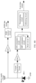
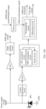
- the hybrid image sensor 100 may include but is not limited to: a target pixel array 101, a column readout controller 102, a row readout controller 103, a target pixel readout circuit 104, a frame readout controller 105, a pull-up circuit 106, an event pixel readout circuit 107, an event pixel array 108, a column readout controller 109, and a row readout controller 110.
- the frame readout controller 105 outputs a frame synchronization signal based on the exposure time period of the target pixel.
- the frame synchronization signal is transmitted to the pull-up circuit 106 by using a hardware connection cable.
- the pull-up circuit 106 After pulling up a voltage of the frame synchronization signal, the pull-up circuit 106 outputs a hard synchronization signal.
- the hard synchronization signal is transmitted to a timestamping circuit of the event pixel readout circuit 107 by using a hardware connection cable.
- the timestamping circuit prints a timestamp under triggering of the hard synchronization signal, and adds a mark as an external trigger (External trigger) timestamp to serve as an additional timestamp. In other words, the timestamping circuit may print an additional timestamp in response to the hard synchronization signal.
- an equivalent frame rate of the event data is very high, but a data transmission frequency of an interface like the I2C interface is much lower than a frame rate of the event data.
- the frame readout controller 105 may deliver a frame synchronization signal based on an exposure time period, and read out an image frame based on a frame rate.
- the exposure time period, the frame rate, and the like are setting parameters of the hybrid image sensor, and the setting parameters may be preset.
- the hybrid image sensor may work based on the setting parameters of the hybrid image sensor, and output the second image data, the event data, the additional timestamp, and the like.
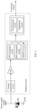
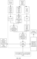
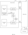
- FIG. 10D is a diagram of a framework of an imaging system of an electronic device 500.
- the imaging system includes a hybrid image sensor 100 and an SOC 200.
- the SOC 200 may be a main control chip system of the electronic device 500.
- the SOC 200 may integrate processors such as a central processing unit (central processing unit, CPU), an ISP, and an ESP.
- the SOC 200 may further integrate at least one of a storage unit, an interface unit, a system clock, a power supply unit, and the like.
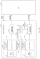
- the SOC 200 delivers a control signal to the hybrid image sensor 100.
- the control signal may include the hybrid image sensor setting.
- the hybrid image sensor setting includes but is not limited to the following control parameters: an exposure time period and an exposure manner of a target pixel, and a readout manner of an event pixel.
- the exposure manner includes global shutter (Global Shutter, GS) and rolling shutter (Rolling Shutter, RS).
- the exposure time period includes an exposure start time point and an exposure end time point.
- the readout manner includes asynchronous readout and synchronous readout.
- the hybrid image sensor 100 After receiving the control signal delivered by the SOC 200, the hybrid image sensor 100 signals the control signal to obtain a corresponding control parameter, controls, based on the corresponding control parameter, the hybrid image sensor to work, and outputs the second image data, the event data, the additional timestamp, and the like.
- control parameters such as an exposure time period, an exposure manner, and a readout manner are obtained
- exposure of the target pixel array 101 is controlled based on the exposure time period and the exposure manner
- the target pixel readout circuit 104 is controlled to perform a readout operation to obtain the second image data.
- the event pixel readout circuit 107 is controlled, based on the readout manner, to read out an event, to obtain the event data.
- the frame readout controller 105 further outputs a frame synchronization signal based on an exposure time period, an exposure manner, and the like, to trigger the timestamping circuit in the event pixel readout circuit 107 to print an additional timestamp.
- the target pixel is an RGB pixel
- the second image data is RGB data
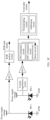
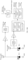
- FIG. 11 is a diagram of another framework of an imaging system of an electronic device 500.
- the imaging system may include a hybrid image sensor 1101 and an SOC 1102. RGB data and event data are respectively transmitted between the hybrid image sensor 1101 and the SOC 1102 through two MIPI interfaces, and the SOC 1102 transmits a control signal to the hybrid image sensor 1101 through an I2C interface.
- the RGB pixel part includes but is not limited to an RGB pixel array 1103, a column readout controller 1104, a row readout controller 1105, a frame readout controller 1106, an AMP amplifier 1107, an ADC 1108, an on-chip ISP 1109, and an MIPI transmit end 1110.
- a pixel array, a readout circuit, and the like of the RGB pixel part may be the same as or similar to a pixel array, a readout circuit, and the like of the RGB image sensor.
- the RGB pixel readout circuit includes an AMP amplifier 1107 and an ADC 110.
- the event pixel part includes but is not limited to an event pixel array 1113, a column readout controller 1114, a row readout controller 1115, an event pixel readout circuit 1112, an on-chip ESP 1116, and an MIPI transmit end 1117.
- the RGB pixel part and event pixel part are controlled by a sensor clock in the hybrid image sensor.
- the event pixel part may perform frequency multiplication on the sensor clock. That is, the RGB pixel part and event pixel part share the same clock.
- the RGB pixel part and the event pixel part are connected by using a pull-up circuit 1111.
- the frame readout controller 1106 is connected to the pull-up circuit 1111 by using a hardware connection cable
- the pull-up circuit 1111 is connected to the event pixel readout circuit 1112 by using a hardware connection cable, and may be specifically connected to a timestamping circuit in the event pixel readout circuit 1112.
- the event pixel readout circuit 1112 refer to FIG. 10B and FIG. 10C . Details are not described herein again.
- the SOC 1102 may include an MIPI receive end 1118, a hardened ESP 1119, an MIPI receive end 1120, a hardened ISP 1121, a software-based algorithm 1122, and an application algorithm 1123.
- a control instruction register 1124 of the hybrid image sensor 1101 may receive a control signal delivered by the SOC 1102, and control, based on the control signal, each unit in the hybrid image sensor to work, to output RGB data, event data, and an additional timestamp.
- the control signal may be transmitted by the SOC 1102 to the control instruction register 1124 through the I2C interface.
- control signal delivered by the SCO 1102 may include at least one of the following control parameters: hybrid image sensor setting, an on-chip ISP algorithm parameter or an on-chip ESP algorithm parameter, an MIPI transmission parameter of RGB data, an MIPI transmission parameter of the event data, one time programmable (One Time Programmable, OTP) information, and the like.
- the hybrid image sensor setting may include but is not limited to an RGB readout parameter and an event readout parameter.
- the RGB readout parameter may include an RGB exposure manner, an exposure time period, an RGB gain, a quantity of bits, and the like.
- the exposure time period may include an exposure start time point and an exposure end time point.
- the event readout parameter may include an event readout manner, a filter parameter of an analog end of each event pixel, a comparison threshold, a refractory period (refractory period) of a reset circuit, a trigger manner and a trigger moment of a hard synchronization signal, and the like.
- control instruction register 1124 transmits instruction code corresponding to the RGB gain to the AMP amplifier 1107 based on the instruction address, and the AMP amplifier 1107 outputs a result based on the delivered RGB gain in response to the instruction code.
- the RGB gain of the AMP amplifier 1107 can be controlled based on the control signal.
- control instruction register 1124 transmits, based on the instruction address, instruction code corresponding to the quantity of bits to the ADC 1108, and the ADC 1108 performs analog-to-digital conversion in response to the instruction code based on the quantity of delivered bits. In this way, the quantity of bits of the ADC 1108 can be controlled based on the control signal.
- control instruction register 1124 transmits, based on the instruction address, instruction code corresponding to the on-chip ISP algorithm parameter to the on-chip ISP 1109, and transmits instruction code corresponding to the MIPI transmission parameter of the RGB data to the MIPI transmit end 1110.
- the on-chip ISP 1109 runs a corresponding algorithm based on the on-chip ISP algorithm parameter.
- the MIPI transmit end 1110 controls an MIPI packaging manner, an MIPI transmission mode, a transmission rate, and the like of the RGB data stream based on the MIPI transmission parameter.
- control instruction register 1124 transmits, based on the instruction address, instruction code corresponding to the on-chip ESP algorithm parameter to the on-chip ESP 1116, and transmits instruction code corresponding to the MIPI transmission parameter of the event data to the MIPI transmit end 1117.
- the on-chip ISP 1116 runs a corresponding algorithm based on the on-chip ISP algorithm parameter in response to the instruction code.
- the MIPI transmit end 1117 controls an MIPI packaging manner, an MIPI transmission mode, a transmission rate, and the like of the event data stream based on the MIPI transmission parameter.
- the on-chip ISP 1109 may be integrated with an on-chip ISP algorithm pipe.
- an on-chip dead pixel correction (dead pixel correction, DPC) algorithm, a remoscia algorithm or a demoscia algorithm, and an automatic white balance (Auto White Balance, AWB) algorithm are integrated into the on-chip ISP 1109.
- the DPC algorithm on the on-chip ISP 1109 may be different from a DPC algorithm of a conventional RGB image sensor.
- the on-chip ISP 1109 runs a DPC algorithm occupied by an event pixel and a DPC algorithm for a conventional RGB pixel.
- the DPC algorithm occupied by the event pixel and the DPC algorithm for the conventional RGB pixel may be in a serial relationship or a parallel relationship.
- the on-chip ISP algorithm increases missing of a part of RGB pixel caused by occupation of the event pixel.
- each event pixel is a dead pixel. Therefore, the DPC algorithm occupied by the event pixel is implemented in the on-chip ISP.
- the on-chip ESP algorithm pipe may be integrated into the on-chip ESP 1116.
- the on-chip ESP algorithm may include, for example, algorithm modules such as DPC (dead/hot pixel correction), event rate control, and event compression of the event pixel.
- DPC dead/hot pixel correction
- event rate control event rate control
- event compression event compression of the event pixel.
- different modes and a related algorithm parameter in the on-chip ESP algorithm pipe in the hybrid image sensor may be controlled through the control signal delivered by the I2C.
- the RGB data and the event data that are output by the hybrid image sensor 1101 are separately transmitted to the SOC 1102 by using the MIPI.
- the SOC 1102 receives, by using the MIPI receive end 1118, the event data sent by the MIPI transmit end 1117.
- the event data may be a synchronous event frame data stream, or may be an asynchronous event data stream.
- the event data includes an additional timestamp, that is, the additional timestamp is inserted into the asynchronous event data stream or the synchronous event frame.
- the MIPI receive end 1120 receives the RGB data stream sent by the MIPI transmit end 1110.
- the hardened ESP 1119 and the hardened ISP 1121 may separately perform related signal processing such as denoising and flicker removal on the RGB data and the event data, to improve signal quality of the RGB data and the event data.
- related functions of the hardened ESP 1119 and the hardened ISP 1121 may also be implemented by using a software-based ESP and a software-based ISP module.
- the hardened ESP 1119 and the hardened ISP 1121 may further transmit related data to each other, and the related data may be used as an algorithm input of the ISP algorithm or the ESP algorithm.
- the related data may include, for example, a statistical result of the RGB image and a statistical result of the event data.
- the software-based algorithm 1122 After receiving the RGB data processed by the hardened ISP 1121 and the event data processed by the hardened ESP 1119, the software-based algorithm 1122 performs a 3A algorithm on the processed RGB data and the processed event data, to calculate hybrid image sensor setting, and transmits, based on a specific setting delivery time sequence, the hybrid image sensor setting to the hybrid image sensor 1101 through the I2C interface.
- the hybrid image sensor 1101 outputs RGB data and event data in response to the delivered hybrid image sensor setting.
- the hybrid image sensor setting may include an RGB exposure parameter and an event camera parameter.
- the RGB exposure parameter includes, for example, an exposure manner and an exposure time period.
- the event camera parameter includes, for example, an event readout manner, a readout rate, specified thresholds of the ON comparator circuit and the OFF comparator circuit, a filter parameter, a hard synchronization trigger time, and a reset time of the reset circuit.
- the 3A algorithm may include an auto-exposure algorithm, an auto-focus algorithm, and an auto white balance algorithm.
- the hybrid image sensor 1101 has preset default hybrid image sensor setting. Generally, the hybrid image sensor 1101 first outputs an additional timestamp, RGB data, and event data based on the default hybrid image sensor setting, and then the SOC 1102 calculates new hybrid image sensor setting based on the RGB data and the event data, and delivers the new hybrid image sensor setting to the hybrid image sensor 1101, to adjust a working process and an output result of the hybrid image sensor 1101, so as to obtain a new additional timestamp, RGB data, and event data.
- the event data output by the hybrid image sensor 1101 includes an additional timestamp.
- the software-based algorithm 1122 also receives the additional timestamp. This reduces a waiting time of the SOC.
- the software-based algorithm 1122 may determine, based on the additional timestamp, event data corresponding to each frame of RGB data.
- the software-based algorithm 1122 may be used to calculate and control a related parameter of the hybrid image sensor, to adjust output image quality and the like of the RGB pixel and the event pixel, to obtain RGB image data and event image data that can be accepted by the application algorithm 1123.
- the event data and the RGB data that are processed by the software-based algorithm 1122 are transferred to the application algorithm 1123, and then the application algorithm 1123 correspondingly processes the event data and the RGB data, to finally obtain to-be-displayed image data and/or to-be-stored image data.
- the application algorithm 1123 may be algorithms such as deblur, video frame interpolation, and facial recognition, gesture recognition, and eyeball tracking based on the RGB and event data.
- the software-based algorithm 1122 and the application algorithm 1123 may be applied to a processor of the SOC 1102, for example, run on processors such as a CPU and an AP.
- different algorithm modules in processes such as the hardened ISP 1121, the hardened ESP 1119, the software-based algorithm 1122, and the application algorithm 1123 may need to store a large amount of data in a calculation process. Therefore, in an algorithm processing process, a double data rate (Double Data Rate, DDR) memory in the SOC is invoked online or offline to store or transfer data.
- the SOC 1102 may further adaptively include units such as a power supply unit and a system clock unit, and the hybrid image sensor 1101 may further include units such as a power supply unit.
- the target pixel and the event pixel in the hybrid image sensor can share components such as AF and OIS.
- the hybrid image sensor usually outputs second image data at a fixed frame rate.
- the frame readout controller may read out the second image data at a preset frame rate.
- an exposure manner of the target pixel may be global shutter (Global Shutter, GS) or rolling shutter (Rolling Shutter, RS).
- a readout manner of the event data of the hybrid image sensor may be synchronous readout or asynchronous readout. There is no concept of a frame for asynchronous readout, and an entire event frame is readout for synchronous readout.
- a time and a quantity of frame synchronization signals delivered by the frame readout controller vary based on an exposure manner and an event readout manner.
- hard synchronization policies are different in different cases, and there may be four different hard synchronization policies in the foregoing four different cases.
- Case 1 global shutter exposure and asynchronous readout.
- a target pixel array uses a global shutter exposure manner. Therefore, for each target pixel, an exposure start time point and an exposure end time point are the same.
- the frame readout controller may deliver one frame synchronization signal at the exposure start time point, and deliver one frame synchronization signal at the exposure end time point. In other words, the frame readout controller delivers two frame synchronization signals at each frame of second image data, which respectively represent the exposure start time point and the exposure end time point.
- the timestamping circuit receives two hard synchronization signals, and prints two additional timestamps in response to the two frame synchronization signals.
- the frame synchronization signal is transmitted to the timestamping circuit by using a hardware connection cable. Therefore, there is a signal transmission delay and a pull-up circuit delay from a time when the frame synchronization signal is provided to a time when the timestamping circuit receives the hard synchronization signal.
- the timestamping delay refers to a processing delay of printing an additional timestamp after the timestamping circuit receives the hard synchronization signal.
- the frame synchronization signal and the hard synchronization signal are transmitted by using a hardware connection cable, so that it can be ensured that a total delay between the frame synchronization signal and the hard synchronization signal is at a nanosecond (ns) level.
- FIG. 12 is a diagram of a hard synchronization delay in a hybrid image sensor.
- a total hard synchronization delay a pull-up circuit delay + a signal transmission delay + a timestamping delay.
- An RGB frame synchronization signal is an xvs signal
- a hard synchronization signal is a sync signal.
- the timestamping delay is a processing delay of printing an additional timestamp on an event signal by the timestamping circuit after the sync signal is received.
- the timestamping circuit After the timestamping circuit prints the additional timestamp under triggering of the hard synchronization signal, because the event readout manner is asynchronous readout, the additional timestamp may be inserted into an asynchronous event data stream in a time sequence, and transmitted to an SOC through the asynchronous event data stream.
- FIG. 13 is a diagram of hard synchronization in a hybrid image sensor.
- a black dot represents an event data packet
- the event data packet is a four-dimensional event data packet of (x, y, p, t).
- a white dot represents an additional timestamp
- the additional timestamp is an additional timestamp signal generated by the timestamping circuit based on the hard synchronization signal.
- the additional timestamp may be inserted into the asynchronous event data and transmitted to the SOC of the electronic device 500, or may be used as an additional metadata data packet and synchronously transmitted to the SOC of the electronic device 500 with an event data stream.
- RGB pixels in the hybrid image sensor are global shutter exposure. Therefore, exposure start time points of all the RGB pixels are the same and exposure end time points of all the RGB pixels are the same.
- each frame of RGB data under global shutter exposure provides two RGB frame synchronization signals, which respectively represent an exposure start time point and an exposure end time point.
- the frame readout controller provides an RGB frame synchronization signal, and the RGB frame synchronization signal is transmitted to the pull-up circuit by using the hardware connection cable.
- the pull-up circuit After pulling up the frame synchronization signal, the pull-up circuit outputs a hard synchronization signal, and transmits the hard synchronization signal to the timestamping circuit by using the hardware connection cable.
- the timestamping circuit After receiving the hard synchronization signal, the timestamping circuit prints an additional timestamp under triggering of the hard synchronization signal, and then inserts the additional timestamp into the asynchronous event data stream in a time sequence.
- the SOC of the electronic device 500 After receiving the additional timestamp, the RGB data, and the asynchronous event data stream that are output by the hybrid image sensor, the SOC of the electronic device 500 performs time synchronization alignment on the RGB data and the asynchronous event data based on the additional timestamp, to determine event data corresponding to each frame of RGB image.
- a target pixel array uses a rolling shutter exposure manner.
- exposure of last several rows of pixels of the target pixel is not completed, exposure of first several rows of pixels of the target pixel starts to be performed in a next frame.
- the hard synchronization policy may be: One frame synchronization signal is delivered for each frame of second image data, and a delivery moment of the frame synchronization signal may be any moment in the frame of visible light image.
- the frame readout controller may deliver a frame synchronization signal when exposure of a first row of pixels of each frame of second image data image ends.
- a frame rate of the event frame is not an integer multiple of a frame rate of an RGB frame
- a periodicity of the event frame is unstable, that is, in a case in a dashed box in FIG. 15 , an interval between two consecutive event frames is prolonged, and a blank waiting time occurs.
- an image sensor may mark the waiting time and transmit the waiting time to a back-end processing algorithm.
- an RGB frame synchronization signal is provided at an exposure end time point of a first row of RGB pixels.
- the RGB frame synchronization signal provided by the frame readout controller is transmitted to the pull-up circuit by using the hardware connection cable.
- the pull-up circuit After pulling up the RGB frame synchronization signal, the pull-up circuit outputs a hard synchronization signal, and transmits the hard synchronization signal to the timestamping circuit by using the hardware connection cable.
- the frame readout controller delivers an RGB frame synchronization signal at the exposure end time point of the first row of pixels, and then the event camera of the hybrid image sensor synchronously generates a fixed quantity of frames in the RGB frame period.
- the fixed quantity may be controlled by the hybrid image sensor setting, and may be changed by a back-end algorithm.
- the RGB frame period is a time period from an exposure end time point of a first row of pixels of a current frame to an exposure end time point of a first row of pixels of a next frame.
- a waiting time interval may be calculated.
- a frame rate of an event frame is not an integer multiple of a frame rate of an RGB frame.
- a waiting time is the same as a normal frame interval.
- the hybrid image sensor needs to be designed according to FIG. 16 , and the received hybrid image sensor setting needs to meet that a frame rate of a delivered event frame is an integer multiple of a frame rate of an RGB frame.
- the plurality of frames in one frame period may be considered as different frames, and a frame synchronization signal is provided at an exposure start time point and an exposure end time point of each frame, or at an exposure end time point of a first row of each frame.
- a frame synchronization signal is provided at both the exposure start time point and the exposure end time point of the long frame, and a frame synchronization signal may be provided at both the exposure start time point and the exposure end time point of the short frame.
- a frame synchronization signal may be provided at both an exposure end time point of a first row of pixels of the long frame and an exposure end time point of a first row of pixels of the short frame. In this case, two hard synchronization signals are exposed in one frame period.
- the electronic device 500 has different application modes, for example, a photo mode and a video mode (or a video recording mode).
- the hard synchronization triggering mode may be different.
- the electronic device 500 when the electronic device 500 is in the video mode (or the video recording mode), hard synchronization between RGB data and event data in the hybrid image sensor may be implemented based on a hard synchronization process shown in FIG. 16 .
- FIG. 17A is another diagram of hard synchronization in a hybrid image sensor. Different from that in FIG. 16 , in this case, two frame synchronization signals are delivered during rolling shutter exposure of each frame of RGB image. Specifically, an RGB frame synchronization signal is delivered at an exposure start time point of the first row of RGB pixels, and an RGB frame synchronization signal is also delivered at an exposure end time point of the last row of RGB pixels.
- the frame readout controller delivers an RGB frame synchronization signal at an exposure start time point of a first row of a first pixel of the n th frame of RGB image, and also delivers an RGB frame synchronization signal at an exposure end time point of a last row of a last pixel of the n th frame of RGB image.
- two RGB frame synchronization signals are also delivered for an (n+1) th frame of RGB image and an (n+2) th frame of RGB image.
- the RGB frame synchronization signal is transmitted to the pull-up circuit by using the hardware connection cable, and the pull-up circuit pulls up the RGB frame synchronization signal and outputs a hard synchronization signal.
- the hard synchronization signal is transmitted to the timestamping circuit by using a hardware connection, and the timestamping circuit prints an additional timestamp under triggering of the hard synchronization signal.
- each frame of RGB image corresponds to two additional timestamps.
- two RGB frame synchronization signals of the n th frame of RGB image respectively correspond to an additional timestamp 1 and an additional timestamp 3.
- Two RGB frame synchronization signals of the (n+1) th frame of RGB image respectively correspond to an additional timestamp 2 and an additional timestamp 5.
- Two RGB frame synchronization signals of the (n+2) th frame of RGB image respectively correspond to an additional timestamp 4 and an additional timestamp 6.
- the additional timestamp 1 to the additional timestamp 6 may be inserted into header data of the event frame, and transmitted to the SOC of the electronic device 500 through a synchronous event frame data stream.
- one RGB frame period also corresponds to two additional timestamps. For example, an RGB frame period from an exposure start time point of the n th frame of RGB image to an exposure start time point of the (n+1) th frame of RGB image corresponds to the additional timestamp 1 and the additional timestamp 2.
- the complete exposure time period is a time period between the additional timestamp 1 and the additional timestamp 3. Therefore, all event frames between the additional timestamp 1 and the additional timestamp 3 are required, instead of all event frames between the additional timestamp 1 and the additional timestamp 2.
- a hard synchronization signal triggering mode changes accordingly.
- the hard synchronization signal triggering mode may also be controlled by the SOC.
- the SOC may deliver different hybrid image sensor setting to the hybrid image sensor based on different application modes, and then the hybrid image sensor performs corresponding switching after receiving the hybrid image sensor setting.
- the electronic device 500 is in a video shooting mode at a moment.
- the hybrid image sensor may perform hard synchronization in the manner shown in FIG. 16 , to output RGB data and event data, that is, deliver an RGB frame synchronization signal in each frame of RGB image.
- switching may be performed by tapping a corresponding control.
- FIG. 7A The user may tap a "Photo" mode control in a photo interface 713, to switch from the video shooting mode to the shooting mode.
- the electronic device 500 After detecting a switching instruction, the electronic device 500 generates corresponding hybrid image sensor setting, and delivers the hybrid image sensor setting to the hybrid image sensor. In response to the delivered hybrid image sensor setting, the hybrid image sensor performs hard synchronization triggering according to FIG. 17A , to output RGB data and event data.
- the hybrid image sensor setting delivered by the n th frame of RGB image takes effect at the (n+2) th frame of RGB image.
- the SOC generates corresponding hybrid image sensor setting in the manner shown in FIG. 17A , and delivers the hybrid image sensor setting to the hybrid image sensor through the I2C.
- the hybrid image sensor After obtaining the hybrid image sensor setting, the hybrid image sensor delivers an instruction to an RGB pixel part and an event pixel part within an exposure time period of the n th frame of RGB.
- a delivery time point may be within a complete exposure time period of the n th frame of RGB, and is generally within an interval from an end of exposure of a first row to an end of exposure of a last row, or delivered after a fixed time interval after the first row of a first pixel starts to be exposed.
- the SOC may deliver different hybrid image sensor setting, to implement a hard synchronization triggering manner of the hybrid image sensor in the current application mode.
- the SOC may deliver corresponding hybrid image sensor setting, to switch the hard synchronization triggering manner in FIG. 16 to that in FIG. 17A .
- the SOC may alternatively deliver corresponding hybrid image sensor setting, to switch the hard synchronization triggering manner in FIG. 17A to that in FIG. 16 .
- a frequency of an internal clock of the hybrid image sensor is very high, and signals such as a frame synchronization signal and a hard synchronization signal need to be aligned with a rising edge or a falling edge of a clock signal.
- Signal alignment in FIG. 12 to FIG. 17B is merely used as an example to describe hard synchronization triggering in different cases, and does not constitute a special limitation.
- a frequency of a clock signal is very high, and each signal may be triggered based on a rising edge or a falling edge of the clock signal.
- the rising edge and the falling edge of the clock signal corresponding to a dashed line in FIG. 12 to FIG. 17B do not represent actual edge directions. All signals may be triggered based on the rising edge or may be triggered based on the falling edge, or some signals may be triggered based on a rising edge and some signals may be triggered based on the falling edge.
- the hybrid image sensor may perform time alignment between the first camera 530 and the second camera 550 in the hard synchronization manner, to further reduce a registration deviation.
- the master chip 560 may enable at least one of the first camera 530 and the second camera 550 based on a requirement.
- the master chip 560 may send an image for display and/or store an image based on only the first image data or the second image data.
- the master chip 560 may directly send the image data for display after performing operations such as image stabilization and image cropping on the first image data or the second image data based on a focal length selected by the user, an EIS algorithm result, and the like.
- the master chip 560 may send the image data to an application algorithm, and the application algorithm processes the image data, and sends the processed image data for display and storage.
- the master chip 560 may send an image for display and/or store an image only based on the event data. For example, the master chip 560 performs frame compression on the event data to obtain a stylized video or a stylized picture, and sends the stylized video or the stylized picture for display and storage.
- the master chip 560 may send an image for display and/or store an image based on the second image data and the event data. For example, the master chip 560 superimposes the event data on the second image data to obtain a stylized video or a stylized picture, and sends the stylized video or the stylized picture for display and storage.
- the master chip 560 may send an image for display and/or store an image based on the first image data, the second image data, and the event data. For example, the master chip 560 first performs a two-segment "bridge" registration process based on the first image data, the second image data, and the event data, to obtain registered first image data and registered event data, and then performs image cropping based on the registered first image data and the registered event data, to obtain a to-be-displayed image or send cropped image to an application algorithm for processing.
- the first camera 530 is a rear-facing primary camera
- the second camera 550 is a wide-angle camera
- a corresponding operation of adapting to the wide-angle camera needs to be additionally performed.
- an algorithm and an operation that adapt to the wide-angle camera are correspondingly added to the ISP and the ESP of the master chip 560.
- the master chip 560 first performs field of view-based cropping on a field of view of the second image data based on the field of view of the first image data, to obtain cropped second image data.
- an FOV of the wide-angle camera is greater than an FOV of the primary camera, and a redundant picture in the second image data may be cropped through FOV cropping.
- An FOV of the cropped second image data is the same as or slightly different from the FOV of the first image data.
- the event data is processed by using a preset wide-angle image processing algorithm, to obtain first processed event data.
- the preset wide-angle image processing algorithm may include wide-angle distortion correction, LSC, TSC, and the like.
- field of view-based cropping is performed on the first processed event data based on the field of view of the first image data, to obtain cropped event data, where an FOV of the cropped event data is slightly different from or the same as the FOV of the first image data.
- Binocular registration is performed on the cropped second image data and the first image data, to obtain a registration matrix. Registration is performed on the cropped event data and the first image data based on the registration matrix, to obtain registered first image data and registered event data.
- the electronic device works in the wide-angle focal length, similar to the process in FIG. 9C , an algorithm and an operation that adapt to the wide-angle camera are added to the ISP and the ESP of the master chip 560. Specifically, wide-angle distortion correction is first performed on the second image data, to obtain corrected second image data; and then the event data is processed by using a preset wide-angle image processing algorithm, to obtain second processed event data. Finally, an image is sent for display and/or an image is stored based on the second processed event data and the corrected second image data.
- the first camera is a front-facing primary camera
- the second camera is a front-facing secondary primary camera.
- the master chip 560 is specifically configured to perform wide-angle distortion correction on the first image data, to obtain processed first image data.
- the processed first image data is image data on which additional wide-angle distortion correction has been performed.
- Wide-angle distortion correction is performed on the second image data, to obtain processed second image data.
- the event data is processed by using a preset wide-angle image processing algorithm, to obtain third processed event data.
- Binocular registration is performed on the processed second image data and the processed first image data, to obtain a registration matrix. Registration is performed on the third processed event data and the processed first image data based on the registration matrix, to obtain registered first image data and registered event data.
- the master chip 560 is specifically configured to: generate a first stylized video or a first stylized picture based on the registered first image data and the registered event data, and send the first stylized video or the first stylized picture for display; or generate a second stylized video or a second stylized picture based on the second image data and the event data, and send the second stylized video or the second stylized picture for display; or generate a third styled video or a third styled picture based on the event data, and send the third styled video or the third styled picture for display.
- first, the second, and the third in the first stylized video or the first stylized picture, the second stylized video or the second stylized picture, and the third stylized video or the third stylized picture are merely used to distinguish between stylized videos or stylized pictures in different cases.
- the master chip 560 may further deliver a control signal to the second camera 550, to control a hard synchronization triggering manner inside the hybrid image sensor.
- a switching control signal may also be delivered to the second camera 550, to switch the hard synchronization triggering manner inside the hybrid image sensor.
- the hard synchronization triggering manner inside the hybrid image sensor may alternatively be fixedly set in advance, and the master chip 560 cannot change the hard synchronization triggering manner inside the hybrid image sensor by using a control signal.
- FIG. 19 is a block diagram of an image processing method. The method may be applied to an electronic device 500, and the method includes the following steps.
- Step S1901 The electronic device 500 obtains first image data output by a first camera 530.
- Step S1902 The electronic device 500 obtains second image data output by a second camera 550 through a target pixel part and event data output by the second camera 550 through an event pixel part.
- Step S1903 The electronic device 500 performs registration on the first image data and the second image data to obtain a registration matrix.
- Step S1904 The electronic device 500 registers the first image data and the event data based on the registration matrix, to obtain registered first image data and registered event data.
- a preset parameter needs to be used in a registration process in step S1903 and step S1904.
- the preset parameter refer to the foregoing description. Details are not described herein again.
- a two-segment "bridge" registration process may also be correspondingly different.
- the operation may include wide-angle distortion correction, FOV cropping, TSC, LSC, and the like.
- the electronic device may include a memory, a processor, and a computer program that is stored in the memory and that can be run on the processor.
- the processor executes the computer program, implements the method according to any one of the foregoing method embodiments.
- An embodiment of this application further provides a computer-readable storage medium.
- the computer-readable storage medium stores a computer program.
- steps in the foregoing method embodiments can be implemented.
- An embodiment of this application provides a computer program product.
- the computer program product runs on an electronic device, the electronic device is enabled to implement the steps in the foregoing method embodiments when executing the computer program product.
- An embodiment of this application further provides a chip system.
- the chip system includes a processor, the processor is coupled to a memory, and the processor executes a computer program stored in the memory, to implement the method in the foregoing method embodiments.
- the chip system may be a single chip or a chip module including a plurality of chips.
Landscapes
- Engineering & Computer Science (AREA)
- Multimedia (AREA)
- Signal Processing (AREA)
- Theoretical Computer Science (AREA)
- Human Computer Interaction (AREA)
- Computing Systems (AREA)
- Computer Vision & Pattern Recognition (AREA)
- Physics & Mathematics (AREA)
- General Physics & Mathematics (AREA)
- Studio Devices (AREA)
Applications Claiming Priority (2)
| Application Number | Priority Date | Filing Date | Title |
|---|---|---|---|
| CN202211611490.XA CN118214933B (zh) | 2022-12-14 | 2022-12-14 | 图像处理方法、混合式图像传感器、电子设备及存储介质 |
| PCT/CN2023/137965 WO2024125463A1 (zh) | 2022-12-14 | 2023-12-11 | 图像处理方法、混合式图像传感器、电子设备及存储介质 |
Publications (2)
| Publication Number | Publication Date |
|---|---|
| EP4580198A1 true EP4580198A1 (de) | 2025-07-02 |
| EP4580198A4 EP4580198A4 (de) | 2026-04-15 |
Family
ID=91445160
Family Applications (1)
| Application Number | Title | Priority Date | Filing Date |
|---|---|---|---|
| EP23902659.4A Pending EP4580198A4 (de) | 2022-12-14 | 2023-12-11 | Bildverarbeitungsverfahren, hybridbildsensor, elektronische vorrichtung und speichermedium |
Country Status (3)
| Country | Link |
|---|---|
| EP (1) | EP4580198A4 (de) |
| CN (1) | CN118214933B (de) |
| WO (1) | WO2024125463A1 (de) |
Families Citing this family (5)
| Publication number | Priority date | Publication date | Assignee | Title |
|---|---|---|---|---|
| CN118869899B (zh) * | 2024-07-15 | 2025-12-26 | 浙江大学 | 一种基于双目事件相机和深度相机的第一视角数据采集方法及系统 |
| CN118678173B (zh) * | 2024-08-22 | 2024-11-22 | 深圳市众鑫创展科技有限公司 | 基于图像数据的帧同步方法和系统、设备、存储介质 |
| CN119562175B (zh) * | 2024-11-27 | 2025-12-02 | 维沃移动通信有限公司 | 摄像头同步方法、装置、电子设备和存储介质 |
| CN119325018B (zh) * | 2024-12-19 | 2025-04-22 | 杭州海康威视数字技术股份有限公司 | 高帧率相机和成像方法 |
| CN119383483A (zh) * | 2024-12-27 | 2025-01-28 | 天目山实验室 | 混合事件与帧像元的cmos图像传感器及其读取方法 |
Family Cites Families (9)
| Publication number | Priority date | Publication date | Assignee | Title |
|---|---|---|---|---|
| US10062151B2 (en) * | 2016-01-21 | 2018-08-28 | Samsung Electronics Co., Ltd. | Image deblurring method and apparatus |
| US11140349B2 (en) * | 2018-09-07 | 2021-10-05 | Samsung Electronics Co., Ltd. | Image sensor incuding CMOS image sensor pixel and dynamic vision sensor pixel |
| US10827135B2 (en) * | 2018-11-26 | 2020-11-03 | Bae Systems Information And Electronic Systems Integration Inc. | BDI based pixel for synchronous frame-based and asynchronous event-driven readouts |
| CN111988493B (zh) * | 2019-05-21 | 2021-11-30 | 北京小米移动软件有限公司 | 交互处理方法、装置、设备及存储介质 |
| US11394905B2 (en) * | 2019-12-13 | 2022-07-19 | Sony Semiconductor Solutions Corporation | Dynamic region of interest and frame rate for event based sensor and imaging camera |
| CN111563559B (zh) * | 2020-05-18 | 2024-03-29 | 国网浙江省电力有限公司检修分公司 | 一种成像方法、装置、设备及存储介质 |
| US20220201236A1 (en) * | 2020-12-17 | 2022-06-23 | Omnivision Technologies, Inc. | Optical sensor with simultaneous image/video and event driven sensing capabilities |
| EP4068207A1 (de) * | 2021-04-02 | 2022-10-05 | Prophesee | Verfahren zur pixelweisen registrierung einer ereigniskamera zu einer bildkamera |
| CN115209057B (zh) * | 2022-08-19 | 2023-05-23 | 荣耀终端有限公司 | 一种拍摄对焦方法及相关电子设备 |
-
2022
- 2022-12-14 CN CN202211611490.XA patent/CN118214933B/zh active Active
-
2023
- 2023-12-11 WO PCT/CN2023/137965 patent/WO2024125463A1/zh not_active Ceased
- 2023-12-11 EP EP23902659.4A patent/EP4580198A4/de active Pending
Also Published As
| Publication number | Publication date |
|---|---|
| WO2024125463A1 (zh) | 2024-06-20 |
| CN118214933B (zh) | 2026-03-20 |
| EP4580198A4 (de) | 2026-04-15 |
| CN118214933A (zh) | 2024-06-18 |
Similar Documents
| Publication | Publication Date | Title |
|---|---|---|
| EP4580198A1 (de) | Bildverarbeitungsverfahren, hybridbildsensor, elektronische vorrichtung und speichermedium | |
| US11457157B2 (en) | High dynamic range processing based on angular rate measurements | |
| US8416303B2 (en) | Imaging apparatus and imaging method | |
| TWI418210B (zh) | 避免快門延遲之影像擷取模組及影像擷取方法 | |
| US8810664B2 (en) | Imaging apparatus, imaging method and computer program | |
| CN113744120B (zh) | 多媒体处理芯片、电子设备和图像处理方法 | |
| US20100033591A1 (en) | Image capturing apparatus and control method therefor | |
| CN113744117B (zh) | 多媒体处理芯片、电子设备及动态图像处理方法 | |
| US20250106529A1 (en) | Method for switching cameras and electronic device | |
| EP4507289A1 (de) | Bildverarbeitungsverfahren und elektronische vorrichtung | |
| WO2020207427A1 (en) | Method for image-processingand electronic device | |
| KR20130069128A (ko) | 촬상장치, 이미지 보정 방법 및 컴퓨터 판독가능 기록매체 | |
| US20170026558A1 (en) | Digital photographing apparatus and digital photographing method | |
| JP5325655B2 (ja) | 撮像装置 | |
| CN115988311A (zh) | 图像处理方法与电子设备 | |
| KR102861769B1 (ko) | 이미지 처리 방법 및 장치 | |
| CN110930340B (zh) | 一种图像处理方法及装置 | |
| CN115396565A (zh) | 一种多摄像头图像同步曝光摄取的实现装置及方法 | |
| CN113170044A (zh) | 接收装置和发送装置 | |
| EP4280154A1 (de) | Verfahren zur bestimmung der bildunschärfe und zugehörige vorrichtung | |
| US11405564B2 (en) | Methods and systems for parameter alignment for an image capture device with multiple image capture devices | |
| JP2014078919A (ja) | 撮像装置 | |
| CN102487444A (zh) | 使用cmos图像传感器的立体成像系统 | |
| JP6091216B2 (ja) | 画像信号処理装置およびその制御方法、並びに撮像装置 | |
| US12549853B2 (en) | Automatic focus control device, operation method of automatic focus control device, operation program of automatic focus control device, and imaging apparatus |
Legal Events
| Date | Code | Title | Description |
|---|---|---|---|
| STAA | Information on the status of an ep patent application or granted ep patent |
Free format text: STATUS: THE INTERNATIONAL PUBLICATION HAS BEEN MADE |
|
| PUAI | Public reference made under article 153(3) epc to a published international application that has entered the european phase |
Free format text: ORIGINAL CODE: 0009012 |
|
| STAA | Information on the status of an ep patent application or granted ep patent |
Free format text: STATUS: REQUEST FOR EXAMINATION WAS MADE |
|
| 17P | Request for examination filed |
Effective date: 20250325 |
|
| AK | Designated contracting states |
Kind code of ref document: A1 Designated state(s): AL AT BE BG CH CY CZ DE DK EE ES FI FR GB GR HR HU IE IS IT LI LT LU LV MC ME MK MT NL NO PL PT RO RS SE SI SK SM TR |
|
| RIC1 | Information provided on ipc code assigned before grant |
Ipc: H04N 23/12 20230101AFI20251121BHEP Ipc: H04N 25/707 20230101ALI20251121BHEP |
|
| DAV | Request for validation of the european patent (deleted) | ||
| DAX | Request for extension of the european patent (deleted) | ||
| A4 | Supplementary search report drawn up and despatched |
Effective date: 20260316 |
|
| RIC1 | Information provided on ipc code assigned before grant |
Ipc: H04N 23/12 20230101AFI20260310BHEP Ipc: H04N 25/707 20230101ALI20260310BHEP |