EP4580038A1 - Temperaturschätzsystem, steuerungssystem, programm und verfahren - Google Patents
Temperaturschätzsystem, steuerungssystem, programm und verfahren Download PDFInfo
- Publication number
- EP4580038A1 EP4580038A1 EP24222804.7A EP24222804A EP4580038A1 EP 4580038 A1 EP4580038 A1 EP 4580038A1 EP 24222804 A EP24222804 A EP 24222804A EP 4580038 A1 EP4580038 A1 EP 4580038A1
- Authority
- EP
- European Patent Office
- Prior art keywords
- vibration
- temperature
- value
- voice coil
- coil motor
- Prior art date
- Legal status (The legal status is an assumption and is not a legal conclusion. Google has not performed a legal analysis and makes no representation as to the accuracy of the status listed.)
- Pending
Links
Images




Classifications
-
- H—ELECTRICITY
- H02—GENERATION; CONVERSION OR DISTRIBUTION OF ELECTRIC POWER
- H02P—CONTROL OR REGULATION OF ELECTRIC MOTORS, ELECTRIC GENERATORS OR DYNAMO-ELECTRIC CONVERTERS; CONTROLLING TRANSFORMERS, REACTORS OR CHOKE COILS
- H02P25/00—Arrangements or methods for the control of AC motors characterised by the kind of AC motor or by structural details
- H02P25/02—Arrangements or methods for the control of AC motors characterised by the kind of AC motor or by structural details characterised by the kind of motor
- H02P25/032—Reciprocating, oscillating or vibrating motors
- H02P25/034—Voice coil motors
-
- H—ELECTRICITY
- H04—ELECTRIC COMMUNICATION TECHNIQUE
- H04R—LOUDSPEAKERS, MICROPHONES, GRAMOPHONE PICK-UPS OR LIKE ACOUSTIC ELECTROMECHANICAL TRANSDUCERS; ELECTRIC HEARING AIDS; PUBLIC ADDRESS SYSTEMS
- H04R29/00—Monitoring arrangements; Testing arrangements
-
- H—ELECTRICITY
- H02—GENERATION; CONVERSION OR DISTRIBUTION OF ELECTRIC POWER
- H02P—CONTROL OR REGULATION OF ELECTRIC MOTORS, ELECTRIC GENERATORS OR DYNAMO-ELECTRIC CONVERTERS; CONTROLLING TRANSFORMERS, REACTORS OR CHOKE COILS
- H02P29/00—Arrangements for regulating or controlling electric motors, appropriate for both AC and DC motors
- H02P29/60—Controlling or determining the temperature of the motor or of the drive
- H02P29/64—Controlling or determining the temperature of the winding
Definitions
- the measurement wave generation means may set a frequency not higher than 20 Hz as the frequency of the measurement wave.
- Configuration 2 by adopting the frequency not higher than 20 Hz as the frequency lower than the audible range, unintended feeling of vibration given to a user due to the measurement wave can be lessened.
- the measurement wave generation means may generate the measurement wave lower than a lower limit frequency in the control data for vibration of the voice coil motor. According to Configuration 3, by adopting the measurement wave lower than the lower limit frequency in the control data for vibration of the voice coil motor as the frequency lower than the audible range, unintended feeling of vibration given to the user due to the measurement wave can be lessened.
- the low-pass filter means may include first changing means configured to change an order of a low-pass filter in accordance with the temperature estimated by the temperature estimation means. According to Configuration 4, accuracy in estimation of the temperature can be ensured while processing load is lowered by lowering accuracy in estimation of the temperature depending on a situation.
- the low-pass filter means may include second changing means configured to change an order of a low-pass filter in accordance with load imposed on a processor that performs processing for the low-pass filter means. According to Configuration 5, by changing the order of the low-pass filter, load imposed on the processor that performs also other processing can be lowered.
- the resistance value calculation means may obtain the current value and the voltage value inside the voice coil motor for a predetermined period or a predetermined number of times and calculate resistance values a plurality of times.
- the temperature estimation means may estimate the temperature based on the resistance values calculated the plurality of times.
- the measurement wave generation means may determine an amplitude value of the measurement wave in accordance with an amplitude value in the control data. According to Configuration 7, by adaptively determining the amplitude value of the measurement wave, accuracy in estimation of the temperature can be improved and unintended feeling of vibration given to the user due to the measurement wave can be lessened.
- a control system for a voice coil motor includes the system for estimating a temperature described above and control means configured to stop or restrict vibration of the voice coil motor when the temperature estimated by the temperature estimation means attains to a predetermined value or larger.
- a control system for a voice coil motor includes the system for estimating a temperature described above and frequency shift means configured to shift control data for vibration of the voice coil motor to a value smaller than an indicated frequency.
- control system may further include temperature measurement means configured to measure the temperature with a temperature sensor arranged outside the voice coil motor and stop means configured to stop or restrict vibration of the voice coil motor when the temperature measured with the temperature sensor attains to a predetermined value or larger.
- a cycle of temperature estimation by the temperature estimation means may be longer than a cycle of measurement of the temperature with the temperature sensor.
- control system may further include amplitude value determination means configured to determine an amplitude value in the control data for vibration by changing a maximum amplitude value in accordance with a frequency in an instruction for vibration of the voice coil motor.
- a program is configured to cause one or more computers to perform generating a measurement wave at a frequency lower than an audible range, the measurement wave being to be used for estimation of a temperature, generating superimposed control data by superimposing the measurement wave on control data for vibration of the voice coil motor, inputting the superimposed control data to the voice coil motor, obtaining a current value and a voltage value inside the voice coil motor to which the superimposed control data has been inputted, subjecting the obtained current value and voltage value to low-pass filter processing, calculating a resistance value inside the voice coil motor based on the low-pass filtered current value and voltage value, and estimating the temperature inside the voice coil motor based on the calculated resistance value.
- the generating the measurement wave may include setting a frequency not higher than 20 Hz as the frequency of the measurement wave.
- the generating the measurement wave may include generating the measurement wave lower than a lower limit frequency in the control data for vibration of the voice coil motor.
- the low-pass filter processing may include changing an order of a low-pass filter in accordance with the estimated temperature.
- the low-pass filter processing may include changing an order of a low-pass filter in accordance with load imposed on a processor that performs the low-pass filter processing.
- the calculating the resistance value may include obtaining the current value and the voltage value inside the voice coil motor for a predetermined period or a predetermined number of times and calculating resistance values a plurality of times.
- the estimating the temperature may include estimating the temperature based on the resistance values calculated the plurality of times.
- the generating the measurement wave may include determining an amplitude value of the measurement wave in accordance with an amplitude value in the control data.
- the program may further cause the one or more computers to perform stopping or restricting vibration of the voice coil motor when the estimated temperature attains to a predetermined value or larger.
- the program may further cause the one or more computers to perform shifting the control data for vibration of the voice coil motor to a value smaller than an indicated frequency when the estimated temperature attains to a predetermined value or larger.
- the program may further cause the one or more computers to perform measuring the temperature with a temperature sensor arranged in the vicinity of the vibration motor and stopping vibration of the vibration motor when the temperature measured with the temperature sensor attains to a predetermined value or larger.
- a cycle of measurement of the temperature with the temperature sensor may be shorter than a cycle of calculation of the temperature based on the calculated resistance value.
- the program may further cause the one or more computers to perform determining a maximum amplitude value of a waveform for vibration of the vibration motor in accordance with a frequency indicated in vibration instruction data.
- a method to be performed by one or more computers includes generating a measurement wave at a frequency lower than an audible range, the measurement wave being to be used for estimation of a temperature, generating superimposed control data by superimposing the measurement wave on control data for vibration of a voice coil motor, inputting the superimposed control data to the voice coil motor, obtaining a current value and a voltage value inside the voice coil motor to which the superimposed control data has been inputted, subjecting the obtained current value and voltage value to low-pass filter processing, calculating a resistance value inside the voice coil motor based on the low-pass filtered current value and voltage value, and estimating the temperature inside the voice coil motor based on the calculated resistance value.
- the generating the measurement wave may include setting a frequency not higher than 20 Hz as the frequency of the measurement wave.
- the generating the measurement wave may include generating the measurement wave lower than a lower limit frequency in the control data for vibration of the voice coil motor.
- the low-pass filter processing may include changing an order of a low-pass filter in accordance with the estimated temperature.
- the low-pass filter processing may include changing an order of a low-pass filter in accordance with load imposed on a processor that performs the low-pass filter processing.
- the calculating the resistance value may include obtaining the current value and the voltage value inside the voice coil motor for a predetermined period or a predetermined number of times and calculating resistance values a plurality of times.
- the generating the measurement wave may include determining an amplitude value of the measurement wave in accordance with an amplitude value in the control data.
- the method may further include stopping or restricting vibration of the voice coil motor when the estimated temperature attains to a predetermined value or larger.
- the method may further include shifting the control data for vibration of the voice coil motor to a value smaller than an indicated frequency when the estimated temperature attains to a predetermined value or larger.
- the method may further include determining an amplitude value in the control data for vibration by changing a maximum amplitude value in accordance with a frequency in an instruction for vibration of the voice coil motor.
- a system for estimating a temperature inside a vibration motor includes measurement wave generation means configured to generate a measurement wave at a frequency lower than a lower limit frequency allowed in control data for vibration of the vibration motor, the measurement wave being to be used for estimation of the temperature, superimposed control data generation means configured to generate superimposed control data by superimposing the measurement wave on control data, control data input means configured to input the superimposed control data to the vibration motor, current and voltage obtaining means configured to obtain a current value and a voltage value inside the vibration motor to which the superimposed control data has been inputted, low-pass filter means configured to subject the obtained current value and voltage value to low-pass filter processing, resistance value calculation means configured to calculate a resistance value inside the vibration motor based on the low-pass filtered current value and voltage value, and temperature estimation means configured to estimate the temperature inside the vibration motor based on the calculated resistance value.
- the measurement wave generation means may set a frequency not higher than 20 Hz as the frequency of the measurement wave.
- a single processor does not have to perform all processing, and a plurality of processors may perform the processing in a distributed manner.
- the processors may be located in an identical apparatus or in different apparatuses.
- necessary processing may be performed by execution of a single program, or by execution of different programs by a plurality of processors.
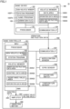
- game system 10 includes a game device 100 and a game controller 200.
- Game device 100 executes an application program such as a game program.
- Game device 100 outputs video images or images generated by execution of the application program to a not-shown display apparatus.
- Game controller 200 is an exemplary device, and it receives an operation from a user and transmits operation data showing contents of the received operation to game device 100.
- Game controller 200 includes a vibration motor 206, and has vibration motor 206 driven in accordance with an instruction from game device 100.
- FIG. 1 shows an exemplary configuration in which game system 10 includes a single game controller 200
- game system 10 may include a plurality of game controllers 200.
- Game device 100 includes a processor 101, a non-volatile memory 102, a volatile memory 103, and a communication interface (I/F) 104.
- processor 101 a non-volatile memory 102, a volatile memory 103, and a communication interface (I/F) 104.
- I/F communication interface
- Processor 101 is a processing entity that performs processing in game device 100.
- Processor 101 is processing circuitry, and it is implemented, for example, by a central processing unit (CPU) and a graphics processing unit (GPU).
- CPU central processing unit
- GPU graphics processing unit
- Processor 101 develops a program stored in non-volatile memory 102 on volatile memory 103 to execute the same.
- Processor 101 may be implemented by a system on chip (SoC) in which functions of the CPU and the GPU are integrated.
- SoC system on chip
- program herein encompasses a single program and a program group including a plurality of programs.
- Non-volatile memory 102 is a storage medium accessible by processor 101, and it is implemented, for example, by a flash memory, a read only memory (ROM), a solid state drive (SSD), and the like.
- Non-volatile memory 102 may be, for example, a storage medium attachable to and removable from game device 100, such as an optical disc and a cartridge.
- a system program 102P1 and a game program 102P2 are stored in non-volatile memory 102.
- System program 102P1 includes a computer-readable instruction for performing basic processing such as processing for communication between game device 100 and game controller 200.
- System program 102P1 may include a library necessary for execution of game program 102P2.
- Processing in game device 100 which will be described later is performed by execution of at least one of system program 102P1 and game program 102P2 by processor 101.
- Volatile memory 103 is a storage medium accessible by processor 101, and it is implemented, for example, by a dynamic random access memory (DRAM) or the like. While the game processing is being performed, volatile memory 103 includes a data area 103B1 for proceeding of a game, an operation data area 103B2, and a vibration instruction data area 103B3.
- DRAM dynamic random access memory
- Data area 103B1 is an area where data necessary for proceeding of the game is to temporarily be stored.
- Processor 101 refers to data area 103B1 while game program 102P2 is running and updates data in data area 103B1.
- Operation data area 103B2 is an area (buffer) where operation data transmitted from game controller 200 is to temporarily be stored.
- Processor 101 refers to operation data area 103B2 while game program 102P2 is running.
- Vibration instruction data area 103B3 is an area where vibration instruction data for vibration of vibration motor 206 is to temporarily be stored.
- Processor 101 writes vibration instruction data into vibration instruction data area 103B3 in predetermined cycles (for example, 60 frames per second (fps); approximately 16-msec. cycle) as game program 102P2 runs. Details of the vibration instruction data will be described later.
- memory herein encompasses at least non-volatile memory 102 and volatile memory 103.
- Communication interface 104 communicates data with game controller 200 through at least one of wireless communication and wired communication.
- communication interface 104 includes, for example, a wireless chip in conformity with Bluetooth ® standards.
- communication interface 104 includes, for example, a wired communication controller in conformity with communication standards of universal serial bus (USB).
- USB universal serial bus
- Game controller 200 includes a micro controller unit (MCU) 201 as an exemplary processor, an amplifier 205, vibration motor 206, a communication interface (I/F) 207, an acceleration sensor 208, a gyro sensor 209, an operation switch 210, and a temperature sensor 211.
- MCU micro controller unit
- I/F communication interface
- Game controller 200 is typically held with both hands or one hand of the user and receives an operation by the user as a result of operation on operation switch 210 with a user's finger.
- Game controller 200 is not limited to a game controller in such a form as being held by the user.
- a general-purpose keyboard and/or mouse including vibration motor 206 may be applicable, or the game controller may be laid on a floor and receive input based on touch of a sole of the user.
- MCU 201 includes a processor 202, a non-volatile memory 203, and a volatile memory 204.
- Processor 202 is a processing entity that performs processing in game controller 200. Processor 202 develops a program stored in non-volatile memory 203 on volatile memory 204 to execute the same. Since processor 202 is similar in hardware configuration to processor 101 described above, detailed description will not be repeated.
- Vibration instruction data area 204B1 is an area (first-in first-out (FIFO) buffer) where the vibration instruction data transmitted from game device 100 is to temporarily be stored.
- FIFO first-in first-out
- Control data area 204B2 is an area (an FIFO buffer) where the control data for vibration of vibration motor 206 generated by processor 202 is to temporarily be stored. As will be described later, in the present embodiment, the control data is generated based on the vibration instruction data.
- Operation data area 204B4 is an area (buffer) where detection values from acceleration sensor 208, gyro sensor 209, operation switch 210, and the like are to temporarily be stored. Operation data is generated based on data stored in operation data area 204B4.
- Resistance value area 204B3 is an area where a resistance value calculated based on values of a current and a voltage supplied by amplifier 205 to vibration motor 206 is to temporarily be stored.
- FIG. 1 shows an exemplary configuration in which MCU 201 including processor 202, non-volatile memory 203, and volatile memory 204 is employed, a configuration in which each element is independent may be adopted.
- Amplifier 205 supplies electric power to vibration motor 206 in accordance with control data 220.
- Amplifier 205 may supply a pulse width modulation (PWM) signal at a predetermined carrier frequency (for example, 8 kHz) to vibration motor 206.
- PWM pulse width modulation
- Control data 220 stored in control data area 204B2 in volatile memory 204 is written in amplifier 205, for example, in predetermined cycles by direct memory access (DMA).
- DMA direct memory access
- Vibration motor 206 is, for example, an eccentric motor where a weight eccentric in shape is attached to a rotation shaft. As vibration motor 206 rotates, vibration is generated. Vibration motor 206 may be a linear motor, a coin vibration motor, or the like. Vibration motor 206 can thus apply vibration to the user who holds game controller 200 where vibration motor 206 is accommodated. In game controller 200 in the present embodiment, vibration motor 206 is a voice coil motor capable of outputting audible sound.
- Acceleration sensor 208 detects magnitude of a linear acceleration along directions along predetermined three axes. Acceleration sensor 208 may detect an acceleration in a direction along one axis or directions along two axes.
- Gyro sensor 209 detects an inclination, an angular velocity, an angular acceleration, and the like of game controller 200.
- Operation switch 210 is implemented by at least one button, key, or stick provided at a surface of game controller 200.
- Operation switch 210 may typically be implemented by a button brought in correspondence with a character such as an A button and a B button, a cross-shaped key for input of upward, downward, left, and right directions, a 3D stick for input of a direction of inclination and an amount of inclination, or the like.
- Temperature sensor 211 is a sensor that measures an internal temperature of game controller 200. Temperature sensor 211 is implemented, for example, by a thermistor. Temperature sensor 211 may be arranged in the vicinity of vibration motor 206. When temperature sensor 211 is arranged at a location which is also the vicinity of the MCU, it can sense increase in temperature of both of vibration motor 206 and MCU 201.
- a not-shown one or more peripheral devices may be connectable to game controller 200.
- game controller 200 may include an interface for connection to the peripheral device.
- System program 203P includes a computer-readable instruction for performing processing necessary in game controller 200.
- System program 203P includes computer-readable instructions for performing in parallel, a plurality of types of processing such as (1) processing for generating control data 220 to be provided to amplifier 205 based on the vibration instruction data received from game device 100, (2) processing for estimating a temperature of vibration motor 206 and stopping or restricting vibration motor 206 based on the estimated temperature, (3) processing for stopping vibration motor 206 based on the temperature measured by temperature sensor 211, (4) processing for filtering detection values from acceleration sensor 208 and gyro sensor 209, (5) processing for calculating a posture based on the detection values from acceleration sensor 208 and gyro sensor 109, and (6) processing for communication between game controller 200 and game device 100.
- At least one or all of the processing (1) to the processing (6) may be computer-readable instructions independent of one another.
- system program 203P may be an assembly of software prepared for each type of processing.
- Processing for communication between game device 100 and game controller 200 includes processing for transmitting operation data including detection values from acceleration sensor 208, gyro sensor 109, operation switch 210, and the like to game device 100 and processing for receiving the vibration instruction data from game device 100.
- the vibration instruction data is data that indicates a vibration effect.
- the vibration instruction data is, for example, data that designates a waveform of the control data for control of vibration at certain timing.
- Vibration instruction data 116 includes at least one vibration parameter that indicates the waveform of the control data.
- Vibration instruction data 116 may include a set of an amplitude parameter and a frequency parameter by way of example of a vibration parameter.
- the vibration effect for a period of T ⁇ N (msec.) is designated by designation of at least one (N) piece of vibration instruction data 116 every vibration instruction cycle T (msec.) in a chronological order.
- N pieces of vibration instruction data 116 designated in the chronological order will also be referred to as a "time-series vibration instruction data group" below.
- Vibration file 105 includes information for indicating the vibration effect for each vibration event.
- time-series vibration instruction data group 110 that indicates the vibration effect corresponding to the vibration event 1 includes two pieces of vibration instruction data.
- time-series vibration instruction data group 110 includes the vibration instruction data over two vibration instruction cycles.
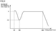
- the maximum allowable voltage can conveniently be used for each frequency to also increase an amount of vibration of vibration motor. Since time-series vibration instruction data group 110 can be generated without consideration of specifications or the like of vibration motor 206, implementation of game program 102P2 can be facilitated.
- time-series vibration instruction data group 110 (one or more pieces of vibration instruction data 112) is generated each time based on vibration file 105 is shown in the description above
- time-series vibration instruction data group 110 (one or more pieces of vibration instruction data 112) may be prepared in advance as data in a file format.
- processor 101 may read the data each time, while game program 102P2 is running. Since the necessity for processing for generating time-series vibration instruction data group 110 each time is obviated by using such data in the file format, implementation of game program 102P2 can be facilitated.
- Vibration instruction data 112 may be generated in real time without using vibration file 105.
- variation instruction data that designates variation from immediately preceding vibration may be adopted.
- the variation instruction data shows an amount of change in amplitude value and frequency, for example, as compared to the vibration parameter in an immediately preceding vibration instruction cycle.
- the vibration parameter in the present vibration instruction cycle is calculated based on the vibration parameter in the immediately preceding vibration instruction cycle and the amount of change in amplitude value and frequency.
- processing for calculating the vibration parameter may be performed by processor 101 of game device 100, the entirety or a part of the processing may be performed by MCU 201 of game controller 200.
- vibration instruction data 112 (time-series vibration instruction data group 110) including the amplitude parameter that indicates the voltage amplitude value may directly be generated by execution of the game program.
- time-series vibration instruction data group 110 (one or more pieces of vibration instruction data 112) is stored in vibration instruction data area 103B3
- a predetermined number of pieces of vibration instruction data 112 are sequentially transmitted from game device 100 to game controller 200 every cycle (for example, 5 msec.) of communication between communication interface 104 and communication interface 207.
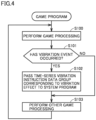
- FIG. 4 Exemplary processing by game program 102P2 in game device 100 will be described with reference to Fig. 4 .
- Each step shown in Fig. 4 is performed by execution of game program 102P2 by processor 101 of game device 100.
- game program 102P2 may be, for example, an action game, the type of the game is not limited.
- Processor 101 determines whether or not the vibration event has occurred as the game processing is performed (step S101).
- the vibration event is a trigger for application of vibration to the user, and it is, for example, an event such as collision of a game object against another game object or explosion in a virtual space.
- the vibration event may be an event that occurs at predetermined timing. The vibration event occurs when a predetermined condition is satisfied as the game proceeds.
- processor 101 passes time-series vibration instruction data group 114 corresponding to the vibration effect to system program 102P1 (step S102).
- step S102 processing in step S102 is skipped.
- Processor 101 of game device 100 executes system program 102P1 to generate time-series vibration instruction data group 114 that indicates a waveform not lower than a predetermined frequency for driving vibration motor 206 in accordance with an instruction generated by execution of an application program (game program 102P2).
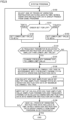
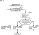
- Processor 101 selects one of pieces of vibration instruction data 116 included in time-series vibration instruction data group 114 passed from game program 102P2 (step S150). Processor 101 then determines an order that has been set for a low-pass filter (which will also be abbreviated as "LPF" below) of game controller 200 (step S151). As will be described later, the order of the LPF of game controller 200 is changeable, and an example in which the order is set to the fourth order or the sixth order will be described by way of example. The order of the LPF may be set or changed to any value.
- a low-pass filter which will also be abbreviated as "LPF” below
- processor 101 sets a lower limit value of the frequency parameter indicated in time-series vibration instruction data group 114 transmitted to game controller 200 to 40 Hz (step S152).
- processor 101 sets a lower limit value of the frequency parameter to 50 Hz (step S153).
- the lower limit value of the frequency parameter is set to be larger by a predetermined value (for example, 10 Hz) than in the example where the order of the LPF is set to the sixth order.
- a margin may be added to a certain range within which the frequency parameter is restricted.
- Processor 101 determines whether or not the frequency parameter in selected vibration instruction data 116 is equal to or smaller than the lower limit value (step S154).
- processor 101 changes the frequency parameter to the lower limit value (step S155).
- step S155 When the frequency parameter is not equal to or smaller than the lower limit value (NO in step S154), processing in step S155 is skipped.
- Processing in steps S150 to S155 is processing for restricting the lower limit value of the frequency parameter indicated in time-series vibration instruction data group 114 transmitted to game controller 200.
- Forty hertz or fifty hertz may be an exemplary lower limit frequency allowed in the control data.
- the lower limit frequency can freely be set depending on amplifier 205 and vibration motor 206 of game controller 200. Specifically, in the present embodiment, the frequency characteristics of vibration motor 206 are such that effective vibration is achieved at a frequency higher than approximately 40 Hz and vibration is quite weak when the frequency lowers, for example, to 30 Hz. Therefore, the lower limit frequency that can be used in a game application is set to 40 Hz or 50 Hz.
- step S152 the amplitude parameter may be set to 0.
- the frequency parameter in vibration instruction data 116 is not reflected on processing and hence the instruction is canceled or deactivated.
- Processing in steps S150 to S155 may be included in game program 102P2, rather than system program 102P1.
- Processor 101 determines the maximum allowable voltage in accordance with the frequency parameter in selected vibration instruction data 116 (step S156). Processor 101 calculates the voltage amplitude value by multiplying the amplitude parameter (0 to 1) in selected vibration instruction data 116 by the maximum allowable voltage (step S157). Processor 202 thus determines the amplitude value in vibration control data 220 based on change of a maximum amplitude value in accordance with the frequency in the instruction for vibration of vibration motor 206.
- Processor 101 writes a set of the calculated voltage amplitude value (amplitude parameter) and the frequency parameter in selected vibration instruction data 116 into vibration instruction data area 103B3 (step S158).
- the one or more written sets correspond to time-series vibration instruction data group 110 (vibration instruction data 112).
- Processor 101 determines whether or not it has processed all pieces of vibration instruction data 116 included in time-series vibration instruction data group 114 passed from game program 102P2 (step S159). When all pieces of vibration instruction data 116 included in time-series vibration instruction data group 114 passed from game program 102P2 have not been processed (NO in step S159), processing in step S150 or later is repeated.
- the processing shown in Fig. 5 may repeatedly be performed in predetermined cycles or may be performed by being triggered by a predetermined condition being satisfied (for example, passing of time-series vibration instruction data group 114 from game program 102P2).
- Game system 10 includes a system for estimating a temperature inside vibration motor 206 implemented by the voice coil motor.
- game controller 200 (processor 202) estimates the temperature inside vibration motor 206 based on a resistance value of vibration motor 206. More specifically, amplifier 205 obtains a current value and a voltage value of vibration motor 206 and outputs them to the MCU. Of these current value and voltage value, based on the current value and the voltage value generated by a signal corresponding to a measurement wave, the resistance value and/or the temperature are/is calculated.
- the "measurement wave” herein is a signal or a waveform for estimation of the temperature of vibration motor 206.
- the measurement wave is used for measurement of the resistance value of vibration motor 206.
- the measurement wave is typically a sinusoidal wave, it may have another waveform.
- the temperature estimated in the temperature estimation processing represents the temperature inside vibration motor 206, and it can be used, for example, for prevention of thermal degradation of vibration motor 206.
- the temperature measured by temperature sensor 211 represents the temperature outside vibration motor 206 and correlates with an internal temperature of game controller 200 and/or a surface temperature of game controller 200.
- temperature estimation system is implemented by processing on a side of game controller 200, a part or the entirety thereof may be implemented by processing on a side of game system 10.
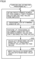
- Processor 202 calculates the resistance value based on the LPF-processed current value (the time waveform of the current values) and the LPF-processed voltage value (the time waveform of the voltage values) (step S223). Processor 202 thus calculates the resistance value inside vibration motor 206 implemented by the voice coil motor based on the current value and the voltage value subjected to the LPF processing.
- the resistance value calculated in step S223 is a value in each cycle (for example, 50 msec.) of execution of temperature estimation processing No. 1.
- Resistance value area 204B3 is configured to store forty resistance values. In this case, resistance values calculated over two seconds (50 msec. ⁇ forty) are stored in resistance value area 204B3 in a time-series manner.
- the processing shown in Fig. 8 may repeatedly be performed in predetermined execution cycles (for example, 50 msec.).
- the cycle of execution of the processing shown in Fig. 8 may be set to be longer than the cycle of execution of temperature measurement by temperature sensor 211 shown in Fig. 11 .
- load imposed on MCU 201 (processor 202) that has to perform a plurality of types of processing can be lessened while a level of temperature management is maintained.
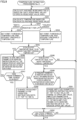
- Temperature estimation processing No. 2 in game controller 200 will be described with reference to Fig. 9 .
- Processor 202 performs temperature estimation processing No. 2 in addition to temperature estimation processing No. 1.
- Each step shown in Fig. 9 is performed by execution of system program 203P by processor 202 of game controller 200.
- Processing shown in Fig. 9 may repeatedly be performed in predetermined execution cycles (for example, 50 msec.).
- Processor 202 calculates an average resistance value of forty resistance values stored in resistance value area 204B3 (step S240). Rather than the average value, another representative value such as a median value or a mode value may be adopted. Processor 202 calculates the temperature based on the calculated average resistance value (step S241). Processing for calculating the temperature based on the average resistance value may use a predetermined calculation equation or a table in which correspondence between the resistance value and the temperature is defined. As shown in step S240, processor 202 may obtain the current value and the voltage value for a predetermined period or a predetermined number of times and may calculate the resistance value a plurality of times. Processor 202 may then estimate the temperature based on the resistance values calculated the plurality of times.
- Processor 202 determines the order that has been set for the LPF (step S242).
- processor 202 sets a first threshold temperature and a second threshold temperature in accordance with the order (sixth order) of the LPF (step S243).
- the first threshold temperature is set to be larger in value than the second threshold temperature.
- processor 202 sets the first threshold temperature and the second threshold temperature in accordance with the order (fourth order) of the LPF (step S244).
- the first threshold temperature in the case where the order of the LPF is set to the fourth order is set to be smaller in value than the first threshold temperature in the case where the order of the LPF is set to the sixth order.
- the second threshold temperature in the case where the order of the LPF is set to the fourth order is set to be smaller in value than the second threshold temperature in the case where the order of the LPF is set to the sixth order.
- Processor 202 determines whether or not the calculated temperature is equal to or higher than the first threshold temperature (step S245).
- processor 202 When the calculated temperature is equal to or higher than the first threshold temperature (YES in step S245), processor 202 changes the amplitude parameter in vibration instruction data 112 at the top among pieces of vibration instruction data 112 stored in vibration instruction data area 204B1 to zero (step S246). Processor 202 then determines whether or not a predetermined time period has elapsed (step S247). When the predetermined time period has not elapsed (NO in step S247), processing in step S246 or later is repeated. When the predetermined time period has elapsed (YES in step S247), processing in step S240 or later is repeated.
- processor 202 determines whether or not the calculated temperature is equal to or higher than the second threshold temperature (step S248). When the calculated temperature is lower than the second threshold temperature (NO in step S248), processing in step S240 or later is repeated.
- processor 202 determines whether or not the frequency parameter in vibration instruction data 112 at the top among the pieces of vibration instruction data 112 stored in vibration instruction data area 204B1 is equal to or higher than 150 Hz (step S249).
- processor 202 changes the frequency parameter in vibration instruction data 112 at the top to 100 Hz (step S250).
- processor 202 When the calculated temperature becomes equal to or larger than the predetermined value, processor 202 thus stops or restricts vibration of vibration motor 206 implemented by the voice coil motor (S246 or S250).
- processor 202 shifts the control data for vibration of vibration motor 206 implemented by the voice coil motor to a value smaller than the indicated frequency (S250). Restriction of vibration of vibration motor 206 includes processing for shifting the frequency of the waveform for driving vibration motor 206 to a frequency higher in vibration efficiency. As will be understood with reference to Fig. 3 , vibration motor 206 in the present embodiment has such characteristics as being most likely to vibrate at the frequency of 100 Hz (such characteristics as being large in vibration even at a low drive voltage).
- processor 202 decreases the amplitude parameter in vibration instruction data 112 at the top (for example, changes to a half value) (step S251).
- Processor 202 may change the amplitude parameter in vibration instruction data 112 at the top to an upper limit value only when the amplitude parameter in vibration instruction data 112 at the top exceeds the upper limit value.
- Restriction of vibration of vibration motor 206 thus includes processing for decreasing the amplitude of the waveform for driving vibration motor 206. Though both of a method of frequency shift and a method of reducing magnitude of the amplitude are thus adopted as the method of restricting vibration in the present embodiment, any one of them may be adopted.
- Processor 202 determines whether or not a predetermined time period has elapsed (step S252). When the predetermined time period has not elapsed (NO in step S252), processing in step S249 or later is repeated. When the predetermined time period has elapsed (YES in step S252), processing in step S240 or later is repeated.
- control data 220 present in control data area 240B2 may be changed to zero.
- step S247 rather than lapse of the predetermined time period, the temperature calculated by performing again step S240 and step S241 (or the temperature measured by temperature sensor 211) reaching a predetermined threshold temperature or lower may be awaited.
- vibration motor 206 When high electric power is supplied to vibration motor 206, the resistance value of vibration motor 206 instantaneously increases. Even occurrence of such instantaneous increase in resistance value less affects thermal degradation of vibration motor 206. Therefore, as shown in step S240, vibration motor 206 is stopped and/or restricted based on a result of averaging of the resistance values over a predetermined period. Output from vibration motor 206 can thus instantaneously be increased.
- step S240 accuracy in estimation of the temperature is lower as a period for estimation is shorter. Therefore, accuracy in estimation of the temperature can be improved by using an average value of the plurality of resistance values over a longer period as shown in step S240.
- Processor 202 determines whether or not load imposed on MCU 201 is equal to or higher than a predetermined level (step S2210). Whether or not load imposed on MCU 201 is equal to or higher than the predetermined level may be determined by adopting one or more of determination methods shown below.
- processor 202 sets the order of the LPF to the fourth order (step S2211). Processor 202 thus changes the order of the LPF in accordance with load imposed on MCU 201 (processor 202 that performs the LPF processing).
- processor 202 When load imposed on MCU 201 is lower than the predetermined level (NO in step S2210), processor 202 obtains the temperature estimated in step S241 (step S2212) and determines whether or not the estimated temperature is equal to or larger than the predetermined value (step S2213).
- processor 202 sets the order of the LPF to the sixth order (step S2214).
- processor 202 sets the order of the LPF to the fourth order (step S2215). Processor 202 thus changes the order of the LPF in accordance with the estimated temperature.
- the temperature estimation processing imposes large load on MCU 201. Therefore, by changing the order of the LPF that determines magnitude of load necessary for execution in accordance with load imposed on MCU 201 as shown in step S2210, influence on another type of processing to be performed by MCU 201 can be lessened.
- a processor lower in performance than the processor in the game device may be employed as the processor in the game controller. In such a case, load imposed on the processor in the game controller should be lowered.
- step S2213 When the temperature attains to a predetermined value or larger as shown in step S2213, the order of the LPF is increased to improve accuracy in estimation of the temperature. When it is not the case, on the other hand, necessity for accuracy in estimation of the temperature is low, and hence the order of the LPF is decreased to lower load necessary for processing. Thus, in a situation where accuracy in estimation of the temperature is not required, load necessary for execution is lowered so that even MCU 201 limited in processing resource can perform a plurality of types of processing in parallel.
- step S2211 the order may be decreased from the fifth order to the third order, or the order may be decreased from the sixth order to the fifth order.
- the order (the order set in S2211) when load imposed on MCU 201 is high and the order (the order set in S2215) when the estimated temperature is low may be different from each other.
- Processing in step S2211 may be performed only when the estimated temperature is lower than the predetermined value.
- the predetermined value to be used for determination as to whether or not to perform the processing in step S2211 may be set to be higher than the temperature to be used for determination in step S2213.
- accuracy in estimation of the temperature may be improved only when the temperature becomes equal to or higher than the predetermined value, and load imposed on MCU 201 may be prevented from increasing when the temperature is lower than the predetermined value.
- Processing for decreasing the order of the LPF when load imposed on MCU 201 is equal to or higher than the predetermined level or when the temperature is lower than the predetermined value may be applicable also to an example where the FIR filter is employed as the LPF.
- Change from the FIR filter to the IIR filter may be made when load imposed on MCU 201 is equal to or higher than the predetermined level. Change from the FIR filter to the IIR filter may be made when the temperature is lower than the predetermined value. At this time, the order in the calculation equation of the FIR filter may be the same as the order in the calculation equation of the IIR filter. In general, the IIR filter can achieve a greater filtering effect with the lower order (that is, lower calculation load) than the FIR filter.
- the temperature is measured with temperature sensor 211 in game controller 200.
- Vibration motor 206 may be stopped based on the measured temperature.
- FIG. 11 Exemplary processing for stopping the vibration motor based on a measured temperature in game controller 200 will be described with reference to Fig. 11 .
- Each step shown in Fig. 11 is performed by execution of system program 203P by processor 202 of game controller 200. Processing shown in Fig. 11 may repeatedly be performed in predetermined execution cycles (for example, 5 msec.).
- Processor 202 calculates the temperature based on the resistance value from temperature sensor 211 (thermistor) (step S260). Specifically, processor 202 measures the temperature with temperature sensor 211 arranged outside vibration motor 206.
- Processor 202 determines whether or not the temperature measured with temperature sensor 211 is equal to or higher than a third threshold temperature (step S261). When the measured temperature is lower than the third threshold temperature (NO in step S261), processing in step S260 or later is repeated.
- the third threshold temperature is set to be lower in value than the first threshold temperature.
- processor 202 When the calculated temperature is equal to or higher than the third threshold temperature (YES in step S261), processor 202 changes the amplitude parameter in vibration instruction data 112 at the top among the pieces of data stored in vibration instruction data area 204B1 to zero (step S262). Processor 202 then determines whether or not a predetermined time period has elapsed (step S263). When the predetermined time period has not elapsed (NO in step S263), processing in step S262 or later is repeated. When the predetermined time period has elapsed (YES in step S263), processing in step S260 or later is repeated.
- step S262 rather than changing the amplitude parameter to zero, the amplitude parameter may be reduced or the frequency parameter may be shifted as shown in steps S246 and S250 (see Fig. 9 ).
- Processor 202 thus stops or restricts vibration of vibration motor 206 implemented by the voice coil motor (S262) when the temperature measured with temperature sensor 211 becomes equal to or larger than the predetermined value.
- processor 202 stops vibration of vibration motor 206. Since the execution cycle to perform the processing shown in Fig. 11 is set, for example, to 5 msec., the cycle (5 msec.) of temperature measurement with temperature sensor 211 is shorter than the cycle (the execution cycle to perform the processing shown in Fig. 9 being set, for example, to 50 msec.) of calculation of the temperature based on the resistance value. By thus making the execution cycles different from each other, frequency to perform the temperature estimation processing which imposes great load on MCU 201 can be lowered.
- any application program can generate the vibration instruction data, without being limited to the game program.
- FIG. 1 shows an exemplary configuration in which game device 100 includes a single processor 101
- game device 100 may include a plurality of processors 101.
- MCU 201 of game controller 200 may include a plurality of processors 202.
- FIG. 1 shows an exemplary configuration in which game device 100 includes a single non-volatile memory 102 and a single volatile memory 103
- game device 100 may include a plurality of non-volatile memories 102 and/or a plurality of volatile memories 103.
- MCU 201 of game controller 200 includes a single non-volatile memory 203 and a single volatile memory 204
- MCU 201 may include a plurality of non-volatile memories 203 and/or a plurality of volatile memories 204.
- Allocation of the processing between processor 101 of game device 100 and MCU 201 (processor 202) of game controller 200 is by way of example, and processing may freely be allocated therebetween.
- the processing for generating control data 220 may be performed in game device 100.
- the program encompasses a source code, an intermediate code, an object code, a native code, a script, and the like, and a type of the code is not limited.
- the program may run on an interpreter or an emulator.
- the program may be executed by a single processor or parts of a program may be executed by different processors. Functions in the present embodiment may be performed by a plurality of divided programs, and in this case, an assembly of the plurality of programs may be defined as the program.
- the functions in the present embodiment do not have to be performed only by processing by the processor, and may be performed by using various functions of a computer (a main processor, a memory, a sub processor, a peripheral circuit, software such as firmware, and a computer implemented by an interpreter or an emulator in some cases).
- a manner in which the processor executes the program to provide an instruction to other processors, peripheral circuits, and the like and finally those other processors, peripheral circuits, and the like perform the functions is also encompassed in a mode of carrying out the present embodiment.
- a system obtained by integrating game device 100 and game controller 200 may be applicable.
- a manner in which processing performed by a single processor in the present embodiment is performed as being allocated to a plurality of processors in cooperation is also encompassed herein as a modification.
Landscapes
- Engineering & Computer Science (AREA)
- Power Engineering (AREA)
- Health & Medical Sciences (AREA)
- General Health & Medical Sciences (AREA)
- Otolaryngology (AREA)
- Physics & Mathematics (AREA)
- Acoustics & Sound (AREA)
- Signal Processing (AREA)
- Apparatuses For Generation Of Mechanical Vibrations (AREA)
Applications Claiming Priority (2)
| Application Number | Priority Date | Filing Date | Title |
|---|---|---|---|
| JP2023222062 | 2023-12-28 | ||
| JP2024184986A JP2025105449A (ja) | 2023-12-28 | 2024-10-21 | 温度推定システム、制御システム、プログラム、および、方法 |
Publications (1)
| Publication Number | Publication Date |
|---|---|
| EP4580038A1 true EP4580038A1 (de) | 2025-07-02 |
Family
ID=94284109
Family Applications (1)
| Application Number | Title | Priority Date | Filing Date |
|---|---|---|---|
| EP24222804.7A Pending EP4580038A1 (de) | 2023-12-28 | 2024-12-23 | Temperaturschätzsystem, steuerungssystem, programm und verfahren |
Country Status (2)
| Country | Link |
|---|---|
| US (1) | US20250220371A1 (de) |
| EP (1) | EP4580038A1 (de) |
Citations (3)
| Publication number | Priority date | Publication date | Assignee | Title |
|---|---|---|---|---|
| US7660067B1 (en) * | 2007-09-19 | 2010-02-09 | Western Digital Technologies, Inc. | Disk drive initializing a coil temperature estimation algorithm using a resistance of the coil estimated during a load operation |
| JP2016202486A (ja) | 2015-04-21 | 2016-12-08 | 任天堂株式会社 | 振動信号生成プログラム、振動信号生成システム、振動信号生成装置、振動信号生成方法、およびデータ出力プログラム |
| US20160360331A1 (en) * | 2015-06-05 | 2016-12-08 | Apple Inc. | Method and system for monitoring speaker temperature for speaker protection |
-
2024
- 2024-12-23 US US18/999,847 patent/US20250220371A1/en active Pending
- 2024-12-23 EP EP24222804.7A patent/EP4580038A1/de active Pending
Patent Citations (3)
| Publication number | Priority date | Publication date | Assignee | Title |
|---|---|---|---|---|
| US7660067B1 (en) * | 2007-09-19 | 2010-02-09 | Western Digital Technologies, Inc. | Disk drive initializing a coil temperature estimation algorithm using a resistance of the coil estimated during a load operation |
| JP2016202486A (ja) | 2015-04-21 | 2016-12-08 | 任天堂株式会社 | 振動信号生成プログラム、振動信号生成システム、振動信号生成装置、振動信号生成方法、およびデータ出力プログラム |
| US20160360331A1 (en) * | 2015-06-05 | 2016-12-08 | Apple Inc. | Method and system for monitoring speaker temperature for speaker protection |
Also Published As
| Publication number | Publication date |
|---|---|
| US20250220371A1 (en) | 2025-07-03 |
Similar Documents
| Publication | Publication Date | Title |
|---|---|---|
| CN102168986B (zh) | 步幅推测方法、移动轨迹计算方法及步幅推测装置 | |
| FI119619B (fi) | Kannettava elektroninen laite ja tietokoneohjelmistotuote | |
| RU2501063C2 (ru) | Устройство и способ анализа остатка для обнаружения системных ошибок в поведении системы воздушного судна | |
| JP2019072716A (ja) | ハプティック効果のための偏心回転質量アクチュエータ最適化 | |
| CN105892658B (zh) | 基于头戴显示设备预测头部姿态的方法和头戴显示设备 | |
| CN110174949A (zh) | 虚拟现实设备和姿态感知及触觉再现控制方法 | |
| EP1477370B1 (de) | Detektiergerät biologischer Informationen eines Fahrers | |
| CN205581671U (zh) | 一种智能终端的触觉振动控制系统 | |
| US8878699B2 (en) | Method for providing a pilot warning signal for a pilot of an aircraft, computer program product and warning device | |
| CN113873074A (zh) | 一种控制方法、电子设备及计算机存储介质 | |
| EP0320329A2 (de) | Leerlaufanzeige eines Echtzeitdigitalsignalprozessors | |
| EP1821071A1 (de) | Schrittzahlmessungsvorrichtung | |
| EP4580036A1 (de) | Temperaturschätzsystem, programm und temperaturschätzverfahren | |
| EP2703781A2 (de) | Elektronische Vorrichtung und Programm | |
| JP2011149923A (ja) | 歩幅推測方法、移動軌跡算出方法及び歩幅推測装置 | |
| JP5880001B2 (ja) | 覚醒度判定装置、覚醒度判定方法、及びプログラム | |
| US20250220371A1 (en) | System, non-transitory computer-readable storage medium, and method | |
| EP4580037A1 (de) | System, programm, informationsverarbeitungsverfahren und kalibrierungsverfahren | |
| US20250219568A1 (en) | Information processing method, computer system, and non-transitory computer-readable storage medium | |
| WO2014181603A1 (ja) | 歩行姿勢計およびプログラム | |
| JP2025105450A (ja) | 温度推定システム、プログラム、および温度推定方法 | |
| JP2026015709A (ja) | 温度推定システム、制御システム、プログラム、および、方法 | |
| JP2008246179A (ja) | 活動量計 | |
| CN115006824A (zh) | 一种划船机动作计数方法、装置、介质和智能穿戴设备 | |
| JP2026015699A (ja) | 情報処理システム、プログラムおよび方法 |
Legal Events
| Date | Code | Title | Description |
|---|---|---|---|
| PUAI | Public reference made under article 153(3) epc to a published international application that has entered the european phase |
Free format text: ORIGINAL CODE: 0009012 |
|
| STAA | Information on the status of an ep patent application or granted ep patent |
Free format text: STATUS: THE APPLICATION HAS BEEN PUBLISHED |
|
| AK | Designated contracting states |
Kind code of ref document: A1 Designated state(s): AL AT BE BG CH CY CZ DE DK EE ES FI FR GB GR HR HU IE IS IT LI LT LU LV MC ME MK MT NL NO PL PT RO RS SE SI SK SM TR |
|
| STAA | Information on the status of an ep patent application or granted ep patent |
Free format text: STATUS: REQUEST FOR EXAMINATION WAS MADE |
|
| 17P | Request for examination filed |
Effective date: 20251121 |