EP4580009A1 - Motor - Google Patents
Motor Download PDFInfo
- Publication number
- EP4580009A1 EP4580009A1 EP24220457.6A EP24220457A EP4580009A1 EP 4580009 A1 EP4580009 A1 EP 4580009A1 EP 24220457 A EP24220457 A EP 24220457A EP 4580009 A1 EP4580009 A1 EP 4580009A1
- Authority
- EP
- European Patent Office
- Prior art keywords
- bus bar
- motor
- coils
- neutral bus
- stator
- Prior art date
- Legal status (The legal status is an assumption and is not a legal conclusion. Google has not performed a legal analysis and makes no representation as to the accuracy of the status listed.)
- Pending
Links
Images


Classifications
-
- H—ELECTRICITY
- H02—GENERATION; CONVERSION OR DISTRIBUTION OF ELECTRIC POWER
- H02K—DYNAMO-ELECTRIC MACHINES
- H02K3/00—Details of windings
- H02K3/46—Fastening of windings on the stator or rotor structure
- H02K3/52—Fastening salient pole windings or connections thereto
- H02K3/521—Fastening salient pole windings or connections thereto applicable to stators only
- H02K3/522—Fastening salient pole windings or connections thereto applicable to stators only for generally annular cores with salient poles
-
- H—ELECTRICITY
- H02—GENERATION; CONVERSION OR DISTRIBUTION OF ELECTRIC POWER
- H02K—DYNAMO-ELECTRIC MACHINES
- H02K3/00—Details of windings
- H02K3/46—Fastening of windings on the stator or rotor structure
- H02K3/50—Fastening of winding heads, equalising connectors, or connections thereto
-
- H—ELECTRICITY
- H01—ELECTRIC ELEMENTS
- H01R—ELECTRICALLY-CONDUCTIVE CONNECTIONS; STRUCTURAL ASSOCIATIONS OF A PLURALITY OF MUTUALLY-INSULATED ELECTRICAL CONNECTING ELEMENTS; COUPLING DEVICES; CURRENT COLLECTORS
- H01R25/00—Coupling parts adapted for simultaneous co-operation with two or more identical counterparts, e.g. for distributing energy to two or more circuits
- H01R25/16—Rails or bus-bars provided with a plurality of discrete connecting locations for counterparts
- H01R25/161—Details
-
- H—ELECTRICITY
- H01—ELECTRIC ELEMENTS
- H01R—ELECTRICALLY-CONDUCTIVE CONNECTIONS; STRUCTURAL ASSOCIATIONS OF A PLURALITY OF MUTUALLY-INSULATED ELECTRICAL CONNECTING ELEMENTS; COUPLING DEVICES; CURRENT COLLECTORS
- H01R25/00—Coupling parts adapted for simultaneous co-operation with two or more identical counterparts, e.g. for distributing energy to two or more circuits
- H01R25/16—Rails or bus-bars provided with a plurality of discrete connecting locations for counterparts
- H01R25/161—Details
- H01R25/162—Electrical connections between or with rails or bus-bars
-
- H—ELECTRICITY
- H02—GENERATION; CONVERSION OR DISTRIBUTION OF ELECTRIC POWER
- H02K—DYNAMO-ELECTRIC MACHINES
- H02K13/00—Structural associations of current collectors with motors or generators, e.g. brush mounting plates or connections to windings; Disposition of current collectors in motors or generators; Arrangements for improving commutation
-
- H—ELECTRICITY
- H01—ELECTRIC ELEMENTS
- H01R—ELECTRICALLY-CONDUCTIVE CONNECTIONS; STRUCTURAL ASSOCIATIONS OF A PLURALITY OF MUTUALLY-INSULATED ELECTRICAL CONNECTING ELEMENTS; COUPLING DEVICES; CURRENT COLLECTORS
- H01R2201/00—Connectors or connections adapted for particular applications
- H01R2201/10—Connectors or connections adapted for particular applications for dynamoelectric machines
-
- H—ELECTRICITY
- H02—GENERATION; CONVERSION OR DISTRIBUTION OF ELECTRIC POWER
- H02K—DYNAMO-ELECTRIC MACHINES
- H02K2203/00—Specific aspects not provided for in the other groups of this subclass relating to the windings
- H02K2203/06—Machines characterised by the wiring leads, i.e. conducting wires for connecting the winding terminations
-
- H—ELECTRICITY
- H02—GENERATION; CONVERSION OR DISTRIBUTION OF ELECTRIC POWER
- H02K—DYNAMO-ELECTRIC MACHINES
- H02K2203/00—Specific aspects not provided for in the other groups of this subclass relating to the windings
- H02K2203/09—Machines characterised by wiring elements other than wires, e.g. bus rings, for connecting the winding terminations
Definitions
- the technology disclosed in the present specification relates to a motor.
- a three-phase alternating current motor In a three-phase alternating current motor, one end of each of three coils of U-phase, V-phase, and W-phase is connected to each other at a neutral point. The one end of the three coils is connected by a metal piece called a bus bar ( Japanese Unexamined Patent Application Publication No. 2016-127798 ( JP 2016-127798 A ), WO 2018/180798 , Japanese Unexamined Patent Application Publication No. 2021-10252 ( JP 2021-10252 A )).
- the three-phase alternating current motor will be referred to simply as a "motor”
- the bus bar that connects the ends of the three coils to each other will be referred to as a "neutral bus bar”.
- the neutral bus bar is disposed on an outer side of the coils in an axial direction of the motor.
- the present specification provides a motor in which placement of the neutral bus bar is improvised, thereby enabling the length of the motor in the axial direction to be reduced as compared to conventional motors.
- a motor disclosed in the present specification includes a plurality of coils that is wound on a stator, and a neutral bus bar connecting the coils to each other.
- a plurality of lead wires connected to the plurality of coils respectively is bent in a radial direction from an axial direction of the stator.
- the neutral bus bar is connected to a portion of a plurality of the lead wires that extends in the radial direction.
- the lead wires are bent in the radial direction, and the neutral bus bar is connected to the portions extending in the radial direction. Accordingly, the entire neutral bus bar can be brought closer to a center of the stator. This structure enables the length of the motor in the axial direction to be shortened.
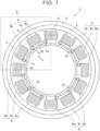
- FIG. 1 is a plan view of the motor 2 as seen from an axial direction thereof.
- FIG. 1 illustrates a state in which a cover of the motor 2 is removed.
- FIG. 2 is a perspective view of a range of a dashed-line rectangle II in FIG. 1 .
- a neutral bus bar 10 is drawn in hidden outline.
- a rotor is omitted from illustration in FIGS. 1 and 2.
- FIG. 3 is a perspective view of the neutral bus bar 10.
- FIG. 4 is a diagram of the motor 2 as viewed from a direction of arrow IV in FIG. 1
- FIG. 5 is a diagram of the motor 2 as viewed from a direction of arrow V in FIG. 1 .
- the motor 2 includes a stator 4.
- the stator 4 is accommodated in a housing 3.
- the motor 2 is an 8-pole, 12-slot three-phase alternating current motor, and the stator 4 is provided with 12 teeth 5, with a coil 6 wound around each of the teeth 5.
- Three-phase alternating current with phase difference of 120 degrees flows through each of three adjacent coils 6u, 6v, and 6w.
- the motor 2 includes four coil sets of the coils 6u, 6v, and 6w. In each coil set, alternating current with phase difference of 120 degrees flows through three adjacent coils.
- the three coils 6u, 6v, and 6w are star-coupled.
- Star coupling refers to a structure in which one of the ends of the three coils 6u, 6v, and 6w are connected to each other.
- a point of junction of the three coils 6u, 6v, and 6w is referred to as "neutral point”.
- Respective lead wires 7u, 7v, and 7w of the coils 6u, 6v, and 6w are connected to each other via the neutral bus bar 10.
- the motor 2 includes four neutral bus bars 10, and each of the neutral bus bars 10 connects three coils 6u, 6v, and 6w that are adjacent to each other.
- the neutral bus bar 10 is an elongated metal plate having a U-shaped portion 10a provided approximately at the middle thereof and L-shaped portions 10b provided at both ends thereof.
- the U-shaped portion 10a and the L-shaped portions 10b are bent portions, formed by bending the neutral bus bar 10.
- the lead wire 7v positioned at the middle is fitted into the U-shaped portion 10a of the neutral bus bar 10.
- the neutral bus bar 10 can be positioned by the U-shaped portion 10a, and accordingly clamps used when welding the lead wires 7u, 7v, 7w to the neutral bus bar 10 are not required.
- the lead wires 7u and 7w on both sides are in contact with the respective L-shaped portions 10b of the neutral bus bar 10.
- Each of the three lead wires 7u, 7v, and 7w is welded to the neutral bus bar 10, and the three coils 6u, 6v, 6w are electrically connected to each other via the neutral bus bar 10.
- the lead wires 7u, 7v, and 7w are positioned at one end of the motor 2 (stator 4) in the axial direction. Also, the lead wires 7 u, 7 v, and 7 w are positioned on an inner side of the coil 6 in a radial direction of the stator 4. The lead wires 7u, 7v, and 7w extend in the axial direction of the stator 4, and distal ends thereof are bent in the radial direction of the stator 4. The distal ends of the lead wires 7u, 7v, and 7w will be referred to as distal ends 7ue, 7ve, and 7we, respectively (see FIG. 5 ).
- distal end refers to a portion of each lead wire extending in the radial direction.
- the distal ends 7ue, 7ve, and 7we extend in the radial direction of the stator 4, and the neutral bus bar 10 is fixed to the distal ends 7ue, 7ve, and 7we.
- symbol E indicates an end of the coil 6u in the axial direction of the stator.
- the distal end 7ue of the lead wire 7u is positioned on a side closer to the center of the stator 4 in the axial direction than an end E of the coil 6u is.
- the same also applies to the lead wires 7v and 7w of the coils 6v and 6w.
- the neutral bus bar 10 connected to the distal ends 7ue, 7ve, and 7we is also positioned closer to the center of the stator 4 in the axial direction than ends E of the coils 6 are.
- the motor 2 is structured such that the neutral bus bar 10 is not positioned on an outer side of the coil 6 (on a side far from the center of the stator than the coil 6) in the axial direction, thereby enabling the length of the motor 2 in the axial direction to be shortened.
- extending portions 10c connect the U-shaped portion 10a and the L-shaped portions 10b.
- the extending portions 10c are each positioned between the distal end 7ve of the lead wire 7v at the middle and the distal ends 7ue (7we) of the lead wires 7u (7w) on the ends. According to this structure, the extending portions 10c play a role in keeping distances between the distal end 7ve and the distal ends 7ue (7we) constant.
Landscapes
- Engineering & Computer Science (AREA)
- Power Engineering (AREA)
- Insulation, Fastening Of Motor, Generator Windings (AREA)
- Windings For Motors And Generators (AREA)
Abstract
A motor (2) includes a plurality of coils (6) wound around a stator (4), and a neutral bus bar (10) connecting the plurality of coils (6) to each other. A plurality of lead wires (7u, 7v, 7w) connected to the plurality of coils (6) respectively is bent in a radial direction of the stator (4) from an axial direction of the stator (4). The neutral bus bar (10) is connected to a portion of the plurality of lead wires (7u, 7v, 7w) that extends in the radial direction.
Description
- The technology disclosed in the present specification relates to a motor.
- In a three-phase alternating current motor, one end of each of three coils of U-phase, V-phase, and W-phase is connected to each other at a neutral point. The one end of the three coils is connected by a metal piece called a bus bar (
Japanese Unexamined Patent Application Publication No. 2016-127798 JP 2016-127798 A WO 2018/180798 ,Japanese Unexamined Patent Application Publication No. 2021-10252 JP 2021-10252 A JP 2016-127798 A WO 2018/180798 , andJP 2021-10252 A - When the neutral bus bar is disposed on the outer side of the coils in the axial direction, a length of the motor in the axial direction becomes longer. The present specification provides a motor in which placement of the neutral bus bar is improvised, thereby enabling the length of the motor in the axial direction to be reduced as compared to conventional motors.
- A motor disclosed in the present specification includes a plurality of coils that is wound on a stator, and a neutral bus bar connecting the coils to each other. A plurality of lead wires connected to the plurality of coils respectively is bent in a radial direction from an axial direction of the stator. The neutral bus bar is connected to a portion of a plurality of the lead wires that extends in the radial direction. In the motor disclosed in the present specification, the lead wires are bent in the radial direction, and the neutral bus bar is connected to the portions extending in the radial direction. Accordingly, the entire neutral bus bar can be brought closer to a center of the stator. This structure enables the length of the motor in the axial direction to be shortened.
- Details and further improvements of the technology disclosed in the present specification will be described in the "DETAILED DESCRIPTION OF EMBODIMENTS" below.
- Features, advantages, and technical and industrial significance of exemplary embodiments of the invention will be described below with reference to the accompanying drawings, in which like signs denote like elements, and wherein:
-
FIG. 1 is a plan view of a motor according to an embodiment, as viewed from an axial direction; -
FIG. 2 is a perspective view of a range of a dashed-line rectangle II inFIG. 1 ; -
FIG. 3 is a perspective view of a neutral bus bar; -
FIG. 4 is a diagram of the motor as viewed from a direction of arrow IV inFIG. 1 ; and -
FIG. 5 is a diagram of the motor as viewed from a direction of arrow V inFIG. 1 . - A
motor 2 according to an embodiment will be described with reference to the drawings.FIG. 1 is a plan view of themotor 2 as seen from an axial direction thereof.FIG. 1 illustrates a state in which a cover of themotor 2 is removed.FIG. 2 is a perspective view of a range of a dashed-line rectangle II inFIG. 1 . Note however, that inFIG. 2 , aneutral bus bar 10 is drawn in hidden outline. A rotor is omitted from illustration inFIGS. 1 and2. FIG. 3 is a perspective view of theneutral bus bar 10.FIG. 4 is a diagram of themotor 2 as viewed from a direction of arrow IV inFIG. 1 , andFIG. 5 is a diagram of themotor 2 as viewed from a direction of arrow V inFIG. 1 . - The
motor 2 includes astator 4. Thestator 4 is accommodated in ahousing 3. Themotor 2 is an 8-pole, 12-slot three-phase alternating current motor, and thestator 4 is provided with 12teeth 5, with acoil 6 wound around each of theteeth 5. Three-phase alternating current with phase difference of 120 degrees flows through each of threeadjacent coils motor 2 includes four coil sets of thecoils - The three
coils coils coils Respective lead wires coils neutral bus bar 10. As illustrated inFIG. 1 , themotor 2 includes fourneutral bus bars 10, and each of theneutral bus bars 10 connects threecoils - The
neutral bus bar 10 is an elongated metal plate having aU-shaped portion 10a provided approximately at the middle thereof and L-shaped portions 10b provided at both ends thereof. The U-shapedportion 10a and the L-shaped portions 10b are bent portions, formed by bending theneutral bus bar 10. Out of thelead wires coils lead wire 7v positioned at the middle is fitted into theU-shaped portion 10a of theneutral bus bar 10. At this time, theneutral bus bar 10 can be positioned by the U-shapedportion 10a, and accordingly clamps used when welding thelead wires neutral bus bar 10 are not required. Out of the three lead wires, thelead wires portions 10b of theneutral bus bar 10. Each of the threelead wires neutral bus bar 10, and the threecoils neutral bus bar 10. - The
lead wires lead wires coil 6 in a radial direction of thestator 4. Thelead wires stator 4, and distal ends thereof are bent in the radial direction of thestator 4. The distal ends of thelead wires FIG. 5 ). Note that the term "distal end" refers to a portion of each lead wire extending in the radial direction. The distal ends 7ue, 7ve, and 7we extend in the radial direction of thestator 4, and theneutral bus bar 10 is fixed to the distal ends 7ue, 7ve, and 7we. - In
FIG. 4 , symbol E indicates an end of thecoil 6u in the axial direction of the stator. The distal end 7ue of thelead wire 7u is positioned on a side closer to the center of thestator 4 in the axial direction than an end E of thecoil 6u is. The same also applies to thelead wires coils neutral bus bar 10 connected to the distal ends 7ue, 7ve, and 7we is also positioned closer to the center of thestator 4 in the axial direction than ends E of thecoils 6 are. Themotor 2 is structured such that theneutral bus bar 10 is not positioned on an outer side of the coil 6 (on a side far from the center of the stator than the coil 6) in the axial direction, thereby enabling the length of themotor 2 in the axial direction to be shortened. - In the
neutral bus bar 10, extendingportions 10c connect the U-shapedportion 10a and the L-shaped portions 10b. The extendingportions 10c are each positioned between the distal end 7ve of thelead wire 7v at the middle and the distal ends 7ue (7we) of thelead wires 7u (7w) on the ends. According to this structure, the extendingportions 10c play a role in keeping distances between the distal end 7ve and the distal ends 7ue (7we) constant. - Some features of the
motor 2 are listed below. Themotor 2 includes a plurality of thecoils stator 4, and theneutral bus bar 10 connecting the coils to each other. Thelead wires lead wires neutral bus bar 10 is connected to portions (distal ends 7ue, 7ve, and 7we) of a plurality of thelead wires motor 2 in the axial direction to be shortened. - The
neutral bus bar 10 is positioned on a side closer to the center of thestator 4 than the ends E of thecoils 6 in the axial direction of the stator. Theneutral bus bar 10 has theU-shaped portion 10a that surrounds thelead wire 7v on three sides. Note that the U-shaped portion may be changed to a V-shaped portion that surrounds thelead wire 7v on two sides. Theneutral bus bar 10 has the L-shapedportions 10b at both ends thereof, and thelead wires portions 10b. The L-shapedportions 10b may be changed to U-shaped portions surrounding thelead wires 7u (7w) on three sides, or may be changed to I-shaped portions that come into contact with a part of thelead wire 7u (7w). - Points to be noted regarding the technology described in the embodiments will be described. The
neutral bus bar 10 is positioned on the side closer to the center of the motor than the ends E of thecoils 6 in the axial direction. In other words, theneutral bus bar 10 is positioned between both ends of thecoils 6 in the axial direction. - The
motor 2 of the embodiment includes thestator 4 with 12 slots (12 coils). The technology disclosed in present specification can also be applied to stators with three slots, six slots, and so forth. - In the drawings, only the
lead wires coils coils - The
neutral bus bar 10 is made of a metal plate. Theneutral bus bar 10 may be made of a metal rod. Thelead wires coils coil 6 in the radial direction of thestator 4. Thelead wires stator 4, and the distal ends 7ue, 7ve, and 7we thereof are bent in the radial direction of thestator 4. The distal ends 7ue, 7ve, and 7we of thelead wires stator 4. Also, thelead wires coil 6 in the radial direction of thestator 4. In this case, the distal ends 7ue, 7ve, and 7we extend toward the outer side in the radial direction of thestator 4. Theneutral bus bar 10 is disposed on the outer side of thecoil 6 in the radial direction of the stator. - The
neutral bus bar 10 may be fixed to thestator 4 with an insulator interposed therebetween. Alternatively, theneutral bus bar 10 may be fixed to thehousing 3 with an insulator interposed therebetween. - Although specific examples of the invention are described in detail above, these are only exemplary, and are not intended to limit the scope of the claims. The technology described in the claims encompasses various modifications and alterations of the specific examples exemplified above. The technical elements described in the present specification or the drawings exhibit technical utility alone or in various combinations, and are not limited to the combinations set forth in the claims as originally filed. Also, the technology exemplified in the present specification or the drawings can achieve a plurality of objects at the same time, and has technical utility in itself by achieving one of the objects.
Claims (6)
- A motor (2) comprising:a plurality of coils (6) that is wound on a stator (4); anda neutral bus bar (10) connecting the plurality of coils (6) to each other, whereina plurality of lead wires (7u, 7v, 7w) connected to the plurality of coils (6) respectively is bent in a radial direction of the stator (4) from an axial direction of the stator (4), andthe neutral bus bar (10) is connected to a portion of the plurality of the lead wires (7u, 7v, 7w) that extends in the radial direction.
- The motor (2) according to claim 1, wherein the neutral bus bar (10) is positioned, in the axial direction, on a side closer to a center of the stator (4) than an end of the plurality of coils (6).
- The motor (2) according to claim 1 or 2, wherein the neutral bus bar (10) includes at least one U-shaped portion surrounding at least one lead wire of the plurality of lead wires (7u, 7v, 7w) on three sides, or at least one V-shaped portion surrounding at least one lead wire of the plurality of lead wires (7u, 7v, 7w) on two sides.
- The motor (2) according to claim 3, wherein the at least one U-shaped portion or the at least one V-shaped portion is a bent portion fashioned by bending the neutral bus bar (10).
- The motor (2) according to claim 1, wherein the neutral bus bar (10) is connected only to a plurality of the plurality of lead wires (7u, 7v, 7w).
- The motor (2) according to claim 1, wherein the neutral bus bar (10), as viewed in the radial direction, is positioned between two ends of the plurality of coils (6) in the axial direction.
Applications Claiming Priority (1)
| Application Number | Priority Date | Filing Date | Title |
|---|---|---|---|
| JP2023222357A JP2025104507A (en) | 2023-12-28 | 2023-12-28 | Motor |
Publications (1)
| Publication Number | Publication Date |
|---|---|
| EP4580009A1 true EP4580009A1 (en) | 2025-07-02 |
Family
ID=93926632
Family Applications (1)
| Application Number | Title | Priority Date | Filing Date |
|---|---|---|---|
| EP24220457.6A Pending EP4580009A1 (en) | 2023-12-28 | 2024-12-17 | Motor |
Country Status (5)
| Country | Link |
|---|---|
| US (1) | US20250219492A1 (en) |
| EP (1) | EP4580009A1 (en) |
| JP (1) | JP2025104507A (en) |
| KR (1) | KR20250103454A (en) |
| CN (1) | CN120237843A (en) |
Citations (7)
| Publication number | Priority date | Publication date | Assignee | Title |
|---|---|---|---|---|
| JP2016127798A (en) | 2014-12-26 | 2016-07-11 | 日本電産株式会社 | Motor and motor manufacturing method |
| WO2018180798A1 (en) | 2017-03-31 | 2018-10-04 | 日本電産株式会社 | Motor and electric power steering device |
| DE102019210126A1 (en) * | 2019-07-09 | 2021-01-14 | Brose Fahrzeugteile SE & Co. Kommanditgesellschaft, Würzburg | Stator for an electric machine |
| JP2021010252A (en) | 2019-07-02 | 2021-01-28 | 日本電産株式会社 | motor |
| DE102021202034A1 (en) * | 2021-03-03 | 2022-09-08 | Thyssenkrupp Ag | Electric motor for a motor vehicle steering system and motor vehicle steering system |
| CN115051495A (en) * | 2021-03-09 | 2022-09-13 | 现代摩比斯株式会社 | Stator for motor and motor comprising same |
| WO2022208762A1 (en) * | 2021-03-31 | 2022-10-06 | 本田技研工業株式会社 | Rotating electric machine |
Family Cites Families (2)
| Publication number | Priority date | Publication date | Assignee | Title |
|---|---|---|---|---|
| JP4292050B2 (en) * | 2003-10-27 | 2009-07-08 | 本田技研工業株式会社 | Rotating electric machine stator |
| JP7468153B2 (en) * | 2020-05-28 | 2024-04-16 | 株式会社デンソー | motor |
-
2023
- 2023-12-28 JP JP2023222357A patent/JP2025104507A/en active Pending
-
2024
- 2024-12-11 CN CN202411820132.9A patent/CN120237843A/en active Pending
- 2024-12-16 KR KR1020240187039A patent/KR20250103454A/en active Pending
- 2024-12-17 EP EP24220457.6A patent/EP4580009A1/en active Pending
- 2024-12-19 US US18/987,871 patent/US20250219492A1/en active Pending
Patent Citations (7)
| Publication number | Priority date | Publication date | Assignee | Title |
|---|---|---|---|---|
| JP2016127798A (en) | 2014-12-26 | 2016-07-11 | 日本電産株式会社 | Motor and motor manufacturing method |
| WO2018180798A1 (en) | 2017-03-31 | 2018-10-04 | 日本電産株式会社 | Motor and electric power steering device |
| JP2021010252A (en) | 2019-07-02 | 2021-01-28 | 日本電産株式会社 | motor |
| DE102019210126A1 (en) * | 2019-07-09 | 2021-01-14 | Brose Fahrzeugteile SE & Co. Kommanditgesellschaft, Würzburg | Stator for an electric machine |
| DE102021202034A1 (en) * | 2021-03-03 | 2022-09-08 | Thyssenkrupp Ag | Electric motor for a motor vehicle steering system and motor vehicle steering system |
| CN115051495A (en) * | 2021-03-09 | 2022-09-13 | 现代摩比斯株式会社 | Stator for motor and motor comprising same |
| WO2022208762A1 (en) * | 2021-03-31 | 2022-10-06 | 本田技研工業株式会社 | Rotating electric machine |
Also Published As
| Publication number | Publication date |
|---|---|
| US20250219492A1 (en) | 2025-07-03 |
| CN120237843A (en) | 2025-07-01 |
| KR20250103454A (en) | 2025-07-07 |
| JP2025104507A (en) | 2025-07-10 |
Similar Documents
| Publication | Publication Date | Title |
|---|---|---|
| CN103368304B (en) | On-vehicle motor and employ the driven steering device of this on-vehicle motor | |
| CN100442640C (en) | electric motor | |
| US20060043806A1 (en) | Stator and motor | |
| CN101728888B (en) | Wiring component for motor coil | |
| JP5335265B2 (en) | Electric motor | |
| US11670979B2 (en) | Stator | |
| JP2008312290A (en) | Rotating electric machine | |
| JP6444653B2 (en) | Stator and electric pump | |
| CN114026770A (en) | Bus and motor | |
| JP6337132B2 (en) | Rotating electric machine stator and rotating electric machine equipped with the same | |
| EP4580009A1 (en) | Motor | |
| US20180115211A1 (en) | Rotary electric machine | |
| US12542461B2 (en) | Terminal block structure for stator of electric motor | |
| JP2013135547A (en) | Brushless motor and method of manufacturing the same | |
| JP2014090532A (en) | Stator of dynamo-electric machine | |
| CN218301025U (en) | Stator and motor with same | |
| CN222464279U (en) | Busbar assembly for stator and motor | |
| US20260112932A1 (en) | Balanced winding pattern with split rectangular bar wire and method | |
| JP6004708B2 (en) | Three-phase AC motor and electric compressor provided with the same | |
| JP7786293B2 (en) | Armature and rotating electric machine | |
| CN211908499U (en) | Motor stator and motor | |
| JP2024084501A (en) | Neutral conductor and rotating electrical machine | |
| CN118899980A (en) | Flat wire motor stator assembly, flat wire motor and automobile | |
| CN117914029A (en) | Motor winding, stator, motor and automobile | |
| JP2026057236A (en) | Electrical connection structure |
Legal Events
| Date | Code | Title | Description |
|---|---|---|---|
| PUAI | Public reference made under article 153(3) epc to a published international application that has entered the european phase |
Free format text: ORIGINAL CODE: 0009012 |
|
| STAA | Information on the status of an ep patent application or granted ep patent |
Free format text: STATUS: REQUEST FOR EXAMINATION WAS MADE |
|
| 17P | Request for examination filed |
Effective date: 20241217 |
|
| AK | Designated contracting states |
Kind code of ref document: A1 Designated state(s): AL AT BE BG CH CY CZ DE DK EE ES FI FR GB GR HR HU IE IS IT LI LT LU LV MC ME MK MT NL NO PL PT RO RS SE SI SK SM TR |