EP4580004A1 - Interior magnet rotor and interior magnet rotating electric machine - Google Patents
Interior magnet rotor and interior magnet rotating electric machine Download PDFInfo
- Publication number
- EP4580004A1 EP4580004A1 EP22931235.0A EP22931235A EP4580004A1 EP 4580004 A1 EP4580004 A1 EP 4580004A1 EP 22931235 A EP22931235 A EP 22931235A EP 4580004 A1 EP4580004 A1 EP 4580004A1
- Authority
- EP
- European Patent Office
- Prior art keywords
- magnet
- permanent magnet
- rotor
- housing hole
- permanent magnets
- Prior art date
- Legal status (The legal status is an assumption and is not a legal conclusion. Google has not performed a legal analysis and makes no representation as to the accuracy of the status listed.)
- Pending
Links
Images




Classifications
-
- H—ELECTRICITY
- H02—GENERATION; CONVERSION OR DISTRIBUTION OF ELECTRIC POWER
- H02K—DYNAMO-ELECTRIC MACHINES
- H02K1/00—Details of the magnetic circuit
- H02K1/06—Details of the magnetic circuit characterised by the shape, form or construction
- H02K1/22—Rotating parts of the magnetic circuit
- H02K1/27—Rotor cores with permanent magnets
- H02K1/2706—Inner rotors
- H02K1/272—Inner rotors the magnetisation axis of the magnets being perpendicular to the rotor axis
- H02K1/274—Inner rotors the magnetisation axis of the magnets being perpendicular to the rotor axis the rotor consisting of two or more circumferentially positioned magnets
- H02K1/2753—Inner rotors the magnetisation axis of the magnets being perpendicular to the rotor axis the rotor consisting of two or more circumferentially positioned magnets the rotor consisting of magnets or groups of magnets arranged with alternating polarity
- H02K1/276—Magnets embedded in the magnetic core, e.g. interior permanent magnets [IPM]
- H02K1/2766—Magnets embedded in the magnetic core, e.g. interior permanent magnets [IPM] having a flux concentration effect
-
- H—ELECTRICITY
- H02—GENERATION; CONVERSION OR DISTRIBUTION OF ELECTRIC POWER
- H02K—DYNAMO-ELECTRIC MACHINES
- H02K1/00—Details of the magnetic circuit
- H02K1/06—Details of the magnetic circuit characterised by the shape, form or construction
- H02K1/22—Rotating parts of the magnetic circuit
- H02K1/27—Rotor cores with permanent magnets
- H02K1/2706—Inner rotors
- H02K1/272—Inner rotors the magnetisation axis of the magnets being perpendicular to the rotor axis
- H02K1/274—Inner rotors the magnetisation axis of the magnets being perpendicular to the rotor axis the rotor consisting of two or more circumferentially positioned magnets
- H02K1/2753—Inner rotors the magnetisation axis of the magnets being perpendicular to the rotor axis the rotor consisting of two or more circumferentially positioned magnets the rotor consisting of magnets or groups of magnets arranged with alternating polarity
- H02K1/276—Magnets embedded in the magnetic core, e.g. interior permanent magnets [IPM]
-
- H—ELECTRICITY
- H02—GENERATION; CONVERSION OR DISTRIBUTION OF ELECTRIC POWER
- H02K—DYNAMO-ELECTRIC MACHINES
- H02K2213/00—Specific aspects, not otherwise provided for and not covered by codes H02K2201/00 - H02K2211/00
- H02K2213/03—Machines characterised by numerical values, ranges, mathematical expressions or similar information
-
- Y—GENERAL TAGGING OF NEW TECHNOLOGICAL DEVELOPMENTS; GENERAL TAGGING OF CROSS-SECTIONAL TECHNOLOGIES SPANNING OVER SEVERAL SECTIONS OF THE IPC; TECHNICAL SUBJECTS COVERED BY FORMER USPC CROSS-REFERENCE ART COLLECTIONS [XRACs] AND DIGESTS
- Y02—TECHNOLOGIES OR APPLICATIONS FOR MITIGATION OR ADAPTATION AGAINST CLIMATE CHANGE
- Y02T—CLIMATE CHANGE MITIGATION TECHNOLOGIES RELATED TO TRANSPORTATION
- Y02T10/00—Road transport of goods or passengers
- Y02T10/60—Other road transportation technologies with climate change mitigation effect
- Y02T10/64—Electric machine technologies in electromobility
Definitions
- Embodiments of the present invention relate to an interior magnet rotor and an interior magnet rotary electric machine including the same.
- each of the permanent magnets is formed in a rectangular parallelepiped shape.
- This permanent magnet is a brittle member and is likely to be chipped by an impact, and if a fragment comes off because of the chipping, the volume of the magnet reduces, leading to a decrease in the amount of magnetic flux and deterioration in properties. Further, if a fragment comes off because of chipping, the fallen fragment is caught in or clogs a gap in the synchronous machine, which causes a mechanically adverse effect such as the restriction of rotation or an electrically adverse effect such as a short circuit. Further, if chipping occurs and a fragment comes off after surface treatment is applied for rust prevention, the material is exposed, which may cause corrosion (generation of rust) from the chipped portion.
- the permanent magnet is formed in the shape having vertex portions (ridges), such as a substantially rectangular parallelepiped shape
- chamfering is performed at its four corners to remove the vertex portions and form slopes, thereby preventing chipping caused by contact between the vertex portions of magnets during the manufacture.
- a plurality of permanent magnets instead of a single permanent magnet are sometimes housed in a magnet hole of a rotor core, that is, the permanent magnet is practically divided into a plurality of pieces, whereby an eddy current generated in the permanent magnet is reduced.
- the plurality of permanent magnets are adjacent to and in contact with each other.
- the aforesaid chamfering is a work taking a lot of time and effort in the case where, for example, it is performed by barrel polishing or grinder polishing. Further, forming the slopes in advance using a die leads to an increase in the manufacturing cost.
- An object of the present invention is to provide an interior magnet rotor that achieves a reduction in a demagnetizing factor of its permanent magnet without causing an increase in an eddy current and without causing an increase in the risk of chipping of vertex portions in a plurality of permanent magnets housed in a row in a magnet housing hole.
- an interior magnet rotor includes: a rotor shaft extending in a rotation axis direction; a rotor core that has at least one magnet housing hole formed in each magnetic pole and sandwiched by a first wall and a second wall, and that is attached to the rotor shaft; and a plurality of permanent magnets housed in the magnet housing hole and arranged in a row in one direction in a cross section of the magnet housing hole, wherein the plurality of permanent magnets each have a substantially rectangular parallelepiped outer shape and have slopes formed over a longitudinal direction at two corners opposite to each other.
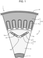
- FIG. 1 is a partial cross sectional view illustrating the structure of the interior magnet rotary electric machine 1 according to the embodiment.
- the interior magnet rotary electric machine 1 has the interior magnet rotor 10, a stator 30, and a frame 40.
- the stator 30 has a stator core 31 arranged on a radially outer side of a rotor core 12 with gap therebetween, and stator windings 32 wound around the stator core 31.
- the frame 40 houses the stator 30.
- the interior magnet rotor 10 has a rotor shaft 11, the rotor core 12 attached on the radially outer side of the rotor shaft 11, and a plurality of permanent magnets 20 housed in the rotor core 12.
- the permanent magnets 20 each have a first permanent magnet 21 and a second permanent magnet 22 arranged in series.
- FIG. 1 illustrates one magnetic pole 10a portion. Note that FIG. 1 illustrates, as an example, the case where the two permanent magnets 20 in the interior magnet rotor 10 are formed and arranged to make a pair, but this is not restrictive. For example, one of the permanent magnets 20 may form one magnetic pole.
- the feature of this embodiment relates to the plurality of permanent magnets of the permanent magnet 20 in the case where the permanent magnets 20 each have the plurality of permanent magnets arranged in series.
- the case where number of the plurality of permanent magnets that the permanent magnet 20 is two, first permanent magnet 21 and second permanent magnet 22, as illustrated in FIG. 1 will be described as an example, but they may be three permanent magnets or more.
- FIG. 2 is a perspective view illustrating the permanent magnet 20 of the interior magnet rotor 10 according to the embodiment.
- FIG. 2 illustrates a state where the first permanent magnet 21 and the second permanent magnet 22 are arranged in a row.
- the first permanent magnet 21 has a substantially rectangular parallelepiped shape.
- the first permanent magnet 21 has four side faces, namely, a first side face 21a, a second side face 21b, a third side face 21c, and a fourth side face 21d each located along the longitudinal direction, that is, the axial direction of the rotor shaft 11.
- a first corner slope 21p is formed on a corner where the first side face 21a and the second side face 21b connect with each other.
- a second corner slope 21q is formed on a corner where the third side face 21c and the fourth side face 21d connect with each other.
- the first corner slope 21p makes a 45-degree angle with the first side face 21a and the second side face 21b.
- the second corner slope 21q makes a 45-degree angle with the third side face 21c and the fourth side face 21d.
- the first permanent magnet 21 and the second permanent magnet 22 are arranged with the first side face 21a of the first permanent magnet 21 and the first side face 22a of the second permanent magnet 22 facing the same direction, and with the second side face 21b of the first permanent magnet 21 and the third side face 22c of the second permanent magnet 22 facing and adjacent to each other. In other words, the first permanent magnet 21 and the second permanent magnet 22 are arranged in the same orientation.
- first corner slope 21p and the second corner slope 21q of the first permanent magnet 21 and the first corner slope 22p and the second corner slope 22q of the second permanent magnet 22 are each adjacent to any of the side faces. That is, corners not having the first corner slope 21p nor the second corner slope 21q of the first permanent magnet 21 and corners not having the first corner slope 22p nor the second corner slope 22q of the second permanent magnet 22 are not adjacent to each other.
Landscapes
- Engineering & Computer Science (AREA)
- Power Engineering (AREA)
- Permanent Field Magnets Of Synchronous Machinery (AREA)
Abstract
Description
- Embodiments of the present invention relate to an interior magnet rotor and an interior magnet rotary electric machine including the same.
- In a synchronous machine such as an interior magnet synchronous motor whose rotor has permanent magnets, each of the permanent magnets is formed in a rectangular parallelepiped shape. This permanent magnet is a brittle member and is likely to be chipped by an impact, and if a fragment comes off because of the chipping, the volume of the magnet reduces, leading to a decrease in the amount of magnetic flux and deterioration in properties. Further, if a fragment comes off because of chipping, the fallen fragment is caught in or clogs a gap in the synchronous machine, which causes a mechanically adverse effect such as the restriction of rotation or an electrically adverse effect such as a short circuit. Further, if chipping occurs and a fragment comes off after surface treatment is applied for rust prevention, the material is exposed, which may cause corrosion (generation of rust) from the chipped portion.
- Because of these reasons, in the case where the permanent magnet is formed in the shape having vertex portions (ridges), such as a substantially rectangular parallelepiped shape, after it is worked into this shape, chamfering is performed at its four corners to remove the vertex portions and form slopes, thereby preventing chipping caused by contact between the vertex portions of magnets during the manufacture.
- Further, in recent years, to improve the efficiency of a rotary electric machine, a plurality of permanent magnets instead of a single permanent magnet are sometimes housed in a magnet hole of a rotor core, that is, the permanent magnet is practically divided into a plurality of pieces, whereby an eddy current generated in the permanent magnet is reduced. As a result, in the state of a product, the plurality of permanent magnets are adjacent to and in contact with each other.
-
- Patent Document 1:
Japanese Patent No. 5776275 - Patent Document 2: International Publication No.
2014/030547 - The aforesaid chamfering is a work taking a lot of time and effort in the case where, for example, it is performed by barrel polishing or grinder polishing. Further, forming the slopes in advance using a die leads to an increase in the manufacturing cost.
- Further, to form the slopes by removing the vertex portions as described above is, in other words, to previously reduce magnetic force by changing the rectangular parallelepiped shape of the magnet to a chipped state, and is a work without any electromagnetic merit. Further, it is necessary to note that dividing the magnet inserted in the rotor into the plurality of pieces increases the frequency with which the corners of the magnets come into contact with each other in the manufacturing process.
- An object of the present invention is to provide an interior magnet rotor that achieves a reduction in a demagnetizing factor of its permanent magnet without causing an increase in an eddy current and without causing an increase in the risk of chipping of vertex portions in a plurality of permanent magnets housed in a row in a magnet housing hole.
- To attain the above object, an interior magnet rotor according to an embodiment of the present invention includes: a rotor shaft extending in a rotation axis direction; a rotor core that has at least one magnet housing hole formed in each magnetic pole and sandwiched by a first wall and a second wall, and that is attached to the rotor shaft; and a plurality of permanent magnets housed in the magnet housing hole and arranged in a row in one direction in a cross section of the magnet housing hole, wherein the plurality of permanent magnets each have a substantially rectangular parallelepiped outer shape and have slopes formed over a longitudinal direction at two corners opposite to each other.
-
-
FIG. 1 is a partial cross sectional view illustrating the structure of an interior magnet rotary electric machine according to an embodiment. -
FIG. 2 is a perspective view illustrating a permanent magnet of an interior magnet rotor according to the embodiment. -
FIG. 3 is a partial cross sectional view illustrating the permanent magnet and a rotor core of the interior magnet rotor according to the embodiment. -
FIG. 4 is a partial cross sectional view illustrating a region around a first permanent magnet of the interior magnet rotor according to the embodiment. -
FIG. 5 is a partial cross sectional view illustrating a region around a second permanent magnet of the interior magnet rotor according to the embodiment. -
FIG. 6 is a partial cross sectional view illustrating a conventional example of a permanent magnet of an interior magnet rotor and illustrating the permanent magnet and a rotor core. -
FIG. 7 is a graph illustrating an example of the comparison of a demagnetizing factor to explain the effect of the interior magnet rotor according to the embodiment. -
FIG. 8 is a graph illustrating an example of the comparison of torque-current characteristics to explain the effect of the interior magnet rotor according to the embodiment. - An interior magnet rotor and an interior magnet rotary electric machine according to an embodiment of the present invention will be hereinafter described with reference to the drawings. Here, parts that are identical or similar to each other will be denoted by common reference signs and a redundant description thereof will be omitted.
-
FIG. 1 is a partial cross sectional view illustrating the structure of the interior magnet rotaryelectric machine 1 according to the embodiment. - The interior magnet rotary
electric machine 1 has theinterior magnet rotor 10, astator 30, and aframe 40. Thestator 30 has astator core 31 arranged on a radially outer side of arotor core 12 with gap therebetween, andstator windings 32 wound around thestator core 31. Theframe 40 houses thestator 30. - The
interior magnet rotor 10 has arotor shaft 11, therotor core 12 attached on the radially outer side of therotor shaft 11, and a plurality ofpermanent magnets 20 housed in therotor core 12. - The
permanent magnets 20 each have a firstpermanent magnet 21 and a secondpermanent magnet 22 arranged in series. -
FIG. 1 illustrates onemagnetic pole 10a portion. Note thatFIG. 1 illustrates, as an example, the case where the twopermanent magnets 20 in theinterior magnet rotor 10 are formed and arranged to make a pair, but this is not restrictive. For example, one of thepermanent magnets 20 may form one magnetic pole. - The feature of this embodiment relates to the plurality of permanent magnets of the
permanent magnet 20 in the case where thepermanent magnets 20 each have the plurality of permanent magnets arranged in series. In the following, the case where number of the plurality of permanent magnets that thepermanent magnet 20 is two, firstpermanent magnet 21 and secondpermanent magnet 22, as illustrated inFIG. 1 will be described as an example, but they may be three permanent magnets or more. -
FIG. 2 is a perspective view illustrating thepermanent magnet 20 of theinterior magnet rotor 10 according to the embodiment.FIG. 2 illustrates a state where the firstpermanent magnet 21 and the secondpermanent magnet 22 are arranged in a row. - The first
permanent magnet 21 has a substantially rectangular parallelepiped shape. The firstpermanent magnet 21 has four side faces, namely, afirst side face 21a, asecond side face 21b, athird side face 21c, and afourth side face 21d each located along the longitudinal direction, that is, the axial direction of therotor shaft 11. On a corner where the first side face 21a and thesecond side face 21b connect with each other, afirst corner slope 21p is formed. Further, on a corner where the third side face 21c and thefourth side face 21d connect with each other, a second corner slope 21q is formed. Thefirst corner slope 21p makes a 45-degree angle with thefirst side face 21a and thesecond side face 21b. Similarly, the second corner slope 21q makes a 45-degree angle with thethird side face 21c and thefourth side face 21d. - Similarly, the second
permanent magnet 22 also has a substantially rectangular parallelepiped shape and has four side faces, namely, afirst side face 22a, asecond side face 22b, athird side face 22c, and afourth side face 22d along the longitudinal direction, that is, the axial direction of therotor shaft 11. On a corner where the first side face 22a and thesecond side face 22b connect with each other, afirst corner slope 22p is formed. Further, on a corner where the third side face 22c and thefourth side face 22d connect with each other, a second corner slope 22q is formed. Thefirst corner slope 22p makes a 45-degree angle with thefirst side face 22a and thesecond side face 22b. Similarly, the second corner slope 22q makes a 45-degree angle with thethird side face 22c and thefourth side face 22d. - It should be noted that this angle is not limited to 45 degrees and may be 60 degrees with respect to one of the side faces, for instance. The angles of the
first corner slope 21p and the second corner slope 21q may be different. Further, the areas of thefirst corner slope 21p and the second corner slope 21q may be different. In the following, the case where their angles are both 45 degrees and their areas are equal will be described as an example. - The first
permanent magnet 21 and the secondpermanent magnet 22 are arranged with thefirst side face 21a of the firstpermanent magnet 21 and thefirst side face 22a of the secondpermanent magnet 22 facing the same direction, and with thesecond side face 21b of the firstpermanent magnet 21 and thethird side face 22c of the secondpermanent magnet 22 facing and adjacent to each other. In other words, the firstpermanent magnet 21 and the secondpermanent magnet 22 are arranged in the same orientation. - Therefore, the
first corner slope 21p and the second corner slope 21q of the firstpermanent magnet 21 and thefirst corner slope 22p and the second corner slope 22q of the secondpermanent magnet 22 are each adjacent to any of the side faces. That is, corners not having thefirst corner slope 21p nor the second corner slope 21q of the firstpermanent magnet 21 and corners not having thefirst corner slope 22p nor the second corner slope 22q of the secondpermanent magnet 22 are not adjacent to each other. - It is possible to form the corner slopes by chamfering the corners of the rectangular parallelepiped
permanent magnet 20 by barrel polishing or grinder polishing, for instance. Alternatively, it is possible to form them by shaping the permanent magnet into the form having the corner slopes before sintering. -
FIG. 3 is a partial cross sectional view illustrating thepermanent magnet 20 and therotor core 12 of theinterior magnet rotor 10 according to the embodiment.FIG. 3 illustrates only one of the twopermanent magnets 20 forming the singlemagnetic pole 10a illustrated inFIG. 1 . - The
magnet housing hole 12a of therotor core 12 has anouter positioning projection 12c formed on the radially outer side of a radiallyinner side face 12d of themagnet housing hole 12a, and theouter positioning projection 12c is a stepped portion toward the radially inner side. Further, aninner positioning projection 12b is formed on the radially inner side of a radiallyouter side face 12e of themagnet housing hole 12a and is a stepped portion toward the radially outer side. - In the
magnet housing hole 12a, thepermanent magnet 20 is housed and fixed in a region sandwiched by theinner positioning projection 12b and theouter positioning projection 12c. Specifically, as thepermanent magnet 20, the firstpermanent magnet 21 is arranged on the radially inner side, and the secondpermanent magnet 22 is arranged on the radially outer side adjacently to the firstpermanent magnet 21. - The first
permanent magnet 21 is arranged with itsfirst side face 21a facing the radiallyouter side face 12e of themagnet housing hole 12a, itssecond side face 21b facing the secondpermanent magnet 22, itsthird side face 21c facing the radiallyinner side face 12d of themagnet housing hole 12a, and itsfourth side face 21d partly facing theinner positioning projection 12b. - Further, the second
permanent magnet 22 is arranged with itsfirst side face 22a facing the radiallyouter side face 12e of themagnet housing hole 12a, itssecond side face 22b partly facing theouter positioning projection 12c, itsthird side face 22c facing the radiallyinner side face 12d of themagnet housing hole 12a, and itsfourth side face 22d facing the firstpermanent magnet 21. - Here, the thickness of the first
permanent magnet 21 and the secondpermanent magnet 22 is referred to as "d". Further, the width of thefirst corner slope 21p of the firstpermanent magnet 21 in a view of the firstpermanent magnet 21 seen from the secondpermanent magnet 22 side is referred to as "w1". Further, the width of the second corner slope 22q of the secondpermanent magnet 22 in a view of the secondpermanent magnet 22 seen from the firstpermanent magnet 21 side is referred to as "w2". - Because of such an arrangement of the first
permanent magnet 21 and the secondpermanent magnet 22, the width of a contact surface between the firstpermanent magnet 21 and the secondpermanent magnet 22 is [d - (w1 + w2)]. -
FIG. 4 is a partial cross sectional view illustrating a region around the firstpermanent magnet 21 of theinterior magnet rotor 10 according to the embodiment. - In the
magnet housing hole 12a formed in theinterior magnet rotor 10, themagnet housing hole 12a itself and thepermanent magnet 20 housed in themagnet housing hole 12a have a high magnetic reluctance against an external magnetic field and function as a flux barrier. The width of the flux barrier is mostly equal to the distance d0 between the radiallyinner side face 12d and the radiallyouter side face 12e of themagnet housing hole 12a. - Around the first
permanent magnet 21, the smallest width of the flux barrier is the distance d1 between point P1 and point P2 in the cross section shown inFIG. 4 . Here, point P1 is the vertex portion of theinner positioning projection 12b. Further, point P2 is the radially innermost portion of thethird side face 21c of the firstpermanent magnet 21. For a magnetic flux to pass between point P1 and point P2 with the shortest distance, it needs to pass the inside of the firstpermanent magnet 21. -
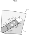
FIG. 5 is a partial cross sectional view illustrating a region around the secondpermanent magnet 22 of theinterior magnet rotor 10 according to the embodiment. - Around the second
permanent magnet 22, the smallest width of the flux barrier is the distance d2 between point P3 and point P4 in the cross section inFIG. 5 . Here, point P3 is the radially outermost portion of thefirst side face 22a of the secondpermanent magnet 22. Further, point P4 is the vertex portion of theouter positioning projection 12c. For a magnetic flux to pass between point P3 and point P4 with the shortest distance, it needs to pass the inside of the secondpermanent magnet 22. -
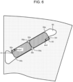
FIG. 6 is a partial cross sectional view illustrating a conventional example of a permanent magnet of an interior magnet rotor and illustrating the permanent magnet and a rotor core.FIG. 6 illustrates the conventional example as a comparative example with the present embodiment. - In the comparative example, two conventional permanent magnets 50 are arranged in line in the radial direction. The conventional permanent magnets 50 are different from those of this embodiment in that they each have slopes at four places, namely, they each have a
first corner slope 50p, asecond corner slope 50r, a third corner slope 50q, and afourth corner slope 50s. - For comparison, the distance between two faces in the conventional permanent magnets 50 is equal to that in the first
permanent magnet 21 and the secondpermanent magnet 22 of this embodiment. That is, the dimensions of their rectangular parallelepiped shapes are equal if the slopes are disregarded. Further, it is assumed that their slopes also have the same size. What is different is that the slopes which are portions corresponding to lacking from the rectangular parallelepiped shape are formed at the two corners opposite to each other in this embodiment while, in the comparative example, they are formed at four places which are all the corners. - Therefore, the shape of a
magnet housing hole 60 housing the two conventional permanent magnets 50 is substantially the same as the shape of themagnet housing hole 12a in this embodiment. What is different is only that the dimension of anouter positioning projection 61 and aninner positioning projection 62 of themagnet housing hole 60 of the comparative example is different from the dimension of theinner positioning projection 12b and theouter positioning projection 12c of themagnet housing hole 12a of this embodiment. - Specifically, in the comparative example, to hold the conventional permanent magnet 50 on whose radially inner side the
inner positioning projection 61 is arranged, the tip of theinner positioning projection 61 needs to extend into themagnet housing hole 60 so that it does not end in the middle of thefourth corner slope 50s formed in the conventional permanent magnet 50. - Here, a component along the extension direction of the
inner positioning projection 61, of the width of thefourth corner slope 50s is referred to as "Δw1". If the same width as the width with which theinner positioning projection 12b of this embodiment holds the firstpermanent magnet 21 is tried to be obtained, the shortest distance reduces approximately to be (d1 - Δw1) in the comparative example. - Similarly, in the comparative example, in order to hold the conventional permanent magnet 50 on whose radially outer side the
outer positioning projection 62 is arranged, the tip of theouter positioning projection 62 needs to extend into themagnet housing hole 60 so that this tip does not end in the middle of thesecond corner slope 50r formed in the conventional permanent magnet 50. - Here, a component along the extension direction of the
outer positioning projection 62, of the width of thesecond corner slope 50r is referred to as "Δw2". If the same width as the width with which theouter positioning projection 12c of this embodiment holds the secondpermanent magnet 22 is tried to be obtained, the shortest distance reduces approximately to be (d2 - Δw2). - From the above, in this embodiment, as compared with the comparative example, it is possible to make the height of the
inner positioning projection 12b and theouter positioning projection 12c shorter, and as a result, a magnetic reluctance at the time of the application of a demagnetizing field increases, making it possible to improve demagnetization resistance. -
FIG. 7 is a graph illustrating an example of the comparison of a demagnetizing factor to explain the effect of theinterior magnet rotor 10 according to the embodiment. The horizontal axis represents cases, which are a case where the permanent magnet is thin and a case where it is thick. Further, regarding each of these cases, the case of the comparative example is illustrated with a gray bar, and the case of present embodiment is illustrated with a void bard. The vertical axis represents the demagnetizing factor [P.U.] and represents a relative value to a reference value in the comparative example. - As illustrated in
FIG. 7 , in the case where the permanent magnet is thin, the demagnetizing factor [P.U.] in the present embodiment is lower than that in the comparative example by 33%. Further, in the case where the permanent magnet is thick, the demagnetizing factor [P.U.] in the present embodiment is lower than that in the comparative example by 9%. - As described above, in the present embodiment, especially owing to the shorter height of the
inner positioning projection 12b and theouter positioning projection 12c, the width of the portion where the width of the flux barrier is smallest increases, which makes it possible to increase a magnetic reluctance at the time of the application of a demagnetizing field and improve demagnetization resistance. -
FIG. 8 is a graph illustrating an example of the comparison of the torque-current characteristics to explain the effect of theinterior magnet rotor 10 according to the present embodiment. The horizontal axis represents a relative value of torque. The vertical axis represents an armature current flowing in the stator winding 32, which is necessary to generate the torque, and represents a relative value to a reference value in the comparative example. The void circles indicate the case of the comparative example and the black squares indicate the case of the present embodiment. - In the
permanent magnet 20 in the present embodiment, the number of the portions corresponding to lacking from the rectangular parallelepiped shape due to the formation of the slopes is half of that in the comparative example. Accordingly, a reduction in magnetic force in thepermanent magnet 20 from the rectangular parallelepiped shape is smaller than that in the comparative example. As a result, as illustrated inFIG 8 , it is possible to reduce the armature current by about 0.6% or more. That is, a larger torque can be obtained with the same value of the armature current. - As described above, while the conventional permanent magnet 50 in the comparative example has four slopes, the
permanent magnet 20 in the present embodiment has the slopes respectively formed at the two places opposite to each other so that the number of the portions corresponding to lacking from the rectangular parallelepiped shape is half of that in the comparative example. Moreover, it is possible to increase the width of the portion, in themagnet housing hole 12a, where the width of the flux barrier is smallest. Note that the contact area between the firstpermanent magnet 21 and the secondpermanent magnet 22 adjacent to each other is the same as that in the comparative example. - As a result, it is possible to reduce the demagnetizing factor of the
permanent magnet 20 and improve the torque-current characteristics. - Further, according to the present embodiment, the contact width of the
permanent magnets 20 adjacent to each other, which is an index influencing the level of an eddy current, is the same as that in the comparative example. Further, regarding thepermanent magnets 20 adjacent to each other, the corners with no slopes in one of thepermanent magnets 20 are adjacent to the slopes in the adjacentpermanent magnet 20, and thus the corners with no slopes are not adjacent to each other. As a result, the same effect as that of the comparative example is exhibited in terms of the prevention of the chipping of the corners. - Moreover, since the number of the slopes is reduced to half, the number of production processes can be reduced in the case, for example, wherein the slopes are formed by barrel polishing or grinder polishing.
- According to the embodiment described hitherto, it is possible to provide an interior magnet rotor that achieves a reduction in a demagnetizing factor of its permanent magnet without causing an increase in an eddy current and without causing an increase in the risk of chipping of vertex portions in a plurality of permanent magnets housed in a row in a magnet housing hole.
- While certain embodiments have been described, these embodiments have been presented by way of example only, and are not intended to limit the scope of the inventions. Further, the features of the embodiments may be combined. Further, the embodiments may be embodied in a variety of other forms; furthermore, various omissions, substitutions and changes in the form of the embodiments described herein may be made without departing from the spirit of the inventions. The accompanying claims and their equivalents are intended to cover such forms or modifications as would fall within the scope and spirit of the inventions.
- 1...interior magnet rotary electric machine, 10...interior magnet rotor, 10a...magnetic pole, 11...rotor shaft, 12... rotor core, 12a...magnet housing hole, 12b...inner positioning projection, 12c...outer positioning projection, 12d...radially inner side face, 12e...radially outer side face, 20...permanent magnet, 21...first permanent magnet, 21a...first side face, 21b...second side face, 21c...third side face, 21d...fourth side face, 21p...first corner slope, 21q...second corner slope, 22...second permanent magnet, 22a...first side face, 22b...second side face, 22c...third side face, 22d...fourth side face, 22p...first corner slope, 22q...second corner slope, 30...stator, 31...stator core, 32...stator winding, 40...frame, 50...conventional permanent magnet, 50p...first corner slope, 50r...second corner slope, 50q...third corner slope, 50s...fourth corner slope, 60...magnet housing hole, 61...inner positioning projection, 62...outer positioning projection
Claims (4)
- An interior magnet rotor comprising:a rotor shaft extending in a rotation axis direction;a rotor core that has at least one magnet housing hole formed in each magnetic pole and sandwiched by a first wall and a second wall, and that is attached to the rotor shaft; anda plurality of permanent magnets housed in the magnet housing hole and arranged in a row in one direction in a cross section of the magnet housing hole,wherein the plurality of permanent magnets each have a substantially rectangular parallelepiped outer shape and have slopes formed over a longitudinal direction on two corners opposite to each other.
- The interior magnet rotor according to claim 1, wherein the plurality of permanent magnets are arranged in a row with the slopes being in the same orientation.
- The interior magnet rotor according to claim 1,wherein the first wall and the second wall of the magnet housing hole respectively have a first holding projection and a second holding projection that project to the magnet housing hole to hold the plurality of permanent magnets, andwherein in the permanent magnets, facing portions facing the first holding projection and the second holding projection respectively are corners where the slopes are not formed.
- An interior magnet rotary electric machine comprising:the interior magnet rotor according to any one of claim 1 to claim 3; anda stator having a stator core and stator windings wound around the stator core.
Applications Claiming Priority (2)
| Application Number | Priority Date | Filing Date | Title |
|---|---|---|---|
| JP2022134141 | 2022-08-25 | ||
| PCT/JP2022/038530 WO2024042731A1 (en) | 2022-08-25 | 2022-10-17 | Interior magnet rotor and interior magnet rotating electric machine |
Publications (2)
| Publication Number | Publication Date |
|---|---|
| EP4580004A1 true EP4580004A1 (en) | 2025-07-02 |
| EP4580004A4 EP4580004A4 (en) | 2026-04-01 |
Family
ID=88021751
Family Applications (1)
| Application Number | Title | Priority Date | Filing Date |
|---|---|---|---|
| EP22931235.0A Pending EP4580004A4 (en) | 2022-08-25 | 2022-10-17 | INTERNAL MAGNET ROTOR AND ELECTRIC INTERNAL MAGNET LATHE |
Country Status (4)
| Country | Link |
|---|---|
| US (1) | US20240072583A1 (en) |
| EP (1) | EP4580004A4 (en) |
| JP (1) | JP7346771B1 (en) |
| CN (1) | CN117941222A (en) |
Families Citing this family (2)
| Publication number | Priority date | Publication date | Assignee | Title |
|---|---|---|---|---|
| CN121058149A (en) * | 2024-04-02 | 2025-12-02 | 烟台东星磁性材料股份有限公司 | Rotor with permanent magnets of irregular polyhedral shape |
| DE102024119407A1 (en) * | 2024-07-09 | 2026-01-15 | Dr. Ing. H.C. F. Porsche Aktiengesellschaft | Mounting bracket and rotor lamination section of an electric motor |
Family Cites Families (15)
| Publication number | Priority date | Publication date | Assignee | Title |
|---|---|---|---|---|
| CN102171909B (en) * | 2008-11-19 | 2013-08-28 | 三菱电机株式会社 | Rotor of motor and motor and fan and compressor |
| JP5328821B2 (en) * | 2011-02-03 | 2013-10-30 | トヨタ自動車株式会社 | Rotating machine rotor |
| KR101566047B1 (en) * | 2011-03-29 | 2015-11-05 | 한양대학교 산학협력단 | Spoke type permanent magnet motor |
| JP5776275B2 (en) * | 2011-03-31 | 2015-09-09 | Tdk株式会社 | Composite magnet structure |
| JP5936060B2 (en) * | 2012-09-14 | 2016-06-15 | 株式会社デンソー | Rotating electrical machine rotor |
| JP6110151B2 (en) * | 2013-02-07 | 2017-04-05 | 本田技研工業株式会社 | Rotating electrical machine rotor |
| JP5930994B2 (en) * | 2013-03-22 | 2016-06-08 | 三菱電機株式会社 | Rotor, compressor and refrigeration air conditioner for embedded permanent magnet electric motor |
| JP6079887B2 (en) * | 2013-08-29 | 2017-02-15 | 日産自動車株式会社 | Cleaving method and cleaving apparatus for manufacturing a magnet piece constituting a field pole magnet body disposed in a rotating electrical machine |
| JP5962632B2 (en) * | 2013-11-15 | 2016-08-03 | 株式会社デンソー | Rotor for rotating electrical machine and method for manufacturing the same |
| JP2018164378A (en) * | 2017-03-27 | 2018-10-18 | 本田技研工業株式会社 | Magnet for IPM rotor, IPM rotor and method for manufacturing magnet for IPM rotor |
| JP6828724B2 (en) * | 2017-08-01 | 2021-02-10 | 株式会社デンソー | Magnet manufacturing method and magnetizing device |
| JP6852694B2 (en) * | 2017-08-01 | 2021-03-31 | 株式会社デンソー | Magnetic generator of electric motor |
| DE112018006694T5 (en) * | 2017-12-28 | 2020-09-10 | Denso Corporation | Rotating electric machine |
| JP7594349B2 (en) * | 2018-11-15 | 2024-12-04 | 株式会社デンソー | Rotating Electric Machine |
| JP7371361B2 (en) * | 2019-06-20 | 2023-10-31 | 株式会社デンソー | rotating electric machine |
-
2022
- 2022-10-17 JP JP2023520295A patent/JP7346771B1/en active Active
- 2022-10-17 EP EP22931235.0A patent/EP4580004A4/en active Pending
- 2022-10-17 CN CN202280009180.2A patent/CN117941222A/en active Pending
-
2023
- 2023-09-25 US US18/473,481 patent/US20240072583A1/en active Pending
Also Published As
| Publication number | Publication date |
|---|---|
| JP7346771B1 (en) | 2023-09-19 |
| JPWO2024042731A1 (en) | 2024-02-29 |
| CN117941222A (en) | 2024-04-26 |
| US20240072583A1 (en) | 2024-02-29 |
| EP4580004A4 (en) | 2026-04-01 |
Similar Documents
| Publication | Publication Date | Title |
|---|---|---|
| US7342338B2 (en) | Permanent magnet electric motor with reduced cogging torque | |
| US7042127B2 (en) | Permanent magnet embedded motor | |
| CN106165259B (en) | Permanent magnet submerged type electric rotating machine | |
| JP5537964B2 (en) | Rotating electric machine | |
| US6717315B1 (en) | Permanent magnet type motor and method of producing permanent magnet type motor | |
| CN101461119B (en) | Split type iron core and its manufacturing method, and stator iron core | |
| JP6461381B2 (en) | Rotating electric machine stator, rotating electric machine, and method of manufacturing rotating electric machine stator | |
| US20120267975A1 (en) | Embedded permanent magnet electric motor | |
| US20240072583A1 (en) | Interior magnet rotor and interior magnet rotary electric machine | |
| JP5040988B2 (en) | Stator and motor provided with the stator | |
| JPWO2017090571A1 (en) | Motor and motor manufacturing method | |
| CN102754307A (en) | Permanent magnet, motor rotor or stator, dynamo-electric machine | |
| JP5313935B2 (en) | Manufacturing method of stator of rotating electric machine and stator of rotating electric machine | |
| US20130342065A1 (en) | Brushless motor and method for manufacturing brushless motor | |
| CN108496293B (en) | Electrical sheet with printed connecting sheet | |
| US11228226B2 (en) | Electric machine comprising a knurled rotor shaft and method of manufacturing such a machine | |
| KR100624381B1 (en) | Rotor of permanent magnet embedded motor and its manufacturing method | |
| US12388315B2 (en) | Electric rotating machine | |
| JP2003061319A (en) | Stator manufacturing method | |
| WO2024042731A1 (en) | Interior magnet rotor and interior magnet rotating electric machine | |
| US12176760B2 (en) | Interior permanent magnet motor | |
| EP4300773A1 (en) | Stator and brushless motor | |
| CN118575392A (en) | Stator and motor | |
| US20110121679A1 (en) | Motor | |
| JP6900790B2 (en) | Rotating machine |
Legal Events
| Date | Code | Title | Description |
|---|---|---|---|
| STAA | Information on the status of an ep patent application or granted ep patent |
Free format text: STATUS: UNKNOWN |
|
| STAA | Information on the status of an ep patent application or granted ep patent |
Free format text: STATUS: THE INTERNATIONAL PUBLICATION HAS BEEN MADE |
|
| PUAI | Public reference made under article 153(3) epc to a published international application that has entered the european phase |
Free format text: ORIGINAL CODE: 0009012 |
|
| STAA | Information on the status of an ep patent application or granted ep patent |
Free format text: STATUS: REQUEST FOR EXAMINATION WAS MADE |
|
| 17P | Request for examination filed |
Effective date: 20230920 |
|
| AK | Designated contracting states |
Kind code of ref document: A1 Designated state(s): AL AT BE BG CH CY CZ DE DK EE ES FI FR GB GR HR HU IE IS IT LI LT LU LV MC ME MK MT NL NO PL PT RO RS SE SI SK SM TR |
|
| RAP1 | Party data changed (applicant data changed or rights of an application transferred) |
Owner name: KABUSHIKI KAISHA TOSHIBA |
|
| DAV | Request for validation of the european patent (deleted) | ||
| DAX | Request for extension of the european patent (deleted) | ||
| RIC1 | Information provided on ipc code assigned before grant |
Ipc: H02K 1/276 20220101AFI20251201BHEP |
|
| A4 | Supplementary search report drawn up and despatched |
Effective date: 20260226 |
|
| RIC1 | Information provided on ipc code assigned before grant |
Ipc: H02K 1/276 20220101AFI20260220BHEP |