EP4579988A1 - Power supply device - Google Patents
Power supply device Download PDFInfo
- Publication number
- EP4579988A1 EP4579988A1 EP23897424.0A EP23897424A EP4579988A1 EP 4579988 A1 EP4579988 A1 EP 4579988A1 EP 23897424 A EP23897424 A EP 23897424A EP 4579988 A1 EP4579988 A1 EP 4579988A1
- Authority
- EP
- European Patent Office
- Prior art keywords
- power supply
- voltage
- vehicle
- power
- system component
- Prior art date
- Legal status (The legal status is an assumption and is not a legal conclusion. Google has not performed a legal analysis and makes no representation as to the accuracy of the status listed.)
- Pending
Links
Images




Classifications
-
- B—PERFORMING OPERATIONS; TRANSPORTING
- B60—VEHICLES IN GENERAL
- B60L—PROPULSION OF ELECTRICALLY-PROPELLED VEHICLES; SUPPLYING ELECTRIC POWER FOR AUXILIARY EQUIPMENT OF ELECTRICALLY-PROPELLED VEHICLES; ELECTRODYNAMIC BRAKE SYSTEMS FOR VEHICLES IN GENERAL; MAGNETIC SUSPENSION OR LEVITATION FOR VEHICLES; MONITORING OPERATING VARIABLES OF ELECTRICALLY-PROPELLED VEHICLES; ELECTRIC SAFETY DEVICES FOR ELECTRICALLY-PROPELLED VEHICLES
- B60L3/00—Electric devices on electrically-propelled vehicles for safety purposes; Monitoring operating variables, e.g. speed, deceleration or energy consumption
- B60L3/0023—Detecting, eliminating, remedying or compensating for drive train abnormalities, e.g. failures within the drive train
- B60L3/0046—Detecting, eliminating, remedying or compensating for drive train abnormalities, e.g. failures within the drive train relating to electric energy storage systems, e.g. batteries or capacitors
-
- B—PERFORMING OPERATIONS; TRANSPORTING
- B60—VEHICLES IN GENERAL
- B60L—PROPULSION OF ELECTRICALLY-PROPELLED VEHICLES; SUPPLYING ELECTRIC POWER FOR AUXILIARY EQUIPMENT OF ELECTRICALLY-PROPELLED VEHICLES; ELECTRODYNAMIC BRAKE SYSTEMS FOR VEHICLES IN GENERAL; MAGNETIC SUSPENSION OR LEVITATION FOR VEHICLES; MONITORING OPERATING VARIABLES OF ELECTRICALLY-PROPELLED VEHICLES; ELECTRIC SAFETY DEVICES FOR ELECTRICALLY-PROPELLED VEHICLES
- B60L3/00—Electric devices on electrically-propelled vehicles for safety purposes; Monitoring operating variables, e.g. speed, deceleration or energy consumption
- B60L3/0007—Measures or means for preventing or attenuating collisions
-
- B—PERFORMING OPERATIONS; TRANSPORTING
- B60—VEHICLES IN GENERAL
- B60L—PROPULSION OF ELECTRICALLY-PROPELLED VEHICLES; SUPPLYING ELECTRIC POWER FOR AUXILIARY EQUIPMENT OF ELECTRICALLY-PROPELLED VEHICLES; ELECTRODYNAMIC BRAKE SYSTEMS FOR VEHICLES IN GENERAL; MAGNETIC SUSPENSION OR LEVITATION FOR VEHICLES; MONITORING OPERATING VARIABLES OF ELECTRICALLY-PROPELLED VEHICLES; ELECTRIC SAFETY DEVICES FOR ELECTRICALLY-PROPELLED VEHICLES
- B60L53/00—Methods of charging batteries, specially adapted for electric vehicles; Charging stations or on-board charging equipment therefor; Exchange of energy storage elements in electric vehicles
- B60L53/20—Methods of charging batteries, specially adapted for electric vehicles; Charging stations or on-board charging equipment therefor; Exchange of energy storage elements in electric vehicles characterised by converters located in the vehicle
- B60L53/22—Constructional details or arrangements of charging converters specially adapted for charging electric vehicles
-
- B—PERFORMING OPERATIONS; TRANSPORTING
- B60—VEHICLES IN GENERAL
- B60L—PROPULSION OF ELECTRICALLY-PROPELLED VEHICLES; SUPPLYING ELECTRIC POWER FOR AUXILIARY EQUIPMENT OF ELECTRICALLY-PROPELLED VEHICLES; ELECTRODYNAMIC BRAKE SYSTEMS FOR VEHICLES IN GENERAL; MAGNETIC SUSPENSION OR LEVITATION FOR VEHICLES; MONITORING OPERATING VARIABLES OF ELECTRICALLY-PROPELLED VEHICLES; ELECTRIC SAFETY DEVICES FOR ELECTRICALLY-PROPELLED VEHICLES
- B60L58/00—Methods or circuit arrangements for monitoring or controlling batteries or fuel cells, specially adapted for electric vehicles
- B60L58/10—Methods or circuit arrangements for monitoring or controlling batteries or fuel cells, specially adapted for electric vehicles for monitoring or controlling batteries
- B60L58/18—Methods or circuit arrangements for monitoring or controlling batteries or fuel cells, specially adapted for electric vehicles for monitoring or controlling batteries of two or more battery modules
- B60L58/20—Methods or circuit arrangements for monitoring or controlling batteries or fuel cells, specially adapted for electric vehicles for monitoring or controlling batteries of two or more battery modules having different nominal voltages
-
- H—ELECTRICITY
- H02—GENERATION; CONVERSION OR DISTRIBUTION OF ELECTRIC POWER
- H02J—ELECTRIC POWER NETWORKS; CIRCUIT ARRANGEMENTS OR SYSTEMS FOR SUPPLYING OR DISTRIBUTING ELECTRIC POWER; SYSTEMS FOR STORING ELECTRIC ENERGY
- H02J7/00—Circuit arrangements for charging or discharging batteries or for supplying loads from batteries
- H02J7/02—Circuit arrangements for charging or discharging batteries or for supplying loads from batteries for charging batteries from AC mains by converters
-
- H—ELECTRICITY
- H02—GENERATION; CONVERSION OR DISTRIBUTION OF ELECTRIC POWER
- H02J—ELECTRIC POWER NETWORKS; CIRCUIT ARRANGEMENTS OR SYSTEMS FOR SUPPLYING OR DISTRIBUTING ELECTRIC POWER; SYSTEMS FOR STORING ELECTRIC ENERGY
- H02J7/00—Circuit arrangements for charging or discharging batteries or for supplying loads from batteries
- H02J7/50—Circuit arrangements for charging or discharging batteries or for supplying loads from batteries acting upon multiple batteries simultaneously or sequentially
-
- B—PERFORMING OPERATIONS; TRANSPORTING
- B60—VEHICLES IN GENERAL
- B60L—PROPULSION OF ELECTRICALLY-PROPELLED VEHICLES; SUPPLYING ELECTRIC POWER FOR AUXILIARY EQUIPMENT OF ELECTRICALLY-PROPELLED VEHICLES; ELECTRODYNAMIC BRAKE SYSTEMS FOR VEHICLES IN GENERAL; MAGNETIC SUSPENSION OR LEVITATION FOR VEHICLES; MONITORING OPERATING VARIABLES OF ELECTRICALLY-PROPELLED VEHICLES; ELECTRIC SAFETY DEVICES FOR ELECTRICALLY-PROPELLED VEHICLES
- B60L2210/00—Converter types
- B60L2210/10—DC to DC converters
-
- B—PERFORMING OPERATIONS; TRANSPORTING
- B60—VEHICLES IN GENERAL
- B60L—PROPULSION OF ELECTRICALLY-PROPELLED VEHICLES; SUPPLYING ELECTRIC POWER FOR AUXILIARY EQUIPMENT OF ELECTRICALLY-PROPELLED VEHICLES; ELECTRODYNAMIC BRAKE SYSTEMS FOR VEHICLES IN GENERAL; MAGNETIC SUSPENSION OR LEVITATION FOR VEHICLES; MONITORING OPERATING VARIABLES OF ELECTRICALLY-PROPELLED VEHICLES; ELECTRIC SAFETY DEVICES FOR ELECTRICALLY-PROPELLED VEHICLES
- B60L2210/00—Converter types
- B60L2210/30—AC to DC converters
-
- B—PERFORMING OPERATIONS; TRANSPORTING
- B60—VEHICLES IN GENERAL
- B60L—PROPULSION OF ELECTRICALLY-PROPELLED VEHICLES; SUPPLYING ELECTRIC POWER FOR AUXILIARY EQUIPMENT OF ELECTRICALLY-PROPELLED VEHICLES; ELECTRODYNAMIC BRAKE SYSTEMS FOR VEHICLES IN GENERAL; MAGNETIC SUSPENSION OR LEVITATION FOR VEHICLES; MONITORING OPERATING VARIABLES OF ELECTRICALLY-PROPELLED VEHICLES; ELECTRIC SAFETY DEVICES FOR ELECTRICALLY-PROPELLED VEHICLES
- B60L2210/00—Converter types
- B60L2210/40—DC to AC converters
-
- B—PERFORMING OPERATIONS; TRANSPORTING
- B60—VEHICLES IN GENERAL
- B60L—PROPULSION OF ELECTRICALLY-PROPELLED VEHICLES; SUPPLYING ELECTRIC POWER FOR AUXILIARY EQUIPMENT OF ELECTRICALLY-PROPELLED VEHICLES; ELECTRODYNAMIC BRAKE SYSTEMS FOR VEHICLES IN GENERAL; MAGNETIC SUSPENSION OR LEVITATION FOR VEHICLES; MONITORING OPERATING VARIABLES OF ELECTRICALLY-PROPELLED VEHICLES; ELECTRIC SAFETY DEVICES FOR ELECTRICALLY-PROPELLED VEHICLES
- B60L2240/00—Control parameters of input or output; Target parameters
- B60L2240/40—Drive Train control parameters
- B60L2240/54—Drive Train control parameters related to batteries
- B60L2240/547—Voltage
-
- H—ELECTRICITY
- H02—GENERATION; CONVERSION OR DISTRIBUTION OF ELECTRIC POWER
- H02J—ELECTRIC POWER NETWORKS; CIRCUIT ARRANGEMENTS OR SYSTEMS FOR SUPPLYING OR DISTRIBUTING ELECTRIC POWER; SYSTEMS FOR STORING ELECTRIC ENERGY
- H02J2207/00—Details of circuit arrangements for charging or discharging batteries or supplying loads from batteries
- H02J2207/20—Charging or discharging characterised by the power electronics converter
-
- Y—GENERAL TAGGING OF NEW TECHNOLOGICAL DEVELOPMENTS; GENERAL TAGGING OF CROSS-SECTIONAL TECHNOLOGIES SPANNING OVER SEVERAL SECTIONS OF THE IPC; TECHNICAL SUBJECTS COVERED BY FORMER USPC CROSS-REFERENCE ART COLLECTIONS [XRACs] AND DIGESTS
- Y02—TECHNOLOGIES OR APPLICATIONS FOR MITIGATION OR ADAPTATION AGAINST CLIMATE CHANGE
- Y02T—CLIMATE CHANGE MITIGATION TECHNOLOGIES RELATED TO TRANSPORTATION
- Y02T10/00—Road transport of goods or passengers
- Y02T10/60—Other road transportation technologies with climate change mitigation effect
- Y02T10/70—Energy storage systems for electromobility, e.g. batteries
Definitions
- Such a vehicle includes a power supply device including a power supply module having an inverter and a converter.
- a technique related to such a power supply device for example, there is a technique described in Patent Literature 1 whose source is described below.
- a component with a high applied voltage (hereinafter, referred to as “high-voltage system component”) is provided on the upper side in the housing, and a component with a low applied voltage (hereinafter referred to as “low-voltage system component”) is provided on the lower side in the housing.
- high-voltage system component a component with a high applied voltage
- low-voltage system component a component with a low applied voltage
- a power supply device according to the present invention is mounted on a vehicle.
- a power supply device 1 of the present embodiment will be described.
- the inverter 10 converts AC power into DC power and outputs the DC power.
- the AC power refers to electric power composed of an AC voltage whose voltage value oscillates at a predetermined cycle. Specifically, the AC voltage corresponds to an AC voltage of, for example, 200 V (effective value) oscillating at a commercial frequency (for example, 50 Hz or 60 Hz) and extracted from a commercial power supply supplied in a single-phase three-wire system.
- the DC power refers to electric power composed of a DC voltage with a constant voltage value (excluding a ripple voltage) with respect to a reference voltage.
- AC power from the commercial power supply is supplied to the inverter 10.
- the inverter 10 converts the AC power composed of such an AC voltage into DC power including a DC voltage.
- the inverter 10 outputs the DC power generated by conversion from AC power to the converter 20 to be described later.
- the first capacitor 15 is provided between the output terminals of the inverter 10. Between the output terminals of the inverter 10 is between a positive electrode terminal and a negative electrode terminal from which the DC power generated by the inverter 10 is output. Therefore, as illustrated in FIG. 1 , the first capacitor 15 is provided between the positive electrode terminal and the negative electrode terminal of the inverter 10. The first capacitor 15 smooths the DC voltage converted by the inverter 10.
- the converter 20 includes an input unit 21, a first conversion unit 22, a second conversion unit 23, and a transformer 24.
- the transformer 24 is an isolation multi-port transformer including a primary winding 24A, a secondary winding 24B, and a tertiary winding 24C.
- the first conversion unit 22 converts AC power generated in the secondary winding 24B into DC power composed of a DC voltage having a first voltage value capable of charging a first battery 3.
- the first battery 3 is a battery mounted on a vehicle 200 (see FIG. 4 ) charged by the power supply device 1, and is charged on the basis of the DC power output from the first conversion unit 22.
- the first battery 3 is charged with a DC voltage having a predetermined voltage value, and the voltage value of the DC voltage constituting the DC power output from the inverter 10 is about the voltage value (200 V) of the AC voltage input to the inverter 10.
- the first conversion unit 22 boosts the voltage value of the DC voltage output from inverter 10 to a DC voltage having a voltage value (corresponds to "first voltage value", for example, several hundred V) necessary for charging the first battery 3.
- the second capacitor 25 is provided between the output terminals of the first conversion unit 22. Between the output terminals of the first conversion unit 22 is between a positive electrode terminal and a negative electrode terminal from which the DC power generated by the first conversion unit 22 is output. Therefore, as illustrated in FIG. 1 , the second capacitor 25 is provided between the positive electrode terminal and the negative electrode terminal of the first conversion unit 22. The second capacitor 25 smooths the DC voltage constituting the AC power converted by the first conversion unit 22.
- a current (alternating current) corresponding to the turn ratio of the primary winding 24A and the tertiary winding 24C flows through the tertiary winding 24C, and a voltage (alternating voltage) corresponding to the turn ratio of the primary winding 24A and the tertiary winding 24C is generated.
- the second conversion unit 23 converts AC power generated in the tertiary winding 24C into DC power composed of a DC voltage having a second voltage value (for example, 12 V) lower than the first voltage value capable of charging a second battery 4 different from the first battery 3.
- the second battery 4 is a battery mounted on the vehicle 200 charged by the power supply device 1, and is charged on the basis of the DC power output from the second conversion unit 23.
- a third capacitor 27 is provided between the output terminals of the second conversion unit 23.
- the second conversion unit 23 can be configured to convert AC power generated in the tertiary winding 24C into DC power composed of the DC voltage having the second voltage value by synchronous rectification.
- the control unit 50 drives each of a plurality of switching elements (not illustrated) provided in the inverter 10.
- the inverter 10 can convert AC power supplied from the supply unit 2 into DC power on the basis of the driving of the switching elements.
- control unit 50 drives each of a plurality of switching elements (not illustrated) provided in the converter 20.
- the DC power from the inverter 10 oscillates to be input to the primary winding 24A, and the AC power corresponding to the turn ratio of the primary winding 24A and the secondary winding 24B can be generated in the secondary winding 24B.
- control unit 50 drives each of a plurality of switching elements (not illustrated) provided in the first conversion unit 22.
- the AC voltage generated in the secondary winding 24B is converted into a DC voltage.
- the first battery 3 is charged with the DC voltage.
- control unit 50 drives each of a plurality of switching elements (not illustrated) provided in the second conversion unit 23.
- the AC voltage generated in the tertiary winding 24C is converted into a DC voltage.
- the second battery 4 is charged with the DC voltage.
- the power supply module 100 includes the discharge unit 14 that discharges the first capacitor 15 and the second capacitor 25.
- the discharge unit 14 includes a resistor (so-called "discharge resistor").
- a resistor 16 is provided in parallel with the first capacitor 15 as a discharge resistor that discharges the first capacitor 15, and a resistor 26 is provided in parallel with the second capacitor 25 as a discharge resistor that discharges the second capacitor 25.
- the resistor 16 and the first capacitor 15 are provided in parallel to each other, and the resistor 26 and the second capacitor 25 are provided in parallel to each other.
- the first capacitor 15 (the charges of the first capacitor 15) is automatically discharged by the resistor 16
- the second capacitor 25 (the charges of the second capacitor 25) is automatically discharged by the resistor 26.
- the collision detection unit 70 detects a collision of the vehicle 200.
- FIG. 2 illustrates a detection circuit constituting the collision detection unit 70 of the present embodiment.
- the collision detection unit 70 includes a plurality of resistors R1 and R2 connected in series between a first potential to which the output voltage of the second battery 4 is applied and a second potential lower than the first potential, and detects a collision on the basis of voltage values divided by the plurality of resistors R1 and R2.
- the first potential to which the output voltage of the second battery 4 is applied means the same potential as the output voltage of the second battery 4. In the present embodiment, the output terminal of the second battery 4 corresponds to such a portion of the first potential.
- the second potential lower than the first potential refers to a voltage value lower than the voltage value of the output voltage of the second battery 4, and corresponds to, for example, the ground potential. Therefore, in the present embodiment, the resistor R1 and the resistor R2 connected in series are provided between the output terminal of the second battery 4 and the ground potential.
- the collision detection unit 70 includes the resistor R1, the resistor R2, and a capacitor C1.
- the resistor R1 one terminal is connected to the output terminal of the second battery 4, and the other terminal is connected to the control unit 50.
- the resistor R2 one terminal is connected to the other terminal of the resistor R1, and the other terminal is grounded.
- the output voltage of the second battery 4 is divided by the resistor R1 and the resistor R2 between the output voltage and the ground potential.
- the collision detection unit 70 includes the plurality of resistors R1 and R2 connected in series between the first potential to which the output voltage of the second battery 4 is applied and the second potential lower than the first potential, and detects a collision on the basis of voltage values divided by the plurality of resistors R1 and R2.
- the plurality of resistors R1 and R2 may be connected in series between the potential to which the output voltage of the first battery 3 is applied and the second potential lower than the potential, or the plurality of resistors R1 and R2 may be connected in series between the potential to which the output voltage of the first battery 3 is applied and the first potential to which the output voltage of the second battery 4 is applied. Even in this case, it is possible to detect the collision of the vehicle 200.
Landscapes
- Engineering & Computer Science (AREA)
- Power Engineering (AREA)
- Transportation (AREA)
- Mechanical Engineering (AREA)
- Life Sciences & Earth Sciences (AREA)
- Sustainable Development (AREA)
- Sustainable Energy (AREA)
- Electric Propulsion And Braking For Vehicles (AREA)
Abstract
Description
- The present invention relates to a power supply device mounted on a vehicle.
- Conventionally, vehicles (for example, hybrid vehicles and electric vehicles) traveling with electric energy have been used. Such a vehicle includes a power supply device including a power supply module having an inverter and a converter. As a technique related to such a power supply device, for example, there is a technique described in
Patent Literature 1 whose source is described below. -
Patent Literature 1 describes a power supply device configured to charge a battery with electric power supplied from an external power supply and supply the electric power from the battery to a load and a motor. In this power supply device, the space in the housing is divided into an upper first space and a lower second space by a partition member. A functional unit to which a predetermined first voltage is applied in the power supply device is provided in the first space, and a functional unit to which a second voltage lower than the first voltage is applied in the power supply device is provided in the second space. - Patent Literature 1:
JP 2020-61892 A - As described above, in the power supply device described in
Patent Literature 1, a component with a high applied voltage (hereinafter, referred to as "high-voltage system component") is provided on the upper side in the housing, and a component with a low applied voltage (hereinafter referred to as "low-voltage system component") is provided on the lower side in the housing. For this reason, in a case where a vehicle on which the power supply device is mounted collides, the high-voltage system component may be exposed to the outside of the vehicle. - Therefore, there is a demand for a power supply device in which a high-voltage system component is not exposed to the outside of a vehicle even if the vehicle collides.
- A characteristic configuration of a power supply device according to the present invention is a power supply device mounted on a vehicle, the power supply device including a power supply module, the power supply module includes an inverter that converts AC power into DC power and outputs the DC power, a converter including a first conversion unit that converts the DC power from the inverter into DC power composed of a DC voltage having a first voltage value chargeable a first battery, and a second conversion unit that converts the DC power into DC power composed of a DC voltage having a second voltage value lower than the first voltage value chargeable a second battery different from the first battery, and a control unit that drives the inverter and drives the converter, and the power supply module includes a high-voltage system component including the inverter and the first conversion unit and a low-voltage system component including the second conversion unit based on a voltage value of a voltage to be applied, and the low-voltage system component is provided on an outer edge portion side of the vehicle in plan view with respect to the high-voltage system component.
- For example, in a case where the vehicle collides, the outer edge portion side of the vehicle is often more damaged than the central portion side of the vehicle. In addition, when the functional units of the power supply module are classified into the high-voltage system component and the low-voltage system component, the high-voltage system component has a higher voltage value of the applied voltage than the low-voltage system component. Therefore, according to the above characteristic configuration, the low-voltage system component can be disposed on the outer edge portion side of the vehicle and the high-voltage system component can be disposed on the central portion side of the vehicle, and thus even if the vehicle collides, the high-voltage system component having a high voltage value of the applied voltage can be prevented from being exposed to the outside of the vehicle. Furthermore, since the low-voltage system component and the high-voltage system component are arranged separately from each other, the influence of noise from one of the high-voltage system component and the low-voltage system component to the other can be reduced.
-
-
FIG. 1 is a block diagram illustrating a configuration of a power supply device. -
FIG. 2 is a diagram illustrating a configuration of a collision detection unit. -
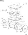
FIG. 3 is an exploded perspective view illustrating the configuration of the power supply device. -
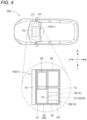
FIG. 4 is a diagram illustrating a mounting mode of a power supply module on a vehicle. -
FIG. 5 is a diagram illustrating a mounting mode of the power supply module on the vehicle. -
FIG. 6 is a diagram illustrating a mounting mode of the power supply module on the vehicle. -
FIG. 7 is a diagram illustrating a mounting mode of the power supply module on the vehicle. -
FIG. 8 is a diagram illustrating a mounting mode of the power supply module on the vehicle. -
FIG. 9 is a diagram illustrating a mounting mode of the power supply module on the vehicle. -
FIG. 10 is a diagram illustrating a mounting mode of the power supply module on the vehicle. -
FIG. 11 is a diagram illustrating a mounting mode of the power supply module on the vehicle. - A power supply device according to the present invention is mounted on a vehicle. Hereinafter, a
power supply device 1 of the present embodiment will be described. -
FIG. 1 is a block diagram schematically illustrating a configuration of thepower supply device 1. As illustrated inFIG. 1 , thepower supply device 1 includes apower supply module 100 including aninverter 10, adischarge unit 14, afirst capacitor 15, aconverter 20, asecond capacitor 25, areactor coil 30, acontrol unit 50, and acollision detection unit 70. Each functional unit is constructed by hardware, software, or both with a CPU as a core member in order to perform the processing related to the output of DC power described above. - The
inverter 10 converts AC power into DC power and outputs the DC power. The AC power refers to electric power composed of an AC voltage whose voltage value oscillates at a predetermined cycle. Specifically, the AC voltage corresponds to an AC voltage of, for example, 200 V (effective value) oscillating at a commercial frequency (for example, 50 Hz or 60 Hz) and extracted from a commercial power supply supplied in a single-phase three-wire system. The DC power refers to electric power composed of a DC voltage with a constant voltage value (excluding a ripple voltage) with respect to a reference voltage. In the present embodiment, AC power from the commercial power supply is supplied to theinverter 10. Theinverter 10 converts the AC power composed of such an AC voltage into DC power including a DC voltage. Theinverter 10 outputs the DC power generated by conversion from AC power to theconverter 20 to be described later. - The
first capacitor 15 is provided between the output terminals of theinverter 10. Between the output terminals of theinverter 10 is between a positive electrode terminal and a negative electrode terminal from which the DC power generated by theinverter 10 is output. Therefore, as illustrated inFIG. 1 , thefirst capacitor 15 is provided between the positive electrode terminal and the negative electrode terminal of theinverter 10. Thefirst capacitor 15 smooths the DC voltage converted by theinverter 10. - The
reactor coil 30 is provided between theinverter 10 and asupply unit 2 that supplies AC power to theinverter 10. - The
converter 20 includes aninput unit 21, afirst conversion unit 22, asecond conversion unit 23, and atransformer 24. In the present embodiment, thetransformer 24 is an isolation multi-port transformer including a primary winding 24A, asecondary winding 24B, and atertiary winding 24C. - The
input unit 21 causes DC power from theinverter 10 to oscillate at a predetermined cycle, and inputs the DC power to the primary winding 24A. The DC power from theinverter 10 is DC power output from theinverter 10. By theinput unit 21 causes the DC power from theinverter 10 to oscillate at a predetermined cycle, AC power oscillating at a predetermined cycle is input to the primary winding 24A. - A current (alternating current) corresponding to the turn ratio of the
primary winding 24A and thesecondary winding 24B flows through thesecondary winding 24B, and a voltage (alternating voltage) corresponding to the turn ratio of theprimary winding 24A and thesecondary winding 24B is generated. Thefirst conversion unit 22 converts AC power generated in the secondary winding 24B into DC power composed of a DC voltage having a first voltage value capable of charging a first battery 3. The first battery 3 is a battery mounted on a vehicle 200 (seeFIG. 4 ) charged by thepower supply device 1, and is charged on the basis of the DC power output from thefirst conversion unit 22. The first battery 3 is charged with a DC voltage having a predetermined voltage value, and the voltage value of the DC voltage constituting the DC power output from theinverter 10 is about the voltage value (200 V) of the AC voltage input to theinverter 10. Thefirst conversion unit 22 boosts the voltage value of the DC voltage output frominverter 10 to a DC voltage having a voltage value (corresponds to "first voltage value", for example, several hundred V) necessary for charging the first battery 3. - The
second capacitor 25 is provided between the output terminals of thefirst conversion unit 22. Between the output terminals of thefirst conversion unit 22 is between a positive electrode terminal and a negative electrode terminal from which the DC power generated by thefirst conversion unit 22 is output. Therefore, as illustrated inFIG. 1 , thesecond capacitor 25 is provided between the positive electrode terminal and the negative electrode terminal of thefirst conversion unit 22. Thesecond capacitor 25 smooths the DC voltage constituting the AC power converted by thefirst conversion unit 22. - A current (alternating current) corresponding to the turn ratio of the primary winding 24A and the tertiary winding 24C flows through the tertiary winding 24C, and a voltage (alternating voltage) corresponding to the turn ratio of the primary winding 24A and the tertiary winding 24C is generated. The
second conversion unit 23 converts AC power generated in the tertiary winding 24C into DC power composed of a DC voltage having a second voltage value (for example, 12 V) lower than the first voltage value capable of charging asecond battery 4 different from the first battery 3. Thesecond battery 4 is a battery mounted on thevehicle 200 charged by thepower supply device 1, and is charged on the basis of the DC power output from thesecond conversion unit 23. Thesecond battery 4 is charged with a DC voltage having a predetermined voltage value, and the voltage value of the DC voltage constituting the DC power output from theinverter 10 is about the voltage value (200 V) of the AC voltage input to theinverter 10. Thefirst conversion unit 22 steps down the voltage value of the DC voltage output frominverter 10 to a DC voltage having a voltage value (corresponds to "second voltage value", for example, 12 V) necessary for charging thesecond battery 4. - A
third capacitor 27 is provided between the output terminals of thesecond conversion unit 23. For example, thesecond conversion unit 23 can be configured to convert AC power generated in the tertiary winding 24C into DC power composed of the DC voltage having the second voltage value by synchronous rectification. - The
control unit 50 drives each of a plurality of switching elements (not illustrated) provided in theinverter 10. As a result, as described above, theinverter 10 can convert AC power supplied from thesupply unit 2 into DC power on the basis of the driving of the switching elements. - Furthermore, the
control unit 50 drives each of a plurality of switching elements (not illustrated) provided in theconverter 20. As a result, the DC power from theinverter 10 oscillates to be input to the primary winding 24A, and the AC power corresponding to the turn ratio of the primary winding 24A and the secondary winding 24B can be generated in the secondary winding 24B. - Moreover, the
control unit 50 drives each of a plurality of switching elements (not illustrated) provided in thefirst conversion unit 22. As a result, the AC voltage generated in the secondary winding 24B is converted into a DC voltage. The first battery 3 is charged with the DC voltage. - Furthermore, the
control unit 50 drives each of a plurality of switching elements (not illustrated) provided in thesecond conversion unit 23. As a result, the AC voltage generated in the tertiary winding 24C is converted into a DC voltage. Thesecond battery 4 is charged with the DC voltage. - Here, when the
power supply device 1 is driven, thefirst capacitor 15 and thesecond capacitor 25 are charged as described above. Thepower supply module 100 includes thedischarge unit 14 that discharges thefirst capacitor 15 and thesecond capacitor 25. In the present embodiment, thedischarge unit 14 includes a resistor (so-called "discharge resistor"). Aresistor 16 is provided in parallel with thefirst capacitor 15 as a discharge resistor that discharges thefirst capacitor 15, and aresistor 26 is provided in parallel with thesecond capacitor 25 as a discharge resistor that discharges thesecond capacitor 25. In the present embodiment, theresistor 16 and thefirst capacitor 15 are provided in parallel to each other, and theresistor 26 and thesecond capacitor 25 are provided in parallel to each other. Therefore, when the power supply to thefirst capacitor 15 is stopped, the first capacitor 15 (the charges of the first capacitor 15) is automatically discharged by theresistor 16, and when the power supply to thesecond capacitor 25 is stopped, the second capacitor 25 (the charges of the second capacitor 25) is automatically discharged by theresistor 26. - The
collision detection unit 70 detects a collision of thevehicle 200.FIG. 2 illustrates a detection circuit constituting thecollision detection unit 70 of the present embodiment. Thecollision detection unit 70 includes a plurality of resistors R1 and R2 connected in series between a first potential to which the output voltage of thesecond battery 4 is applied and a second potential lower than the first potential, and detects a collision on the basis of voltage values divided by the plurality of resistors R1 and R2. The first potential to which the output voltage of thesecond battery 4 is applied means the same potential as the output voltage of thesecond battery 4. In the present embodiment, the output terminal of thesecond battery 4 corresponds to such a portion of the first potential. The second potential lower than the first potential refers to a voltage value lower than the voltage value of the output voltage of thesecond battery 4, and corresponds to, for example, the ground potential. Therefore, in the present embodiment, the resistor R1 and the resistor R2 connected in series are provided between the output terminal of thesecond battery 4 and the ground potential. - In the present embodiment, the
collision detection unit 70 includes the resistor R1, the resistor R2, and a capacitor C1. In the resistor R1, one terminal is connected to the output terminal of thesecond battery 4, and the other terminal is connected to thecontrol unit 50. In the resistor R2, one terminal is connected to the other terminal of the resistor R1, and the other terminal is grounded. As a result, the output voltage of thesecond battery 4 is divided by the resistor R1 and the resistor R2 between the output voltage and the ground potential. - In addition, a node at which the resistor R1 and the resistor R2 are connected to each other is connected to the
control unit 50. The voltage value divided by the resistor R1 and the resistor R2 is thus input to thecontrol unit 50. Furthermore, the capacitor C1 is provided in parallel with the resistor R2 as a filter that smoothes a divided voltage. - For example, in a case where disconnection of a connection line connecting the
second battery 4 and thecontrol unit 50, missing or short-circuit of the resistor R1, missing or short-circuit of the resistor R2, or the like occurs due to the collision of thevehicle 200, the voltage value input to thecontrol unit 50 is different from an expected value (a value obtained by dividing the potential difference between the output voltage of thesecond battery 4 and the ground potential by the resistor R1 and the resistor R2), so that thecontrol unit 50 can detect the collision of thevehicle 200. -
FIG. 3 illustrates a developed perspective view of thepower supply module 100. In the present embodiment, as illustrated inFIG. 3 , thepower supply module 100 is configured in a manner that an on board charger (OBC)board 120, amotor drive board 130, and acontrol board 140 that controls theOBC board 120 and themotor drive board 130 are housed in ahousing 110. Thepower supply module 100 has afirst space 111. TheOBC board 120, themotor drive board 130, and thecontrol board 140 are different boards, and are housed in thefirst space 111 in mutually parallel postures. Hereinafter, the direction perpendicular to the plate surface of theOBC board 120 is referred to as "vertical direction", the direction along the vertical direction in which thecontrol board 140 is viewed from theOBC board 120 and themotor drive board 130 is referred to as "upper direction", "upper side", or the like, and the direction in which theOBC board 120 and themotor drive board 130 are viewed from thecontrol board 140 is referred to as "lower direction", "lower side", or the like. - The
housing 110 has asecond space 112 and athird space 113 partitioned from thefirst space 111. Thesecond space 112 and thethird space 113 are located on the lower side of thefirst space 111. Amotor 106 driven by themotor drive board 130 is housed in thesecond space 112, and agear mechanism 107 that decelerates and outputs the rotation of themotor 106 is housed in thethird space 113. Thehousing 110 has anopening 110a on the upper side of thefirst space 111, and theOBC board 120, themotor drive board 130, and thecontrol board 140 are housed in thefirst space 111 from theopening 110a. Theopening 110a is closed by alid 114, and thus thefirst space 111 becomes a closed space. Thesecond space 112 houses themotor 106 from the side, and is closed by amotor cover 115 fastened with a bolt (not illustrated) to become a closed space. Amotor shaft 106a extends from themotor 106 to both sides along the rotation axis, and onemotor shaft 106a penetrates themotor cover 115 and is exposed to the outside of thehousing 110. Theother motor shaft 106a penetrates to thethird space 113. Thethird space 113 houses thegear mechanism 107 from the side, and is closed by agear cover 116 fastened with a bolt (not shown) to become a closed space. Theother motor shaft 106a extending from thesecond space 112 is coupled to thegear mechanism 107, and the rotation of themotor 106 is input via themotor shaft 106a. Thegear mechanism 107 decelerates the rotation of themotor 106 and outputs the decelerated rotation from agear shaft 107a. Thegear shaft 107a penetrates thegear cover 116 and is exposed to the outside of thehousing 110. - At least the
inverter 10 and theconverter 20 are mounted on theOBC board 120. At least a drive inverter MI (seeFIG. 4 ) that controls a drive current for driving themotor 106 is mounted on themotor drive board 130. At least thecontrol unit 50 is mounted on thecontrol board 140. - In the present embodiment, the
OBC board 120 and themotor drive board 130 are arranged side by side in the horizontal direction. Thecontrol board 140 is disposed so as to overlap theOBC board 120 and themotor drive board 130 when viewed along the vertical direction (in vertical view). The connection between theOBC board 120 and thecontrol board 140 and the connection between themotor drive board 130 and thecontrol board 140 are performed via board-to-board connectors (not illustrated). -
FIG. 4 illustrates a mounting position of thepower supply module 100 in thevehicle 200. In the present embodiment, thepower supply module 100 is provided on the front side of the central portion in the front-rear direction of thevehicle 200 and at the position of the central portion in the vehicle width direction of thevehicle 200. Here, thepower supply module 100 includes a high-voltage system component HP and a low-voltage system component LP classified based on the voltage value of an applied voltage. For example, the functional unit having an applied voltage of 100 V or more is classified as the high-voltage system component HP, and the functional unit having an applied voltage of less than 100 V is classified as the low-voltage system component LP. In this case, the high-voltage system component HP includes at least theinverter 10, thefirst capacitor 15, theinput unit 21, thefirst conversion unit 22, thesecond capacitor 25, and the drive inverter MI, and the low-voltage system component LP includes at least thesecond conversion unit 23 and thecontrol unit 50. - In the
power supply device 1, the low-voltage system component LP is provided on the outer edge portion side of thevehicle 200 in plan view with respect to the high-voltage system component HP. In the present embodiment, the outer edge portion side of thevehicle 200 in plan view of thevehicle 200 means, in the front-rear direction of thevehicle 200, a side away from the central portion in the front-rear direction in the front direction and in the rear direction. In addition, in the width direction of thevehicle 200, it means a side away from the central portion in the width direction in the left direction and in the right direction. In the present embodiment, for easy understanding, it is assumed that the center side and the outer edge portion side are defined only in the front-rear direction of thevehicle 200. - In this case, as illustrated in
FIG. 4 , in plan view of thevehicle 200, thesecond conversion unit 23 included in the low-voltage system component LP is provided on the outer edge portion side in the front-rear direction of thevehicle 200 with respect to theinverter 10, theinput unit 21, and thefirst conversion unit 22 included in the high-voltage system component HP. Here, as illustrated inFIG. 4 , in the present embodiment, thepower supply module 100 is provided on the front side of the central portion in the front-rear direction of thevehicle 200 in plan view. In view of thepower supply module 100, the outer edge portion of thevehicle 200 corresponds to the front side in the traveling direction, which is one of the front side in the traveling direction and the rear side in the traveling direction of thevehicle 200. Therefore, thesecond conversion unit 23 included in the low-voltage system component LP is provided on the front side in the traveling direction of thevehicle 200 with respect to theinverter 10, theinput unit 21, and thefirst conversion unit 22 included in the high-voltage system component HP. As a result, even if thevehicle 200 collides, the high-voltage system component HP (for example, theinverter 10, theinput unit 21, and the first conversion unit 22) is not exposed to the outside of the vehicle and can be hardly damaged. - As described above, the
first capacitor 15 and thesecond capacitor 25 are included in the high-voltage system component HP. As a result, even if thevehicle 200 collides, the high-voltage system component HP can be hardly damaged. However, the discharge unit 14 (theresistor 16 and the resistor 26) is provided on the center side opposite to the outer edge portion side of thevehicle 200 in thepower supply module 100 so that thefirst capacitor 15 and thesecond capacitor 25 can be reliably discharged even in such a case. That is, in order to reliably discharge the charges stored in thefirst capacitor 15 and thesecond capacitor 25 without damaging theresistor 16 and theresistor 26 even when thevehicle 200 collides, the first capacitor and the second capacitor are provided on the center side in the front-rear direction of thevehicle 200 in the present embodiment. As described above, thefirst capacitor 15 and thesecond capacitor 25 are provided on the center side in the traveling direction of thevehicle 200, and theresistor 16 and theresistor 26 may be provided near thefirst capacitor 15 and thesecond capacitor 25. More preferably, theresistor 16 and theresistor 26 are provided further behind thefirst capacitor 15 and the second capacitor 25 (on the center side in the traveling direction of the vehicle 200). Note that the positions of theresistor 16 and theresistor 26 along the vehicle width direction of thevehicle 200 are not particularly limited in the present embodiment. - In the present embodiment, the
collision detection unit 70 is provided on the outer edge portion side of thevehicle 200 in thepower supply module 100. As described above, thecollision detection unit 70 detects whether or not thevehicle 200 has collided based on the voltage value of the voltage input to thecontrol unit 50. In order to detect whether or not there has been a collision of thevehicle 200, thecollision detection unit 70 is preferably provided in a part of thevehicle 200 that is most affected by the collision (a part that is highly likely to be damaged). Therefore, the resistor R1 and the resistor R2 constituting thecollision detection unit 70 are provided on the outer edge side of the vehicle 200 (in the present embodiment, the front side along the traveling direction of the vehicle 200) in thepower supply module 100. Note that thecollision detection unit 70 may be provided at a further outer edge portion of the vehicle 200 (for example, the front end portion of the vehicle 200) with respect to thepower supply module 100. The closer to the outer edge portion of thevehicle 200, the larger the influence of the collision, so that the collision of thevehicle 200 can be detected more reliably. - With the above configuration, the high-voltage system component HP can be hardly broken even when the
vehicle 200 collides, and even if thepower supply module 100 is damaged, thefirst capacitor 15 andsecond capacitor 25 with a large capacity can be discharged. Therefore, it is possible to rescue a person after discharging thefirst capacitor 15 and thesecond capacitor 25. In addition, for example, as compared with a sensor separately provided for detecting the collision of thevehicle 200, thecollision detection unit 70 of the present embodiment can be configured with a simple circuit. As a result, it is possible to detect the collision of thevehicle 200 at a lower cost than a case where a separate sensor is provided. - In the above embodiment, it has been described that the
power supply module 100 includes thedischarge unit 14. However, thepower supply module 100 does not need to include thedischarge unit 14. - Furthermore, in the above embodiment, it has been described that the
discharge unit 14 includes theresistor 16 and theresistor 26, but this configuration is merely an example, and thedischarge unit 14 may be configured using, for example, a switching element instead of theresistor 16 and theresistor 26. - Moreover, in the above embodiment, it has been described that the
discharge unit 14 is provided on the center side opposite to the outer edge portion side of thevehicle 200 in thepower supply module 100. However, thedischarge unit 14 may be provided on the outer edge portion side of thevehicle 200. - In the above embodiment, it has been described that the
power supply module 100 includes thecollision detection unit 70. However, thepower supply module 100 does not need to include thecollision detection unit 70. - In the present embodiment, it has been described that the
collision detection unit 70 is provided on the outer edge portion side of thevehicle 200 in thepower supply module 100. However, thecollision detection unit 70 is provided on the center side of thevehicle 200 in thepower supply module 100. - In the above embodiment, it has been described that the
collision detection unit 70 includes the plurality of resistors R1 and R2 connected in series between the first potential to which the output voltage of thesecond battery 4 is applied and the second potential lower than the first potential, and detects a collision on the basis of voltage values divided by the plurality of resistors R1 and R2. However, in thecollision detection unit 70, the plurality of resistors R1 and R2 may be connected in series between the potential to which the output voltage of the first battery 3 is applied and the second potential lower than the potential, or the plurality of resistors R1 and R2 may be connected in series between the potential to which the output voltage of the first battery 3 is applied and the first potential to which the output voltage of thesecond battery 4 is applied. Even in this case, it is possible to detect the collision of thevehicle 200. - In the above embodiment, it has been described that the outer edge portion is the front side in the traveling direction of the
vehicle 200. For example, as illustrated inFIG. 5 , thepower supply module 100 may be provided on the rear side with respect to the central portion in the front-rear direction of thevehicle 200. In this case, the outer edge portion is the rear side in the traveling direction of thevehicle 200. Therefore, the low-voltage system component LP is preferably provided on the rear side of thevehicle 200 with respect to the high-voltage system component HP. - Furthermore, for example, the outer edge portion may be one of the left side and the right side in the width direction of the
vehicle 200. For example, as illustrated inFIG. 6 , in a case where thepower supply module 100 is provided on the left side with respect to the central portion along the vehicle width direction of thevehicle 200, the low-voltage system component LP may be provided on the left side of thevehicle 200 with respect to the high-voltage system component HP. In addition, as illustrated inFIG. 7 , in a case where thepower supply module 100 is provided on the right side with respect to the central portion along the vehicle width direction of thevehicle 200, the low-voltage system component LP may be provided on the right side of thevehicle 200 with respect to the high-voltage system component HP. - Furthermore, the outer edge portion of the
vehicle 200 can be set on the basis of both the front-rear direction and the width direction of thevehicle 200. For example, as illustrated inFIG. 8 , in a case where thepower supply module 100 is provided in the left front portion of thevehicle 200, the low-voltage system component LP may be provided front and on the left side along the outer edge portion of thevehicle 200, and the high-voltage system component HP may be provided on the center side (central side) of thevehicle 200 with respect to the low-voltage system component LP. For example, as illustrated inFIG. 9 , in a case where thepower supply module 100 is provided in the right front portion of thevehicle 200, the low-voltage system component LP may be provided front and on the right side along the outer edge portion of thevehicle 200, and the high-voltage system component HP may be provided on the center side (central side) of thevehicle 200 with respect to the low-voltage system component LP. - Furthermore, as illustrated in
FIG. 10 , in a case where thepower supply module 100 is provided in the left rear portion of thevehicle 200, the low-voltage system component LP may be provided rear and on the left side along the outer edge portion of thevehicle 200, and the high-voltage system component HP may be provided on the center side (central side) of thevehicle 200 with respect to the low-voltage system component LP. Moreover, as illustrated inFIG. 11 , in a case where thepower supply module 100 is provided in the right rear portion of thevehicle 200, the low-voltage system component LP may be provided rear and on the right side along the outer edge portion of thevehicle 200, and the high-voltage system component HP may be provided on the center side (central side) of thevehicle 200 with respect to the low-voltage system component LP. - Hereinafter, the outline of the
power supply device 1 described above will be described. -
- (1) A characteristic configuration of the
power supply device 1 according to the present invention is thepower supply device 1 mounted on thevehicle 200, the power supply device includes thepower supply module 100, the power supply module includes theinverter 10 that converts AC power into DC power and outputs the DC power, theconverter 20 including thefirst conversion unit 22 that converts the DC power from theinverter 10 into DC power composed of a DC voltage having a first voltage value chargeable the first battery 3, and thesecond conversion unit 23 that converts the DC power into DC power composed of a DC voltage having a second voltage value lower than the first voltage value chargeable thesecond battery 4 different from the first battery 3, and thecontrol unit 50 that drives theinverter 10 and drives theconverter 20, thepower supply module 100 includes the high-voltage system component HP including theinverter 10 and thefirst conversion unit 22 and the low-voltage system component LP including thesecond conversion unit 23 based on a voltage value of a voltage to be applied, and the low-voltage system component LP is provided on an outer edge portion side of thevehicle 200 in plan view with respect to the high-voltage system component HP.
For example, in a case where thevehicle 200 collides, the outer edge portion side of thevehicle 200 is often more damaged than the central portion side of the vehicle. In addition, when the functional units of thepower supply module 100 are classified into the high-voltage system component HP and the low-voltage system component LP, the high-voltage system component HP has a higher voltage value of the applied voltage than the low-voltage system component LP. Therefore, according to the above characteristic configuration, the low-voltage system component LP can be disposed on the outer edge portion side of thevehicle 200 and the high-voltage system component HP can be disposed on the central portion side of thevehicle 200, and thus even if thevehicle 200 collides, the high-voltage system component HP having a high voltage value of the applied voltage can be prevented from being exposed to the outside of the vehicle. Furthermore, since the low-voltage system component LP and the high-voltage system component HP are arranged separately from each other, the influence of noise from one of the high-voltage system component HP and the low-voltage system component LP to the other can be reduced. - (2) In the
power supply device 1 according to (1), preferably, thepower supply module 100 further includes thefirst capacitor 15 provided between output terminals of theinverter 10, thesecond capacitor 25 provided between output terminals of thefirst conversion unit 22, and thedischarge unit 14 that discharges thefirst capacitor 15 and thesecond capacitor 25, and thedischarge unit 14 is provided on a center side opposite to the outer edge portion side of thevehicle 200 in thepower supply module 100.
According to this configuration, since thedischarge unit 14 can be disposed at a part hardly damaged when thevehicle 200 collides, thefirst capacitor 15 and thesecond capacitor 25 can be discharged even when thevehicle 200 collides. Therefore, it is possible to rescue a person or collect the vehicle in a state where thefirst capacitor 15 and thesecond capacitor 25 are discharged. - (3) In the
power supply device 1 according to (1), preferably, thepower supply module 100 further includes thecollision detection unit 70 that detects a collision of thevehicle 200, and thecollision detection unit 70 is provided on the outer edge portion side of thevehicle 200 in thepower supply module 100.
According to this configuration, thecollision detection unit 70 can be disposed at a part easily damaged when thevehicle 200 collides. Therefore, the collision of thevehicle 200 can be detected based on the damage of thecollision detection unit 70. - (4) In the
power supply device 1 according to (3), preferably, thecollision detection unit 70 includes a plurality of resistors R1, R2 connected in series between a first potential to which an output voltage of thesecond battery 4 is applied and a second potential lower than the first potential, and detects the collision based on a voltage value divided by the plurality of resistors R1, R2.
According to this configuration, for example, the voltage value divided due to the disconnection or short-circuit in thecollision detection unit 70 caused by a collision can be made different from a voltage value before collision. Therefore, it is possible to easily detect the collision of thevehicle 200. - (5) In the
power supply device 1 according to (1) to (4), the outer edge portion is preferably one of a front side in a traveling direction and a rear side in the traveling direction of thevehicle 200. - According to this configuration, the arrangement of the high-voltage system component HP and the low-voltage system component LP can be easily set based on the installation place of the
power supply module 100 in thevehicle 200. - The present invention can be used for a power supply device mounted on a vehicle.
- 1: Power supply device, 3: First battery, 4: Second battery, 10: Inverter, 14: Discharge unit, 15: First capacitor, 20: Converter, 22: First conversion unit, 23: Second conversion unit, 25: Second capacitor, 50: Control unit, 70: Collision detection unit, 100: Power supply module, 200: Vehicle, HP: High-voltage system component, LP: Low-voltage system component, R1: Resistor, and R2: Resistor
Claims (5)
- A power supply device mounted on a vehicle, the power supply device comprising a power supply module,the power supply module includesan inverter that converts AC power into DC power and outputs the DC power,a converter including a first conversion unit that converts the DC power from the inverter into DC power composed of a DC voltage having a first voltage value chargeable a first battery, and a second conversion unit that converts the DC power into DC power composed of a DC voltage having a second voltage value lower than the first voltage value chargeable a second battery different from the first battery, anda control unit that drives the inverter and drives the converter,wherein the power supply module includes a high-voltage system component including the inverter and the first conversion unit and a low-voltage system component including the second conversion unit based on a voltage value of a voltage to be applied, and the low-voltage system component is provided on an outer edge portion side of the vehicle in plan view with respect to the high-voltage system component.
- The power supply device according to claim 1, wherein the power supply module further includes a first capacitor provided between output terminals of the inverter, a second capacitor provided between output terminals of the first conversion unit, and a discharge unit that discharges the first capacitor and the second capacitor, and
the discharge unit is provided on a center side opposite to the outer edge portion side of the vehicle in the power supply module. - The power supply device according to claim 1, wherein the power supply module further includes a collision detection unit that detects a collision of the vehicle, and
the collision detection unit is provided on the outer edge portion side of the vehicle in the power supply module. - The power supply device according to claim 3, wherein the collision detection unit includes a plurality of resistors connected in series between a first potential to which an output voltage of the second battery is applied and a second potential lower than the first potential, and detects the collision based on a voltage value divided by the plurality of resistors.
- The power supply device according to any one of claims 1 to 4, wherein the outer edge portion is one of a front side in a traveling direction and a rear side in the traveling direction of the vehicle.
Applications Claiming Priority (2)
| Application Number | Priority Date | Filing Date | Title |
|---|---|---|---|
| JP2022191720 | 2022-11-30 | ||
| PCT/JP2023/040376 WO2024116771A1 (en) | 2022-11-30 | 2023-11-09 | Power supply device |
Publications (2)
| Publication Number | Publication Date |
|---|---|
| EP4579988A1 true EP4579988A1 (en) | 2025-07-02 |
| EP4579988A4 EP4579988A4 (en) | 2025-12-17 |
Family
ID=91323530
Family Applications (1)
| Application Number | Title | Priority Date | Filing Date |
|---|---|---|---|
| EP23897424.0A Pending EP4579988A4 (en) | 2022-11-30 | 2023-11-09 | POWER SUPPLY DEVICE |
Country Status (5)
| Country | Link |
|---|---|
| US (1) | US20260131660A1 (en) |
| EP (1) | EP4579988A4 (en) |
| JP (1) | JPWO2024116771A1 (en) |
| CN (1) | CN120153547A (en) |
| WO (1) | WO2024116771A1 (en) |
Family Cites Families (9)
| Publication number | Priority date | Publication date | Assignee | Title |
|---|---|---|---|---|
| JP4253684B1 (en) * | 2007-12-05 | 2009-04-15 | トヨタ自動車株式会社 | Vehicle drive device |
| JP2009148051A (en) * | 2007-12-13 | 2009-07-02 | Toyota Motor Corp | Cell monitoring device for fuel cell and fuel cell system provided with the same |
| US8773150B2 (en) * | 2011-04-18 | 2014-07-08 | Toyota Jidosha Kabushiki Kaisha | Vehicle crash detection device |
| US9145058B2 (en) * | 2011-11-30 | 2015-09-29 | Honda Motor Co., Ltd. | Electric vehicle |
| JP2013187995A (en) * | 2012-03-07 | 2013-09-19 | Toyota Industries Corp | Switching power supply device |
| JP5911622B1 (en) * | 2015-03-25 | 2016-04-27 | 三菱電機株式会社 | In-vehicle battery power supply |
| JP6731902B2 (en) * | 2017-11-27 | 2020-07-29 | 矢崎総業株式会社 | Power supply system |
| JP2020061892A (en) | 2018-10-12 | 2020-04-16 | パナソニックIpマネジメント株式会社 | Voltage conversion device |
| JP6973669B2 (en) * | 2019-02-01 | 2021-12-01 | 住友電気工業株式会社 | Power supply system and vehicles equipped with it |
-
2023
- 2023-11-09 WO PCT/JP2023/040376 patent/WO2024116771A1/en not_active Ceased
- 2023-11-09 EP EP23897424.0A patent/EP4579988A4/en active Pending
- 2023-11-09 CN CN202380076188.5A patent/CN120153547A/en active Pending
- 2023-11-09 US US19/119,497 patent/US20260131660A1/en active Pending
- 2023-11-09 JP JP2024561300A patent/JPWO2024116771A1/ja active Pending
Also Published As
| Publication number | Publication date |
|---|---|
| CN120153547A (en) | 2025-06-13 |
| EP4579988A4 (en) | 2025-12-17 |
| WO2024116771A1 (en) | 2024-06-06 |
| US20260131660A1 (en) | 2026-05-14 |
| JPWO2024116771A1 (en) | 2024-06-06 |
Similar Documents
| Publication | Publication Date | Title |
|---|---|---|
| US9886802B2 (en) | Vehicle power supply device and malfunction diagnosis method thereof | |
| EP3875304B1 (en) | Electrically powered vehicle and method for controlling electrically powered vehicle | |
| US10843569B2 (en) | Vehicle having power control unit | |
| CN101734168B (en) | High-voltage electrical component unit for vehicles | |
| US8878483B2 (en) | Electronics unit with current sensing | |
| EP2218607A1 (en) | Electric charging system and its operation method | |
| US20100200377A1 (en) | Discharge mechanism and vehicle | |
| EP2596982A2 (en) | Power supply system for electric vehicle and control method thereof | |
| WO2010026715A1 (en) | Power supply device for vehicle | |
| JP2003180002A (en) | Power supply for vehicles | |
| US9075096B2 (en) | Collision detection device for vehicle | |
| CN110024212B (en) | Composite battery, motor vehicle provided with same, and railroad regenerative power storage device | |
| US20260131660A1 (en) | Power supply device | |
| KR100256732B1 (en) | Battery diagnose method of electric vehicle | |
| JP6595934B2 (en) | Vehicle power supply | |
| US8720621B2 (en) | Electrically driven vehicle | |
| JP3379467B2 (en) | AC power supply for vehicles | |
| JP2015035865A (en) | Power converter | |
| JP6790871B2 (en) | Electric vehicle power supply | |
| CN114929502A (en) | Power distribution device | |
| WO2022091309A1 (en) | Electricity storage machine | |
| KR20210116176A (en) | Emergency power supply device for eco-friendly vehicle | |
| US20250303925A1 (en) | Control apparatus for secondary battery | |
| JP7726116B2 (en) | Control device, vehicle, and control program | |
| CN222601429U (en) | Spacer, conductive bar assembly and vehicle |
Legal Events
| Date | Code | Title | Description |
|---|---|---|---|
| STAA | Information on the status of an ep patent application or granted ep patent |
Free format text: STATUS: THE INTERNATIONAL PUBLICATION HAS BEEN MADE |
|
| PUAI | Public reference made under article 153(3) epc to a published international application that has entered the european phase |
Free format text: ORIGINAL CODE: 0009012 |
|
| STAA | Information on the status of an ep patent application or granted ep patent |
Free format text: STATUS: REQUEST FOR EXAMINATION WAS MADE |
|
| 17P | Request for examination filed |
Effective date: 20250327 |
|
| AK | Designated contracting states |
Kind code of ref document: A1 Designated state(s): AL AT BE BG CH CY CZ DE DK EE ES FI FR GB GR HR HU IE IS IT LI LT LU LV MC ME MK MT NL NO PL PT RO RS SE SI SK SM TR |
|
| A4 | Supplementary search report drawn up and despatched |
Effective date: 20251117 |
|
| RIC1 | Information provided on ipc code assigned before grant |
Ipc: H02J 7/00 20060101AFI20251111BHEP Ipc: B60L 3/00 20190101ALI20251111BHEP Ipc: B60L 53/22 20190101ALI20251111BHEP Ipc: B60L 58/20 20190101ALI20251111BHEP |
|
| DAV | Request for validation of the european patent (deleted) | ||
| DAX | Request for extension of the european patent (deleted) |