EP4579938A1 - Non-aqueous electrolyte secondary battery - Google Patents
Non-aqueous electrolyte secondary battery Download PDFInfo
- Publication number
- EP4579938A1 EP4579938A1 EP23857034.5A EP23857034A EP4579938A1 EP 4579938 A1 EP4579938 A1 EP 4579938A1 EP 23857034 A EP23857034 A EP 23857034A EP 4579938 A1 EP4579938 A1 EP 4579938A1
- Authority
- EP
- European Patent Office
- Prior art keywords
- nonaqueous electrolyte
- insulating plate
- secondary battery
- electrolyte secondary
- aperture
- Prior art date
- Legal status (The legal status is an assumption and is not a legal conclusion. Google has not performed a legal analysis and makes no representation as to the accuracy of the status listed.)
- Pending
Links
Images


Classifications
-
- H—ELECTRICITY
- H01—ELECTRIC ELEMENTS
- H01M—PROCESSES OR MEANS, e.g. BATTERIES, FOR THE DIRECT CONVERSION OF CHEMICAL ENERGY INTO ELECTRICAL ENERGY
- H01M50/00—Constructional details or processes of manufacture of the non-active parts of electrochemical cells other than fuel cells, e.g. hybrid cells
- H01M50/10—Primary casings; Jackets or wrappings
- H01M50/102—Primary casings; Jackets or wrappings characterised by their shape or physical structure
- H01M50/107—Primary casings; Jackets or wrappings characterised by their shape or physical structure having curved cross-section, e.g. round or elliptic
-
- H—ELECTRICITY
- H01—ELECTRIC ELEMENTS
- H01M—PROCESSES OR MEANS, e.g. BATTERIES, FOR THE DIRECT CONVERSION OF CHEMICAL ENERGY INTO ELECTRICAL ENERGY
- H01M10/00—Secondary cells; Manufacture thereof
- H01M10/05—Accumulators with non-aqueous electrolyte
- H01M10/056—Accumulators with non-aqueous electrolyte characterised by the materials used as electrolytes, e.g. mixed inorganic/organic electrolytes
- H01M10/0564—Accumulators with non-aqueous electrolyte characterised by the materials used as electrolytes, e.g. mixed inorganic/organic electrolytes the electrolyte being constituted of organic materials only
- H01M10/0566—Liquid materials
- H01M10/0567—Liquid materials characterised by the additives
-
- H—ELECTRICITY
- H01—ELECTRIC ELEMENTS
- H01M—PROCESSES OR MEANS, e.g. BATTERIES, FOR THE DIRECT CONVERSION OF CHEMICAL ENERGY INTO ELECTRICAL ENERGY
- H01M10/00—Secondary cells; Manufacture thereof
- H01M10/05—Accumulators with non-aqueous electrolyte
- H01M10/058—Construction or manufacture
- H01M10/0587—Construction or manufacture of accumulators having only wound construction elements, i.e. wound positive electrodes, wound negative electrodes and wound separators
-
- H—ELECTRICITY
- H01—ELECTRIC ELEMENTS
- H01M—PROCESSES OR MEANS, e.g. BATTERIES, FOR THE DIRECT CONVERSION OF CHEMICAL ENERGY INTO ELECTRICAL ENERGY
- H01M50/00—Constructional details or processes of manufacture of the non-active parts of electrochemical cells other than fuel cells, e.g. hybrid cells
- H01M50/40—Separators; Membranes; Diaphragms; Spacing elements inside cells
- H01M50/471—Spacing elements inside cells other than separators, membranes or diaphragms; Manufacturing processes thereof
- H01M50/474—Spacing elements inside cells other than separators, membranes or diaphragms; Manufacturing processes thereof characterised by their position inside the cells
-
- H—ELECTRICITY
- H01—ELECTRIC ELEMENTS
- H01M—PROCESSES OR MEANS, e.g. BATTERIES, FOR THE DIRECT CONVERSION OF CHEMICAL ENERGY INTO ELECTRICAL ENERGY
- H01M50/00—Constructional details or processes of manufacture of the non-active parts of electrochemical cells other than fuel cells, e.g. hybrid cells
- H01M50/40—Separators; Membranes; Diaphragms; Spacing elements inside cells
- H01M50/471—Spacing elements inside cells other than separators, membranes or diaphragms; Manufacturing processes thereof
- H01M50/477—Spacing elements inside cells other than separators, membranes or diaphragms; Manufacturing processes thereof characterised by their shape
-
- H—ELECTRICITY
- H01—ELECTRIC ELEMENTS
- H01M—PROCESSES OR MEANS, e.g. BATTERIES, FOR THE DIRECT CONVERSION OF CHEMICAL ENERGY INTO ELECTRICAL ENERGY
- H01M50/00—Constructional details or processes of manufacture of the non-active parts of electrochemical cells other than fuel cells, e.g. hybrid cells
- H01M50/50—Current conducting connections for cells or batteries
- H01M50/572—Means for preventing undesired use or discharge
- H01M50/584—Means for preventing undesired use or discharge for preventing incorrect connections inside or outside the batteries
- H01M50/586—Means for preventing undesired use or discharge for preventing incorrect connections inside or outside the batteries inside the batteries, e.g. incorrect connections of electrodes
-
- H—ELECTRICITY
- H01—ELECTRIC ELEMENTS
- H01M—PROCESSES OR MEANS, e.g. BATTERIES, FOR THE DIRECT CONVERSION OF CHEMICAL ENERGY INTO ELECTRICAL ENERGY
- H01M50/00—Constructional details or processes of manufacture of the non-active parts of electrochemical cells other than fuel cells, e.g. hybrid cells
- H01M50/50—Current conducting connections for cells or batteries
- H01M50/572—Means for preventing undesired use or discharge
- H01M50/584—Means for preventing undesired use or discharge for preventing incorrect connections inside or outside the batteries
- H01M50/59—Means for preventing undesired use or discharge for preventing incorrect connections inside or outside the batteries characterised by the protection means
- H01M50/593—Spacers; Insulating plates
-
- H—ELECTRICITY
- H01—ELECTRIC ELEMENTS
- H01M—PROCESSES OR MEANS, e.g. BATTERIES, FOR THE DIRECT CONVERSION OF CHEMICAL ENERGY INTO ELECTRICAL ENERGY
- H01M10/00—Secondary cells; Manufacture thereof
- H01M10/05—Accumulators with non-aqueous electrolyte
- H01M10/052—Li-accumulators
- H01M10/0525—Rocking-chair batteries, i.e. batteries with lithium insertion or intercalation in both electrodes; Lithium-ion batteries
-
- H—ELECTRICITY
- H01—ELECTRIC ELEMENTS
- H01M—PROCESSES OR MEANS, e.g. BATTERIES, FOR THE DIRECT CONVERSION OF CHEMICAL ENERGY INTO ELECTRICAL ENERGY
- H01M2300/00—Electrolytes
- H01M2300/0017—Non-aqueous electrolytes
- H01M2300/0025—Organic electrolyte
- H01M2300/0028—Organic electrolyte characterised by the solvent
- H01M2300/0037—Mixture of solvents
- H01M2300/004—Three solvents
-
- Y—GENERAL TAGGING OF NEW TECHNOLOGICAL DEVELOPMENTS; GENERAL TAGGING OF CROSS-SECTIONAL TECHNOLOGIES SPANNING OVER SEVERAL SECTIONS OF THE IPC; TECHNICAL SUBJECTS COVERED BY FORMER USPC CROSS-REFERENCE ART COLLECTIONS [XRACs] AND DIGESTS
- Y02—TECHNOLOGIES OR APPLICATIONS FOR MITIGATION OR ADAPTATION AGAINST CLIMATE CHANGE
- Y02E—REDUCTION OF GREENHOUSE GAS [GHG] EMISSIONS, RELATED TO ENERGY GENERATION, TRANSMISSION OR DISTRIBUTION
- Y02E60/00—Enabling technologies; Technologies with a potential or indirect contribution to GHG emissions mitigation
- Y02E60/10—Energy storage using batteries
-
- Y—GENERAL TAGGING OF NEW TECHNOLOGICAL DEVELOPMENTS; GENERAL TAGGING OF CROSS-SECTIONAL TECHNOLOGIES SPANNING OVER SEVERAL SECTIONS OF THE IPC; TECHNICAL SUBJECTS COVERED BY FORMER USPC CROSS-REFERENCE ART COLLECTIONS [XRACs] AND DIGESTS
- Y02—TECHNOLOGIES OR APPLICATIONS FOR MITIGATION OR ADAPTATION AGAINST CLIMATE CHANGE
- Y02P—CLIMATE CHANGE MITIGATION TECHNOLOGIES IN THE PRODUCTION OR PROCESSING OF GOODS
- Y02P70/00—Climate change mitigation technologies in the production process for final industrial or consumer products
- Y02P70/50—Manufacturing or production processes characterised by the final manufactured product
Definitions
- the present disclosure relates to a nonaqueous electrolyte secondary battery.
- an insulating plate for preventing internal short circuit is disposed between the electrode group and the bottom of the battery case, and between the electrode group and the sealing body.
- Patent Literature 1 discloses a secondary battery including a sealing body provided with a valve for venting air, in which an insulating plate having a hole near the center is disposed between the electrode group and the sealing body.
- Patent Literature 2 proposes using an insulating plate 820, as illustrated in FIG. 8, having one semicircular hole 821 and three spot holes 822, in a plan view.
- Patent Literatures 1 and 2 both relate to improvement to an insulating plate (upper insulating plate) disposed between the electrode group and the sealing body.
- an insulating plate (lower insulating plate) disposed between the electrode group and the bottom of the battery case there is provided a hole for passing an electrode therethrough in order to weld a lead drawn out from the electrode group to the bottom of the battery case. It has been found out that, in the battery in an over-discharged state, if a nonaqueous electrolyte containing a sulfur-containing compound is retained in the hole, the open circuit voltage (OCV) of the battery drops, and the remaining capacity decreases.
- OCV open circuit voltage
- a nonaqueous electrolyte secondary battery including: a wound electrode group; a nonaqueous electrolyte; a battery case having a cylindrical shape and housing the electrode group and the nonaqueous electrolyte; a sealing body sealing an opening of the battery case; and an insulating plate disposed between the electrode group and a bottom of the battery case, wherein the nonaqueous electrolyte contains a sulfur-containing compound, the insulating plate has an aperture, and an aperture rate of the insulating plate is 10% or more.
- a nonaqueous electrolyte secondary battery including: a wound electrode group; a nonaqueous electrolyte; a battery case having a cylindrical shape and housing the electrode group and the nonaqueous electrolyte; a sealing body sealing an opening of the battery case; and an insulating plate disposed between the electrode group and a bottom of the battery case, wherein the nonaqueous electrolyte contains a sulfur-containing compound, the insulating plate has an aperture, and the aperture has a plurality of mutually independent regions.
- the drop in open circuit voltage (OCV) of the battery can be suppressed.
- any one of the mentioned lower limits and any one of the mentioned upper limits can be combined in any combination as long as the lower limit is not equal to or more than the upper limit.
- a plurality of materials are mentioned as examples, one kind of them may be selected and used singly, or two or more kinds of them may be used in combination.
- Secondary batteries include at least nonaqueous electrolyte secondary batteries, such as lithium-ion batteries and lithium-metal secondary batteries.
- a nonaqueous electrolyte secondary battery includes a wound electrode group, a nonaqueous electrolyte, a battery case having a cylindrical shape and housing the electrode group and the nonaqueous electrolyte, a sealing body sealing an opening of the battery case, and an insulating plate (hereinafter sometimes referred to as a "first insulating plate") disposed between the electrode group and a bottom of the battery case.
- the nonaqueous electrolyte secondary battery may further include an insulating plate (hereinafter sometimes referred to as a "second insulating plate”) disposed between the electrode group and the sealing body.
- the nonaqueous electrolyte includes a sulfur-containing compound.
- the battery case is, for example, a metal can.
- the material constituting the battery case include at least one selected from the group consisting of iron and an iron alloy (including stainless steel).
- the battery case may be plated (e.g., nickel plated), as necessary.
- the material constituting the battery case can be selected as appropriate depending on the polarity etc. of the battery case. In a battery case having a cylindrical shape, the battery case usually has a negative polarity.
- a cylindrical nonaqueous electrolyte secondary battery (hereinafter, battery) 10 includes an electrode group 18, a nonaqueous electrolyte (not shown), and a battery case (battery can) 22 housing them.
- the electrode group 18 is formed by winding a positive electrode plate 15 and a negative electrode plate 16 with a separator 17 interposed therebetween.
- An annular groove 22a is formed near the open end of the battery can 22.
- the thickness T of the first insulating plate it is desirable to set the thickness T of the first insulating plate to 0.05 mm or more and 3 mm or less, and more desirably to 0.1 mm or more and 1 mm or less.
- the outer diameter of the battery is, for example, 18 mm or more and 40 mm or less, and may be 18 mm or more and 26 mm or less. Even when the outer diameter of the battery is 18 mm or more and 26 mm or less, the strength of the first insulating plate is likely to be ensured by setting the thickness T of the first insulating plate to 0.05 mm or more and 3 mm or less.
- the thickness T of the first insulating plate may be set to 0.1 mm or more and 1 mm or less.
- nonaqueous electrolyte secondary battery according to the present disclosure will be more specifically described for each constituent element.
- a non-porous conductive substrate metal foil, etc.
- a porous conductive substrate mesh, net, punched sheet, etc.
- examples of the material of the positive electrode current collector include aluminum, aluminum alloy, titanium, and titanium alloy.
- a lithium-containing composite oxide can be used as the positive electrode active material.
- the lithium-containing composite oxide may have a layered rock-salt structure.
- the layered rock-salt structure may belong to, for example, the space group R-3m, the space group C2/m, or the like.
- a layered rock-salt structure belonging to the space group R-3m is preferred because of its high capacity and high stability of the crystal structure.
- the layered rock-salt structure of the lithium-containing composite oxide may include a transition metal layer, a Li layer, and an oxygen layer.
- the ratio of Ni (Ni content) in the metal elements other than Li contained in the lithium-containing composite oxide may be set to 50 atom% or more, may be set to 80 atom% or more, and may be set to 90 atom% or more.
- the ratio of Co (Co content) in the metal elements other than Li contained in the lithium-containing composite oxide may be set to 0 atom% or more and 16 atom% or less, and may be set to 1.5 atom% or more and 16 atom% or less.
- the ratio of Al (Al content) in the metal elements other than Li contained in the lithium-containing composite oxide may be set to 0 atom% or more and 18.5 atom% or less, and may be set to 4 atom% or more and 10 atom% or less.
- the ratio of Mn (Mn content) in the metal elements other than Li contained in the lithium-containing composite oxide may be set to 0 atom% or more and 50 atom% or less, and may be set to 0 atom% or more and 30 atom% or less.
- the content ratio of each metal element in the lithium-containing composite oxide is measured by, for example, inductively coupled plasma (ICP) atomic emission spectrometry.
- ICP inductively coupled plasma
- the negative electrode includes at least a negative electrode collector, and may have a negative electrode mixture layer provided on a surface of the negative electrode collector.
- the negative electrode collector is constituted of a sheet of conductive material.
- the negative electrode mixture layer is supported on one or both surfaces of the negative electrode collector.
- the negative electrode mixture layer is usually a layer or film constituted of a negative electrode mixture.
- the thickness of the negative electrode mixture layer is, for example, 10 ⁇ m to 150 ⁇ m per one side of the negative electrode current collector.
- the negative electrode mixture contains a negative electrode active material as an essential component, and may contain a binder, a conductive agent, a thickener, and the like as optional components. Known materials can be used as the binder, the conductive agent, and the thickener.
- the negative electrode active material includes a material that electrochemically absorbs and releases lithium ions, lithium metal, lithium alloy, and the like.
- a material that electrochemically absorbs and releases lithium ions a carbon material, an alloy-type material, and the like are used.
- the carbon material include graphite, graphitizable carbon (soft carbon), and non-graphitizable carbon (hard carbon).
- graphite is preferable because of its excellent stability during charging and discharging, and small irreversible capacity.
- the alloy-type material is a material that contains at least one metal capable of forming an alloy with lithium. As such a material, silicon, tin, silicon alloy, tin alloy, a silicon compound, and the like may be used. Silicon oxide, tin oxide, and the like may also be used.
- an alloy-type material containing silicon is a silicon-containing material containing a lithium-ion conductive phase and silicon phases dispersed in the lithium-ion conductive phase.
- the lithium-ion conductive phase may be, for example, a silicon oxide phase, a silicate phase, a carbon phase, and the like.
- the major component of the silicon oxide phase e.g., 95 to 100 mass%) can be silicon dioxide.
- the silicate phase is preferred in that the irreversible capacity is small.
- a silicate phase containing lithium hereinafter sometimes referred to as a lithium silicate phase
- the lithium silicate phase is an oxide phase containing lithium (Li), silicon (Si), and oxygen (O), and may contain other elements.
- the atomic ratio O/Si of O to Si in the lithium silicate phase is, for example, more than 2 and less than 4.
- the O/Si is more than 2 and less than 3.
- the atomic ratio Li/Si of Li to Si in the lithium silicate phase is, for example, more than 0 and less than 4.
- the lithium silicate phase can have a composition represented by a formula: Li 2z SiO 2+z , where 0 ⁇ z ⁇ 2.
- Examples of the elements other than Li, Si, and O that may be contained in the lithium silicate phase include iron (Fe), chromium (Cr), nickel (Ni), manganese (Mn), copper (Cu), molybdenum (Mo), zinc (Zn), and aluminum (Al).
- the carbon phase can be constituted of, for example, formless carbon with low crystallinity (i.e., amorphous carbon).
- the formless carbon may be, for example, hard carbon, soft carbon, or others.
- a silicon-containing material and a carbon material may be used in combination.
- the silicon-containing material expands and contracts in volume during charging and discharging. Therefore, when the ratio thereof in the negative electrode active material increases, contact failure between the negative electrode active material and the negative electrode current collector tends occur in association with charging and discharging.
- a silicon-containing material and a carbon material in combination, while imparting high capacity to the negative electrode, it is possible to achieve excellent cycle characteristics.
- the ratio of the silicon-containing material to the total of the silicon-containing material and the carbon material is, for example, preferably 0.5 to 15 mass%, more preferably 1 to 10 mass%. This makes it easier to achieve both high capacity and improved cycle characteristics.
- a non-porous conductive substrate metal foil, etc.
- a porous conductive substrate mesh, net, punched sheet, etc.
- the material of the negative electrode current collector include stainless steel, nickel, nickel alloy, copper, and copper alloy.
- the nonaqueous electrolyte contains a nonaqueous solvent and a solute dissolved in the nonaqueous solvent.
- the solute includes, for example, a lithium salt.
- the components of the nonaqueous electrolyte other than the nonaqueous solvent and the solute are additives.
- the nonaqueous electrolyte includes the already-described sulfur-containing compound as an additive.
- a cyclic carbonic acid ester for example, a cyclic carbonic acid ester, a chain carbonic acid ester, a cyclic carboxylic acid ester, a chain carboxylic acid ester, and the like are used.
- the cyclic carbonic acid ester include propylene carbonate (PC), ethylene carbonate (EC), and vinylene carbonate (VC).
- the chain carbonic acid ester include diethyl carbonate (DEC), ethyl methyl carbonate (EMC), and dimethyl carbonate (DMC).
- DEC diethyl carbonate
- EMC ethyl methyl carbonate
- DMC dimethyl carbonate
- examples of the cyclic carboxylic acid ester include ⁇ -butyrolactone (GBL), and ⁇ -valerolactone (GVL).
- chain carboxylic acid ester examples include methyl acetate, ethyl acetate, propyl acetate, methyl propionate (MP), and ethyl propionate (EP).
- the nonaqueous solvent may be used singly or in combination of two or more kinds.
- a lithium salt of a chlorine-containing acid LiClO 4 , LiAlCl 4 , LiB 10 Cl 10 , etc.
- a lithium salt of a fluorine-containing acid LiPF 6 , LiPF 2 O 2 , LiBF 4 , LiSbF 6 , LiAsF 6 , LiCF 3 SO 3 , LiCF 3 CO 2 , etc.
- a lithium salt of a fluorine-containing acid imide LiN(FSO 2 ) 2 , LiN(CF 3 SO 2 ) 2 , LiN(CF 3 SO 2 )(C 4 F 9 SO 2 ), LiN(C 2 F 5 SO 2 ) 2 , etc.
- a lithium halide LiCl, LiBr, LiI, etc.
- the lithium salt may be used singly or in combination of two or more kinds.
- the lithium salt concentration in the nonaqueous electrolyte may be 1 mol/liter or more and 2 mol/liter or less, and may be 1 mol/liter or more and 1.5 mol/liter or less. By controlling the lithium salt concentration within the above range, an electrolyte solution having excellent ion conductivity and moderate viscosity can be obtained.
- the lithium salt concentration is not limited to the above.
- the separator is excellent in ion permeability and has moderate mechanical strength and electrically insulating properties.
- a microporous thin film, a woven fabric, a nonwoven fabric, and the like can be used as the separator.
- the material of the separator is preferably a polyolefin, such as polypropylene and polyethylene.
Landscapes
- Chemical & Material Sciences (AREA)
- Chemical Kinetics & Catalysis (AREA)
- Electrochemistry (AREA)
- General Chemical & Material Sciences (AREA)
- Engineering & Computer Science (AREA)
- Manufacturing & Machinery (AREA)
- Physics & Mathematics (AREA)
- Condensed Matter Physics & Semiconductors (AREA)
- General Physics & Mathematics (AREA)
- Inorganic Chemistry (AREA)
- Secondary Cells (AREA)
Abstract
Description
- The present disclosure relates to a nonaqueous electrolyte secondary battery.
- In a nonaqueous electrolyte secondary battery, an insulating plate for preventing internal short circuit is disposed between the electrode group and the bottom of the battery case, and between the electrode group and the sealing body.
- Patent Literature 1 discloses a secondary battery including a sealing body provided with a valve for venting air, in which an insulating plate having a hole near the center is disposed between the electrode group and the sealing body. Patent Literature 2 proposes using an insulating plate 820, as illustrated in FIG. 8, having one semicircular hole 821 and three spot holes 822, in a plan view.
-
- Patent Literature 1: International Publication
WO2016/157749 - Patent Literature 2: International Publication
WO2013/099295 - Patent Literatures 1 and 2 both relate to improvement to an insulating plate (upper insulating plate) disposed between the electrode group and the sealing body. On the other hand, in an insulating plate (lower insulating plate) disposed between the electrode group and the bottom of the battery case, there is provided a hole for passing an electrode therethrough in order to weld a lead drawn out from the electrode group to the bottom of the battery case. It has been found out that, in the battery in an over-discharged state, if a nonaqueous electrolyte containing a sulfur-containing compound is retained in the hole, the open circuit voltage (OCV) of the battery drops, and the remaining capacity decreases.
- One aspect of the present invention relates to a nonaqueous electrolyte secondary battery, including: a wound electrode group; a nonaqueous electrolyte; a battery case having a cylindrical shape and housing the electrode group and the nonaqueous electrolyte; a sealing body sealing an opening of the battery case; and an insulating plate disposed between the electrode group and a bottom of the battery case, wherein the nonaqueous electrolyte contains a sulfur-containing compound, the insulating plate has an aperture, and an aperture rate of the insulating plate is 10% or more.
- Another aspect of the present invention relates to a nonaqueous electrolyte secondary battery, including: a wound electrode group; a nonaqueous electrolyte; a battery case having a cylindrical shape and housing the electrode group and the nonaqueous electrolyte; a sealing body sealing an opening of the battery case; and an insulating plate disposed between the electrode group and a bottom of the battery case, wherein the nonaqueous electrolyte contains a sulfur-containing compound, the insulating plate has an aperture, and the aperture has a plurality of mutually independent regions.
- According to the present disclosure, when a nonaqueous electrolyte secondary battery is in an over-discharged state, the drop in open circuit voltage (OCV) of the battery can be suppressed.
- While the novel features of the invention are set forth particularly in the appended claims, the invention, both as to organization and content, will be better understood and appreciated, along with other objects and features thereof, from the following detailed description taken in conjunction with the drawings.
-
- [
FIG. 1 ] A schematic top view of an insulating plate according to one embodiment of the present disclosure. - [
FIG. 2 ] A schematic top view of an insulating plate according to another embodiment of the present disclosure. - [
FIG. 3 ] A schematic top view of an insulating plate according to yet another embodiment of the present disclosure. - [
FIG. 4 ] A longitudinal sectional view of a nonaqueous electrolyte secondary battery according to one embodiment of the present disclosure. - Embodiments of the present disclosure will be described below by way of examples, but the present disclosure is not limited to the examples described below. In the following description, specific numerical values and materials are exemplified in some cases, but other numerical values and other materials may be adopted as long as the effects of the present disclosure can be obtained. In the present specification, when referring to "a range of a numerical value A to a numerical value B," the range includes the numerical value A and the numerical value B, and can be rephrased as "a numerical value A or more and a numerical value B or less." In the following description, when the lower and upper limits of numerical values related to specific physical properties, conditions, etc. are mentioned as examples, any one of the mentioned lower limits and any one of the mentioned upper limits can be combined in any combination as long as the lower limit is not equal to or more than the upper limit. When a plurality of materials are mentioned as examples, one kind of them may be selected and used singly, or two or more kinds of them may be used in combination.
- The present disclosure encompasses a combination of matters recited in any two or more claims selected from plural claims in the appended claims. In other words, as long as no technical contradiction arises, matters recited in any two or more claims selected from plural claims in the appended claims can be combined.
- In the following description, the term "comprise" or "include" is an expression including meanings of "comprise (or include)," "essentially consist of," and "consist of."
- Secondary batteries include at least nonaqueous electrolyte secondary batteries, such as lithium-ion batteries and lithium-metal secondary batteries.
- A nonaqueous electrolyte secondary battery according to one embodiment of the present disclosure includes a wound electrode group, a nonaqueous electrolyte, a battery case having a cylindrical shape and housing the electrode group and the nonaqueous electrolyte, a sealing body sealing an opening of the battery case, and an insulating plate (hereinafter sometimes referred to as a "first insulating plate") disposed between the electrode group and a bottom of the battery case. The nonaqueous electrolyte secondary battery may further include an insulating plate (hereinafter sometimes referred to as a "second insulating plate") disposed between the electrode group and the sealing body. The nonaqueous electrolyte includes a sulfur-containing compound.
- The battery case is, for example, a metal can. Examples of the material constituting the battery case include at least one selected from the group consisting of iron and an iron alloy (including stainless steel). The battery case may be plated (e.g., nickel plated), as necessary. The material constituting the battery case can be selected as appropriate depending on the polarity etc. of the battery case. In a battery case having a cylindrical shape, the battery case usually has a negative polarity.
- The first insulating plate has an aperture. Here, the "aperture" means an aperture consisting of one or more regions (windows) passing through from one principal surface to the other principal surface of the first insulating plate. In other words, the "aperture" may be constituted of only one region (window), and may be constituted of two or more mutually independent regions (windows). The region (window) passing through from one principal surface to the other principal surface of the first insulating plate may be a through-hole, a through-groove, and the like. The shape of the through-hole or the through-groove is not particularly limited.
- Here, the first insulating plate satisfies at least one of the following conditions (A) and (B).
- (A) The aperture rate of the first insulating plate is 10% or more.
- (B) The aperture has a plurality of mutually independent regions (windows).
- Here, the orthogonal projection of the first insulating plate from the direction normal to one of the principal surfaces of the first insulating plate is referred to as a geometric shape D0. The ratio of the area corresponding to the aperture in D0 to the area surrounded by the outline contour of D0 (usually the area of a circle) is an "aperture rate."
- The "plurality of mutually independent regions (windows)" mean a plurality of regions (windows) constituting the aperture, each of which is an isolated island-like region (window) that is not continuous with other regions (windows).
- The conditions (A) and (B) are both conditions for dispersing the contact region between the bottom of the battery case and the nonaqueous electrolyte. The conditions (A) and (B) both allow the exposed portions of the bottom of the battery case that are not covered with the first insulating plate to be dispersed. By this, the interaction between the sulfur-containing compound and the bottom of the battery case is prevented from concentrating at a narrow region of the bottom.
- When the battery falls into an over-discharge state, part of the nonaqueous electrolyte impregnated in the electrode group is released from the electrode group, and retained in the region surrounded by the bottom of the battery case and the peripheral wall of the aperture. The potential of the battery case in an over-discharged state reaches an elution potential of the material (e.g., Fe) constituting the battery case, causing a side reaction. When at least one of the conditions (A) and (B) is satisfied, the distribution of the retained nonaqueous electrolyte is dispersed. This eliminates or at least reduces the place where the side reaction proceeds excessively, so that an excessive drop in OCV can be prevented.
- The aperture includes, for example, a first hole provided in the center of the first insulating plate. The first hole is constituted of one region (window). The aperture may be constituted of the first hole only, and may further include at least one second hole which is different from the first hole. The first hole is provided so as to include (or surround) the center (center of gravity) of the first insulating plate. The first hole serves to pass an electrode which is for welding a lead drawn out from the electrode group to the bottom of the battery case. The electrode for welding is inserted into the hollow in the center of the electrode group and contacted with the lead.
- When a plurality of the second holes are provided around the first hole, the shape of the aperture (i.e., the shape formed by the first hole and the plurality of the second holes as a whole) is desirably a shape of rotational symmetry. If a two-dimensional geometrical shape is rotated about the center by (360/n)°, where n is an integer of 2 or more, and the shape overlaps with itself, the property of this geometrical shape (here, the shape of the "aperture") is referred to as rotational symmetry. For example, the shape when n=3 is a shape of three-fold symmetry that overlaps with itself when rotated by 120°.
- The shape of the first hole may be, for example, a circle, a polygon, or a radial shape (e.g., a star shape).
- The shape of the individual second hole may be a slit-like shape or a spot-like shape. Each of the spot-like shapes may be a circle, a polygon, or a radial shape (e.g., a star shape).
- The aperture rate of the first insulating plate is not limited as long as it is 10% or more, but may be 20% or more, or may be 30% or more. However, when the aperture rate is too high, the function of the first insulating plate to prevent internal short circuit is reduced. Therefore, the aperture rate is desirably, for example, 50% or less, and may be 40% or less.
- The number of the second holes is, for example, 3 or more, may be 6 or more, may be 20 or more, or may be 40 or more. However, when the number of the second holes is too large, the function of the first insulating plate to prevent internal short circuit is reduced. Therefore, the number of the second holes is desirably, for example, 100 or less, and may be 60 or less.
- The first hole requires a size that is large enough to pass an electrode for welding therethrough, but in view of preventing internal short circuit, the opening area per one of the second holes is preferably small. That is, the opening area per one of the second holes is preferably smaller than the opening area of the first hole. Also, the opening area per one of the second holes is preferably 9% or less of the opening area of the first hole, and may be 8% or less. In order to allow the nonaqueous electrolyte to be retained in the individual second holes, the opening area per one of the second holes is preferably set to 50 mm2 or more.
- The first insulating plate may have any thickness, but in order to ensure mechanical strength and short-circuit resistance and maintain the battery capacity high, may have a thickness T of 0.05 mm or more and 3 mm or less. The thickness T of the first insulating plate is a thickness of the region other than the aperture of the first insulating plate. The average value of thicknesses measured at a plurality of points (e.g., five points) in the first insulating plate may be used as the thickness T.
- Usually, the outline of the first insulating plate is circular or similar thereto (e.g., an elliptical shape, or a shape with a portion cut out from a circular or elliptical shape) in the plane direction (direction orthogonal to the thickness direction).
- The first insulating plate can be formed from, for example, an insulating resin or a metal subjected to insulating treatment. In view of ensuring the strength of the first insulating plate, the first insulating plate is preferably formed from a material having a bending strength of 100 MPa or more. Among such materials, examples of the material that can be used as the insulating resin include, curing resins (thermosetting resins etc.), such as phenol resin, epoxy resin, and unsaturated polyester resin, and also include thermoplastic resins, such as polyolefin (e.g., polypropylene), polyphenylene sulfide resin, polyimide resin, polyamide imide resin, polyetherimide resin, and fluorocarbon resin (polytetrafluoroethylene etc.). Examples of the material that can be used as the metal include stainless steel and iron. The insulating treatment to the metal can be done by coating the metal with an insulating resin. The insulating resin for coating a metal includes, for example, but not limited to, polyimide resin and polypropylene resin. The first insulating plate may be formed from a material obtained by impregnating an insulating fibrous core material, such as glass fibers, with an insulating resin (thermosetting resin, such as phenol resin, etc.), followed by curing.
- The material of the second insulating plate is not particularly limited, and may be selected from those exemplified for the first insulating plate. The first and second insulating plates may be each constituted of a core material made of an insulating fibrous material and an insulating resin.
- The first insulating plate, which is disposed between the electrode group and the bottom of the battery case, is sometimes called a lower insulating plate. The first insulating plate has, for example, a disc shape as it is disposed directly below the electrode group having a cylindrical shape or a shape similar thereto.
- The nonaqueous electrolyte may contain one kind of sulfur-containing compound, or may contain two or more kinds in combination. The sulfur-containing compound is used to improve the charge-discharge cycle characteristics of the battery. The content ratio of the sulfur-containing compound in the nonaqueous electrolyte is, for example, 0.01 mass% or more and 10 mass% or less, may be 0.25 mass% or more and 10 mass% or less, and may be 0.5 mass% or more and 10 mass% or less. A nonaqueous electrolyte containing a sulfur-containing compound at such a content ratio tends to cause the OCV of the battery in an over-discharged state to drop. Therefore, in the case of using such a nonaqueous electrolyte, the effect of suppressing the drop in OCV of the battery obtained by using the first insulating plate according to the present disclosure is likely to be apparent.
- Note that, in a nonaqueous electrolyte secondary battery, the content ratio of the sulfur-containing compound in the nonaqueous electrolyte changes during storage or during charge-discharge cycles. Therefore, it suffices when the sulfur-containing compound remains in the nonaqueous electrolyte collected from the nonaqueous electrolyte secondary battery at a concentration equal to or higher than the detection limit.
- When the nonaqueous electrolyte contains a sulfur-containing compound, a highly flexible solid electrolyte interface (SEI) is formed on the surface of the negative electrode active material. The highly flexible SEI easily follows the expansion and contraction of the negative electrode during charging and discharging. Thus, the decrease in capacity can be suppressed even when charging and discharging are repeated, and excellent cycle characteristics can be obtained.
- The sulfur-containing compound desirably has one or more sulfonyl groups (-S(=O)2-), and may have one or more fluorosulfonyl groups (F-S(=O)2-). For example, the sulfur-containing compound may contain fluorosulfonic acid or a fluorosulfonic acid salt. Preferred among fluorosulfonic acid salts is lithium fluorosulfonate.
- The sulfur-containing compound may be at least one selected from the group consisting of a sulfuric acid ester, a sulfurous acid ester, a sulfonic acid ester, and a sulfonylimide compound. Such a sulfur-containing compound preferably has an unsaturated bond as this facilitates the formation of a favorable SEI.
- The sulfuric acid ester has a -O-S(=O)2-O- structure. The sulfuric acid ester may be cyclic or chain, or may form a salt. As the sulfuric acid ester, a C2-4 alkyl sulfate is preferred. Specific examples thereof include ethylene sulfate, propylene sulfate, trimethylene sulfate, butylene sulfate, vinylene sulfate, ethyl sulfate, and methyl sulfate.
- The sulfurous acid ester has a -O-S(=O)-O- structure. The sulfurous acid ester may be cyclic or chain, or may form a salt. As the sulfurous acid ester, a C2-4 alkylene sulfite is preferred. Specific examples include ethylene sulfite (ES), propylene sulfite, trimethylene sulfite, butylene sulfite, and vinylene sulfite.
- The sulfonic acid ester has a -S(=O)2-O- structure. The sulfonic acid ester may be cyclic or chain, or may form a salt. As the sulfonic acid ester, at least one selected from the group consisting of a C3-5 alkane sultone and a C3-5 alkene sultone is preferred. In particular, a cyclic sulfonic acid ester is desirable. Specific examples thereof include 1,3-propane sultone, 1,4-butane sultone, and 1,3-propene sultone. In particular, it is desirable to use 1,3-propene sultone having an unsaturated bond.
- As the sulfur-containing compound, a sulfonylimide compound (sulfonylimide salt) may be used. Examples of the sulfonylimide salt include lithium bisfluorosulfonylimide (LiN(FSO2)2) (LiFSI), lithium bistrifluoromethanesulfonyl imide (LiN(CF3SO2)2) (LiTFSI), lithium trifluoromethanesulfonyl nonafluorobutanesulfonyl imide (LiN(CF3SO2)(C4F9SO2)), and lithium bispentafluoroethanesulfonyl imide (LiN(C2F5SO2)2).
- In the sulfur-containing compound, one or two or more hydrogen atoms of the compounds exemplified above may be replaced with a substituent. Examples of the substituent include an alkyl group, a hydroxyalkyl group, a hydroxy group, an alkoxy group, and a halogen atom. The number of carbon atoms in the substituent may be 1 to 4 or 1 to 3. Examples of the halogen atom include a chlorine atom and a fluorine atom.
- The first insulating plate according to the present embodiment will be specifically described below with reference to the drawings.
-
FIG. 1 is a schematic top view of a first insulatingplate 10 according to one embodiment of the present disclosure. The outline of the first insulatingplate 100 inFIG. 1 is circular. The first insulatingplate 100 has a circularfirst hole 110 in the center. The aperture rate of the first insulatingplate 100 is 10% or more. That is, the ratio of the area of the first hole 110 (area of a circle with a diameter d) to the area surrounded by the outline contour (area of a circle with an outer diameter D) of an orthographic projection D0 of the first insulatingplate 100 from the direction normal to the principal surface of the first insulatingplate 100 is 10% or more. -
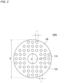
FIG. 2 is a schematic top view of a first insulatingplate 100A according to one embodiment of the present disclosure. The outline of the first insulatingplate 100A inFIG. 2 is circular. The first insulatingplate 100 has a circularfirst hole 110 in the center. In addition, the first insulatingplate 100 has a plurality(48) ofsecond holes 120 around thefirst hole 110. The shape formed by thefirst hole 110 and the plurality ofsecond holes 120 as a whole (i.e., the shape of the aperture) is a shape of rotational symmetry. The aperture of the first insulatingplate 100A has a property (four-fold symmetry) that overlaps with itself when rotated by 360/4°. Note that the number of thesecond holes 110 is not limited to 48, and may be, for example, any number selected from 4 to 100 or 12 to 60. The rotational symmetry is not limited to three-fold symmetry, and may be any one selected from two- to ten-fold symmetry or three- to eight-fold symmetry. - The aperture rate of the first insulating
plate 100A is, for example, 30% or more. That is, the ratio of a sum of the area of the first hole 110 (area of a circle with a diameter d) and the total area of the plurality (48) of second holes 120 (total area of circles each with a diameter i) to the area surrounded by the outline contour (area of a circle with an outer diameter D) of an orthographic projection D0 of the first insulatingplate 100A from the direction normal to the principal surface of the first insulating plate 10A is 30% or more. - The opening area per one of the
second holes 120 is sufficiently smaller than the opening area of the first hole. The opening area per one of thesecond holes 120 is 5% to 20% of the opening area of the first hole, and is 3 mm2 to 17 mm2. In the aperture rate, the proportion occupied by thefirst hole 110 only is 3% to 20%. -
FIG. 3 is a schematic top view of a first insulatingplate 100B according to one embodiment of the present disclosure. The outline of the first insulatingplate 100B inFIG. 3 is circular. The first insulatingplate 100B has, in the center, afirst hole 110B having groove-like portions extending radially in six directions (having a star shape). In addition, the first insulatingplate 100B has a plurality (six) ofsecond holes 120B around thefirst hole 110B. The sixsecond holes 120B are provided radially so as to correspond respectively to the six groove-like portions of thefirst hole 110B. The first insulatingplate 110B is constituted of six fan-shaped portions and linking portions each linking adjacent fan-shaped portions. The number of circular sectors is not limited to six, and may be, for example, any number selected from three to ten. - The shape formed by the
first hole 110B and the plurality ofsecond holes 120B as a whole (i.e., the shape of the aperture) is a shape of rotational symmetry. The aperture of the first insulatingplate 100B has a property (six-fold symmetry) that overlaps with itself when rotated by 360/6°. - The aperture rate of the first insulating
plate 100B is 30% or more. That is, the ratio of a sum of the area of thefirst hole 110B and the total area of the plurality (six) ofsecond holes 120B (total area of through-grooves) to the area surrounded by the outline contour (area of a circle with an outer diameter D) of an orthographic projection D0 of the first insulatingplate 100B from the direction normal to the principal surface of the first insulating plate 10A is 30% or more. - The opening area per one of the
second holes 120B is sufficiently smaller than the opening area of thefirst hole 110B. The opening area per one of thesecond holes 120B is 20% to 50% of the opening area of thefirst hole 110B, and is 17 mm2 to 42 mm2. In the aperture rate, the proportion occupied by thefirst hole 110B only is 20% to 50%. - In the following, a nonaqueous electrolyte secondary battery according to the present disclosure will be specifically described for each constituent element with reference to
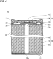
FIG. 4 . - A nonaqueous electrolyte secondary battery according to the present embodiment includes a wound electrode group, a nonaqueous electrolyte, a cylindrical battery case housing them, a sealing body sealing the opening of the battery case, a first insulating plate disposed between the electrode group and the bottom of the battery case, and a second insulating plate disposed between the electrode group and the sealing body. The sealing body includes an air vent valve.
-
FIG. 4 is a schematic longitudinal sectional view of a nonaqueous electrolyte secondary battery according to one embodiment of the present disclosure. The nonaqueous electrolyte secondary battery according to the present embodiment will be specifically described with reference toFIG. 4 , using a lithium-ion secondary battery as an example. - A cylindrical nonaqueous electrolyte secondary battery (hereinafter, battery) 10 includes an
electrode group 18, a nonaqueous electrolyte (not shown), and a battery case (battery can) 22 housing them. Theelectrode group 18 is formed by winding apositive electrode plate 15 and anegative electrode plate 16 with aseparator 17 interposed therebetween. Anannular groove 22a is formed near the open end of the battery can 22. - The opening of the battery can 22 is sealed with a sealing
body 11 having agasket 21 around its periphery. The sealingbody 11 includes avalve body 12, ametal plate 13, and an annular insulatingmember 14 interposed between the outer periphery of thevalve body 12 and the outer periphery of themetal plate 13. Thevalve body 12 and themetal plate 13 are connected to each other at their respective center portions. Apositive electrode lead 15a drawn out from thepositive electrode 15 is connected to themetal plate 13. Thus, thevalve body 12 functions as an external terminal of the positive electrode. Anegative electrode lead 16a drawn out from thenegative electrode 16 is connected (welded) to the inner surface of the bottom of the battery can 22. A first insulatingplate 24 is disposed between one end face of theelectrode group 18 and the bottom of the battery can 22. A second insulatingplate 23 is disposed between the sealingbody 11 and the other end face of theelectrode group 18. - In the present disclosure, it is desirable to set the thickness T of the first insulating plate to 0.05 mm or more and 3 mm or less, and more desirably to 0.1 mm or more and 1 mm or less.
- The outer diameter of the battery is, for example, 18 mm or more and 40 mm or less, and may be 18 mm or more and 26 mm or less. Even when the outer diameter of the battery is 18 mm or more and 26 mm or less, the strength of the first insulating plate is likely to be ensured by setting the thickness T of the first insulating plate to 0.05 mm or more and 3 mm or less. The thickness T of the first insulating plate may be set to 0.1 mm or more and 1 mm or less.
- In the following, the nonaqueous electrolyte secondary battery according to the present disclosure will be more specifically described for each constituent element.
- The positive electrode includes a positive electrode current collector, and a positive electrode mixture layer provided on a surface of the positive electrode current collector. The positive electrode current collector is constituted of a sheet of conductive material. The positive electrode mixture layer is supported on one or both surfaces of the positive electrode current collector. The positive electrode mixture layer is usually a layer or film constituted of a positive electrode mixture. The thickness of the positive electrode mixture layer is, for example, 10 µm to 150 µm per one side of the positive electrode current collector. The positive electrode mixture contains a positive electrode active material as an essential component.
- The positive electrode mixture layer may contain a conductive agent as an optional component. Examples of the conductive agent include carbon-based materials, such as carbon black (CB), acetylene black (AB), Ketjen black, carbon nanotubes (CNTs), graphene, and graphite. These may be used singly or in combination of two or more kinds.
- The positive electrode mixture layer may contain a binder. Examples of the binder include fluorocarbon-based resins, such as polytetrafluoroethylene (PTFE) and polyvinylidene fluoride (PVDF), polyacrylonitrile (PAN), polyimide-based resins, acrylic resins, and polyolefin-based resins. These may be used singly or in combination of two or more.
- As the positive electrode current collector, a non-porous conductive substrate (metal foil, etc.) and a porous conductive substrate (mesh, net, punched sheet, etc.) are used. Examples of the material of the positive electrode current collector include aluminum, aluminum alloy, titanium, and titanium alloy.
- As the positive electrode active material, a lithium-containing composite oxide can be used. The lithium-containing composite oxide may have a layered rock-salt structure. The layered rock-salt structure may belong to, for example, the space group R-3m, the space group C2/m, or the like. In particular, a layered rock-salt structure belonging to the space group R-3m is preferred because of its high capacity and high stability of the crystal structure. The layered rock-salt structure of the lithium-containing composite oxide may include a transition metal layer, a Li layer, and an oxygen layer.
- In view of achieving high capacity, the ratio of Ni (Ni content) in the metal elements other than Li contained in the lithium-containing composite oxide may be set to 50 atom% or more, may be set to 80 atom% or more, and may be set to 90 atom% or more.
- In view of stabilizing the crystal structure of the lithium-containing composite oxide and improving the heat resistance of the battery, the ratio of Co (Co content) in the metal elements other than Li contained in the lithium-containing composite oxide may be set to 0 atom% or more and 16 atom% or less, and may be set to 1.5 atom% or more and 16 atom% or less.
- Likewise, in view of stabilizing the crystal structure of the lithium-containing composite oxide and improving the heat resistance of the battery, the ratio of Al (Al content) in the metal elements other than Li contained in the lithium-containing composite oxide may be set to 0 atom% or more and 18.5 atom% or less, and may be set to 4 atom% or more and 10 atom% or less.
- In view of cost reduction, the ratio of Mn (Mn content) in the metal elements other than Li contained in the lithium-containing composite oxide may be set to 0 atom% or more and 50 atom% or less, and may be set to 0 atom% or more and 30 atom% or less.
- The content ratio of each metal element in the lithium-containing composite oxide is measured by, for example, inductively coupled plasma (ICP) atomic emission spectrometry.
- The lithium-containing composite oxide may be, for example, a composite oxide represented by a general formula LiaNixCoyAlzM1wO2-b, where 0.8 ≤ a ≤ 1.2, 0.80 ≤ x ≤ 0.95, 0.015 ≤ y ≤ 0.16, 0.04 ≤ z ≤ 0.185, 0 ≤ w ≤ 0.145, 0 ≤ b < 0.05, x+y+z+w = 1, and M1 is at least one element selected from Mn, Fe, Ti, Si, Nb, Zr, Mo, and Zn. In this case, M1 is preferably Mn.
- The negative electrode includes at least a negative electrode collector, and may have a negative electrode mixture layer provided on a surface of the negative electrode collector. The negative electrode collector is constituted of a sheet of conductive material. The negative electrode mixture layer is supported on one or both surfaces of the negative electrode collector. The negative electrode mixture layer is usually a layer or film constituted of a negative electrode mixture. The thickness of the negative electrode mixture layer is, for example, 10 µm to 150 µm per one side of the negative electrode current collector. The negative electrode mixture contains a negative electrode active material as an essential component, and may contain a binder, a conductive agent, a thickener, and the like as optional components. Known materials can be used as the binder, the conductive agent, and the thickener.
- The negative electrode active material includes a material that electrochemically absorbs and releases lithium ions, lithium metal, lithium alloy, and the like. As a material that electrochemically absorbs and releases lithium ions, a carbon material, an alloy-type material, and the like are used. Examples of the carbon material include graphite, graphitizable carbon (soft carbon), and non-graphitizable carbon (hard carbon). In particular, graphite is preferable because of its excellent stability during charging and discharging, and small irreversible capacity. The alloy-type material is a material that contains at least one metal capable of forming an alloy with lithium. As such a material, silicon, tin, silicon alloy, tin alloy, a silicon compound, and the like may be used. Silicon oxide, tin oxide, and the like may also be used.
- Preferred as an alloy-type material containing silicon is a silicon-containing material containing a lithium-ion conductive phase and silicon phases dispersed in the lithium-ion conductive phase.
- The lithium-ion conductive phase may be, for example, a silicon oxide phase, a silicate phase, a carbon phase, and the like. The major component of the silicon oxide phase (e.g., 95 to 100 mass%) can be silicon dioxide. The silicate phase is preferred in that the irreversible capacity is small. In particular, a silicate phase containing lithium (hereinafter sometimes referred to as a lithium silicate phase) can be preferably used as a lithium-ion conductive phase having high charge-discharge efficiency in the early stage.
- The lithium silicate phase is an oxide phase containing lithium (Li), silicon (Si), and oxygen (O), and may contain other elements. The atomic ratio O/Si of O to Si in the lithium silicate phase is, for example, more than 2 and less than 4. Preferably, the O/Si is more than 2 and less than 3. The atomic ratio Li/Si of Li to Si in the lithium silicate phase is, for example, more than 0 and less than 4. The lithium silicate phase can have a composition represented by a formula: Li2zSiO2+z, where 0 < z < 2. Preferably, z satisfies 0 < z < 1, and more preferably z = 1/2. Examples of the elements other than Li, Si, and O that may be contained in the lithium silicate phase include iron (Fe), chromium (Cr), nickel (Ni), manganese (Mn), copper (Cu), molybdenum (Mo), zinc (Zn), and aluminum (Al).
- The carbon phase can be constituted of, for example, formless carbon with low crystallinity (i.e., amorphous carbon). The formless carbon may be, for example, hard carbon, soft carbon, or others.
- As the negative electrode active material, a silicon-containing material and a carbon material may be used in combination. The silicon-containing material expands and contracts in volume during charging and discharging. Therefore, when the ratio thereof in the negative electrode active material increases, contact failure between the negative electrode active material and the negative electrode current collector tends occur in association with charging and discharging. On the other hand, by using a silicon-containing material and a carbon material in combination, while imparting high capacity to the negative electrode, it is possible to achieve excellent cycle characteristics.
- The ratio of the silicon-containing material to the total of the silicon-containing material and the carbon material is, for example, preferably 0.5 to 15 mass%, more preferably 1 to 10 mass%. This makes it easier to achieve both high capacity and improved cycle characteristics.
- As the negative electrode current collector, a non-porous conductive substrate (metal foil, etc.) and a porous conductive substrate (mesh, net, punched sheet, etc.) are used. Examples of the material of the negative electrode current collector include stainless steel, nickel, nickel alloy, copper, and copper alloy.
- The nonaqueous electrolyte contains a nonaqueous solvent and a solute dissolved in the nonaqueous solvent. The solute includes, for example, a lithium salt. The components of the nonaqueous electrolyte other than the nonaqueous solvent and the solute are additives. The nonaqueous electrolyte includes the already-described sulfur-containing compound as an additive.
- As the nonaqueous solvent, for example, a cyclic carbonic acid ester, a chain carbonic acid ester, a cyclic carboxylic acid ester, a chain carboxylic acid ester, and the like are used. Examples of the cyclic carbonic acid ester include propylene carbonate (PC), ethylene carbonate (EC), and vinylene carbonate (VC). Examples of the chain carbonic acid ester include diethyl carbonate (DEC), ethyl methyl carbonate (EMC), and dimethyl carbonate (DMC). Examples of the cyclic carboxylic acid ester include γ-butyrolactone (GBL), and γ-valerolactone (GVL). Examples of the chain carboxylic acid ester include methyl acetate, ethyl acetate, propyl acetate, methyl propionate (MP), and ethyl propionate (EP). The nonaqueous solvent may be used singly or in combination of two or more kinds.
- As the lithium salt, for example, a lithium salt of a chlorine-containing acid (LiClO4, LiAlCl4, LiB10Cl10, etc.), a lithium salt of a fluorine-containing acid (LiPF6, LiPF2O2, LiBF4, LiSbF6, LiAsF6, LiCF3SO3, LiCF3CO2, etc.), a lithium salt of a fluorine-containing acid imide (LiN(FSO2)2, LiN(CF3SO2)2, LiN(CF3SO2)(C4F9SO2), LiN(C2F5SO2)2, etc.), a lithium halide (LiCl, LiBr, LiI, etc.), and the like can be used. The lithium salt may be used singly or in combination of two or more kinds.
- The lithium salt concentration in the nonaqueous electrolyte may be 1 mol/liter or more and 2 mol/liter or less, and may be 1 mol/liter or more and 1.5 mol/liter or less. By controlling the lithium salt concentration within the above range, an electrolyte solution having excellent ion conductivity and moderate viscosity can be obtained. The lithium salt concentration, however, is not limited to the above.
- It is desirable to interpose a separator between the positive electrode and the negative electrode. The separator is excellent in ion permeability and has moderate mechanical strength and electrically insulating properties. As the separator, a microporous thin film, a woven fabric, a nonwoven fabric, and the like can be used. The material of the separator is preferably a polyolefin, such as polypropylene and polyethylene.
- The present invention will be more specifically described below with reference to Examples and Comparative Examples. The present invention, however, is not limited to the following Examples.
- First, 100 parts by mass of a positive electrode active material (LiNi0.8Co0.15Al0.05O2), 1.7 parts by mass of a binder (polyvinylidene fluoride), and 2.5 parts by weight of a conductive agent (acetylene black) were added into a dispersion medium, and kneaded together, to prepare a positive electrode mixture slurry. Next, the positive electrode mixture slurry was applied onto both surfaces of a positive electrode collector made of aluminum foil, dried, and rolled, to form positive electrode active material layers, followed by cutting into a predetermined size, to obtain a positive electrode.
- First, 100 parts by mass of a negative electrode active material (graphite), 0.6 parts by mass of a binder (styrene butadiene rubber), and 1 part by weight of a thickener (carboxymethyl cellulose) were added into a dispersion medium, and kneaded together, to prepare a negative electrode mixture slurry. Next, the negative electrode mixture slurry was applied onto both surfaces of a negative electrode current collector made of copper foil, dried and rolled, to form negative electrode active material layers, followed by cutting into a predetermined size, to obtain a negative electrode.
- Ethylene carbonate (EC), ethyl methyl carbonate (EMC), and dimethyl carbonate (DMC) were mixed in a volume ratio of 3:3:4. In the resultant mixed solvent, lithium hexafluorophosphate (LiPF6) was dissolved at a concentration of 1.2 mol/L, to prepare a nonaqueous electrolyte. In the nonaqueous electrolyte, 1,3-propene sultone (PRES), which was a sulfur-containing compound, was dissolved at a content ratio of 0.5 mass%.
- With a positive electrode lead attached to an exposed portion of the positive electrode current collector, and a negative electrode lead attached to the negative electrode current collector, the positive electrode and the negative electrode were wound with a polyolefin microporous membrane (separator) interposed therebetween, to prepare an electrode group. The electrode group, together with a first insulating plate (aperture rate 35%, number of second holes 48) as shown in
FIG. 2 placed on the lower end face, was inserted into a battery can, and the negative electrode lead was resistance welded to the bottom of the battery can. The battery can used here was an iron can having an inner surface plated with nickel. - The opening area per one of the
second holes 120B was 8% of the opening area of thefirst hole 110B, and was 7 mm2. In the aperture rate, the proportion occupied by thefirst hole 110B only was 7%. - A disc-shaped second insulating plate made of glass fibers impregnated with phenolic resin was placed on the upper end face of the electrode group, and then, an annular groove was formed near the open end of the battery can. The thickness T of the first insulating plate was 0.2 mm.
- Next, a positive electrode lead was connected to the metal plate of the safety mechanism included in a sealing body, and after the nonaqueous electrolyte was injected into the iron battery can, the sealing body was supported via a gasket in an annular groove formed in the battery can. The open end of the battery can was crimped onto the periphery of the sealing body, to complete a lithium-ion secondary battery (battery A1).
- In a 25 °C environment, a constant-current discharging was performed at a current of 0.2C from a charged state until the voltage of the nonaqueous electrolyte secondary battery reached 2.5 V. Thereafter, with the positive electrode and the negative electrode electrically connected to each other via a resistor of 1 kΩ, the battery was left to stand at 60 °C for 34 days, to be in an over-discharged state. The battery voltage (OCV) after 34 days is shown in Table 1.
[Table 1] battery first insulating plate aperture rate (%) nonaqueous electrolyte OCV in over-discharged state (V) sulfur-containing compound content (mass%) A1 35 PRES 0.5 0.134 A2 35 LiFSI 4.1 0.129 B1 7 without - 0.223 B2 7 PRES 0.5 0.031 B3 7 LiFSI 4.1 0.000 B4 35 without - 0.225 - A battery A2 of Example 2 was fabricated and evaluated in the same manner as in Example 1, except that 1,3-propene sultone (PRES) was not added to the nonaqueous electrolyte, and lithium hexafluorophosphate (LiPF6) and lithium bisfluorosulfonylimide (LiN(FSO2)2) (LiFSI) were dissolved in the nonaqueous electrolyte at a concentration of 0.9 mol/L and 0.3 mol/L, respectively.
- A battery B1 of Comparative Example 1 was fabricated and evaluated in the same manner as in Example 1, except that a first insulating plate having only the first hole in the center and an aperture rate of 7% (i.e., less than 10%) was used, and 1,3-propene sultone (PRES) was not added to the nonaqueous electrolyte.
- A battery B2 of Comparative Example 2 was fabricated and evaluated in the same manner as in Example 1, except that a first insulating plate having only the first hole in the center and an aperture rate of 7% (i.e., less than 10%) was used.
- A battery B3 of Comparative Example 3 was fabricated and evaluated in the same manner as in Example 2, except that a first insulating plate having only the first hole in the center and an aperture rate of 7% (i.e., less than 10%) was used.
- A battery B4 of Comparative Example 4 was fabricated and evaluated in the same manner as in Example 1, except that 1,3-propene sultone (PRES) was not added to the nonaqueous electrolyte.
- Table 1 shows that when the nonaqueous electrolyte contained no sulfur-containing compound, the OCV of the battery was maintained relatively high, regardless of the form of the first insulating plate. On the other hand, when the nonaqueous electrolyte contained a sulfur-containing compound, the OCV of the battery was considerably changed depending on the form of the first insulating plate. Specifically, in Comparative Examples 2 and 3, in which the aperture rate of the first insulating plate was less than 10%, the OCV dropped to 0.031 V or 0 V, whereas in Examples 1 and 2, in which the aperture rate of the first insulating plate was 10% or more, the OCV was maintained at 0.134 V or 0.129 V.
- The present disclosure includes embodiments additionally noted below.
- (1) A nonaqueous electrolyte secondary battery, comprising:
- a wound electrode group;
- a nonaqueous electrolyte;
- a battery case having a cylindrical shape and housing the electrode group and the nonaqueous electrolyte;
- a sealing body sealing an opening of the battery case; and
- an insulating plate disposed between the electrode group and a bottom of the battery case, wherein
- the nonaqueous electrolyte contains a sulfur-containing compound,
- the insulating plate has an aperture, and
- an aperture rate of the insulating plate is 10% or more.
- (2) A nonaqueous electrolyte secondary battery, comprising:
- a wound electrode group;
- a nonaqueous electrolyte;
- a battery case having a cylindrical shape and housing the electrode group and the nonaqueous electrolyte;
- a sealing body sealing an opening of the battery case; and
- an insulating plate disposed between the electrode group and a bottom of the battery case, wherein
- the nonaqueous electrolyte contains a sulfur-containing compound,
- the insulating plate has an aperture, and
- the aperture has a plurality of mutually independent regions.
- (3) The nonaqueous electrolyte secondary battery according to the above (1) or (2), wherein the aperture includes a first hole provided in a center of the insulating plate.
- (4) The nonaqueous electrolyte secondary battery according to any one of the above (1) to (3), wherein the aperture further includes at least one second hole which is different from the first hole.
- (5) The nonaqueous electrolyte secondary battery according to any one of the above (1) to (4), wherein
- a plurality of the second holes are provided around the first hole, and
- a shape of the aperture is a shape of rotational symmetry.
- (6) The nonaqueous electrolyte secondary battery according to any one of the above (1) to (5), wherein a shape of each of the second holes is a slit-like shape.
- (7) The nonaqueous electrolyte secondary battery according to any one of the above (1) to (6), wherein a shape of each of the second holes is a spot-like shape.
- (8) The nonaqueous electrolyte secondary battery according to any one of the above (1) to (7), wherein the number of the second holes is 6 or more.
- (9) The nonaqueous electrolyte secondary battery according to any one of the above (1) to (8), wherein an aperture rate per one of the second holes is smaller than an aperture rate of the first hole.
- (10) The nonaqueous electrolyte secondary battery according to any one of the above (1) to (9), wherein a content ratio of the sulfur-containing compound in the nonaqueous electrolyte is 0.25 mass% or more and 10 mass% or less.
- (11) The nonaqueous electrolyte secondary battery according to any one of the above (1) to (10), wherein the sulfur-containing compound has one or more sulfonyl groups.
- (12) The nonaqueous electrolyte secondary battery according to any one of the above (1) to (11), wherein the sulfur-containing compound has one or more fluorosulfonyl groups.
- (13) The nonaqueous electrolyte secondary battery according to any one of the above (1) to (12), wherein the sulfur-containing compound has an unsaturated bond.
- (14) The nonaqueous electrolyte secondary battery according to any one of the above (1) to (13), wherein the sulfur-containing compound includes a cyclic sulfonic acid ester.
- The present disclosure is applicable to nonaqueous electrolyte secondary batteries, such as lithium-ion secondary batteries. According to the present disclosure, it is possible to suppress the drop in open circuit voltage (OCV) of the battery in an over-discharged state.
- Although the present invention has been described in terms of the presently preferred embodiments, it is to be understood that such disclosure is not to be interpreted as limiting. Various alterations and modifications will no doubt become apparent to those skilled in the art to which the present invention pertains, after having read the above disclosure. Accordingly, it is intended that the appended claims be interpreted as covering all alterations and modifications as fall within the true spirit and scope of the invention.
- 10: nonaqueous electrolyte secondary battery, 11: sealing body, 12: valve body, 13: metal plate, 14: insulating member, 15: positive electrode, 15a: positive electrode lead, 16: negative electrode, 16a: negative electrode lead, 17: separator, 18: electrode group, 21: gasket, 22: battery can, 22a: annular groove, 23: second insulating plate, 24: first insulating plate, 100, 100A, 100B: first insulating plate, 110, 110B: first hole, 120, 120B: second hole.
Claims (14)
- A nonaqueous electrolyte secondary battery, comprising:a wound electrode group;a nonaqueous electrolyte;a battery case having a cylindrical shape and housing the electrode group and the nonaqueous electrolyte;a sealing body sealing an opening of the battery case; andan insulating plate disposed between the electrode group and a bottom of the battery case, whereinthe nonaqueous electrolyte contains a sulfur-containing compound,the insulating plate has an aperture, andan aperture rate of the insulating plate is 10% or more.
- A nonaqueous electrolyte secondary battery, comprising:a wound electrode group;a nonaqueous electrolyte;a battery case having a cylindrical shape and housing the electrode group and the nonaqueous electrolyte;a sealing body sealing an opening of the battery case; andan insulating plate disposed between the electrode group and a bottom of the battery case, whereinthe nonaqueous electrolyte contains a sulfur-containing compound,the insulating plate has an aperture, andthe aperture has a plurality of mutually independent regions.
- The nonaqueous electrolyte secondary battery according to claim 1 or 2, wherein the aperture includes a first hole provided in a center of the insulating plate.
- The nonaqueous electrolyte secondary battery according to claim 3, wherein the aperture further includes at least one second hole which is different from the first hole.
- The nonaqueous electrolyte secondary battery according to claim 4, whereina plurality of the second holes are provided around the first hole, anda shape of the aperture is a shape of rotational symmetry.
- The nonaqueous electrolyte secondary battery according to claim 5, wherein a shape of each of the second holes is a slit-like shape.
- The nonaqueous electrolyte secondary battery according to claim 5, wherein a shape of each of the second holes is a spot-like shape.
- The nonaqueous electrolyte secondary battery according to claim 5, wherein the number of the second holes is 3 or more.
- The nonaqueous electrolyte secondary battery according to claim 5, wherein an opening area per one of the second holes is smaller than an opening area of the first hole.
- The nonaqueous electrolyte secondary battery according to claim 1 or 2, wherein a content ratio of the sulfur-containing compound in the nonaqueous electrolyte is 0.01 mass% or more and 10 mass% or less.
- The nonaqueous electrolyte secondary battery according to claim 1 or 2, wherein the sulfur-containing compound has one or more sulfonyl groups.
- The nonaqueous electrolyte secondary battery according to claim 1 or 2, wherein the sulfur-containing compound has one or more fluorosulfonyl groups.
- The nonaqueous electrolyte secondary battery according to claim 1 or 2, wherein the sulfur-containing compound has an unsaturated bond.
- The nonaqueous electrolyte secondary battery according to claim 1 or 2, wherein the sulfur-containing compound includes a cyclic sulfonic acid ester.
Applications Claiming Priority (2)
| Application Number | Priority Date | Filing Date | Title |
|---|---|---|---|
| JP2022132724 | 2022-08-23 | ||
| PCT/JP2023/026226 WO2024042918A1 (en) | 2022-08-23 | 2023-07-18 | Non-aqueous electrolyte secondary battery |
Publications (2)
| Publication Number | Publication Date |
|---|---|
| EP4579938A1 true EP4579938A1 (en) | 2025-07-02 |
| EP4579938A4 EP4579938A4 (en) | 2026-01-28 |
Family
ID=90013090
Family Applications (1)
| Application Number | Title | Priority Date | Filing Date |
|---|---|---|---|
| EP23857034.5A Pending EP4579938A4 (en) | 2022-08-23 | 2023-07-18 | Non-aqueous electrolyte secondary battery |
Country Status (5)
| Country | Link |
|---|---|
| US (1) | US20260058220A1 (en) |
| EP (1) | EP4579938A4 (en) |
| JP (1) | JPWO2024042918A1 (en) |
| CN (1) | CN119744478A (en) |
| WO (1) | WO2024042918A1 (en) |
Family Cites Families (9)
| Publication number | Priority date | Publication date | Assignee | Title |
|---|---|---|---|---|
| JP4172061B2 (en) * | 1998-05-13 | 2008-10-29 | 宇部興産株式会社 | Non-aqueous electrolyte secondary battery |
| JP2013134861A (en) * | 2011-12-26 | 2013-07-08 | Sony Corp | Battery, battery pack, electronic apparatus, electric vehicle, power storage device, and electric power system |
| JP5899495B2 (en) | 2011-12-28 | 2016-04-06 | パナソニックIpマネジメント株式会社 | Cylindrical lithium-ion battery |
| WO2016067510A1 (en) * | 2014-10-31 | 2016-05-06 | 三洋電機株式会社 | Battery |
| CN107431178B (en) | 2015-03-27 | 2020-08-11 | 三洋电机株式会社 | Cylindrical battery |
| JP6773942B2 (en) * | 2016-03-07 | 2020-10-21 | エリーパワー株式会社 | Battery lid with terminal and sealed battery |
| JPWO2018123088A1 (en) * | 2016-12-28 | 2019-10-31 | マクセルホールディングス株式会社 | Winding battery |
| JP6753513B2 (en) * | 2017-03-06 | 2020-09-09 | 株式会社村田製作所 | Rechargeable battery |
| KR102268405B1 (en) * | 2018-01-29 | 2021-06-24 | 주식회사 엘지에너지솔루션 | Top Insulator For Secondary Battery And The Method For Manufacturing Thereof |
-
2023
- 2023-07-18 EP EP23857034.5A patent/EP4579938A4/en active Pending
- 2023-07-18 JP JP2024542647A patent/JPWO2024042918A1/ja active Pending
- 2023-07-18 CN CN202380060939.4A patent/CN119744478A/en active Pending
- 2023-07-18 US US19/105,520 patent/US20260058220A1/en active Pending
- 2023-07-18 WO PCT/JP2023/026226 patent/WO2024042918A1/en not_active Ceased
Also Published As
| Publication number | Publication date |
|---|---|
| CN119744478A (en) | 2025-04-01 |
| US20260058220A1 (en) | 2026-02-26 |
| EP4579938A4 (en) | 2026-01-28 |
| WO2024042918A1 (en) | 2024-02-29 |
| JPWO2024042918A1 (en) | 2024-02-29 |
Similar Documents
| Publication | Publication Date | Title |
|---|---|---|
| KR102270869B1 (en) | Additive for nonaqueous electrolyte, nonaqueous electrolyte for lithium secondary battery comprising the same, and lithium secondary battery | |
| US10177413B2 (en) | Lithium ion secondary battery | |
| EP2991138B1 (en) | Method for producing positive electrode active material layer for lithium ion battery, and positive electrode active material layer for lithium ion battery | |
| US8673496B2 (en) | Electrode composition, electrode for lithium secondary battery, method of manufacturing the electrode and lithium secondary battery including the electrode | |
| US20130309570A1 (en) | Positive electrode slurry composition for lithium secondary battery, lithium secondary battery comprising the same and method of making the lithium secondary battery | |
| KR102264733B1 (en) | Non-aqueous electrolyte for lithium secondary battery and lithium secondary battery comprising the same | |
| KR102018756B1 (en) | Electrolyte for lithium secondary battery and lithium secondary battery comprising the same | |
| JP2015144104A (en) | Nonaqueous electrolyte secondary battery | |
| US20210057710A1 (en) | Nonaqueous electrolyte secondary battery | |
| KR102275862B1 (en) | Additive for nonaqueous electrolyte, nonaqueous electrolyte for lithium secondary battery comprising the same, and lithium secondary battery | |
| JP5361029B2 (en) | Positive electrode for non-aqueous electrolyte secondary battery and non-aqueous electrolyte secondary battery | |
| KR20220009894A (en) | Non-aqueous electrolyte solution for lithium secondary battery and lithium secondary battery comprising the same | |
| EP4579851A1 (en) | Non-aqueous electrolyte secondary battery | |
| EP4579938A1 (en) | Non-aqueous electrolyte secondary battery | |
| US12431530B2 (en) | Nonaqueous electrolyte secondary battery | |
| JP2023533050A (en) | Non-aqueous electrolyte for lithium secondary battery and lithium secondary battery containing the same | |
| EP4704170A2 (en) | Electrode for rechargeable lithium battery and rechargeable lithium battery including the same | |
| US8338031B2 (en) | Cathode and lithium battery including the same | |
| EP4037031B1 (en) | Secondary battery | |
| EP4657587A1 (en) | Electrolyte solution for rechargeable lithium battery and rechargeable lithium battery including the same | |
| EP4503225A1 (en) | Electrolyte for rechargeable lithium battery and rechargeable lithium battery including the same | |
| EP4697402A1 (en) | Negative electrode for rechargeable lithium battery and rechargeable lithium battery including same | |
| EP4625585A1 (en) | Nonaqueous electrolyte for secondary battery, and secondary battery | |
| KR20260038385A (en) | Separator for rechargeable lithium battery and rechargeable lithium battery including the same | |
| KR20260022526A (en) | Positive electrode for rechargeable lithium battery, and rechargeable lithium battery including the same |
Legal Events
| Date | Code | Title | Description |
|---|---|---|---|
| STAA | Information on the status of an ep patent application or granted ep patent |
Free format text: STATUS: THE INTERNATIONAL PUBLICATION HAS BEEN MADE |
|
| PUAI | Public reference made under article 153(3) epc to a published international application that has entered the european phase |
Free format text: ORIGINAL CODE: 0009012 |
|
| STAA | Information on the status of an ep patent application or granted ep patent |
Free format text: STATUS: REQUEST FOR EXAMINATION WAS MADE |
|
| 17P | Request for examination filed |
Effective date: 20250303 |
|
| AK | Designated contracting states |
Kind code of ref document: A1 Designated state(s): AL AT BE BG CH CY CZ DE DK EE ES FI FR GB GR HR HU IE IS IT LI LT LU LV MC ME MK MT NL NO PL PT RO RS SE SI SK SM TR |
|
| DAV | Request for validation of the european patent (deleted) | ||
| DAX | Request for extension of the european patent (deleted) | ||
| A4 | Supplementary search report drawn up and despatched |
Effective date: 20260107 |
|
| RIC1 | Information provided on ipc code assigned before grant |
Ipc: H01M 50/593 20210101AFI20251222BHEP Ipc: H01M 10/052 20100101ALI20251222BHEP Ipc: H01M 10/0567 20100101ALI20251222BHEP Ipc: H01M 10/0587 20100101ALI20251222BHEP Ipc: H01M 50/107 20210101ALI20251222BHEP Ipc: H01M 50/152 20210101ALI20251222BHEP Ipc: H01M 50/586 20210101ALI20251222BHEP |