EP4579936A1 - Battery cell group and voltage acquisition method - Google Patents
Battery cell group and voltage acquisition method Download PDFInfo
- Publication number
- EP4579936A1 EP4579936A1 EP23867211.7A EP23867211A EP4579936A1 EP 4579936 A1 EP4579936 A1 EP 4579936A1 EP 23867211 A EP23867211 A EP 23867211A EP 4579936 A1 EP4579936 A1 EP 4579936A1
- Authority
- EP
- European Patent Office
- Prior art keywords
- conductors
- conductor
- connecting plates
- acquisition cable
- group
- Prior art date
- Legal status (The legal status is an assumption and is not a legal conclusion. Google has not performed a legal analysis and makes no representation as to the accuracy of the status listed.)
- Pending
Links
Images



Classifications
-
- H—ELECTRICITY
- H01—ELECTRIC ELEMENTS
- H01M—PROCESSES OR MEANS, e.g. BATTERIES, FOR THE DIRECT CONVERSION OF CHEMICAL ENERGY INTO ELECTRICAL ENERGY
- H01M50/00—Constructional details or processes of manufacture of the non-active parts of electrochemical cells other than fuel cells, e.g. hybrid cells
- H01M50/50—Current conducting connections for cells or batteries
- H01M50/569—Constructional details of current conducting connections for detecting conditions inside cells or batteries, e.g. details of voltage sensing terminals
-
- G—PHYSICS
- G01—MEASURING; TESTING
- G01R—MEASURING ELECTRIC VARIABLES; MEASURING MAGNETIC VARIABLES
- G01R31/00—Arrangements for testing electric properties; Arrangements for locating electric faults; Arrangements for electrical testing characterised by what is being tested not provided for elsewhere
- G01R31/36—Arrangements for testing, measuring or monitoring the electrical condition of accumulators or electric batteries, e.g. capacity or state of charge [SoC]
- G01R31/385—Arrangements for measuring battery or accumulator variables
- G01R31/3865—Arrangements for measuring battery or accumulator variables related to manufacture, e.g. testing after manufacture
-
- G—PHYSICS
- G01—MEASURING; TESTING
- G01R—MEASURING ELECTRIC VARIABLES; MEASURING MAGNETIC VARIABLES
- G01R31/00—Arrangements for testing electric properties; Arrangements for locating electric faults; Arrangements for electrical testing characterised by what is being tested not provided for elsewhere
- G01R31/36—Arrangements for testing, measuring or monitoring the electrical condition of accumulators or electric batteries, e.g. capacity or state of charge [SoC]
- G01R31/389—Measuring internal impedance, internal conductance or related variables
-
- H—ELECTRICITY
- H01—ELECTRIC ELEMENTS
- H01M—PROCESSES OR MEANS, e.g. BATTERIES, FOR THE DIRECT CONVERSION OF CHEMICAL ENERGY INTO ELECTRICAL ENERGY
- H01M10/00—Secondary cells; Manufacture thereof
- H01M10/42—Methods or arrangements for servicing or maintenance of secondary cells or secondary half-cells
- H01M10/48—Accumulators combined with arrangements for measuring, testing or indicating the condition of cells, e.g. the level or density of the electrolyte
- H01M10/482—Accumulators combined with arrangements for measuring, testing or indicating the condition of cells, e.g. the level or density of the electrolyte for several batteries or cells simultaneously or sequentially
-
- H—ELECTRICITY
- H01—ELECTRIC ELEMENTS
- H01M—PROCESSES OR MEANS, e.g. BATTERIES, FOR THE DIRECT CONVERSION OF CHEMICAL ENERGY INTO ELECTRICAL ENERGY
- H01M50/00—Constructional details or processes of manufacture of the non-active parts of electrochemical cells other than fuel cells, e.g. hybrid cells
- H01M50/50—Current conducting connections for cells or batteries
- H01M50/502—Interconnectors for connecting terminals of adjacent batteries; Interconnectors for connecting cells outside a battery casing
- H01M50/503—Interconnectors for connecting terminals of adjacent batteries; Interconnectors for connecting cells outside a battery casing characterised by the shape of the interconnectors
-
- H—ELECTRICITY
- H01—ELECTRIC ELEMENTS
- H01M—PROCESSES OR MEANS, e.g. BATTERIES, FOR THE DIRECT CONVERSION OF CHEMICAL ENERGY INTO ELECTRICAL ENERGY
- H01M50/00—Constructional details or processes of manufacture of the non-active parts of electrochemical cells other than fuel cells, e.g. hybrid cells
- H01M50/50—Current conducting connections for cells or batteries
- H01M50/502—Interconnectors for connecting terminals of adjacent batteries; Interconnectors for connecting cells outside a battery casing
- H01M50/507—Interconnectors for connecting terminals of adjacent batteries; Interconnectors for connecting cells outside a battery casing comprising an arrangement of two or more busbars within a container structure, e.g. busbar modules
-
- G—PHYSICS
- G01—MEASURING; TESTING
- G01R—MEASURING ELECTRIC VARIABLES; MEASURING MAGNETIC VARIABLES
- G01R1/00—Details of instruments or arrangements of the types included in groups G01R5/00 - G01R13/00 and G01R31/00
- G01R1/02—General constructional details
- G01R1/04—Housings; Supporting members; Arrangements of terminals
- G01R1/0408—Test fixtures or contact fields; Connectors or connecting adaptors; Test clips; Test sockets
-
- G—PHYSICS
- G01—MEASURING; TESTING
- G01R—MEASURING ELECTRIC VARIABLES; MEASURING MAGNETIC VARIABLES
- G01R31/00—Arrangements for testing electric properties; Arrangements for locating electric faults; Arrangements for electrical testing characterised by what is being tested not provided for elsewhere
- G01R31/36—Arrangements for testing, measuring or monitoring the electrical condition of accumulators or electric batteries, e.g. capacity or state of charge [SoC]
- G01R31/364—Battery terminal connectors with integrated measuring arrangements
-
- G—PHYSICS
- G01—MEASURING; TESTING
- G01R—MEASURING ELECTRIC VARIABLES; MEASURING MAGNETIC VARIABLES
- G01R31/00—Arrangements for testing electric properties; Arrangements for locating electric faults; Arrangements for electrical testing characterised by what is being tested not provided for elsewhere
- G01R31/36—Arrangements for testing, measuring or monitoring the electrical condition of accumulators or electric batteries, e.g. capacity or state of charge [SoC]
- G01R31/382—Arrangements for monitoring battery or accumulator variables, e.g. SoC
- G01R31/3835—Arrangements for monitoring battery or accumulator variables, e.g. SoC involving only voltage measurements
-
- G—PHYSICS
- G01—MEASURING; TESTING
- G01R—MEASURING ELECTRIC VARIABLES; MEASURING MAGNETIC VARIABLES
- G01R31/00—Arrangements for testing electric properties; Arrangements for locating electric faults; Arrangements for electrical testing characterised by what is being tested not provided for elsewhere
- G01R31/36—Arrangements for testing, measuring or monitoring the electrical condition of accumulators or electric batteries, e.g. capacity or state of charge [SoC]
- G01R31/396—Acquisition or processing of data for testing or for monitoring individual cells or groups of cells within a battery
-
- Y—GENERAL TAGGING OF NEW TECHNOLOGICAL DEVELOPMENTS; GENERAL TAGGING OF CROSS-SECTIONAL TECHNOLOGIES SPANNING OVER SEVERAL SECTIONS OF THE IPC; TECHNICAL SUBJECTS COVERED BY FORMER USPC CROSS-REFERENCE ART COLLECTIONS [XRACs] AND DIGESTS
- Y02—TECHNOLOGIES OR APPLICATIONS FOR MITIGATION OR ADAPTATION AGAINST CLIMATE CHANGE
- Y02E—REDUCTION OF GREENHOUSE GAS [GHG] EMISSIONS, RELATED TO ENERGY GENERATION, TRANSMISSION OR DISTRIBUTION
- Y02E60/00—Enabling technologies; Technologies with a potential or indirect contribution to GHG emissions mitigation
- Y02E60/10—Energy storage using batteries
Definitions
- the present disclosure relates to the technical field of energy storage devices, and in particular to a battery module and a voltage acquisition method.
- battery module is one of the important components of the electric vehicle.
- the battery module further includes flexible flat cables (FFCs) for voltage signals acquisition.
- FFCs flexible flat cables
- the battery module is typically provided with two FFCs, each of the FFCs includes a plurality of conductors arranged in parallel, and all the conductors of each of the FFCs are connected to corresponding cells respectively.
- such mode may lead to an excessively high voltage difference between the corresponding conductors of the two FFCs.
- the excessively high voltage difference can easily cause faults such as electric leakage.
- the present disclosure aims at solving at least one of the technical problems existing in the related art. To this end, the present disclosure proposes a battery module that can reduce the maximum voltage difference between conductors and reduce the risk of electric leakage.
- the present disclosure further proposes a voltage acquisition method.
- the battery module according to the embodiment of the present disclosure at least has the following beneficial effects.
- the first acquisition cable is provided with a vacant position corresponding to at least one of the second conductors
- the second acquisition cable is provided with a vacant position corresponding to at least one of the first conductors
- the voltage of the connecting plate A 1 is 0, the voltage of the connecting plate A 2 is the voltage across a single cell, recorded as V, and the voltage of the connecting plate A 3 is the voltage across two cells, recorded as 2V, and so on, and the voltage of the connecting plate A 9 is the voltage across eight cells, recorded as 8V.
- the second acquisition cable 400 needs to be wired such that the second conductor C 1 is connected to the connecting plate A 9 , the second conductor C 2 is connected to the connecting plate A 8 , the second conductor C 3 is connected to the connecting plate A 6 , the second conductor C 4 is connected to the connecting plate A 4 , and the second conductor C 5 is connected to the connecting plate A 2 (the second conductor C 6 is not connected to the connecting plate and is in a vacant position).
- the voltage difference between the first conductor B 1 and the second conductor C 1 is as high as 8V. As the number of cells 100 is increased, the maximum voltage difference may be further increased. Excessive voltage difference may easily cause the problem of electric leakage.
- the first acquisition cable 300 and the second acquisition cable 400 of the present disclosure are wired in a jump mode, that is, at least one second conductor is arranged between at least one group of adjacent first conductors.
- a jump mode that is, at least one second conductor is arranged between at least one group of adjacent first conductors.
- one or more second conductors are connected to the next connecting plate first, and then other first conductors are wired.
- the maximum voltage difference between the first conductor and the second conductor may be reduced.
- at least one group of adjacent first conductors means that a plurality of pairs of first conductors may each have at least one second conductor arranged therebetween.
- the first conductors and the second conductors are connected to the respective connecting plates in an alternating and sequential manner, which can keep the voltage difference constant to 2V.
- Table 2 First conductor B 1 First conductor B 2 First conductor B 3 First conductor B 4 First conductor B 5 First conductor B 6 First conductor voltage 0 4V 8V 5V IV Vacant Second conductor C 1 Second conductor C 2 Second conductor C 3 Second conductor C 4 Second conductor C 5 Second conductor C 6 Second conductor voltage 2V 6V 7V 3V Vacant Vacant Voltage difference 2V 2V 1V 2V / /
- the total number of first conductors and second conductors is set to be greater than the number of connection points, where the connection points include acquisition points where conductors used as acquisition points are connected to connecting plates, and input points or output points where the conductors used as power lines are connected to the connecting plates, in this way, at least one conductor does not need to be connected to the connecting plate.
- the acquisition solution further includes a judgment step: after a group of first conductor and second conductor are connected to corresponding connecting plates respectively, judging a voltage difference between the first conductor and the second conductor of the group; and if the voltage difference is greater than a set value, disconnecting at least one of the first conductor and the second conductor to form a vacant position so as to avoid generating a voltage difference.
- the judgment step may be an actual detection step, for example, after the conductors are respectively connected to the connecting plates, detecting a voltage difference between corresponding pins of the connector 200 by a detection device.
- the judgment step may also be a simulation detection step, for example, after identifying that the conductors are connected to the connecting plates respectively, inferring the voltage difference between the conductors.
Landscapes
- Chemical & Material Sciences (AREA)
- Chemical Kinetics & Catalysis (AREA)
- Electrochemistry (AREA)
- General Chemical & Material Sciences (AREA)
- Physics & Mathematics (AREA)
- General Physics & Mathematics (AREA)
- Engineering & Computer Science (AREA)
- Manufacturing & Machinery (AREA)
- Battery Mounting, Suspending (AREA)
- Connection Of Batteries Or Terminals (AREA)
Abstract
Description
- This application is filed on the basis of
Chinese patent application No. 202211165532.1 filed on September 23, 2022 - The present disclosure relates to the technical field of energy storage devices, and in particular to a battery module and a voltage acquisition method.
- As an energy supply device for an electric vehicle, battery module is one of the important components of the electric vehicle. In addition to including a plurality of cells, the battery module further includes flexible flat cables (FFCs) for voltage signals acquisition. In the related art, the battery module is typically provided with two FFCs, each of the FFCs includes a plurality of conductors arranged in parallel, and all the conductors of each of the FFCs are connected to corresponding cells respectively. However, such mode may lead to an excessively high voltage difference between the corresponding conductors of the two FFCs. When there are foreign objects between the two FFCs, the excessively high voltage difference can easily cause faults such as electric leakage.
- The present disclosure aims at solving at least one of the technical problems existing in the related art. To this end, the present disclosure proposes a battery module that can reduce the maximum voltage difference between conductors and reduce the risk of electric leakage.
- The present disclosure further proposes a voltage acquisition method.
- The battery module according to a first embodiment of the present disclosure includes:
- a plurality of cells;
- two groups of connecting plates, where the two groups of connecting plates are arranged in parallel, and all the connecting plates of each group distributed in an arrangement direction of the cells;
- a first acquisition cable, which includes a plurality of first conductors arranged in parallel, and
- a second acquisition cable, which is stacked with the first acquisition cable and includes a plurality of second conductors, where in a direction from a head end to a tail end of a first group of connecting plates, and then from a tail end to a head end of a second group of connecting plates, at least some of the first conductors are connected to some of the connecting plates in an arrangement order of the first conductors, at least some of the second conductors are connected to other connecting plates in an arrangement order of the second conductors, and at least one of the second conductors is arranged between at least one group of adjacent first conductors.
- The battery module according to the embodiment of the present disclosure at least has the following beneficial effects.
- By arranging at least one second conductor between at least one group of adjacent first conductors, jump voltage acquisition by the first acquisition cable and the second acquisition cable can be achieved, thereby reducing the maximum voltage difference between corresponding conductors of the first acquisition cable and the second acquisition cable and reducing the risk of electric leakage.
- In other embodiments of the present disclosure, in the direction from the head end to the tail end of the first group of connecting plates, and then from the tail end to the head end of the second group of connecting plates, the first conductors and the second conductors are connected to the respective connecting plates in an alternating and sequential manner.
- In other embodiments of the present disclosure, at least one of the second conductors is arranged between each of the plurality of groups of adjacent first conductors, and/or a plurality of the second conductors are arranged between at least one group of adjacent first conductors.
- In other embodiments of the present disclosure, the first acquisition cable is provided with a vacant position corresponding to at least one of the second conductors, and/or the second acquisition cable is provided with a vacant position corresponding to at least one of the first conductors.
- In other embodiments of the present disclosure, one of the plurality of connecting plates is used as an input terminal of the battery module, and a plurality of adjacent conductors of the same acquisition cable are connected to the input terminal.
- In other embodiments of the present disclosure, the input terminal is connected to a first one of the cells, the input terminal is connected with a first one of the first conductors and a second one of the first conductors, and at least one of the second conductors is arranged between each of a plurality of groups of adjacent first conductors after the first one of the first conductors.
- In other embodiments of the present disclosure, the second acquisition cable is provided with a vacant position corresponding to the second one of the first conductors.
- In other embodiments of the present disclosure, in the direction from the head end to the tail end of the first group of connecting plates, and then from the tail end to the head end of the second group of connecting plates, a last one of the first conductors and a last one of the second conductors are connected to the two adjacent connecting plates in sequence.
- The voltage acquisition method according to a second embodiment of the present disclosure includes:
- preparing a plurality of cells, a plurality of connecting plates, a first acquisition cable, and a second acquisition cable, where the plurality of cells are arranged in sequence, the plurality of connecting plates are divided into two groups, all the connecting plates of each group are distributed in an arrangement direction of the cells, the first acquisition cable includes a plurality of first conductors arranged in parallel, and the second acquisition cable includes a plurality of second conductors arranged in parallel; and
- stacking the first acquisition cable with the second acquisition cable, in a direction from the head end to the tail end of a first group of connecting plates, and then from the tail end to the head end of a second group of connecting plates, connecting at least some of the first conductors to some of the connecting plates in an arrangement order of the first conductors, connecting at least some of the second conductors to other connecting plates in an arrangement order of the second conductors, and arranging at least one of the second conductors between at least one group of adjacent first conductors, so that a voltage difference between each of the first conductors and a corresponding second conductor is lower than a set value.
- In other embodiments of the present disclosure, a sum of the number of the first conductors and the number of the second conductors is greater than the number of connection points, and the method further includes: judging whether the voltage difference is greater than the set value after a group of the first conductors and the second conductors are all connected to the respective connecting plates, and in response to the voltage difference being greater than the set value, forming a vacant position corresponding to at least one of the first conductors and the second conductors.
- Additional aspects and advantages of the present disclosure will be set forth in part in the description which follows, and in part will be obvious from the description, or may be learned by the practice of the present disclosure.
- The present disclosure will be further described below in conjunction with the accompanying drawings and embodiments, where:
-
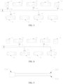
FIG.1 is a top view of a battery module in a first embodiment of the present disclosure; -
FIG.2 is a schematic view ofFIG.1 in which cells and a module housing are hidden; -
FIG.3 is a schematic view of the connection between a first acquisition cable and connecting plates inFIG. 1 ; -
FIG.4 is a schematic view of the connection between the second acquisition cable and the connecting plates inFIG. 1 ; -
FIG.5 is a side view of the connection of the first acquisition cable and the second acquisition cable with a connector inFIG.1 ; -
FIG.6 is a schematic cross-sectional view in an A-A direction inFIG.2 ; -
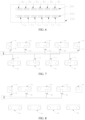
FIG.7 is a schematic view of the connection of a first acquisition cable and a second acquisition cable with connecting plates in a traditional wiring mode; -
FIG.8 is a schematic view of the connection between the first acquisition cable and the connecting plates inFIG.7 ; -
FIG.9 is a schematic view of the connection between the second acquisition cable and the connecting plates inFIG.7 ; -
FIG.10 is a top view of a battery module in a second embodiment of the present disclosure; -
FIG.11 is a schematic view of the connection between a first acquisition cable and connecting plates inFIG. 10 ; -
FIG.12 is a schematic view of the connection between a second acquisition cable and connecting plates inFIG. 10 ; -
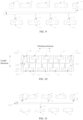
FIG.13 is a schematic view of the connection between a first acquisition cable and connecting plates in a third embodiment of the present disclosure; -
FIG.14 is a schematic view of the connection between a second acquisition cable and connecting plates in a third embodiment of the present disclosure; -
FIG.15 is a schematic view of the connection between a first acquisition cable and connecting plates in a fourth embodiment of the present disclosure; -
FIG.16 is a schematic view of the connection between a second acquisition cable and connecting plates in a fourth embodiment of the present disclosure; -
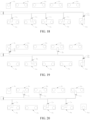
FIG.17 is a schematic view of the connection between a first acquisition cable and connecting plates in a traditional wiring mode; -
FIG.18 is a schematic view of the connection between a second acquisition cable and connecting plates in a traditional wiring mode; -
FIG.19 is a schematic view of the connection between a first acquisition cable and connecting plates in a fifth embodiment of the present disclosure; and -
FIG.20 is a schematic view of the connection between a second acquisition cable and connecting plates in a fifth embodiment of the present disclosure. -
-
cell 100,positive electrode 110,negative electrode 120; -
connector 200; -
first acquisition cable 300, first conductor B1, first conductor B2, first conductor B3, first conductor B4, first conductor B5, first conductor B6; -
second acquisition cable 400, second conductor C1, second conductor C2, second conductor C3, second conductor C4, second conductor C5, second conductor C6; -
input terminal 500; -
output terminal 600; - connecting plate A1, connecting plate A2, connecting plate A3, connecting plate A4, connecting plate A5, connecting plate A6, connecting plate A7, connecting plate A8, connecting plate A9.
- Embodiments of the present disclosure will be described in detail below. Examples of the embodiments are illustrated in the accompanying drawings, where the same or like reference numerals throughout the figures indicate the same or like elements having the same or like functions. The embodiments described below with reference to the accompanying drawings are exemplary and are intended only to explain the present disclosure instead of being construed as limiting the present disclosure.
- In the description of the present disclosure, it should be understood that, descriptions relating to orientation, for example, orientation or positional relationships indicated by "up", "down", "front", "back", "left", "right", etc. are based on the orientation or positional relationships shown in the accompanying drawings, and are to facilitate the description of the present disclosure and simplify the description only, rather than indicating or implying that the device or element referred to must have a specific orientation or be constructed and operated in a specific orientation, and therefore cannot be construed as limiting the present disclosure.
- In the description of the present disclosure, the meaning of "several" is one or more, the meaning of "a plurality of" is two or more, "greater than", "less than", "more than", etc. are to be understood to exclude the given figure, and "above", "below", "within", etc. are understood to include the given figure. If "first" and "second", etc. are referred to, it is only for the purpose of distinguishing technical features, and shall not be understood as indicating or implying relative importance or implying the number of the indicated technical features or implying the sequence of the indicated technical features.
- In the description of the present disclosure, unless otherwise explicitly defined, the words such as "set", "install", and "connect" should be understood in a broad sense, and those of ordinary skills in the art can determine the specific meanings of the above words in the present disclosure in a rational way in combination with the specific contents of the technical solutions.
- In the description of the present disclosure, description with reference to the terms such as "an embodiment", "some embodiments", "illustrative embodiments", "an example", "specific examples", or "some examples" means that the specific features, structures, materials, or characteristics described in connection with that embodiment or example are included in at least one embodiment or example of the present disclosure. In this specification, schematic representations of the above terms do not necessarily refer to the same embodiment or example. Furthermore, the specific features, structures, materials or characteristics described may be combined in a suitable manner in any one or more embodiments or examples.
- The present disclosure proposes a battery module, including a plurality of
cells 100, a plurality of connecting plates, afirst acquisition cable 300, and asecond acquisition cable 400. Thefirst acquisition cable 300 and thesecond acquisition cable 400 can perform jump voltage acquisition, thereby reducing the maximum voltage difference between corresponding conductors of thefirst acquisition cable 300 and thesecond acquisition cable 400 and reducing the faults such as electric leakage. - Referring to
FIG.1 , the battery module includes a plurality ofcells 100. Thecells 100 each may be a rectangular cell as shown in the figure. The plurality ofcells 100 are arranged in sequence in a thickness direction. In some cases, the plurality ofcells 100 are connected in series through a plurality of connecting plates. For example, thecells 100 each includes apositive electrode 110 and anegative electrode 120. Thepositive electrode 110 and thenegative electrode 120 are arranged at both sides of the top of thecell 100 in a length direction of thecell 100. The plurality ofcells 100 are connected in series through the connecting plates. Specifically, thepositive electrodes 110 and thenegative electrodes 120 ofadjacent cells 100 are arranged oppositely, that is, for twoadjacent cells 100, thepositive electrode 110 of onecell 100 and thenegative electrode 120 of theother cell 100 are located at the same side. In this way, thepositive electrode 110 of acell 100 and thenegative electrode 120 of anadjacent cell 100 can be connected through one connecting plate, so that theadjacent cells 100 can be connected in series. By connecting eachcell 100 in this way, all thecells 100 can be connected in series. - It should be noted that in other cases, some
cells 100 of the plurality ofcells 100 are connected in parallel first to form a parallel cell group, and then the parallel cell group is connected in series withother cells 100. In this case, the acquisition cable only needs to acquire the total voltage of the parallel cell group. The plurality ofcells 100 can form one or more parallel cell groups. - Taking all
cells 100 sequentially connected in series as an example, the sequentially connected battery module is as shown inFIG.1 , a plurality of connecting plates are divided into two groups, the two groups of connecting plates are arranged in parallel in a length direction of thecells 100, all the connecting plates of each group are distributed in a thickness direction of thecells 100, and the two groups of connecting plates are arranged in a staggered manner in the thickness direction of thecells 100. For the convenience of description, according to the arrangement order of the connecting plates, the connecting plates are referred to as a connecting plate A1, a connecting plate A2, a connecting plate A3, a connecting plate A4, a connecting plate A5, a connecting plate A6, a connecting plate A7, a connecting plate A8, and a connecting plate A9 in sequence respectively. - The
first acquisition cable 300 includes a plurality of first conductors, and the plurality of first conductors are arranged in parallel in the thickness direction of thecells 100. Thesecond acquisition cable 400 includes a plurality of second conductors, the plurality of second conductors are arranged in the thickness direction of thecells 100, and the number of the first conductors is equal to that of the second conductors. Thefirst acquisition cable 300 and thesecond acquisition cable 400 are both connected to aconnector 200. Theconnector 200 is provided with pins. The number of the pins is greater than or equal to the sum of the number of the first conductors and the number of the second conductors, that is, each conductor is electrically connected to a corresponding pin. - Referring to
FIGS. 2 to 6 ,FIG.2 is a top view of thefirst acquisition cable 300 and thesecond acquisition cable 400 connected to theconnector 200.FIG.3 is a schematic view of the connection between thefirst acquisition cable 300 and each connecting plate.FIG.4 is a schematic view of the connection between thesecond acquisition cable 400 and each connecting plate.FIG.5 is a side view of thefirst acquisition cable 300 and thesecond acquisition cable 400 connected to theconnector 200.FIG.6 is a cross-sectional view in an A-A direction inFIG.2 . Thefirst acquisition cable 300 is stacked with thesecond acquisition cable 400. Taking what is shown in the figure as an example, thefirst acquisition cable 300 is located above thesecond acquisition cable 400, and the first conductors of thefirst acquisition cable 300 are arranged corresponding to the second conductors of thesecond acquisition cable 400. For the convenience of description, the first conductors are referred to as a first conductor B1, a first conductor B2, a first conductor B3, a first conductor B4, a first conductor B5, and a first conductor B6 in sequence respectively, and the second conductors are referred to as a second conductor C1, a second conductor C2, a second conductor C3, a second conductor C4, a second conductor C5, and a second conductor C6 in sequence respectively. - In order to avoid the risk of short circuit caused by cross-wiring connection (the so-called cross-wiring connection means that a conductor is connected to a connecting plate by crossing other conductors, for example, in
FIG.2 , the first conductor B1 is bent toward the connecting plate A2 and jumps over other first conductors, and then is connected to the connecting plate A2), the conductors of thefirst acquisition cable 300 and thesecond acquisition cable 400 need to be connected to the connecting plates in the following mode. In the direction from the head end to the tail end of the first group of connecting plates, and then from the tail end to the head end of the second group of connecting plates, at least some of the first conductors are connected to some of the connecting plates in an arrangement order, and at least some of the second conductors are connected to other connecting plates in an arrangement order, thereby ensuring that each connecting plate is connected with at least one conductor and there is no cross-wiring problem for each conductor. Taking what is shown inFIG.7 to FIG.9 as an example, that is, in a direction from the connecting plate A1, the connecting plate A3, the connecting plate A5, the connecting plate A7, the connecting plate A9, the connecting plate A8, the connecting plate A6, the connecting plate A4 to the connecting plate A2, the first conductor B1, the first conductor B2, the first conductor B3, and the first conductor B4 of different lengths are connected to the connecting plates in sequence. As shown inFIG.7 , the second conductor C1, the second conductor C3, the second conductor C4, and the second conductor C5 of different lengths are also connected to the connecting plates in sequence (the first conductor B5, the first conductor B6 and the second conductor C6 are not connected to the connecting plates and are in the vacant position), thus avoiding the problem of cross-wiring connection. - However, if all the first conductors are connected before the second conductors in sequence, a large voltage difference will occur between some of the first conductors and the respective second conductors. The reason is that all the
cells 100 are connected in series, resulting in different voltages for different connecting plates. Consequently, the conductors connected to the connecting plates also have different voltages. When the voltage difference between a first conductor and a corresponding second conductor is too large, and there are foreign objects between the two, the problem of electric leakage is easy to occur. For example, referring toFIGS. 7 to 9 , the voltage of the connecting plate A1 is 0, the voltage of the connecting plate A2 is the voltage across a single cell, recorded as V, and the voltage of the connecting plate A3 is the voltage across two cells, recorded as 2V, and so on, and the voltage of the connecting plate A9 is the voltage across eight cells, recorded as 8V. On the basis of ensuring that no cross-wiring problem occurs, thefirst acquisition cable 300 needs to be wired such that the first conductor B1 is connected to the connecting plate A1, the first conductor B2 is connected to the connecting plate A3, the first conductor B3 is connected to the connecting plate A5, and the first conductor B4 is connected to the connecting plate A7 (the first conductor B5 and the first conductor B6 are not connected to the connecting plates and are in the vacant position). - The
second acquisition cable 400 needs to be wired such that the second conductor C1 is connected to the connecting plate A9, the second conductor C2 is connected to the connecting plate A8, the second conductor C3 is connected to the connecting plate A6, the second conductor C4 is connected to the connecting plate A4, and the second conductor C5 is connected to the connecting plate A2 (the second conductor C6 is not connected to the connecting plate and is in a vacant position). Then the voltage differences between all first conductors and respective second conductors are shown in Table 1 below:Table 1 First conductor B1 First conductor B2 First conductor B3 First conductor B4 First conductor B5 First conductor B6 First conductor voltage 0 2V 4V 6V Vacant Vacant Second conductor C1 Second conductor C2 Second conductor C3 Second conductor C4 Second conductor C5 Second conductor C6 Second conductor voltage 8V 7V 5V 3V 1V Vacant Voltage 8V 5V 1V 3V / / difference - As can be seen from the above table, the voltage difference between the first conductor B1 and the second conductor C1 is as high as 8V. As the number of
cells 100 is increased, the maximum voltage difference may be further increased. Excessive voltage difference may easily cause the problem of electric leakage. - Based on the above, the
first acquisition cable 300 and thesecond acquisition cable 400 of the present disclosure are wired in a jump mode, that is, at least one second conductor is arranged between at least one group of adjacent first conductors. In other words, after a certain first conductor is connected to a connecting plate, one or more second conductors are connected to the next connecting plate first, and then other first conductors are wired. In this way, the maximum voltage difference between the first conductor and the second conductor may be reduced. It should be noted that the above-mentioned "at least one group of adjacent first conductors" means that a plurality of pairs of first conductors may each have at least one second conductor arranged therebetween. Taking what is shown inFIG.2 to FIG.4 as an example, in some embodiments, in the direction from the head end to the tail end of the first group of connecting plates, and then from the tail end to the head end of the second group of connecting plates, the first conductors and the second conductors are connected to the respective connecting plates in an alternating and sequential manner, which can keep the voltage difference constant to 2V. Specifically, the wiring mode of thefirst acquisition cable 300 is adjusted as follows: the first conductor B1 is connected to the connecting plate A1, the first conductor B2 is connected to the connecting plate A5, the first conductor B3 is connected to the connecting plate A9, the first conductor B4 is connected to the connecting plate A6, and the first conductorB5 is connected to the connecting plate A2. - The wiring mode of the
second acquisition cable 400 is adjusted as follows: the second conductor C1 is connected to the connecting plate A3, the second conductor C2 is connected to the connecting plate A7, the second conductor C3 is connected to the connecting plate A8, and the second conductor C4 is connected to the connecting plate A4. Then the voltage differences between all first conductors and the respective second conductors are shown in Table 2 below:Table 2 First conductor B1 First conductor B2 First conductor B3 First conductor B4 First conductor B5 First conductor B6 First conductor voltage 0 4V 8V 5V IV Vacant Second conductor C1 Second conductor C2 Second conductor C3 Second conductor C4 Second conductor C5 Second conductor C6 Second conductor voltage 2V 6V 7V 3V Vacant Vacant Voltage difference 2V 2V 1V 2V / / - As can be seen from the above table, the maximum voltage difference is constant at 2V, and the maximum voltage difference is significantly reduced.
- In some embodiments, one of the plurality of connecting plates is used as an input terminal of the battery module, and a plurality of adjacent conductors of the same acquisition cable are connected to the input terminal. One of the plurality of connecting plates may be used as an output terminal of the battery module, and a plurality of adjacent conductors of the same acquisition cable are connected to the output terminal. Specifically, according to different usage states of the battery module, the battery module may be provided with an
input terminal 500 and/or anoutput terminal 600. Theinput terminal 500 is connected with at least two adjacent conductors of the same acquisition cable, and theoutput terminal 600 is connected with at least two adjacent conductors of the same acquisition cable, that is, theinput terminal 500 may be connected with at least two adjacent first conductors of thefirst acquisition cable 300, or connected with at least two adjacent second conductors of thesecond acquisition cable 400. It should be noted that theinput terminal 500 or theoutput terminal 600 may be any one of the connecting plates. - Taking what is shown in
FIG. 1 as an example, the battery module is provided with both aninput terminal 500 and anoutput terminal 600, that is, the battery module can achieve input and output independently. Specifically, one of the plurality of connecting plates is used as theinput terminal 500 of the battery module, another one of the connecting plates is used as theoutput terminal 600 of the battery module. Theinput terminal 500 is connected to one electrode of thefirst cell 100, and theoutput terminal 600 is connected to one electrode of thelast cell 100. In this case, theinput terminal 500 is connected with the first conductor B1 and the first conductor B2, theoutput terminal 600 is connected with the first conductor B4 and the first conductor B5, one of the two conductors connected to the input terminal 500 (or the output terminal 600) is used as a power line, and the other is used as an acquisition line. For example, the connecting plate A1 is used as theinput terminal 500 of the battery module, the first conductor B1 is used as the input line of the battery module, the first conductor B2 is used as a voltage acquisition line, the connecting plate A9 is used as theoutput terminal 600 of the battery module, the second conductor C1 is used as an output line of the battery module, and the second conductor C2 is used as a voltage acquisition line. - In other modified embodiments, the battery module may also be provided with only the
input terminal 500 or theoutput terminal 600. In this case, the battery module is used together with other battery modules in series. For example, for two battery modules, the first cell of the former battery module is connected with theinput terminal 500, and the last cell of the latter battery module is connected with theoutput terminal 600. In this case, it is required to connect the last cell of the former battery module with the first cell of the latter battery module in series. - In other modified embodiments, the battery module may not be provided with the
input terminal 500 and theoutput terminal 600. In this case, the battery module is used together with other battery modules in series. For example, for three battery modules, the first cell of the former battery module is connected with theinput terminal 500, the last cell of the latter battery module is connected with theoutput terminal 600, and a middle battery module is not connected with either theinput terminal 500 or theoutput terminal 600. When in use, it is required to connect the last cell of the former battery module with the first cell of the middle battery module in series, and connect the last cell of the middle battery module with the first cell of the latter battery module in series. - When the battery module is provided with both the
input terminal 500 and theoutput terminal 600, with other conditions unchanged, referring toFIGS. 10 to 12 , compared with the embodiment shown inFIG. 1 , the wiring mode of thefirst acquisition cable 300 is adjusted as follows: the first conductor B1 and the first conductor B2 are both connected to the connecting plate A1, the first conductor B3 is connected to the connecting plate A5, the first conductor B4 and the first conductor B5 are both connected to the connecting plate A9, and the first conductor B6 is connected to the connecting plate A4. - The wiring mode of the
second acquisition cable 400 is adjusted as follows: the second conductor C1 is connected to the connecting plate A3, the second conductor C3 is connected to the connecting plate A7, the second conductor C4 is connected to the connecting plate A8, the second conductor C5 is connected to the connecting plate A6, and the second conductor C6 is connected to the connecting plate A2. Then the voltage differences between all first conductors and respective second conductors are shown in Table 3 below:Table 3 First conductor B1 First conductor B2 First conductor B3 First conductor B4 First conductor B5 First conductor B6 First conductor voltage 0 0 4V 8V 8V 3V Second conductor C1 Second conductor C2 Second conductor C3 Second conductor C4 Second conductor C5 Second conductor C6 Second conductor voltage 2V Vacant 6V 7V 5V 1V Voltage difference 2V / 2V 1V 3V 2V - As can be seen from the above table, the maximum voltage difference occurs between the first conductor B5 and the second conductor C5, and the voltage difference is 3V. Compared with the above 8V, the maximum voltage difference is significantly reduced.
- It should be noted that the present disclosure is not limited to the above embodiments. For example, in other embodiments, with other conditions unchanged, referring to
FIGS. 13 and 14 , the wiring mode of thefirst acquisition cable 300 is adjusted as follows: the first conductor B1 and the first conductor B2 are both connected to the connecting plate A1, the first conductor B3 and the first conductor B4 are both connected to the connecting plate A9, the first conductor B5 is connected to the connecting plate A8, and the first conductor B6 is connected to the connecting plate A6. - The wiring mode of the
second acquisition cable 400 is adjusted as follows: the second conductor C1 is connected to the connecting plate A3, the second conductor C3 is connected to the connecting plate A5, the second conductor C4 is connected to the connecting plate A7, the second conductor C5 is connected to the connecting plate A4, and the second conductor C6 is connected to the connecting plate A2. Then the voltage differences between all first conductors and respective second conductors are shown in Table 4 below:Table 4 First conductor B1 First conductor B2 First conductor B3 First conductor B4 First conductor B5 First conductor B6 First conductor voltage 0 0 8V 8V 7V 5V Second conductor C1 Second conductor C2 Second conductor C3 Second conductor C4 Second conductor C5 Second conductor C6 Second conductor voltage 2V Vacant 4V 6V 3V 1V Voltage difference 2V / 4V 2V 4V 4V - As can be seen from the above table, the maximum voltage difference occurs between the first conductor B3 and the second conductor C3, between the first conductor B5 and the second conductor C5, and between the first conductor B6 and the second conductor C6, and the voltage difference is 4V. Compared with the above 8V, the maximum voltage difference is significantly reduced.
- In addition, in this embodiment, only one group of adjacent first conductors have at least one second conductor arranged therebetween.
- For another example, in other embodiments, with other conditions unchanged, referring to
FIGS. 15 and 16 , the wiring mode of thefirst acquisition cable 300 is adjusted as follows: the first conductor B1 and the first conductor B2 are both connected to the connecting plate A1, the first conductor B3 is connected to the connecting plate A3, the first conductor B4 and the first conductor B5 are both connected to the connecting plate A9, and the first conductor B6 is connected to the connecting plate A4. - The wiring mode of the
second acquisition cable 400 is adjusted as follows: the second conductor C1 is connected to the connecting plate A5, the second conductor C3 is connected to the connecting plate A7, the second conductor C4 is connected to the connecting plate A8, the second conductor C5 is connected to the connecting plate A6, and the second conductor C6 is connected to the connecting plate A2. Then the voltage differences between all first conductors and respective second conductors are shown in Table 5 below:Table 5 First conductor B1 First conductor B2 First conductor B3 First conductor B4 First conductor B5 First conductor B6 First conductor voltage 0 0 2V 8V 8V 3V Second conductor C1 Second conductor C2 Second conductor C3 Second conductor C4 Second conductor C5 Second conductor C6 Second conductor voltage 4V Vacant 6V 7V 5V 1V Voltage difference 4V / 4V 1V 3V 2V - As can be seen from the above table, the maximum voltage difference occurs between the first conductor B1 and the second conductor C1, and between the first conductor B3 and the second conductor C3, and the voltage difference is 4V. Compared with the above 8V, the maximum voltage difference is significantly reduced.
- In addition, in this embodiment, each pair of adjacent first conductors have two second conductors arranged therebetween.
- For another example, in other embodiments, the number of
cells 100 may change. Referring toFIGS. 17 and18 , the number ofcells 100 is increased from 8 to 9. When using the traditional wiring mode shown in the figure, the voltage differences between all first conductors and respective second conductors are shown in Table 6 below:Table 6 First conductor B1 First conductor B2 First conductor B3 First conductor B4 First conductor B5 First conductor B6 First conductor voltage 0 0 2V 4V 6V 8V Second conductor C1 Second conductor C2 Second conductor C3 Second conductor C4 Second conductor C5 Second conductor C6 Second conductor voltage 9V 9V 7V 5V 3V 1V Voltage difference 9V 9V 5V 1V 3V 7V - As can be seen from the above table, the voltage difference of 9V occurs between the first conductor B1 and the second conductor C1, and between the first conductor B2 and the second conductor C2, and the maximum voltage difference is further increased.
- With other conditions unchanged, referring to
FIGS. 19 and 20 , the wiring mode of thefirst acquisition cable 300 is adjusted as follows: the first conductor B1 and the first conductor B2 are both connected to the connecting plate A1, the first conductor B3 is connected to the connecting plate A7, the first conductor B4 and the first conductor B5 are both connected to the connecting plate A10, and the first conductor B6 is connected to the connecting plate A4. - The wiring mode of the
second acquisition cable 400 is adjusted as follows: the second conductor C1 is connected to the connecting plate A3, the second conductor C2 is connected to the connecting plate A5, the second conductor C3 is connected to the connecting plate A9, the second conductor C4 is connected to the connecting plate A8, the second conductor C5 is connected to the connecting plate A6, and the second conductor C6 is connected to the connecting plate A2. Then the voltage differences between all first conductors and respective second conductors are shown in Table 7 below:Table 7 First conductor B1 First conductor B2 First conductor B3 First conductor B4 First conductor B5 First conductor B6 First conductor voltage 0 0 6V 9V 9V 3V Second conductor C1 Second conductor C2 Second conductor C3 Second conductor C4 Second conductor C5 Second conductor C6 Second conductor voltage 2V 4V 8V 7V 5V 1V Voltage difference 2V 4V 2V 2V 4V 2V - As can be seen from the above table, the maximum voltage difference occurs between the first conductor B2 and the second conductor C2, and between the first conductor B5 and the second conductor C5, and the voltage difference is 4V. Compared with the above 9V, the maximum voltage difference is significantly reduced.
- It can be understood that for a battery module, the number of
cells 100 may be further increased or decreased, which will not be listed one by one here. - In the battery module of the embodiment of the present disclosure, at least one second conductor is arranged between each of a plurality of groups of adjacent first conductors. For example, in the embodiment shown in
FIG.11 , one second conductor is arranged between the first conductor B2 and the first conductor B3, and one second conductor is also arranged between the first conductor B3 and the first conductor B4. On the other hand, a plurality of second conductors are arranged between each group of first conductors. For example, in the embodiment shown inFIG.15 , two second conductors are arranged between the first conductor B3 and the first conductor B4. The above two solutions may be combined, and the number of the second conductors between each group of adjacent first conductors may be identical. For example, in the embodiment shown inFIG.15 , two second conductors are arranged between the first conductor B3 and the first conductor B4, and two second conductors are also arranged between the conductor B5 and the first conductor B6. The number of the second conductors between each group of adjacent first conductors may be different. For example, in the embodiment shown inFIG.11 , one second conductor is arranged between the first conductor B2 and the first conductor B3, and two second conductors are arranged between the first conductor B5 and the first conductor B6. In this way, flexible wiring of the first conductors and the second conductors can be achieved, thereby reducing the maximum voltage difference. - In other embodiments of the present disclosure, the
first acquisition cable 300 is provided with a vacant position corresponding to at least one second conductor. The so-called vacant position means that the first conductor corresponding to the second conductor is in a disconnected state, for example, the first conductor is not connected to the connecting plate. The vacant position is caused by the inconsistency between the number of conductors and the number of connection points. Taking what is shown inFIG.1 as an example, thefirst acquisition cable 300 and thesecond acquisition cable 400 have a total of 12 conductors, and the battery module has 9 connecting plates, where the connecting plate A2, the connecting plate A3, the connecting plate A4, the connecting plate A5, the connecting plate A6, the connecting plate A7 and the connecting plate A8 all need to be connected to one conductor, so the entire battery module has 9 connection points, and the number of the conductors is 3 more than the number of the connection points. The first conductor B5, the first conductor B6, and the second conductor C6 are not connected to the connecting plate and are in the vacant position. In addition, taking what is shown inFIG.10 as an example, the connecting plate A1 and the connecting plate A9 not only need to acquire voltages, but also need to undertake input and output functions, so each needs to connect two conductors. Therefore, the entire battery module has 11 connection points, and the number of the conductors is 1 more than the number of the connection points, so one vacant position will be generated. It should be noted that according to the difference between the number of the connection points and the number of the conductors, the number of vacant positions may also be set to 2, 3 or others. When the number of the connection points is the same as the number of the conductors, there is no vacant position. In addition, the location of the vacant position is not limited and may be set at any location of thefirst acquisition cable 300 or any location of thesecond acquisition cable 400. - There is no voltage difference between the first conductor in a disconnected state and a corresponding second conductor, and there is no corresponding problem of electric leakage. Therefore, when it is difficult to reduce the voltage difference between a certain group of first conductor and second conductor by jump acquisition, or reducing the voltage difference between the first conductor and the second conductor of this group will cause the voltage difference of another pair of first conductor and second conductor to increase, at least one of the first conductor and the second conductor of this group may be set as a vacant position, thus eliminating the voltage difference.
- Similarly, the
second acquisition cable 400 is provided with a vacant position corresponding to at least one first conductor, and the mode and function are the same as those of thefirst acquisition cable 300. - When the battery module is provided with an
input terminal 500, and theinput terminal 500 is connected to thefirst cell 100, the number of first conductors is recorded as M, and theinput terminal 500 is connected with the first one and the second one of the first conductors. Taking what is shown inFIG. 10 as an example, theinput terminal 500 is connected to the first conductor B1 and the first conductor B2. From the second one of the first conductors to the Mth one of the first conductors, at least two groups of adjacent first conductors may each have at least one second conductor arranged therebetween. For example, taking what is shown inFIG.10 as an example, from the first conductor B2, the first conductor B3, the first conductor B4, the first conductor B5 to the first conductor B6, at least one second conductor is arranged between the first conductor B2 and the first conductor B3, at least one second conductor is arranged between the first conductor B3 and the first conductor B4, and at least one second conductor is arranged between the first conductor B5 and the first conductor B4. In conjunction withFIGS. 10 to 12 ,FIGS. 15 to 18 , andFIGS. 19 to 20 , this arrangement mode is suitable for a battery module with aninput terminal 500, and can significantly reduce the maximum voltage difference between a first conductor and a second conductor. - Based on the above embodiment, the
second acquisition cable 400 is provided with a vacant position corresponding to the second one of the first conductors (for example, the first conductor B2 in the figure). In conjunction withFIGS. 10 to 12 ,FIGS. 15 to 18 , andFIGS. 19 to 20 , when both the first conductor B1 and the first conductor B2 are connected to theinput terminal 500, the voltage thereof is the lowest among the voltages of all the conductors, so a large voltage difference is easily generated. The first conductors and the second conductors are wired in a direction from the head end to the tail end of the first group of connecting plates, and then from the tail end to the head end of the second group of connecting plates. Therefore, the voltage of the second conductor corresponding to the first conductor B2 is inevitably higher than that of the second conductor corresponding to the first conductor B3, that is, a large voltage difference is more likely to occur at the first conductor B2. Based on this, by setting a vacant position in thesecond acquisition cable 400 corresponding to the first conductor B2, the voltage difference at the first conductor B2 can be eliminated. - In some embodiments, in the direction from the head end to the tail end of the first group of connecting plates, and then from the tail end to the head end of the second group of connecting plates, the last one of the first conductors and the last one of the second conductors are connected with two adjacent connecting plates in sequence. According to the aforementioned wiring mode, the last one of the second conductors is fixed in connection position, that is, connected to the connecting plate connected in series between the first cell and the second cell. Therefore, the voltage of the last one of the second conductors is fixed at 1V. Based on this, the closer the last one of the first conductors corresponding thereto is, the lower the voltage difference is. Referring to
FIGS. 10 to 12 , the first conductor B6 is connected to the connecting plate A4, the second conductor C6 is connected to the connecting plate A2, the voltage of the second conductor C6 is 1V, and the voltage of the first conductor B6 is 3V, so the voltage difference can be kept at 2V. If the first conductor B6 is connected to the connecting plate A6 or the connecting plate A8, the voltage difference will be increased to 4V and 6V respectively. Therefore, connecting the last one of the first conductor and the last one of the second conductors to two adjacent connecting plates in sequence can help reduce the voltage difference. - The present disclosure also proposes a voltage acquisition method, including:
- preparing a plurality of
cells 100, a plurality of connecting plates, afirst acquisition cable 300, and asecond acquisition cable 400, where the plurality ofcells 100 are arranged in sequence, the plurality of connecting plates are divided into two groups, all the connecting plates of each group are distributed in an arrangement direction of thecells 100, the plurality ofcells 100 are connected in series through two groups of connecting plates, thefirst acquisition cable 300 includes a plurality of first conductors arranged in parallel, and thesecond acquisition cable 400 includes a plurality of second conductors arranged in parallel; and - stacking the
first acquisition cable 300 with thesecond acquisition cable 400, in a direction from a head end to a tail end of the first group of connecting plates, and then from a tail end to a head end of the second group of connecting plates, connecting at least some of the first conductors to some of the connecting plates in an arrangement order, connecting at least some of the second conductors to other connecting plates in an arrangement order, and arranging at least one second conductor between at least one group of adjacent first conductors, so that the voltage differences between all first conductors and respective second conductors are all less than a set value. - The above acquisition method can be understood in conjunction with
FIGS. 1 to 20 and corresponding embodiments, which will not be described in detail here. - It should be noted that the above set value may be adjusted as needed.
- Based on the above acquisition solution, in some embodiments of the present disclosure, the total number of first conductors and second conductors is set to be greater than the number of connection points, where the connection points include acquisition points where conductors used as acquisition points are connected to connecting plates, and input points or output points where the conductors used as power lines are connected to the connecting plates, in this way, at least one conductor does not need to be connected to the connecting plate.
- The acquisition solution further includes a judgment step: after a group of first conductor and second conductor are connected to corresponding connecting plates respectively, judging a voltage difference between the first conductor and the second conductor of the group; and if the voltage difference is greater than a set value, disconnecting at least one of the first conductor and the second conductor to form a vacant position so as to avoid generating a voltage difference. It should be noted that the judgment step may be an actual detection step, for example, after the conductors are respectively connected to the connecting plates, detecting a voltage difference between corresponding pins of the
connector 200 by a detection device. The judgment step may also be a simulation detection step, for example, after identifying that the conductors are connected to the connecting plates respectively, inferring the voltage difference between the conductors. - In the above embodiment, by setting the vacant position, a corresponding relationship between the first conductor and the second conductor can be flexibly adjusted, and then the maximum voltage difference between the conductors can be controlled.
- The embodiments of the present disclosure are described in detail above in conjunction with the accompanying drawings. However, the present disclosure is not limited to the above embodiments. Within the scope of knowledge possessed by those of ordinary skills in the art, various changes can be made without departing from the purpose of the present disclosure. In addition, the embodiments of the present disclosure and the features in the embodiments may be combined with each other without conflict.
Claims (10)
- A battery module, comprising:a plurality of cells;two groups of connecting plates, wherein the two groups of connecting plates are arranged in parallel, and all the connecting plates of each group distributed in an arrangement direction of the cells;a first acquisition cable, which comprises a plurality of first conductors arranged in parallel, anda second acquisition cable, which is stacked with the first acquisition cable and comprises a plurality of second conductors, wherein in a direction from a head end to a tail end of a first group of connecting plates, and then from a tail end to a head end of a second group of connecting plates, at least some of the first conductors are connected to some of the connecting plates in an arrangement order of the first conductors, at least some of the second conductors are connected to other connecting plates in an arrangement order of the second conductors, and at least one of the second conductors is arranged between at least one group of adjacent first conductors.
- The battery module according to claim 1, wherein in the direction from the head end to the tail end of the first group of connecting plates, and then from the tail end to the head end of the second group of connecting plates, the first conductors and the second conductors are connected to the respective connecting plates in an alternating and sequential manner.
- The battery module according to claim 1, wherein at least one of the second conductors is arranged between each of a plurality of groups of adjacent first conductors, and/or a plurality of the second conductors are arranged between at least one group of adjacent first conductors.
- The battery module according to claim 1, wherein the first acquisition cable is provided with a vacant position corresponding to at least one of the second conductors, and/or the second acquisition cable is provided with a vacant position corresponding to at least one of the first conductors.
- The battery module according to claim 1, wherein one of the plurality of connecting plates is used as an input terminal of the battery module, and a plurality of adjacent conductors of a same acquisition cable are connected to the input terminal.
- The battery module according to claim 5, wherein the input terminal is connected to a first one of the cells, the input terminal is connected with a first one of the first conductors and a second one of the first conductors, and at least one of the second conductors is arranged between each of a plurality of groups of adjacent first conductors after the first one of the first conductors.
- The battery module according to claim 6, wherein the second acquisition cable is provided with a vacant position corresponding to the second one of the first conductors.
- The battery module according to claim 6, wherein in the direction from the head end to the tail end of the first group of connecting plates, and then from the tail end to the head end of the second group of connecting plates, a last one of the first conductors and a last one of the second conductors are connected to the two adjacent connecting plates in sequence.
- A voltage acquisition method, comprising:preparing a plurality of cells, a plurality of connecting plates, a first acquisition cable, and a second acquisition cable, wherein the plurality of cells are arranged in sequence, the plurality of connecting plates are divided into two groups, all the connecting plates of each group are distributed in an arrangement direction of the cells, the first acquisition cable comprises a plurality of first conductors arranged in parallel, and the second acquisition cable comprises a plurality of second conductors arranged in parallel; andstacking the first acquisition cable with the second acquisition cable, in a direction from a head end to a tail end of a first group of connecting plates, and then from a tail end to a head end of a second group of connecting plates, connecting at least some of the first conductors to some of the connecting plates in an arrangement order of the first conductors, connecting at least some of the second conductors to other connecting plates in an arrangement order of the second conductors, and arranging at least one of the second conductors between at least one group of adjacent first conductors, so that a voltage difference between each of the first conductors and a corresponding second conductor is lower than a set value.
- The voltage acquisition method according to claim 9, wherein a sum of the number of the first conductors and the number of the second conductors is greater than the number of connection points, and the method further comprises:judging whether the voltage difference is greater than the set value after a group of the first conductors and the second conductors are all connected to the respective connecting plates, andin response to the voltage difference being greater than the set value, forming a vacant position corresponding to at least one of the first conductors and the second conductors.
Applications Claiming Priority (2)
| Application Number | Priority Date | Filing Date | Title |
|---|---|---|---|
| CN202211165532.1A CN115528391B (en) | 2022-09-23 | 2022-09-23 | Battery pack and voltage collection method |
| PCT/CN2023/114459 WO2024060918A1 (en) | 2022-09-23 | 2023-08-23 | Battery cell group and voltage acquisition method |
Publications (2)
| Publication Number | Publication Date |
|---|---|
| EP4579936A1 true EP4579936A1 (en) | 2025-07-02 |
| EP4579936A4 EP4579936A4 (en) | 2026-03-11 |
Family
ID=84700127
Family Applications (1)
| Application Number | Title | Priority Date | Filing Date |
|---|---|---|---|
| EP23867211.7A Pending EP4579936A4 (en) | 2022-09-23 | 2023-08-23 | BATTERY CELL GROUP AND VOLTAGE SENSING METHOD |
Country Status (4)
| Country | Link |
|---|---|
| EP (1) | EP4579936A4 (en) |
| KR (1) | KR20250007612A (en) |
| CN (1) | CN115528391B (en) |
| WO (1) | WO2024060918A1 (en) |
Families Citing this family (1)
| Publication number | Priority date | Publication date | Assignee | Title |
|---|---|---|---|---|
| CN115528391B (en) * | 2022-09-23 | 2024-06-04 | 欣旺达惠州动力新能源有限公司 | Battery pack and voltage collection method |
Family Cites Families (28)
| Publication number | Priority date | Publication date | Assignee | Title |
|---|---|---|---|---|
| JP4701658B2 (en) * | 2003-10-14 | 2011-06-15 | 日産自動車株式会社 | Battery module and battery pack |
| US8274261B2 (en) * | 2007-07-13 | 2012-09-25 | Black & Decker Inc. | Cell monitoring and balancing |
| WO2010074290A1 (en) * | 2008-12-28 | 2010-07-01 | 株式会社ソリトンシステムズ | Integrated circuit and battery monitoring device utilizing the same |
| JPWO2011043311A1 (en) * | 2009-10-05 | 2013-03-04 | 本田技研工業株式会社 | Battery voltage detector |
| KR101369308B1 (en) * | 2012-04-06 | 2014-03-07 | 인지컨트롤스 주식회사 | Battery for electric vehichle |
| DE102012214231A1 (en) * | 2012-08-10 | 2014-02-13 | Robert Bosch Gmbh | Method for controlling insulation property of housing for battery cell, involves deriving insulation properties from time behavior of electric potentials, and applying control portion of outer or inner sides by utilizing one of potentials |
| KR101698768B1 (en) * | 2013-07-18 | 2017-01-23 | 삼성에스디아이 주식회사 | Battery pack |
| US9831482B2 (en) * | 2013-09-06 | 2017-11-28 | Johnson Controls Technology Company | Battery module lid system and method |
| JP6215358B2 (en) * | 2013-12-25 | 2017-10-18 | 矢崎総業株式会社 | Busbar module and battery pack |
| JP6177352B2 (en) * | 2013-12-25 | 2017-08-09 | 矢崎総業株式会社 | Battery wiring module |
| DE102014118188A1 (en) * | 2014-12-09 | 2016-06-09 | Elringklinger Ag | Cell contacting system for an electrochemical device |
| CN207116619U (en) * | 2017-05-09 | 2018-03-16 | 江苏强劲新能源科技有限公司 | A kind of integrated vehicle lithium battery system signal acquisition wire harness |
| KR102382003B1 (en) * | 2017-06-28 | 2022-04-04 | 삼성전자주식회사 | Method for controlling a plurality of batteries and electronic device thereof |
| CN108417766A (en) * | 2018-05-18 | 2018-08-17 | 中兴高能技术有限责任公司 | Composite sheet, battery modules and battery management system is isolated in harness |
| JP7031509B2 (en) * | 2018-06-20 | 2022-03-08 | 株式会社デンソー | Monitoring device |
| CN108899464B (en) * | 2018-07-02 | 2024-09-10 | 蜂巢能源(武汉)有限公司 | A busbar of a battery module and a battery module |
| US10784495B2 (en) * | 2018-09-19 | 2020-09-22 | Ford Global Technologies, Llc | Systems and methods for providing individual battery cell circuit protection |
| CN209217091U (en) * | 2018-12-07 | 2019-08-06 | 北京国能电池科技股份有限公司 | Voltage acquisition component and battery modules |
| CN109980717B (en) * | 2019-02-25 | 2023-06-16 | 欣旺达电子股份有限公司 | Battery, charger, battery management system, and battery charging method |
| CN210376451U (en) * | 2019-07-19 | 2020-04-21 | 芜湖天量电池系统有限公司 | A structure of a battery module voltage acquisition component |
| KR102381583B1 (en) * | 2020-04-24 | 2022-04-04 | 에너테크인터내셔널 주식회사 | battery module for electric vehicle having monitoring tool |
| CN213340661U (en) * | 2020-10-10 | 2021-06-01 | 湖北亿纬动力有限公司 | Voltage acquisition assembly of battery module and battery module |
| CN214043761U (en) * | 2020-12-21 | 2021-08-24 | 苏州精控能源科技有限公司 | Module voltage acquisition heating integrated device |
| CN114744374B (en) * | 2021-01-07 | 2023-05-05 | 比亚迪股份有限公司 | Battery and battery pack |
| CN215732084U (en) * | 2021-08-25 | 2022-02-01 | 远景动力技术(江苏)有限公司 | Sampling assembly of battery module and battery module |
| CN216870763U (en) * | 2022-01-25 | 2022-07-01 | 宁德时代新能源科技股份有限公司 | Sampling device, battery and electrical equipment |
| CN115084678A (en) * | 2022-06-14 | 2022-09-20 | 广州小鹏汽车科技有限公司 | Circuit board assembly, acquisition module and vehicle |
| CN115528391B (en) * | 2022-09-23 | 2024-06-04 | 欣旺达惠州动力新能源有限公司 | Battery pack and voltage collection method |
-
2022
- 2022-09-23 CN CN202211165532.1A patent/CN115528391B/en active Active
-
2023
- 2023-08-23 WO PCT/CN2023/114459 patent/WO2024060918A1/en not_active Ceased
- 2023-08-23 EP EP23867211.7A patent/EP4579936A4/en active Pending
- 2023-08-23 KR KR1020247039640A patent/KR20250007612A/en active Pending
Also Published As
| Publication number | Publication date |
|---|---|
| CN115528391B (en) | 2024-06-04 |
| EP4579936A4 (en) | 2026-03-11 |
| WO2024060918A1 (en) | 2024-03-28 |
| CN115528391A (en) | 2022-12-27 |
| KR20250007612A (en) | 2025-01-14 |
Similar Documents
| Publication | Publication Date | Title |
|---|---|---|
| DE60128601T2 (en) | Control cabinet for configuring an uninterruptible supply system and backplane wiring used therein | |
| EP2283537B1 (en) | Battery with battery cells and charge compensation apparatus and pole connections which are welded to one another | |
| CN202676841U (en) | Short circuit test structure for adjacent pins of connector | |
| EP4243190B1 (en) | Battery connection module | |
| EP4579936A1 (en) | Battery cell group and voltage acquisition method | |
| US12080913B2 (en) | Wiring harness for energy storage system | |
| WO2012095202A1 (en) | Battery management unit comprising a plurality of monitoring units | |
| KR102743778B1 (en) | battery pack with mesh type busbar connected structure | |
| CN115988738B (en) | Connection methods, systems, and battery packs between BMS and FPC | |
| CN217544839U (en) | Adapters, Batteries and Vehicles for Cell Sampling | |
| CN218548737U (en) | Battery pack with multiple voltage output states and power supply system of electric equipment | |
| EP2612389A2 (en) | High-voltage battery with integrated cell connector | |
| US20220115731A1 (en) | Electric energy storage device and electric tool system | |
| US20210104781A1 (en) | Rechargeable battery monitoring system, battery pack and electric vehicle | |
| CN219458233U (en) | Split-joint branch type communication line and battery management system | |
| WO2020215507A1 (en) | Battery wiring terminal mechanism, power battery system, and electric vehicle | |
| KR20150098721A (en) | Battery pack | |
| CN222691401U (en) | Folding electronic device, charging device and charging system | |
| CN101378160A (en) | Stackable combined connector and connector set | |
| CN223451809U (en) | Energy storage cabinet and power converter | |
| CN223611596U (en) | Voltage divider and simulated battery testing system | |
| CN224035579U (en) | Battery pack insulation withstand voltage testing system | |
| CN212033124U (en) | Connecting and fixing plate for anisotropic soft-package battery | |
| CN220475602U (en) | Electrical power cabinet and electrical equipment | |
| US12315895B2 (en) | Battery having external connector for balance charging and discharging |
Legal Events
| Date | Code | Title | Description |
|---|---|---|---|
| STAA | Information on the status of an ep patent application or granted ep patent |
Free format text: STATUS: THE INTERNATIONAL PUBLICATION HAS BEEN MADE |
|
| PUAI | Public reference made under article 153(3) epc to a published international application that has entered the european phase |
Free format text: ORIGINAL CODE: 0009012 |
|
| STAA | Information on the status of an ep patent application or granted ep patent |
Free format text: STATUS: REQUEST FOR EXAMINATION WAS MADE |
|
| 17P | Request for examination filed |
Effective date: 20250328 |
|
| AK | Designated contracting states |
Kind code of ref document: A1 Designated state(s): AL AT BE BG CH CY CZ DE DK EE ES FI FR GB GR HR HU IE IS IT LI LT LU LV MC ME MK MT NL NO PL PT RO RS SE SI SK SM TR |
|
| DAV | Request for validation of the european patent (deleted) | ||
| DAX | Request for extension of the european patent (deleted) | ||
| A4 | Supplementary search report drawn up and despatched |
Effective date: 20260209 |
|
| RIC1 | Information provided on ipc code assigned before grant |
Ipc: H01M 50/569 20210101AFI20260203BHEP Ipc: H01M 50/503 20210101ALI20260203BHEP Ipc: G01R 31/385 20190101ALI20260203BHEP |