EP4579924A1 - Battery cell, battery and electric device - Google Patents
Battery cell, battery and electric device Download PDFInfo
- Publication number
- EP4579924A1 EP4579924A1 EP23919033.3A EP23919033A EP4579924A1 EP 4579924 A1 EP4579924 A1 EP 4579924A1 EP 23919033 A EP23919033 A EP 23919033A EP 4579924 A1 EP4579924 A1 EP 4579924A1
- Authority
- EP
- European Patent Office
- Prior art keywords
- connecting portion
- sub
- terminal connecting
- terminal
- tab
- Prior art date
- Legal status (The legal status is an assumption and is not a legal conclusion. Google has not performed a legal analysis and makes no representation as to the accuracy of the status listed.)
- Pending
Links
Images




Classifications
-
- H—ELECTRICITY
- H01—ELECTRIC ELEMENTS
- H01M—PROCESSES OR MEANS, e.g. BATTERIES, FOR THE DIRECT CONVERSION OF CHEMICAL ENERGY INTO ELECTRICAL ENERGY
- H01M50/00—Constructional details or processes of manufacture of the non-active parts of electrochemical cells other than fuel cells, e.g. hybrid cells
- H01M50/10—Primary casings; Jackets or wrappings
- H01M50/102—Primary casings; Jackets or wrappings characterised by their shape or physical structure
- H01M50/107—Primary casings; Jackets or wrappings characterised by their shape or physical structure having curved cross-section, e.g. round or elliptic
-
- H—ELECTRICITY
- H01—ELECTRIC ELEMENTS
- H01M—PROCESSES OR MEANS, e.g. BATTERIES, FOR THE DIRECT CONVERSION OF CHEMICAL ENERGY INTO ELECTRICAL ENERGY
- H01M50/00—Constructional details or processes of manufacture of the non-active parts of electrochemical cells other than fuel cells, e.g. hybrid cells
- H01M50/10—Primary casings; Jackets or wrappings
- H01M50/147—Lids or covers
- H01M50/148—Lids or covers characterised by their shape
- H01M50/152—Lids or covers characterised by their shape for cells having curved cross-section, e.g. round or elliptic
-
- H—ELECTRICITY
- H01—ELECTRIC ELEMENTS
- H01M—PROCESSES OR MEANS, e.g. BATTERIES, FOR THE DIRECT CONVERSION OF CHEMICAL ENERGY INTO ELECTRICAL ENERGY
- H01M50/00—Constructional details or processes of manufacture of the non-active parts of electrochemical cells other than fuel cells, e.g. hybrid cells
- H01M50/10—Primary casings; Jackets or wrappings
- H01M50/172—Arrangements of electric connectors penetrating the casing
- H01M50/174—Arrangements of electric connectors penetrating the casing adapted for the shape of the cells
- H01M50/179—Arrangements of electric connectors penetrating the casing adapted for the shape of the cells for cells having curved cross-section, e.g. round or elliptic
-
- H—ELECTRICITY
- H01—ELECTRIC ELEMENTS
- H01M—PROCESSES OR MEANS, e.g. BATTERIES, FOR THE DIRECT CONVERSION OF CHEMICAL ENERGY INTO ELECTRICAL ENERGY
- H01M50/00—Constructional details or processes of manufacture of the non-active parts of electrochemical cells other than fuel cells, e.g. hybrid cells
- H01M50/50—Current conducting connections for cells or batteries
- H01M50/528—Fixed electrical connections, i.e. not intended for disconnection
-
- H—ELECTRICITY
- H01—ELECTRIC ELEMENTS
- H01M—PROCESSES OR MEANS, e.g. BATTERIES, FOR THE DIRECT CONVERSION OF CHEMICAL ENERGY INTO ELECTRICAL ENERGY
- H01M50/00—Constructional details or processes of manufacture of the non-active parts of electrochemical cells other than fuel cells, e.g. hybrid cells
- H01M50/50—Current conducting connections for cells or batteries
- H01M50/531—Electrode connections inside a battery casing
- H01M50/533—Electrode connections inside a battery casing characterised by the shape of the leads or tabs
-
- H—ELECTRICITY
- H01—ELECTRIC ELEMENTS
- H01M—PROCESSES OR MEANS, e.g. BATTERIES, FOR THE DIRECT CONVERSION OF CHEMICAL ENERGY INTO ELECTRICAL ENERGY
- H01M50/00—Constructional details or processes of manufacture of the non-active parts of electrochemical cells other than fuel cells, e.g. hybrid cells
- H01M50/50—Current conducting connections for cells or batteries
- H01M50/531—Electrode connections inside a battery casing
- H01M50/538—Connection of several leads or tabs of wound or folded electrode stacks
-
- H—ELECTRICITY
- H01—ELECTRIC ELEMENTS
- H01M—PROCESSES OR MEANS, e.g. BATTERIES, FOR THE DIRECT CONVERSION OF CHEMICAL ENERGY INTO ELECTRICAL ENERGY
- H01M50/00—Constructional details or processes of manufacture of the non-active parts of electrochemical cells other than fuel cells, e.g. hybrid cells
- H01M50/50—Current conducting connections for cells or batteries
- H01M50/543—Terminals
- H01M50/552—Terminals characterised by their shape
- H01M50/559—Terminals adapted for cells having curved cross-section, e.g. round, elliptic or button cells
-
- H—ELECTRICITY
- H01—ELECTRIC ELEMENTS
- H01M—PROCESSES OR MEANS, e.g. BATTERIES, FOR THE DIRECT CONVERSION OF CHEMICAL ENERGY INTO ELECTRICAL ENERGY
- H01M50/00—Constructional details or processes of manufacture of the non-active parts of electrochemical cells other than fuel cells, e.g. hybrid cells
- H01M50/50—Current conducting connections for cells or batteries
- H01M50/543—Terminals
- H01M50/564—Terminals characterised by their manufacturing process
- H01M50/567—Terminals characterised by their manufacturing process by fixing means, e.g. screws, rivets or bolts
-
- H—ELECTRICITY
- H01—ELECTRIC ELEMENTS
- H01M—PROCESSES OR MEANS, e.g. BATTERIES, FOR THE DIRECT CONVERSION OF CHEMICAL ENERGY INTO ELECTRICAL ENERGY
- H01M50/00—Constructional details or processes of manufacture of the non-active parts of electrochemical cells other than fuel cells, e.g. hybrid cells
- H01M50/50—Current conducting connections for cells or batteries
- H01M50/543—Terminals
- H01M50/564—Terminals characterised by their manufacturing process
- H01M50/566—Terminals characterised by their manufacturing process by welding, soldering or brazing
-
- Y—GENERAL TAGGING OF NEW TECHNOLOGICAL DEVELOPMENTS; GENERAL TAGGING OF CROSS-SECTIONAL TECHNOLOGIES SPANNING OVER SEVERAL SECTIONS OF THE IPC; TECHNICAL SUBJECTS COVERED BY FORMER USPC CROSS-REFERENCE ART COLLECTIONS [XRACs] AND DIGESTS
- Y02—TECHNOLOGIES OR APPLICATIONS FOR MITIGATION OR ADAPTATION AGAINST CLIMATE CHANGE
- Y02E—REDUCTION OF GREENHOUSE GAS [GHG] EMISSIONS, RELATED TO ENERGY GENERATION, TRANSMISSION OR DISTRIBUTION
- Y02E60/00—Enabling technologies; Technologies with a potential or indirect contribution to GHG emissions mitigation
- Y02E60/10—Energy storage using batteries
Definitions
- This application relates to the technical field of batteries, and in particular, to a battery cell, a battery, and an electrical device.
- Electric vehicles have become an important part of the sustainable development of the automobile industry by virtue of energy saving and environmental friendliness. Battery technology is crucial to development of electric vehicles.
- a current collecting component is a component configured to connect an electrode terminal and a tab of an electrode assembly in a battery.
- a terminal connecting portion of the current collecting component is usually designed as bendable.
- the terminal connecting portion of the existing current collecting component is typically a single-layer one-piece structure of limited bendability.
- the thickness of the terminal connecting portion needs to avoid being excessively thick, thereby resulting in a relatively small flow area of the current collecting component, a relatively large internal resistance, and a relatively large temperature rise, and in turn, impairing the safety of the battery.
- this application provides a battery cell, a battery, and an electrical device to alleviate the problem that the safety of the battery is impaired by a small flow area, a large internal resistance, and a large temperature rise of a current collecting component.
- this application provides a battery cell.
- the battery cell includes an electrode assembly, a shell, an electrode terminal, and a current collecting component.
- the electrode assembly includes a tab.
- the shell is configured to accommodate the electrode assembly
- the electrode terminal is disposed on the shell.
- the current collecting component includes a tab connecting portion and a terminal connecting portion.
- the tab connecting portion is configured to be connected to the tab.
- the terminal connecting portion is configured to connect the electrode terminal and the tab connecting portion together.
- the terminal connecting portion includes a plurality of terminal connecting sub-portions stacked in layers. Each terminal connecting sub-portion includes a riveting sub-portion. Any two adjacent riveting sub-portions are fixed together by riveting.
- any two adjacent terminal connecting sub-portions are fixed together by riveting by two adjacent riveting sub-portions, thereby implementing a rivet connection.
- the rivet connection improves the positioning precision during connection of the terminal connecting portion, and avoids the welding process, thereby improving the production efficiency of the current collecting component.
- any two adjacent riveting sub-portions are welded to each other.
- each riveting position between the terminal connecting sub-portions is reinforced by welding.
- the welding reinforcement increases the connection strength between the terminal connecting sub-portions.
- the welding reinforcement increases the flow area of the current collecting component, reduces the internal resistance, reduces the temperature rise, and improves the safety performance of the battery cell.
- the terminal connecting portion is provided with a fixing structure.
- the fixing structure all the riveting sub-portions are stacked in sequence and mated to each other.
- the riveting sub-portions of the terminal connecting sub-portions on adjacent layers are stacked to form a fixing structure, so as to be positioned accurately and easy to align. In addition, no welding process is required, thereby improving the production efficiency of the current collecting component.
- the riveting of the riveting sub-portions of the terminal connecting sub-portions on adjacent layers can reduce burrs.
- the fixing structure is disposed at an end region, close to the electrode terminal, of the terminal connecting portion. In this way, all the terminal connecting sub-portions can be riveted together to form a one-piece terminal connecting portion.
- the fixing structure is disposed at an end region, close to the tab connecting portion, of the terminal connecting portion. In this way, after all the terminal connecting sub-portions are riveted together to form a one-piece terminal connecting portion, the one-piece terminal connecting portion can be conveniently riveted to the tab connecting portion.
- the fixing structure is disposed at an end region, close to the electrode terminal, of the terminal connecting portion, and at an end region, close to the tab connecting portion, of the terminal connecting portion.
- all the terminal connecting sub-portions can be riveted together to form a one-piece terminal connecting portion.
- the one-piece terminal connecting portion can be conveniently riveted to the tab connecting portion.
- a fixing structure is disposed on both opposite ends of the terminal connecting portion, so that the bonding force of the two ends of the one-piece terminal connecting portion is relatively uniform, and the bonding is firmer on the whole.
- the number of the fixing structures is one or more.
- the number of the fixing structures is one, a high positioning precision is ensured during riveting of the terminal connecting sub-portions on any adjacent layers.
- the plurality of fixing structures not only ensures a high positioning precision during riveting of the terminal connecting sub-portions on any adjacent layers, but also improves the connection strength between the terminal connecting sub-portions, thereby preventing easy detachment from each other, and improving the operating stability of the current collecting component.
- a cross-sectional shape of the fixing structure is any one of, but is not limited to, a square, a rectangle, or a circle.
- the cross-sectional shape of the fixing structure is not limited, and may be any one of a square, a rectangle, or a circle, thereby reducing the design difficulty of the terminal connecting portion, and simplifying the manufacture of the current collecting component.
- the terminal connecting portion includes a first main surface and a second main surface arranged opposite to each other along a thickness direction of the terminal connecting portion after being spread out.
- the fixing structure forms a recessed portion on a side at which the first main surface is located, and the fixing structure forms a first protruding portion on the second main surface.
- the fixing structure includes a first protruding portion and a recessed portion, so that misalignment between layers can be avoided during stacking when the terminal connecting portion is formed by riveting, so as to implement accurate positioning and easy alignment. In addition, no welding process is required, thereby improving the production efficiency of the current collecting component.
- the fixing structure includes a first protruding portion and a recessed portion, thereby reducing burrs.
- the tab connecting portion is disposed on one side, close to the second main surface, of the terminal connecting portion.
- the tab connecting portion is provided with a first accommodation portion, and the first protruding portion is accommodated in the first accommodation portion.
- the first protruding portion is accommodated in the first accommodation portion, and can play a positioning role when the terminal connecting portion is connected to the tab connecting portion.
- the terminal connecting portion is fixedly connected to the tab connecting portion by the first protruding portion.
- the first protruding portion is fixedly connected to the first accommodation portion, so that the terminal connecting portion is fixedly connected to the tab connecting portion by the first protruding portion.
- the design in this application improves the positioning precision when the terminal connecting portion is connected to the tab connecting portion, and avoids the welding process, thereby improving the production efficiency of the current collecting component.
- each riveting sub-portion includes a sub-protrusion and a sub-recess.
- Each sub-protrusion protrudes toward the second main surface.
- Each sub-recess is recessed from the first main surface toward the second main surface.
- the sub-protrusion of one riveting sub-portion among two adjacent riveting sub-portions is accommodated in and fixedly connected to the sub-recess of the other riveting sub-portion.
- the sub-protrusion of one of two adjacent terminal connecting sub-portions is riveted to the sub-recess of the other terminal connecting sub-portion, thereby avoiding misalignment between layers during stacking, implementing accurate positioning and easy alignment.
- no welding process is required, thereby improving the production efficiency of the current collecting component.
- the riveting between the sub-protrusion of one of two adjacent terminal connecting sub-portions and the sub-recess of the other terminal connecting sub-portion can reduce burrs.
- bending the plurality of terminal connecting sub-portions to a greater extent can also reduce the space occupied by the current collecting component in the height direction, increase the energy density of the battery cell, and in turn, increase the energy density of the battery, and improve the runtime of the electrical device.
- the term "and/or” merely indicates a relationship between related items, and represents three possible relationships.
- “A and/or B” may represent the following three circumstances: A alone, both A and B, and B alone.
- the character “/” herein generally indicates an "or” relationship between the item preceding the character and the item following the character.
- a direction or a positional relationship indicated by the terms such as “center”, “longitudinal”, “transverse”, “length”, “width”, “thickness”, “up”, “down”, “before”, “after”, “left”, “right”, “vertical”, “horizontal”, “top”, “bottom”, “in”, “out”, “clockwise”, “counterclockwise”, “axial”, “radial”, and “circumferential” is a direction or positional relationship based on the illustration in the drawings, and is merely intended for ease or brevity of description of embodiments of this application, but not intended to indicate or imply that the indicated device or component is necessarily located in the specified direction or constructed or operated in the specified direction. Therefore, such terms are not to be understood as a limitation on embodiments of this application.
- Power batteries are not only used in energy storage power systems such as hydro, thermal, wind, and solar power stations, but also widely used in electric means of transport such as electric bicycles, electric motorcycles, and electric vehicles, and used in many other fields such as military equipment and aerospace.
- the market demand for power batteries keeps soaring with the expansion of the application fields of the power batteries.
- a tab of an electrode assembly is flattened, a current collecting component and the tab are welded together, and the current collecting component is bent and electrically connected to an electrode terminal to output electrical current.
- a terminal connecting portion of the current collecting component needs to avoid being excessively thick. Therefore, the flow area S of the terminal connecting portion is very small.
- the bending process requires the terminal connecting portion to be bent three times.
- the inventor hereof has found through research that the terminal connecting portion of the current collecting component can be designed as a plurality of terminal connecting sub-portions stacked in layers.
- the bonding force between different layers of terminal connecting sub-portions is relatively small, and deformation is more tolerable between layers in a case of bending. In this way, the bendability of the plurality of terminal connecting sub-portions is higher. With the same bendability, the overall thickness of the multilayered terminal connecting portion can be made larger. The flow area of the current collecting component is increased, the internal resistance is reduced, the temperature rise is reduced, and therefore, the safety of the battery is improved.
- the inventor hereof in order to design the terminal connecting portion of the current collecting component into a plurality of terminal connecting sub-portions stacked in layers, the inventor hereof also finds that: the multilayered terminal connecting portion obtained by stacking a material in a plurality of layers and then cutting the stacked layers gives rise to a large number of edge burrs, and, if a plurality of single-layer terminal connecting sub-portions are punched out and then stacked up and welded to obtain a multilayered terminal connecting portion, the sub-portions are unable to be well aligned, and the welding efficiency is relatively low. Neither of the production methods can implement mass production. After in-depth research, the inventor hereof has designed a current collecting component for use in a battery cell.
- the terminal connecting portion of the current collecting component is designed as a plurality of terminal connecting sub-portions stacked in layers.
- the terminal connecting sub-portions on any two adjacent layers are riveted to each other, thereby avoiding generation of burrs, achieving a high positioning precision, and enabling easy alignment.
- no welding process is involved, thereby improving the production efficiency of the terminal connecting portion and facilitating mass production.
- the battery cell disclosed in an embodiment of this application is applicable to an electrical device that uses a battery as a power supply and is applicable to various energy storage systems that use a battery as an energy storage unit.
- the electrical devices may be, but are not limited to, a mobile phone, a tablet, a notebook computer, an electric toy, an electric tool, an electric power cart, an electric vehicle, a ship, a spacecraft, or the like.
- the electric toy may include stationary or mobile electric toys, such as game console, electric car toy, electric ship toy, electric airplane toy, and the like.
- the spacecraft may include airplane, rocket, space shuttle, spaceship, and the like.
- a vehicle 1000 is used as an example of the electrical device according to an embodiment of this application.
- FIG. 1 is a schematic structural diagram of a vehicle 1000 according to some embodiments of this application.
- the vehicle 1000 may be an oil-fueled vehicle, a natural gas vehicle, or a new energy vehicle.
- the new energy vehicle may be a battery electric vehicle, a hybrid electric vehicle, a range-extended electric vehicle, or the like.
- a battery 100 is disposed inside the vehicle 1000.
- the battery 100 may be disposed at the bottom, front, or rear of the vehicle 1000.
- the battery 100 may be configured to supply power to the vehicle 1000.
- the battery 100 may serve as an operating power supply of the vehicle 1000.
- the vehicle 1000 may further include a controller 200 and a motor 300.
- the controller 200 is configured to control the battery 100 to supply power to the motor 300, for example, to meet electrical energy requirements in starting, navigating, or running the vehicle 1000.
- the battery 100 serves not only as an operating power supply of the vehicle 1000, but may also serve as a driving power supply of the vehicle 1000 to provide driving power for the vehicle 1000 in place of or partly in place of fuel oil or natural gas.
- the shell 23 may be a cylindrical structure. An accommodation cavity is formed inside the shell 23, and is configured to accommodate the electrode assembly 25 and an electrolyte solution. The shell 23 is provided with openings at both ends so that the electrode assembly 25 can be placed into the accommodation cavity of the shell 23 through the openings.
- the shell 23 may be made of a metal material such as aluminum or aluminum alloy, or may be made of an insulation material such as plastic or rubber.
Landscapes
- Chemical & Material Sciences (AREA)
- Chemical Kinetics & Catalysis (AREA)
- Electrochemistry (AREA)
- General Chemical & Material Sciences (AREA)
- Engineering & Computer Science (AREA)
- Manufacturing & Machinery (AREA)
- Connection Of Batteries Or Terminals (AREA)
Abstract
Description
- This application relates to the technical field of batteries, and in particular, to a battery cell, a battery, and an electrical device.
- Energy conservation and emission reduction are key to sustainable development of the automobile industry. Electric vehicles have become an important part of the sustainable development of the automobile industry by virtue of energy saving and environmental friendliness. Battery technology is crucial to development of electric vehicles.
- A current collecting component is a component configured to connect an electrode terminal and a tab of an electrode assembly in a battery. In order to reduce the space occupied by the current collecting component in a height direction in the battery, a terminal connecting portion of the current collecting component is usually designed as bendable. However, the terminal connecting portion of the existing current collecting component is typically a single-layer one-piece structure of limited bendability. In order to facilitate bending, the thickness of the terminal connecting portion needs to avoid being excessively thick, thereby resulting in a relatively small flow area of the current collecting component, a relatively large internal resistance, and a relatively large temperature rise, and in turn, impairing the safety of the battery.
- In view of the above problem, this application provides a battery cell, a battery, and an electrical device to alleviate the problem that the safety of the battery is impaired by a small flow area, a large internal resistance, and a large temperature rise of a current collecting component.
- According to a first aspect, this application provides a battery cell. The battery cell includes an electrode assembly, a shell, an electrode terminal, and a current collecting component. The electrode assembly includes a tab. The shell is configured to accommodate the electrode assembly The electrode terminal is disposed on the shell. The current collecting component includes a tab connecting portion and a terminal connecting portion. The tab connecting portion is configured to be connected to the tab. The terminal connecting portion is configured to connect the electrode terminal and the tab connecting portion together. The terminal connecting portion includes a plurality of terminal connecting sub-portions stacked in layers. Each terminal connecting sub-portion includes a riveting sub-portion. Any two adjacent riveting sub-portions are fixed together by riveting.
- In the technical solution of this embodiment of this application, the terminal connecting portion of the current collecting component is designed as a plurality of terminal connecting sub-portions stacked in layers. In contrast to the current collecting component of a single-layer one-piece structure, the bonding force between different layers of terminal connecting sub-portions is relatively small, and deformation is more tolerable between layers in a case of bending. In this way, the bendability of the plurality of terminal connecting sub-portions is higher. With the same bendability, the aggregate thickness of the plurality of terminal connecting sub-portions (that is, the thickness of the terminal connecting portion) can be made larger. The flow area is increased, the internal resistance is reduced, the temperature rise is reduced, and therefore, the safety of the battery is improved. In addition, bending the plurality of terminal connecting sub-portions to a greater extent can also reduce the space occupied by the current collecting component in the height direction, increase the energy density of the battery cell, and in turn, increase the energy density of the battery. In addition, any two adjacent terminal connecting sub-portions are fixed together by riveting by two adjacent riveting sub-portions, thereby implementing a rivet connection. In contrast to a practice in which the terminal connecting portion is formed by welding all the terminal connecting sub-portions together, the rivet connection improves the positioning precision during connection of the terminal connecting portion, and avoids the welding process, thereby improving the production efficiency of the current collecting component.
- In some embodiments, any two adjacent riveting sub-portions are welded to each other. To be specific, each riveting position between the terminal connecting sub-portions is reinforced by welding. On the one hand, the welding reinforcement increases the connection strength between the terminal connecting sub-portions. On the other hand, the welding reinforcement increases the flow area of the current collecting component, reduces the internal resistance, reduces the temperature rise, and improves the safety performance of the battery cell.
- In some embodiments, the terminal connecting portion is provided with a fixing structure. In the fixing structure, all the riveting sub-portions are stacked in sequence and mated to each other.
- In contrast to a practice in which a plurality of single-layer terminal connecting sub-portions are punched out and then stacked up and welded together to form a terminal connecting portion, in these embodiments of this application, the riveting sub-portions of the terminal connecting sub-portions on adjacent layers are stacked to form a fixing structure, so as to be positioned accurately and easy to align. In addition, no welding process is required, thereby improving the production efficiency of the current collecting component. In contrast to a practice in which a multilayered terminal connecting portion is obtained by rolling a material into a plurality of layers and then cutting the rolled layers, in these embodiments of this application, the riveting of the riveting sub-portions of the terminal connecting sub-portions on adjacent layers can reduce burrs.
- In some embodiments, the fixing structure is disposed at an end region, close to the electrode terminal, of the terminal connecting portion. In this way, all the terminal connecting sub-portions can be riveted together to form a one-piece terminal connecting portion.
- In some embodiments, the fixing structure is disposed at an end region, close to the tab connecting portion, of the terminal connecting portion. In this way, after all the terminal connecting sub-portions are riveted together to form a one-piece terminal connecting portion, the one-piece terminal connecting portion can be conveniently riveted to the tab connecting portion.
- In some embodiments, the fixing structure is disposed at an end region, close to the electrode terminal, of the terminal connecting portion, and at an end region, close to the tab connecting portion, of the terminal connecting portion. In this way, on the one hand, all the terminal connecting sub-portions can be riveted together to form a one-piece terminal connecting portion. On the other hand, after all the terminal connecting sub-portions are riveted together to form a one-piece terminal connecting portion, the one-piece terminal connecting portion can be conveniently riveted to the tab connecting portion. Moreover, a fixing structure is disposed on both opposite ends of the terminal connecting portion, so that the bonding force of the two ends of the one-piece terminal connecting portion is relatively uniform, and the bonding is firmer on the whole.
- In some embodiments, the number of the fixing structures is one or more. When the number of the fixing structures is one, a high positioning precision is ensured during riveting of the terminal connecting sub-portions on any adjacent layers. When the number of the fixing structures is plural, the plurality of fixing structures not only ensures a high positioning precision during riveting of the terminal connecting sub-portions on any adjacent layers, but also improves the connection strength between the terminal connecting sub-portions, thereby preventing easy detachment from each other, and improving the operating stability of the current collecting component.
- In some embodiments, a cross-sectional shape of the fixing structure is any one of, but is not limited to, a square, a rectangle, or a circle. The cross-sectional shape of the fixing structure is not limited, and may be any one of a square, a rectangle, or a circle, thereby reducing the design difficulty of the terminal connecting portion, and simplifying the manufacture of the current collecting component.
- In some embodiments, the terminal connecting portion includes a first main surface and a second main surface arranged opposite to each other along a thickness direction of the terminal connecting portion after being spread out. The fixing structure forms a recessed portion on a side at which the first main surface is located, and the fixing structure forms a first protruding portion on the second main surface. The fixing structure includes a first protruding portion and a recessed portion, so that misalignment between layers can be avoided during stacking when the terminal connecting portion is formed by riveting, so as to implement accurate positioning and easy alignment. In addition, no welding process is required, thereby improving the production efficiency of the current collecting component. In addition, the fixing structure includes a first protruding portion and a recessed portion, thereby reducing burrs.
- In some embodiments, the tab connecting portion is disposed on one side, close to the second main surface, of the terminal connecting portion. The tab connecting portion is provided with a first accommodation portion, and the first protruding portion is accommodated in the first accommodation portion. The first protruding portion is accommodated in the first accommodation portion, and can play a positioning role when the terminal connecting portion is connected to the tab connecting portion.
- In some embodiments, the terminal connecting portion is fixedly connected to the tab connecting portion by the first protruding portion. The first protruding portion is fixedly connected to the first accommodation portion, so that the terminal connecting portion is fixedly connected to the tab connecting portion by the first protruding portion. In contrast to a practice in which the terminal connecting portion is connected to the tab connecting portion by welding, the design in this application improves the positioning precision when the terminal connecting portion is connected to the tab connecting portion, and avoids the welding process, thereby improving the production efficiency of the current collecting component.
- In some embodiments, each riveting sub-portion includes a sub-protrusion and a sub-recess. Each sub-protrusion protrudes toward the second main surface. Each sub-recess is recessed from the first main surface toward the second main surface. The sub-protrusion of one riveting sub-portion among two adjacent riveting sub-portions is accommodated in and fixedly connected to the sub-recess of the other riveting sub-portion.
- In contrast to a practice in which a plurality of single-layer terminal connecting sub-portions are punched out and then stacked up and welded together to form a terminal connecting portion, in these embodiments of this application, the sub-protrusion of one of two adjacent terminal connecting sub-portions is riveted to the sub-recess of the other terminal connecting sub-portion, thereby avoiding misalignment between layers during stacking, implementing accurate positioning and easy alignment. In addition, no welding process is required, thereby improving the production efficiency of the current collecting component. In contrast to a practice in which a multilayered terminal connecting portion is obtained by rolling a material into a plurality of layers and then cutting the rolled layers, the riveting between the sub-protrusion of one of two adjacent terminal connecting sub-portions and the sub-recess of the other terminal connecting sub-portion can reduce burrs.
- In some embodiments, the terminal connecting portion is provided with a second accommodation portion, and the tab connecting portion is provided with a second protruding portion. The second protruding portion is accommodated in the second accommodation portion. The second protruding portion is accommodated in the second accommodation portion, thereby improving the positioning accuracy when the terminal connecting portion is connected to the tab connecting portion.
- In some embodiments, the tab connecting portion is fixedly connected to the terminal connecting portion by the second protruding portion. The second protruding portion is fixedly connected to the second accommodation portion, so that the tab connecting portion is fixedly connected to the terminal connecting portion by the second protruding portion. In contrast to a practice in which the tab connecting portion is connected to the terminal connecting portion by welding, the design in this application improves the positioning precision when the tab connecting portion is connected to the terminal connecting portion, and avoids the welding process, thereby improving the production efficiency of the current collecting component.
- In some embodiments, the terminal connecting portion and the tab connecting portion are at least partially welded together. That is, welding is implemented between the terminal connecting portion and the tab connecting portion for reinforcement. On the one hand, the welding increases the flow area of the current collecting component, reduces the internal resistance, reduces the temperature rise, and improves the safety performance of the battery cell. On the other hand, the welding makes the connection firmer between the terminal connecting portion and the tab connecting portion, thereby preventing easy detachment between the two portions, and improving the operating stability of the current collecting component.
- In some embodiments, a weld mark formed between the terminal connecting portion and the tab connecting portion is located in a region outside the fixing structure. The weld mark formed between the terminal connecting portion and the tab connecting portion is located in a region outside the fixing structure, thereby increasing the flow area of the current collecting component on the one hand, reducing the internal resistance, reducing the temperature rise, and improving the safety performance of the battery cell. On the other hand, without destroying the riveting, the positioning of the weld mark makes the connection firmer between the terminal connecting portion and the tab connecting portion, and prevents easy detachment between the two portions, thereby improving the operating stability of the current collecting component.
- In some embodiments, the terminal connecting portion is disposed between the tab connecting portion and the electrode terminal in a bent manner. The terminal connecting portion is disposed between the tab connecting portion and the electrode terminal in a bent manner, thereby reducing the space occupied by the current collecting component in the height direction in the battery cell. On the one hand, this arrangement makes the structure of the battery cell more compact. On the other hand, with the same height of the battery cell, more space can be freed for the electrode assembly, thereby increasing the energy density of the battery cell.
- According to a second aspect, this application provides a battery. The battery includes the battery cell disclosed in any one of the above embodiments.
- In the technical solution of an embodiment of this application, the battery employs the battery cell according to an embodiment of the first aspect. In the battery cell, the terminal connecting sub-portions stacked in layers of the current collecting component are more bendable and not easily breakable, thereby ensuring the operating stability of the battery. In addition, with the same bendability, the aggregate thickness of the plurality of terminal connecting sub-portions can be made larger, thereby increasing the flow area, reducing the internal resistance, and reducing the temperature rise, and in turn, improving the safety of the battery. In addition, bending the plurality of terminal connecting sub-portions to a greater extent can also reduce the space occupied by the current collecting component in the height direction, increase the energy density of the battery cell, and in turn, increase the energy density of the battery.
- According to a third aspect, this application provides an electrical device. The electrical device includes the battery disclosed in any one of the above embodiments. The battery is configured to provide electrical energy.
- In the technical solutions of embodiments of this application, the electrical device employs the battery disclosed in the second aspect according to an embodiment of this application. In a battery cell of the battery, the terminal connecting sub-portions stacked in layers of the current collecting component are more bendable and not easily breakable, thereby ensuring the operating stability of the electrical device. In addition, with the same bendability, the aggregate thickness of the plurality of terminal connecting sub-portions can be made larger, thereby increasing the flow area, reducing the internal resistance, reducing the temperature rise, and in turn, improving the safety of the battery. In addition, bending the plurality of terminal connecting sub-portions to a greater extent can also reduce the space occupied by the current collecting component in the height direction, increase the energy density of the battery cell, and in turn, increase the energy density of the battery, and improve the runtime of the electrical device.
- The above description is merely an overview of the technical solutions of this application. Some specific embodiments of this application are described below illustratively to enable a clearer understanding of the technical solutions of this application, enable implementation of the technical solutions based on the subject-matter hereof, and make the foregoing and other objectives, features, and advantages of this application more evident and comprehensible.
- By reading the following detailed description of exemplary embodiments, a person of ordinary skill in the art becomes clearly aware of various other advantages and benefits. The drawings are merely intended to illustrate the exemplary embodiments, but not to limit this application. In all the drawings, the same reference numeral represents the same component. In the drawings:
-
FIG. 1 is a schematic structural diagram of a vehicle according to some embodiments of this application; -
FIG. 2 is a schematic exploded view of a battery according to some embodiments of this application; -
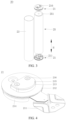
FIG. 3 is a three-dimensional schematic structural diagram of a battery cell according to some embodiments of this application; -
FIG. 4 is a three-dimensional schematic structural diagram of a top cap assembly according to some embodiments of this application; -
FIG. 5 is a schematic exploded view of a top cap assembly according to some embodiments of this application; -
FIG. 6 is a planar schematic structural diagram of a top cap assembly according to some embodiments of this application; -
FIG. 7 is a cross-sectional schematic view of the top cap assembly shown inFIG. 6 and sectioned along a VII-VII line; -
FIG. 8 is a cross-sectional schematic view of the top cap assembly shown inFIG. 6 and sectioned along a VIII-VIII line; -
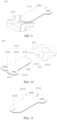
FIG. 9 is a three-dimensional schematic structural diagram of a current collecting component according to some embodiments of this application; -
FIG. 10 is a schematic exploded view of a current collecting component according to some embodiments of this application; -
FIG. 11 is a three-dimensional schematic structural diagram of a terminal connecting portion in a current collecting component according to some embodiments of this application; -
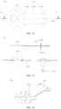
FIG. 12 is a planar schematic structural diagram of a current collecting component according to some embodiments of this application; -
FIG. 13 is a cross-sectional schematic view of the current collecting component shown inFIG. 12 and sectioned along an XIII-XIII line; -
FIG. 14 is a planar schematic structural diagram of a current collecting component according to some embodiments of this application; -
FIG. 15 is a cross-sectional schematic view of the current collecting component shown inFIG. 14 and sectioned along an XV-XV line; and -
FIG. 16 is a three-dimensional schematic structural diagram of a current collecting component according to some embodiments of this application. - List of reference numerals:
-
vehicle 1000; -
battery 100,controller 200,motor 300; -
box 10, first part 11,second part 12; -
battery cell 20,top cap assembly 21,current collecting component 211,tab connecting portion 2111,connection region 21111,weld region 21113, terminal connecting portion2113, first connectingsection 21131, second connectingsection 21133,bent section 21135, fixingstructure 2115,riveting sub-portion 21151,first accommodation portion 2117,second accommodation portion 2118,accommodation sub-portion 21181, second protrudingportion 2119,terminal connecting sub-portion 21137,top cap sheet 212,first insulation piece 213,second insulation piece 214, connectingpiece 215,electrode terminal 216, sealingelement 217;shell 23;electrode assembly 25. - Some embodiments of the technical solutions of this application are described in detail below with reference to the drawings. The following embodiments are merely intended as examples to describe the technical solutions of this application more clearly, but not intended to limit the protection scope of this application.
- Unless otherwise defined, all technical and scientific terms used herein bear the same meanings as what is normally understood by a person skilled in the technical field of this application. The terms used herein are merely intended to describe specific embodiments but not to limit this application. The terms "include" and "contain" and any variations thereof used in the specification, claims, and brief description of drawings of this application are intended as non-exclusive inclusion.
- In the description of some embodiments of this application, the technical terms "first" and "second" are merely intended to distinguish between different items but not intended to indicate or imply relative importance or implicitly specify the number of the indicated technical features, specific order, or order of precedence. In the description of some embodiments of this application, unless otherwise expressly specified, "a plurality of" means two or more.
- Reference to an "embodiment" herein means that a specific feature, structure or characteristic described with reference to this embodiment may be included in at least one embodiment of this application. Reference to this term in different places in the specification does not necessarily represent the same embodiment, nor does it represent an independent or alternative embodiment in a mutually exclusive relationship with other embodiments. A person skilled in the art explicitly and implicitly understands that the embodiments described herein may be combined with other embodiments.
- In the description of embodiments of this application, the term "and/or" merely indicates a relationship between related items, and represents three possible relationships. For example, "A and/or B" may represent the following three circumstances: A alone, both A and B, and B alone. In addition, the character "/" herein generally indicates an "or" relationship between the item preceding the character and the item following the character.
- In the description of embodiments of this application, the term "a plurality of" means two or more (including two). Similarly, "a plurality of groups" means two or more groups (including two groups), and "a plurality of pieces" means two or more pieces (including two pieces).
- In the description of embodiments of this application, a direction or a positional relationship indicated by the terms such as "center", "longitudinal", "transverse", "length", "width", "thickness", "up", "down", "before", "after", "left", "right", "vertical", "horizontal", "top", "bottom", "in", "out", "clockwise", "counterclockwise", "axial", "radial", and "circumferential" is a direction or positional relationship based on the illustration in the drawings, and is merely intended for ease or brevity of description of embodiments of this application, but not intended to indicate or imply that the indicated device or component is necessarily located in the specified direction or constructed or operated in the specified direction. Therefore, such terms are not to be understood as a limitation on embodiments of this application.
- In the description of this application, unless otherwise expressly specified and defined, the technical terms such as "mount", "concatenate", "connect", and "fix" are generic in a broad sense, for example, mean a fixed connection, a detachable connection, or a one-piece configuration; or mean a mechanical connection or an electrical connection; or mean a direct connection or an indirect connection implemented through an intermediary; or mean internal communication between two components or interaction between two components. A person of ordinary skill in the art can understand the specific meanings of the terms in some embodiments of this application according to specific situations.
- Currently, as can be seen from the market trend, the application of power batteries is increasingly extensive. Power batteries are not only used in energy storage power systems such as hydro, thermal, wind, and solar power stations, but also widely used in electric means of transport such as electric bicycles, electric motorcycles, and electric vehicles, and used in many other fields such as military equipment and aerospace. The market demand for power batteries keeps soaring with the expansion of the application fields of the power batteries.
- The inventor hereof has noticed that in a typical battery currently, a tab of an electrode assembly is flattened, a current collecting component and the tab are welded together, and the current collecting component is bent and electrically connected to an electrode terminal to output electrical current. This places a high requirement on the flow capacity of the current collecting component. However, in order to facilitate bending and process welding (welding between the current collecting component and the tab of the electrode assembly), a terminal connecting portion of the current collecting component needs to avoid being excessively thick. Therefore, the flow area S of the terminal connecting portion is very small. In addition, the bending process requires the terminal connecting portion to be bent three times. Consequently, the length L of the terminal connecting portion is relatively large, the internal resistance of the terminal connecting portion is increased as can be deduced from the resistance calculation formula R = ρ × L/S, and the requirements on the flow capacity and the internal resistance of power-type batteries fail to be met.
- To alleviate the problem that the safety of the battery is impaired by a relatively small flow area, a relatively large internal resistance, and a relatively large temperature rise of the current collecting component, the inventor hereof has found through research that the terminal connecting portion of the current collecting component can be designed as a plurality of terminal connecting sub-portions stacked in layers. In contrast to the current collecting component of a single-layer one-piece structure, the bonding force between different layers of terminal connecting sub-portions is relatively small, and deformation is more tolerable between layers in a case of bending. In this way, the bendability of the plurality of terminal connecting sub-portions is higher. With the same bendability, the overall thickness of the multilayered terminal connecting portion can be made larger. The flow area of the current collecting component is increased, the internal resistance is reduced, the temperature rise is reduced, and therefore, the safety of the battery is improved.
- In view of the above factors, in order to design the terminal connecting portion of the current collecting component into a plurality of terminal connecting sub-portions stacked in layers, the inventor hereof also finds that: the multilayered terminal connecting portion obtained by stacking a material in a plurality of layers and then cutting the stacked layers gives rise to a large number of edge burrs, and, if a plurality of single-layer terminal connecting sub-portions are punched out and then stacked up and welded to obtain a multilayered terminal connecting portion, the sub-portions are unable to be well aligned, and the welding efficiency is relatively low. Neither of the production methods can implement mass production. After in-depth research, the inventor hereof has designed a current collecting component for use in a battery cell. The terminal connecting portion of the current collecting component is designed as a plurality of terminal connecting sub-portions stacked in layers. The terminal connecting sub-portions on any two adjacent layers are riveted to each other, thereby avoiding generation of burrs, achieving a high positioning precision, and enabling easy alignment. In addition, no welding process is involved, thereby improving the production efficiency of the terminal connecting portion and facilitating mass production.
- The battery cell disclosed in an embodiment of this application is applicable to an electrical device that uses a battery as a power supply and is applicable to various energy storage systems that use a battery as an energy storage unit. The electrical devices may be, but are not limited to, a mobile phone, a tablet, a notebook computer, an electric toy, an electric tool, an electric power cart, an electric vehicle, a ship, a spacecraft, or the like. The electric toy may include stationary or mobile electric toys, such as game console, electric car toy, electric ship toy, electric airplane toy, and the like. The spacecraft may include airplane, rocket, space shuttle, spaceship, and the like.
- For ease of description in the following embodiments, a
vehicle 1000 is used as an example of the electrical device according to an embodiment of this application. - Referring to
FIG. 1, FIG. 1 is a schematic structural diagram of avehicle 1000 according to some embodiments of this application. Thevehicle 1000 may be an oil-fueled vehicle, a natural gas vehicle, or a new energy vehicle. The new energy vehicle may be a battery electric vehicle, a hybrid electric vehicle, a range-extended electric vehicle, or the like. Abattery 100 is disposed inside thevehicle 1000. Thebattery 100 may be disposed at the bottom, front, or rear of thevehicle 1000. Thebattery 100 may be configured to supply power to thevehicle 1000. For example, thebattery 100 may serve as an operating power supply of thevehicle 1000. Thevehicle 1000 may further include acontroller 200 and amotor 300. Thecontroller 200 is configured to control thebattery 100 to supply power to themotor 300, for example, to meet electrical energy requirements in starting, navigating, or running thevehicle 1000. - In some embodiments of this application, the
battery 100 serves not only as an operating power supply of thevehicle 1000, but may also serve as a driving power supply of thevehicle 1000 to provide driving power for thevehicle 1000 in place of or partly in place of fuel oil or natural gas. - Referring to
FIG. 2, FIG. 2 is an exploded view of abattery 100 according to some embodiments of this application. Thebattery 100 includes abox 10 and abattery cell 20. Thebattery cell 20 is accommodated in thebox 10. Thebox 10 is configured to provide an accommodation space for thebattery cell 20. Thebox 10 may be in various structures. In some embodiments, thebox 10 may include a first part 11 and asecond part 12. The first part 11 and thesecond part 12 fit and cover each other. The first part 11 and thesecond part 12 together define an accommodation space configured to accommodate thebattery cell 20. Thesecond part 12 may be a hollow structure opened at one end. The first part 11 may be a plate-like structure. The first part 11 fits the opening of thesecond part 12 so that the first part 11 and thesecond part 12 together define the accommodation space. Alternatively, both the first part 11 and thesecond part 12 may be hollow structures opened at one side. The opening of the first part 11 fits the opening of thesecond part 12. Definitely, thebox 10 formed by the first part 11 and thesecond part 12 may be in various shapes, such as a cylinder or a cuboid. - The
battery 100 may contain a plurality ofbattery cells 20. The plurality ofbattery cells 20 may be connected in series, parallel, or series-and-parallel pattern. The series-and-parallel pattern means a combination of series connection and parallel connection of the plurality ofbattery cells 20. The plurality ofbattery cells 20 may be directly connected in series, parallel, or series-and-parallel pattern, and then the whole of the plurality ofbattery cells 20 may be accommodated in thebox 10. Alternatively, to make up abattery 100, the plurality ofbattery cells 20 may be connected in series, parallel, or series-and-parallel pattern to form a battery module first, and then a plurality of battery modules are connected in series, parallel, or series-and-parallel pattern to form a whole and accommodated in thebox 10. Thebattery 100 may further include other structures. For example, thebattery 100 may further include a busbar component. The busbar component is configured to implement electrical connection between the plurality ofbattery cells 20. - Each
battery cell 20 may be, but is not limited to, a secondary battery or primary battery; or, may be a lithium-sulfur battery, a sodium-ion battery, or a magnesium-ion battery. Thebattery cell 20 may be in a shape such as a cylinder, a flat body, a cuboid, or other shapes. Thebattery cell 20 is a minimum unit of abattery 100. This application is described by using an example in which thebattery cell 20 is a cylindrical cell. - Referring to
FIG. 3 , which shows abattery cell 20 according to some embodiments of this application, thebattery cell 20 includes: ashell 23, anelectrode assembly 25, anelectrode terminal 216, and acurrent collecting component 211. Theshell 23 is configured to accommodate theelectrode assembly 25. Theelectrode assembly 25 includes atab 251. Theelectrode terminal 216 is disposed on theshell 23. Referring toFIG. 9 and FIG. 10 , thecurrent collecting component 211 includes atab connecting portion 2111 and aterminal connecting portion 2113. Thetab connecting portion 2111 is configured to be connected to thetab 251. Theterminal connecting portion 2113 is configured to connect theelectrode terminal 216 and thetab connecting portion 2111. Referring toFIG. 13 , theterminal connecting portion 2113 includes a plurality of terminal connectingsub-portions 21137 stacked in layers. Eachterminal connecting sub-portion 21137 includes ariveting sub-portion 21151. Any two adjacentriveting sub-portions 21151 are fixed together by riveting. - The
shell 23 may be a cylindrical structure. An accommodation cavity is formed inside theshell 23, and is configured to accommodate theelectrode assembly 25 and an electrolyte solution. Theshell 23 is provided with openings at both ends so that theelectrode assembly 25 can be placed into the accommodation cavity of theshell 23 through the openings. Theshell 23 may be made of a metal material such as aluminum or aluminum alloy, or may be made of an insulation material such as plastic or rubber. - The
electrode assembly 25 includes an electrode plate unit and atab 251 extending from at least one end surface. Specifically, along the height direction (H) of thebattery cell 20, the electrode plate unit includes two end surfaces disposed opposite to each other. In thebattery cell 20,tabs 251 are extended out from the two end surfaces of the electrode plate unit respectively, and are a positive tab and a negative tab respectively. The electrode plate unit includes a negative electrode plate, a positive electrode plate, and a separator. The separator is located between a negative electrode plate and a positive electrode plate that are adjacent to each other, and is configured to separate the negative electrode plate from the positive electrode plate. - In a possible design, the negative electrode plate, the separator, and the positive electrode plate are sequentially stacked and wound to form an electrode plate unit of the
electrode assembly 25. That is, the electrode plate unit is a jelly-roll structure. In addition, a gap exists on the formed electrode plate unit, and an electrolyte solution can enter the electrode plate unit through the gap to infiltrate the negative electrode plate and the positive electrode plate. - The negative electrode plate includes a negative current collector (such as a copper foil) and a negative active material layer (such as a carbon or silicon). The positive electrode plate includes a positive current collector (such as an aluminum foil) and a positive active material layer (such as a ternary material, lithium iron phosphate, or lithium cobalt oxide) applied on a surface of the positive current collector. The negative tab is connected to the negative electrode plate, and extends out from the electrode plate unit. The negative tab may be formed directly by cutting the negative current collector. The positive tab is connected to the positive electrode plate, and extends out from the electrode plate unit. The positive tab can be formed directly by cutting the positive current collector.
- The
electrode terminal 216 is a functional component that can be configured to conduct the current in theelectrode assembly 25 to the outside of thebattery 100 so as to output or input the electrical energy of thebattery cell 20. Theelectrode terminal 216 includes a positive electrode terminal and a negative electrode terminal. The positive electrode terminal and the negative electrode terminal are located at the two ends of the electrode plate unit respectively. One end of eachelectrode terminal 216 extends into the interior of thebattery cell 20. The end surface of the other end of the electrode terminal is exposed outside thebattery cell 20 and can be connected to an external electrical connecting piece. - The
current collecting component 211 is a component configured to cover and seal the opening of thebattery cell 20, be connected to thetab 251 of theelectrode assembly 25 inside the opening, and be connected to theelectrode terminal 216 of thebattery cell 20. Thecurrent collecting component 211 needs to be made of a conductive metal material, so as to ensure that the current collecting component can serve as a good conductor between thetab 251 and theelectrode terminal 216 after being connected to thetab 251 and theelectrode terminal 216. Thecurrent collecting component 211 according to an embodiment of this application is applicable tocylindrical cells 20 andbattery cells 20 of other shapes such as a cuboidal shape. - Referring to
FIG. 3 ,FIG. 9, and FIG. 10 , thetab connecting portion 2111 is a part of thecurrent collecting component 211, where the part seals and covers the opening of theshell 23 of thebattery cell 20. Thetab connecting portion 2111 may be in a shape that fits the shape of the opening of theshell 23 of thebattery cell 20, for example, a quasi-circular shape. In addition, thetab connecting portion 2111 is further configured to be welded to thetab 251 of theelectrode assembly 25. Aweld region 21113 of thetab connecting portion 2111 is a region configured to weld thetab 251 of theelectrode assembly 25. A suitable area and position of the weld region may be set according to the need of welding thetab 251. Theconnection region 21111 of thetab connecting portion 2111 is a region configured to be connected to theterminal connecting portion 2113. Theconnection region 21111 of thetab connecting portion 2111 is disposed at a position that avoids interference with the welding between thetab 251 and thetab connecting portion 2111. In other words, theconnection region 21111 of thetab connecting portion 2111 is disposed in a region other than theweld region 21113 on thetab connecting portion 2111. Theconnection region 21111 may occupy a part of the region other than theweld region 21113 on thetab connecting portion 2111, for example, occupy the left region or right region other than theweld region 21113 on thetab connecting portion 2111. Alternatively, theconnection region 21111 may occupy the entire region other than theweld region 21113 on thetab connecting portion 2111, for example, occupy both the left region and the right region other than theweld region 21113 on thetab connecting portion 2111. In addition, thecurrent collecting component 211 according to an embodiment of this application does not limit the shapes of theweld region 21113 and theconnection region 21111 of thetab connecting portion 2111. - Still referring to
FIG. 5 ,FIG. 9, and FIG. 10 , theterminal connecting portion 2113 is a component located on thecurrent collecting component 211 and configured to be connected to theelectrode terminal 216. Theterminal connecting portion 2113 is connected to theconnection region 21111 to ensure that thecurrent collecting component 211 is used as a component for conducting current. The material of theterminal connecting portion 2113 and the material of thetab connecting portion 2111 may be the same conductive metal material, or may be different conductive metal materials, as long as it is ensured that thecurrent collecting component 211 can serve as a good conductor between thetab 251 and theelectrode terminal 216 after being connected to thetab 251 and theelectrode terminal 216 separately. The length of theterminal connecting portion 2113 is greater than the length of thetab connecting portion 2111. Specifically, referring toFIG. 8 , theterminal connecting portion 2113 includes a first connectingsection 21131, a second connectingsection 21133, and abent section 21135 located between the first connectingsection 21131 and the second connectingsection 21133. The first connectingsection 21131 and the second connectingsection 21133 are located at two opposite ends of theterminal connecting portion 2113 along a length direction of the terminal connecting portion that is spread out. The first connectingsection 21131 is configured to be connected to theelectrode terminal 216. The second connectingsection 21133 is configured to be connected to thetab connecting portion 2111, and is located in theconnection region 21111. Thebent section 21135 is a region located between and configured to connect the first connectingsection 21131 and the second connectingsection 21133 on theterminal connecting portion 2113, and is of relatively high bendability. Thebent section 21135 may be bent at a position of connection to the first connectingsection 21131, or, thebent section 21135 may be bent at a position of connection to the second connectingsection 21133, so that the bentcurrent collecting component 211 is Z-shaped. - The
terminal connecting portion 2113 includes a plurality of terminal connectingsub-portions 21137 stacked in layers. Theterminal connecting sub-portion 21137 on each layer is the same, so that the terminal connecting sub-portions can be conveniently molded in batches by the same process. The plurality of terminal connectingsub-portions 21137 are stacked in layers. The plurality of layers are fixed together by a bonding process to form a wholeterminal connecting portion 2113. Specifically, referring toFIG. 13 , eachterminal connecting sub-portion 21137 includes ariveting sub-portion 21151. Any two adjacentriveting sub-portions 21151 are fixed together by riveting. - Riveting is a process or method of connecting two parts to be connected, by which holes are drilled on the two parts, rivets are inserted in the holes, and then the two parts are riveted together by using a rivet gun. However, with respect to the rivet connection between any two adjacent
terminal connecting sub-portions 21137 in this application, the riveting in this application is implemented without using a rivet. Instead, any two adjacentterminal connecting sub-portions 21137 are directly riveted to each other permanently, so as to implement connection between the terminal connectingsub-portions 21137. - In the technical solution of this embodiment of this application, the
terminal connecting portion 2113 of thecurrent collecting component 211 is designed as a plurality of terminal connectingsub-portions 21137 stacked in layers. In contrast to the current collecting component of a single-layer one-piece structure, the bonding force between different layers of terminal connectingsub-portions 21137 is relatively small, and deformation is more tolerable between layers in a case of bending. In this way, the bendability of the plurality of terminal connectingsub-portions 21137 is higher. With the same bendability, the aggregate thickness of the plurality of terminal connecting sub-portions 21137 (that is, the thickness of the terminal connecting portion 2113) can be made larger. The flow area is increased, the internal resistance is reduced, the temperature rise is reduced, and therefore, the safety of the battery 100 (shown inFIG. 2 ) is improved. In addition, bending the plurality of terminal connectingsub-portions 21137 to a greater extent can also reduce the space occupied by thecurrent collecting component 211 in the height direction, increase the energy density of thebattery cell 20, and in turn, increase the energy density of thebattery 100. In addition, any two adjacentterminal connecting sub-portions 21137 are fixed together by riveting by two adjacentriveting sub-portions 21151, thereby implementing a rivet connection. In contrast to a practice in which the terminal connecting portion is formed by welding all the terminal connecting sub-portions together, the rivet connection improves the positioning precision during connection of theterminal connecting portion 2113, and avoids the welding process, thereby improving the production efficiency of thecurrent collecting component 211. - According to some embodiments of this application, optionally, referring to
FIG. 3 , thebattery cell 20 further includes atop cap assembly 21. Theelectrode assembly 25 is accommodated in theshell 23. A positive tab and a negative tab are disposed on the two opposite ends of theelectrode assembly 25 respectively. Thetop cap assembly 21 fits and covers the openings at both ends of theshell 23. Both the positive tab and the negative tab are connected to the tab connecting portion 2111 (shown inFIG. 9 ) of thecurrent collecting component 211 in thetop cap assembly 21. - The
top cap assembly 21 is a component that fits and covers the opening of theshell 23 of thebattery cell 20 and that provides a hermetically closed space for theelectrode assembly 25, electrolyte solution, and the like located inside theshell 23. The electrical energy of theelectrode assembly 25 is led out to the outside by theelectrode terminal 216 of thetop cap assembly 21. - With the
top cap assembly 21 disposed on both opposite ends of thebattery cell 20, the plurality of terminal connectingsub-portions 21137 are more bendable. With the same bendability, the aggregate thickness of the plurality of terminal connectingsub-portions 21137 can be made larger, thereby increasing the flow area of thecurrent collecting component 211, reducing the internal resistance, and reducing the temperature rise, and in turn, improving the safety of the battery 100 (shown inFIG. 2 ). In addition, bending the plurality of terminal connectingsub-portions 21137 to a greater extent can also reduce the space occupied by thecurrent collecting components 211 in the height direction in thetop cap assemblies 21 on both ends. With the same height of thebattery cell 20, more space can be freed on both ends for the positive electrode plate and the negative electrode plate respectively, thereby further increasing the energy density of thebattery cell 20. - According to some embodiments of this application, optionally, referring to
FIG. 4 andFIG. 5 , thetop cap assembly 21 includes acurrent collecting component 211, atop cap sheet 212, afirst insulation piece 213, asecond insulation piece 214, a connectingpiece 215, and anelectrode terminal 216. Specifically, referring toFIG. 5 to FIG. 8 , thetop cap sheet 212 includes a first side and a second side oriented away from each other. Thefirst insulation piece 213 is mounted on the first side of thetop cap sheet 212. Thesecond insulation piece 214 is mounted on the second side of thetop cap sheet 212. The connectingpiece 215 is mounted on one side of thefirst insulation piece 213, the side being oriented away from thetop cap sheet 212. Thecurrent collecting component 211 is mounted on one side of thesecond insulation piece 214, the side being oriented away from thetop cap sheet 212. Theelectrode terminal 216 passes through and is inserted in the first connectingsection 21131 of thecurrent collecting component 211, thesecond insulation piece 214, thetop cap sheet 212, thefirst insulation piece 213, and the connectingpiece 215. The two opposite ends of theelectrode terminal 216 are connected to the connectingpiece 215 and the first connectingsection 21131 of thecurrent collecting component 211 respectively. - Referring to
FIG. 3 and FIG. 4 together, thetop cap sheet 212 is a component that fits and covers the opening of theshell 23 to isolate the internal environment of thebattery cell 20 from the external environment. Without limitation, the shape of thetop cap sheet 212 may be adapted to the shape of the opening of theshell 23 to fit theshell 23. Optionally, thetop cap sheet 212 may be made of a material of appropriate hardness and strength (such as aluminum alloy), so that thetop cap sheet 212 is not prone to deform when squeezed or impacted. In this way, thebattery cell 20 achieves higher structural strength and higher safety performance. The first side of thetop cap sheet 212 is a side oriented away from the interior of theshell 23, and the second side of thetop cap sheet 212 is a side oriented toward the interior of theshell 23. - Referring to
FIG. 5 , the connectingpiece 215 is a component configured to be riveted to one end of theelectrode terminal 216 on thetop cap sheet 212. The connectingpiece 215 may be made of aluminum. Thefirst insulation piece 213 and thesecond insulation piece 214 are components disposed on thetop cap sheet 212 to play an electrical insulation role. Both thefirst insulation piece 213 and thesecond insulation piece 214 are made of an insulation material such as plastic and rubber. Thefirst insulation piece 213 is located on the first side of thetop cap sheet 212, and is configured to carry the connectingpiece 215 and implement electrical insulation between the connectingpiece 215 and thetop cap sheet 212. Thesecond insulation piece 214 is located on the second side of thetop cap sheet 212, and is configured to accommodate thecurrent collecting component 211 and implement electrical insulation between thecurrent collecting component 211 and thetop cap sheet 212. Thefirst insulation piece 213 and thesecond insulation piece 214 can reduce the risk of short circuits. - Referring to
FIG. 7 and FIG. 8 , the two opposite ends of theelectrode terminal 216 are connected to the connectingpiece 215 and the first connectingsection 21131 of thecurrent collecting component 211 respectively. The second connectingsection 21133 of thecurrent collecting component 211 is connected to thetab 251 of theelectrode assembly 25 by thetab connecting portion 2111, so as to conduct the current of theelectrode assembly 25 to the connectingpiece 215 on the first side through thetab 251, thecurrent collecting component 211, and theelectrode terminal 216 in sequence. Thefirst insulation piece 213 and thesecond insulation piece 214 are disposed on two sides, oriented away from each other, of thetop cap sheet 212, so as to insulate thetop cap sheet 212 and reduce the risk of short circuits. - According to some embodiments of this application, optionally, referring to
FIG. 5 andFIG. 7 , thetop cap assembly 21 further includes a sealingelement 217. The sealingelement 217 is sleeved on theelectrode terminal 216 and located between thetop cap sheet 212 and theelectrode terminal 216, and is configured to seal the clearance between thetop cap sheet 212 and theelectrode terminal 216. - The sealing
element 217 is a functional component configured to play a sealing role to prevent the electrolyte solution in thebattery 100 from leaking out. The material of the sealingelement 217 may be an elastic material such as rubber or plastic. The shape of the sealingelement 217 may be a circular ring, a square ring, or the like, as long as the shape of the sealing element matches the shape of the outer peripheral wall of theelectrode terminal 216 and is able to fill the clearance between thetop cap sheet 212 and theelectrode terminal 216. The sealingelement 217 is located between theelectrode terminal 216 and thetop cap sheet 212 to fill the clearance, thereby preventing the electrolyte solution inside thebattery cell 20 from leaking out. - According to some embodiments of this application, optionally, referring to
FIG. 13 , any two adjacentriveting sub-portions 21151 are welded to each other. To be specific, each riveting position between the terminal connectingsub-portions 21137 is reinforced by welding. On the one hand, the welding reinforcement increases the connection strength between the terminal connectingsub-portions 21137. On the other hand, the welding reinforcement increases the flow area of thecurrent collecting component 211, reduces the internal resistance, reduces the temperature rise, and improves the safety performance of thebattery cell 20. - According to some embodiments of this application, optionally, referring to
FIG. 10 to FIG. 13 , theterminal connecting portion 2113 is provided with a fixingstructure 2115. In the fixingstructure 2115, all theriveting sub-portions 21151 are stacked in sequence and mated to each other. In other words, a plurality ofriveting sub-portions 21151 are stacked up to form a fixingstructure 2115. - The fixing
structure 2115 is a structure configured to position and fix two parts to be connected when the two parts need to be connected together. Theriveting sub-portion 21151 is also a structure configured to position and fix two parts to be connected when the two parts need to be connected together. The plurality ofriveting sub-portions 21151 mate with each other to position and fixedly connect the two parts to be connected, that is, to position and fixedly connect the two adjacentterminal connecting sub-portions 21137. - In contrast to a practice in which a plurality of single-layer terminal connecting sub-portions are punched out and then stacked up and welded together to form a terminal connecting portion, in these embodiments of this application, the
riveting sub-portions 21151 of theterminal connecting sub-portions 21137 on adjacent layers are stacked to form a fixingstructure 2115, so as to be positioned accurately and easy to align. In addition, no welding process is required, thereby improving the production efficiency of thecurrent collecting component 211. In contrast to a practice in which a multilayered terminal connecting portion is obtained by rolling a material into a plurality of layers and then cutting the rolled layers, in these embodiments of this application, the riveting of theriveting sub-portions 21151 of theterminal connecting sub-portions 21137 on adjacent layers can reduce burrs. - According to some embodiments of this application, optionally, referring to
FIG. 5 ,FIG. 13 , andFIG. 15 , the fixingstructure 2115 is disposed at an end region, close to theelectrode terminal 216, of theterminal connecting portion 2113. In other words, the fixingstructure 2115 is disposed at the first connectingsection 21131 of theterminal connecting portion 2113. In this way, all theterminal connecting sub-portions 21137 can be riveted together to form a one-pieceterminal connecting portion 2113. - According to some embodiments of this application, optionally, referring to
FIG. 5 andFIG. 13 , the fixingstructure 2115 is disposed at an end region, close to thetab connecting portion 2111, of theterminal connecting portion 2113. In other words, the fixingstructure 2115 is disposed at the second connectingsection 21133 of theterminal connecting portion 2113. In this way, after all theterminal connecting sub-portions 21137 are riveted together to form a one-pieceterminal connecting portion 2113, the one-pieceterminal connecting portion 2113 can be conveniently riveted to thetab connecting portion 2111. - According to some embodiments of this application, optionally, referring to
FIG. 5 andFIG. 13 , the fixingstructure 2115 is disposed at an end region, close to theelectrode terminal 216, of theterminal connecting portion 2113 and at an end region, close to thetab connecting portion 2111, of theterminal connecting portion 2113. In other words, the fixingstructure 2115 is disposed at the first connectingsection 21131 of theterminal connecting portion 2113, and the fixingstructure 2115 is also disposed at the second connectingsection 21133 of theterminal connecting portion 2113. In this way, on the one hand, all theterminal connecting sub-portions 21137 can be riveted together to form a one-pieceterminal connecting portion 2113. On the other hand, after all theterminal connecting sub-portions 21137 are riveted together to form a one-pieceterminal connecting portion 2113, the one-pieceterminal connecting portion 2113 can be conveniently riveted to thetab connecting portion 2111. Moreover, a fixingstructure 2115 is disposed on both opposite ends of theterminal connecting portion 2113, so that the bonding force of the two ends of the one-pieceterminal connecting portion 2113 is relatively uniform, and the bonding is firmer on the whole. - According to some embodiments of this application, optionally, referring to
FIG. 11 ,FIG. 15, and FIG. 16 , the number of the fixingstructures 2115 is one or more. - Referring to
FIG. 14 and FIG. 15 , when the number of the fixingstructures 2115 is one, the onefixing structure 2115 may be disposed at the first connectingsection 21131 of the terminal connecting portion 2113 (as shown inFIG. 15 ), or at the second connectingsection 21133 of theterminal connecting portion 2113, or at thebent section 21135 of theterminal connecting portion 2113, without being limited herein. No matter where the onefixing structure 2115 is disposed at theterminal connecting portion 2113, a high positioning precision can be ensured when theterminal connecting sub-portions 21137 on any adjacent layers are riveted together. - Referring to
FIG. 11 andFIG. 16 , when the number of the fixingstructures 2115 is plural, the plurality of fixingstructures 2115 may be all disposed at the first connectingsection 21131 of theterminal connecting portion 2113, or all disposed at the second connectingsection 21133 of theterminal connecting portion 2113, or all disposed at thebent section 21135 of theterminal connecting portion 2113. Alternatively, a part of the plurality of fixingstructures 2115 is disposed at the first connectingsection 21131 of theterminal connecting portion 2113, and the rest is disposed at the second connectingsection 21133 of theterminal connecting portion 2113, as shown inFIG. 11 andFIG. 16 . Alternatively, a part of the plurality of fixingstructures 2115 is disposed at the first connectingsection 21131 of theterminal connecting portion 2113, and the rest is disposed at thebent section 21135 of theterminal connecting portion 2113. Alternatively, a part of the plurality of fixingstructures 2115 is disposed at the second connectingsection 21133 of theterminal connecting portion 2113, and the rest is disposed at thebent section 21135 of theterminal connecting portion 2113. Alternatively, a part of the plurality of fixingstructures 2115 is disposed at the first connectingsection 21131 of theterminal connecting portion 2113, another part is disposed at the second connectingsection 21133 of theterminal connecting portion 2113, and still another part is disposed at thebent section 21135 of theterminal connecting portion 2113. No matter where the plurality of fixingstructures 2115 are disposed at theterminal connecting portion 2113, not only a high positioning precision is ensured during riveting of theterminal connecting sub-portions 21137 on any adjacent layers, but also the connection strength between the terminal connectingsub-portions 21137 is improved, thereby preventing easy detachment from each other, and improving the operating stability of thecurrent collecting component 211. - According to some embodiments of this application, optionally, referring to
FIG. 11 , a cross-sectional shape of the fixingstructure 2115 is any one of a square, a rectangle, or a circle. - Referring to
FIG. 11 ,FIG. 13 , andFIG. 15 , the cross-section of the fixingstructure 2115 is the cross-section of theriveting sub-portion 21151, and is also a plane obtained by sectioning theriveting sub-portion 21151 by a plane parallel to the upper surface of theterminal connecting sub-portion 21137. The cross-sectional shape of the fixingstructure 2115 is not limited, and may be any one of a square, a rectangle, a circle, or another polygon, thereby reducing the design difficulty of theterminal connecting portion 2113, and simplifying the manufacture of thecurrent collecting component 211. - According to some embodiments of this application, optionally, referring to
FIG. 11 andFIG. 16 , when the number of the fixingstructures 2115 is plural, a part of the plurality of fixingstructures 2115 are disposed at the first connectingsection 21131 of theterminal connecting portion 2113, and the rest is disposed at the second connectingsection 21133 of theterminal connecting portion 2113, the cross-sectional shapes of the plurality of fixingstructures 2115 may be the same or different. - Referring to
FIG. 11 to FIG. 13 , in an example, the cross-sectional shapes of the plurality of fixingstructures 2115 are the same. Specifically, the cross-sectional shape of the fixingstructure 2115 on the first connectingsection 21131 of theterminal connecting portion 2113 is rectangular, and the cross-sectional shape of the fixingstructure 2115 on the second connectingsection 21133 of theterminal connecting portion 2113 is also rectangular. The cross-sectional shapes of the plurality of fixingstructures 2115 are designed to be the same, thereby simplifying the manufacture process of theterminal connecting portion 2113. - Referring to
FIG. 16 , in another example, the cross-sectional shapes of the plurality of fixingstructures 2115 are at least partially different. Specifically, the cross-sectional shape of the fixingstructure 2115 on the first connectingsection 21131 of theterminal connecting portion 2113 is rectangular, the cross-sectional shape of the fixingstructure 2115 on the second connectingsection 21133 of theterminal connecting portion 2113 is rectangular, and the cross-sectional shape of the fixing structure on another part of the terminal connecting portion is circular. The cross-sectional shapes of the plurality of fixingstructures 2115 are designed to be different, thereby making it easier to position the parts during riveting, avoiding misalignment during riveting, and being foolproof. - According to some embodiments of this application, optionally, referring to
FIG. 13 andFIG. 15 , theterminal connecting portion 2113 includes a firstmain surface 21138 and a secondmain surface 21139 arranged opposite to each other along a thickness direction of the terminal connecting portion after being spread out. The fixingstructure 2115 forms a recessed portion on a side at which the firstmain surface 21138 is located, and the fixingstructure 2115 forms a first protruding portion on the secondmain surface 21139. - The first
main surface 21138 is a region other than the recessed portion on a surface of theterminal connecting portion 2113, the surface being oriented away from thetab connecting portion 2111. The secondmain surface 21139 is a region other than the first protruding portion on a surface of theterminal connecting portion 2113, the surface being oriented toward thetab connecting portion 2111. - In an example, the first protruding portion is a structure that protrudes out relative to the second
main surface 21139 and that is formed by punching theterminal connecting portion 2113 of a flat sheet structure. Correspondingly, the recessed portion is a spatial structure that is recessed relative to the firstmain surface 21138 and that is formed by punching theterminal connecting portion 2113 of a flat sheet structure, as shown inFIG. 13 andFIG. 15 . In another example, the recessed portion is still a spatial structure that is recessed relative to the firstmain surface 21138 and that is formed by punching theterminal connecting portion 2113 of a flat sheet structure. However, the first protruding portion does not protrude out relative to the secondmain surface 21139, but is flush with the secondmain surface 21139, and the first protruding portion is merely defined relative to the recessed portion. - The fixing
structure 2115 includes a first protruding portion and a recessed portion, so that misalignment between layers can be avoided during stacking when theterminal connecting portion 2113 is formed by riveting, so as to implement accurate positioning and easy alignment. In addition, no welding process is required, thereby improving the production efficiency of thecurrent collecting component 211. In addition, the fixingstructure 2113 includes a first protruding portion and a recessed portion, thereby reducing burrs. - According to some embodiments of this application, optionally, referring to
FIG. 12 and FIG. 13 , thetab connecting portion 2111 is disposed on one side of theterminal connecting portion 2113, the side being close to the secondmain surface 21139. Thetab connecting portion 2111 is provided with afirst accommodation portion 2117. The first protruding portion of the fixingstructure 2115 is accommodated in thefirst accommodation portion 2117. The first protruding portion of the fixingstructure 2115 is accommodated in thefirst accommodation portion 2117, and can play a positioning role when theterminal connecting portion 2113 is connected to thetab connecting portion 2111. - The
first accommodation portion 2117 may be a through-hole or a groove. The position of thefirst accommodation portion 2117 corresponds to the position of the fixingstructure 2115 on the second connectingsection 21133. The number of thefirst accommodation portions 2117 corresponds to the number of the fixingstructures 2115 on the second connectingsection 21133. Specifically, when the number of the fixingstructures 2115 on the second connectingsection 21133 is one, the number of thefirst accommodation portions 2117 is also one; when the number of the fixingstructures 2115 on the second connectingsection 21133 is plural, the number of thefirst accommodation portions 2117 is also plural. - The cross-sectional shape of the fixing
structure 2115 is not limited, and may be any one of a square, a rectangle, or a circle. Correspondingly, the cross-sectional shape of thefirst accommodation portion 2117 is also not limited, and may any one of a square, a rectangle, or a circle, as long as the cross-sectional shape of the fixingstructure 2115 matches the cross-sectional shape of the correspondingfirst accommodation portion 2117. This arrangement reduces the design difficulty of thetab connecting portion 2111, and further simplifies the manufacture of thecurrent collecting component 211. - According to some embodiments of this application, optionally, referring to
FIG. 12 and FIG. 13 , theterminal connecting portion 2113 is fixedly connected to thetab connecting portion 2111 by the first protruding portion. - In this case, the
first accommodation portion 2117 is also a structure configured to position and fix two parts to be connected when the two parts need to be connected together. The fixingstructure 2115 mates with thefirst accommodation portion 2117 to position and/or fix the two parts to be connected, that is, to position and/or fix thetab connecting portion 2111 and theterminal connecting portion 2113. When the first protrusion of the fixingstructure 2115 is fixedly connected (riveted) to thefirst accommodation portion 2117, theterminal connecting portion 2113 can be connected to thetab connecting portion 2111 by riveting. In contrast to a practice in which theterminal connecting portion 2113 is connected to thetab connecting portion 2111 by a welding process, the design in this application improves the positioning precision when theterminal connecting portion 2113 is connected to thetab connecting portion 2111, and avoids the welding process, thereby improving the production efficiency of thecurrent collecting component 211. - In addition, the number of the
first accommodation portions 2117 may be greater than the number of the fixingstructures 2115 on the second connectingsection 21133. On the one hand, if one of thefirst accommodation portions 2117 fails, the fixingstructure 2115 may be riveted to the remainingfirst accommodation portions 2117. On the other hand, considering the mounting of other parts in thebattery cell 20, theterminal connecting portion 2113 and thetab connecting portion 2111 may need to be staggered in the width direction to facilitate the mounting. In this case, riveting the fixingstructure 2115 to the remainingfirst accommodation portions 2117 enables the staggered mounting of theterminal connecting portion 2113 and thetab connecting portion 2111 in the width direction, thereby facilitating the mounting of other parts in thebattery cell 20. - According to some embodiments of this application, referring to
FIG. 13 , in some embodiments, eachriveting sub-portion 21151 includes a sub-protrusion and a sub-recess. Each sub-protrusion protrudes toward the secondmain surface 21139. Each sub-recess is recessed from the firstmain surface 21138 toward the secondmain surface 21139. The sub-protrusion of oneriveting sub-portion 21151 among two adjacentriveting sub-portions 21151 is accommodated in and fixedly connected to the sub-recess of the otherriveting sub-portion 21151. - The riveting between the sub-protrusion of one terminal connecting sub-portion among terminal connecting
sub-portions 21137 on adjacent layers and the sub-recess of the other terminal connecting sub-portion may be implemented by a stamping process. For example, theterminal connecting sub-portion 21137 on a second layer is stacked on theterminal connecting sub-portion 21137 on a first layer, and the stacked structure is stamped toward a region at which afixing structure 2115 is to be formed, thereby riveting theterminal connecting sub-portion 21137 on the second layer to theterminal connecting sub-portion 21137 on the first layer, and forming a sub-protrusion and a sub-recess on both theterminal connecting sub-portion 21137 on the first layer and theterminal connecting sub-portion 21137 on the second layer. Subsequently, theterminal connecting sub-portion 21137 on a third layer is stacked on theterminal connecting sub-portion 21137 on the second layer, and the stacked structure is stamped toward the sub-recess of theterminal connecting sub-portion 21137 on the second layer, thereby riveting theterminal connecting sub-portion 21137 on the third layer to theterminal connecting sub-portion 21137 on the second layer, and forming a sub-protrusion and a sub-recess on theterminal connecting sub-portion 21137 on the third layer. Subsequently, theterminal connecting sub-portion 21137 on a fourth layer is stacked on theterminal connecting sub-portion 21137 on the third layer, and the stacked structure is stamped toward the sub-recess of theterminal connecting sub-portion 21137 on the third layer, thereby riveting theterminal connecting sub-portion 21137 on the fourth layer to theterminal connecting sub-portion 21137 on the third layer, and forming a sub-protrusion and a sub-recess on theterminal connecting sub-portion 21137 on the fourth layer. By stacking and riveting the terminal connecting sub-portions in this way, theterminal connecting sub-portions 21137 on all layers can be riveted together to form a wholeterminal connecting portion 2113. - In contrast to a practice in which a plurality of single-layer terminal connecting sub-portions are punched out and then stacked up and welded together to form a terminal connecting portion, in these embodiments of this application, the sub-protrusion of one of two adjacent
terminal connecting sub-portions 21137 is riveted to the sub-recess of the other terminal connecting sub-portion, thereby avoiding misalignment between layers during stacking, implementing accurate positioning and easy alignment. In addition, no welding process is required, thereby improving the production efficiency of thecurrent collecting component 211. In contrast to a practice in which a multilayered terminal connecting portion is obtained by rolling a material into a plurality of layers and then cutting the rolled layers, the riveting between the sub-protrusion of one of two adjacentterminal connecting sub-portions 21137 and the sub-recess of the other terminal connecting sub-portion can reduce burrs. - According to some embodiments of this application, optionally, referring to
FIG. 12 to FIG. 15 , the riveting between the adjacentterminal connecting sub-portions 21137, and the riveting between the sub-protrusion of the outermostterminal connecting sub-portion 21137 and theaccommodation portion 2117, may be performed in a progressive die. - The progressive die is a cold-stamping die in which a plurality of stamping operations on a strip-shaped raw material are simultaneously completed at different stations within a single die during one stroke of the press. Upon completion of each stroke of the press, the strip of material advances by a fixed distance until the product is fully formed. Specifically, it is assumed that the
terminal connecting portion 2113 includesterminal connecting sub-portions 21137 on three layers, there are two stations on the die, and each station corresponds to onecurrent collecting component 211. In a case that the sub-protrusion of the outermostterminal connecting sub-portion 21137 is riveted to theaccommodation portion 2117 on thetab connecting portion 2111 before the sub-protrusion of one of two adjacentterminal connecting sub-portions 21137 is riveted to the sub-recess of the other terminal connecting sub-portion, the following steps are performed simultaneously at two stations: the press stamps the material strips corresponding to the two stations for a first stroke, and the material strips are blanked at the same time. Thisterminal connecting sub-portion 21137 serves as a firstterminal connecting sub-portion 21137, that is, a first layer (outermost layer). The firstterminal connecting sub-portion 21137 is stamped, so that the sub-protrusion on the first terminal connecting sub-portion is riveted to the accommodation portion 2117 (a groove or through-hole) on theconnection region 21111 of thetab connecting portion 2111 pre-placed in the die, and a sub-recess is formed on the firstmain surface 21138 side of the firstterminal connecting sub-portion 21137. Subsequently, the material strip is moved stepwise by a fixed distance until new material strips move to the region in alignment with the two stations, and then the press stamps the material strips for a second stroke, and the material strips are blanked simultaneously again. At this time, theterminal connecting sub-portion 21137 serves as a secondterminal connecting sub-portion 21137. The secondterminal connecting sub-portion 21137 is stamped, so that the sub-protrusion on the second terminal connecting sub-portion is stamped from the sub-recess on the firstterminal connecting sub-portion 21137 into the firstterminal connecting sub-portion 21137 to form a rivet connection, and a sub-recess is formed on the firstmain surface 21138 side of the secondterminal connecting sub-portion 21137. Finally, the material strips are moved stepwise again by a fixed distance until new material strips move to the region in alignment with the two stations, and then the press stamps the material strips for a third stroke, and the material strips are blanked simultaneously again. At this time, theterminal connecting sub-portion 21137 serves as a thirdterminal connecting sub-portion 21137. The thirdterminal connecting sub-portion 21137 is stamped, so that the sub-protrusion on the third terminal connecting sub-portion is stamped from the sub-recess on the secondterminal connecting sub-portion 21137 into the secondterminal connecting sub-portion 21137 to form a rivet connection, and a sub-recess is formed on the firstmain surface 21138 side of the thirdterminal connecting sub-portion 21137, thereby simultaneously implementing the connection between theterminal connecting portion 2113 of each of the twocurrent collecting components 211 on the two stations and thetab connecting portion 2111 as well as the riveting between the terminal connectingsub-portions 21137 on adjacent layers. - The riveting between the adjacent
terminal connecting sub-portions 21137 and the riveting between the outermostterminal connecting sub-portion 21137 and thetab connecting portion 2111 are performed in the progressive die. The progressive die can implement overlap riveting automatically, thereby improving the positioning precision of thecurrent collecting component 211 and implementing mass production, and in turn, improving the production efficiency of thecurrent collecting component 211. - According to some embodiments of this application, optionally, referring to
FIG. 12 to FIG. 15 , the sub-protrusion of one of two adjacentterminal connecting sub-portions 21137 is in interference fit with the sub-recess of the other terminal connecting sub-portion, and the sub-protrusion of the outermostterminal connecting sub-portion 21137 is in interference fit with theaccommodation portion 2117. - The sub-protrusion of the outermost
terminal connecting sub-portion 21137 may be riveted to theaccommodation portion 2117 by a stamping process. After being stamped, the sub-protrusion of the outermostterminal connecting sub-portion 21137 is in interference fit with theaccommodation portion 2117. The interference fit makes the connection firmer between theterminal connecting portion 2113 and thetab connecting portion 2111, and prevents easy detachment from each other, thereby improving the operating stability of thecurrent collecting component 211. The sub-protrusion of one of two terminal connectingsub-portions 21137 may be riveted to the sub-recess of the other terminal connecting sub-portion also by a stamping process. After being stamped, the sub-protrusion of one of two terminal connectingsub-portions 21137 is in interference fit with the sub-recess of the other terminal connecting sub-portion. The interference fit makes the connection firmer between the plurality of terminal connectingsub-portions 21137. - According to some embodiments of this application, optionally, referring to
FIG. 14 and FIG. 15 , the terminal connecting portion is provided with asecond accommodation portion 2118, and the tab connecting portion is provided with asecond protruding portion 2119. Thesecond protruding portion 2119 is accommodated in thesecond accommodation portion 2118. - In a case that the fixing
structure 2115 is disposed at an end region (the first connecting section 21131), close to theelectrode terminal 216, of theterminal connecting portion 2113, asecond accommodation portion 2118 may be further created at the end region (the second connecting section 21133), close to thetab connecting portion 2111, of theterminal connecting portion 2113. In this case, the second protrudingportion 2119 is accommodated in thecavity 2118, thereby improving the positioning precision when theterminal connecting portion 2113 is connected to thetab connecting portion 2111. - Specifically, in an example, an
accommodation sub-portion 21181 is created at theterminal connecting sub-portion 21137 on each layer. A plurality ofaccommodation sub-portions 21181 are aligned with each other and communicate with each other to jointly form thesecond accommodation portion 2118. Thesecond protruding portion 2119 may be accommodated in thesecond accommodation portion 2118. Thesecond accommodation portion 2118 may be a through-hole that runs through the firstmain surface 21138 and the secondmain surface 21139, or a groove that runs through the secondmain surface 21139 but without running through the firstmain surface 21138. Thesecond protruding portion 2119 is accommodated in thesecond accommodation portion 2118, thereby improving the positioning precision when theterminal connecting portion 2113 is connected to thetab connecting portion 2111, and in turn, improving the production efficiency of thecurrent collecting component 211. In another example, theaccommodation sub-portions 21181 are created at a part of theterminal connecting sub-portions 21137, and theseaccommodation sub-portions 21181 are aligned with each other and communicate with each other to jointly form thesecond accommodation portion 2118 while theaccommodation sub-portion 21181 is not necessarily created at otherterminal connecting sub-portions 21137. In this case, thesecond accommodation portion 2118 is a groove that runs through the secondmain surface 21139 but without running through the firstmain surface 21138. Similarly, the second protrudingportion 2119 may also be accommodated in thesecond accommodation portion 2118 that is in the form of a groove. - According to some embodiments of this application, optionally, referring to
FIG. 14 and FIG. 15 , thetab connecting portion 2111 is fixedly connected to theterminal connecting portion 2113 by the second protrudingportion 2119. - Specifically, in an example, an
accommodation sub-portion 21181 is created at theterminal connecting sub-portion 21137 on each layer. A plurality ofaccommodation sub-portions 21181 are aligned with each other and communicate with each other to jointly form thesecond accommodation portion 2118. Thesecond protruding portion 2119 may be in interference fit into (fixedly connected to) thesecond accommodation portion 2118. Thesecond accommodation portion 2118 may be a through-hole that runs through the firstmain surface 21138 and the secondmain surface 21139, or a groove that runs through the secondmain surface 21139 but without running through the firstmain surface 21138. Thesecond protruding portion 2119 is directly riveted to thesecond accommodation portion 2118, thereby improving the positioning precision when theterminal connecting portion 2113 is riveted to thetab connecting portion 2111, eliminating the need of a welding process, and in turn, improving the production efficiency of thecurrent collecting component 211. In another example, theaccommodation sub-portions 21181 are created at a part of theterminal connecting sub-portions 21137, and theseaccommodation sub-portions 21181 are aligned with each other and communicate with each other to jointly form thesecond accommodation portion 2118 while theaccommodation sub-portion 21181 is not created at otherterminal connecting sub-portions 21137. In this case, thesecond accommodation portion 2118 is a groove that runs through the secondmain surface 21139 but without running through the firstmain surface 21138. Similarly, the second protrudingportion 2119 may also be directly riveted to thesecond accommodation portion 2118. - According to some embodiments of this application, optionally, referring to
FIG. 10 , theterminal connecting portion 2113 and thetab connecting portion 2111 are at least partially welded together. - The second connecting
section 21133 is welded to theconnection region 21111 of thetab connecting portion 2111. In an example, a weld mark formed between theterminal connecting portion 2113 and thetab connecting portion 2111 is located in a region outside the fixingstructure 2115. The second connectingsection 21133 is welded to the region outside the fixingstructure 2115 on theconnection region 21111. That is, the welding is implemented at a non-rivet position between theterminal connecting portion 2113 and thetab connecting portion 2111 for reinforcement. On the one hand, the welding increases the flow area of thecurrent collecting component 211, reduces the internal resistance, reduces the temperature rise, and improves the safety performance of the battery cell 20 (as shown inFIG. 3 ). On the other hand, the welding makes the connection firmer between theterminal connecting portion 2113 and thetab connecting portion 2111, thereby preventing easy detachment between the two portions, and improving the operating stability of thecurrent collecting component 211. - In another example, the weld mark formed between the
terminal connecting portion 2113 and thetab connecting portion 2111 may be located in a region at which thefixing structure 2115 is located. The second connectingsection 21133 is welded to the region at which thefixing structure 2115 is located on theconnection region 21111, that is, the welding is implemented at a rivet position between theterminal connecting portion 2113 and thetab connecting portion 2111 for reinforcement. On the one hand, the welding increases the flow area of thecurrent collecting component 211, reduces the internal resistance, reduces the temperature rise, and improves the safety performance of the battery cell 20 (as shown inFIG. 3 ). On the other hand, the welding makes the connection firmer between theterminal connecting portion 2113 and thetab connecting portion 2111, thereby preventing easy detachment between the two portions, and improving the operating stability of thecurrent collecting component 211. - According to some embodiments of this application, optionally, referring to
FIG. 10 , the second connectingsection 21133 is welded to theconnection region 21111 of thetab connecting portion 2111 by at least one of ultrasonic welding, molecular diffusion welding, or laser welding. - The ultrasonic welding is described below: The current is converted into high-frequency electrical energy by an ultrasonic generator, and then the high-frequency electrical energy is converted into mechanical motion through a transducer. Finally, the mechanical motion is transmitted to a welding head through a booster. The welding head transmits the received vibration energy to an interface between the second connecting
section 21133 and thetab connecting portion 2111. The vibration energy is converted into heat energy by friction. The heat energy is concentrated at the interface between the second connectingsection 21133 and thetab connecting portion 2111 to melt the interface quickly. After a specified pressure is applied, the interface between the second connectingsection 21133 and thetab connecting portion 2111 is fused into one. By means of the ultrasonic welding, thetab connecting portion 2111 and theterminal connecting portion 2113 can be compacted by applying a pressure, thereby preventing cold solder joints, and ensuring the firmness of the weld between thetab connecting portion 2111 and theterminal connecting portion 2113. In addition, the ultrasonic welding can implement metal bonding between thetab connecting portion 2111 and theterminal connecting portion 2113 in a short time and at low temperature. - The molecular diffusion welding is a welding method by which the molecules at the interface between the
tab connecting portion 2111 and theterminal connecting portion 2113 are diffused at a specified high temperature and under a specified pressure to form a joint. By means of the molecular diffusion welding, if theconnection region 21111 of thetab connecting portion 2111 and the second connectingsection 21133 of theterminal connecting portion 2113 are made of the same material, then no heat-affected zone is generated at the weld joint, and therefore, no residual stress exists, and no melting defect occurs. In addition, in the molecular diffusion welding, the welding temperature is low, little damage is caused to thetab connecting portion 2111 and theterminal connecting portion 2113, the welding precision is high, and the resultant deformation is small. - The laser welding is a method of welding by using heat generated by a focused laser beam that is used as energy to bombard the interface between the
tab connecting portion 2111 and theterminal connecting portion 2113. The laser welding ensures the firmness of the weld between thetab connecting portion 2111 and theterminal connecting portion 2113. In addition, the laser welding is fast in speed, and can implement a great weld depth and control a small deformation at the weld between thetab connecting portion 2111 and theterminal connecting portion 2113. - According to some embodiments of this application, optionally, referring to
FIG. 3 ,FIG. 8 , andFIG. 10 , theterminal connecting portion 2113 is disposed between thetab connecting portion 2111 and theelectrode terminal 216 in a bent manner. Theterminal connecting portion 2113 is disposed between thetab connecting portion 2111 and theelectrode terminal 216 in a bent manner, thereby reducing the space occupied by thecurrent collecting component 211 in the height direction in thebattery cell 20. On the one hand, this arrangement makes the structure of thebattery cell 20 more compact. On the other hand, with the same height of thebattery cell 20, more space can be freed for the electrode plate in theelectrode assembly 25, thereby increasing the energy density of thebattery cell 20. - According to a second aspect, referring to
FIG. 2 , this application further provides abattery 100. The battery includes thebattery cell 20 disclosed in any one of the above embodiments. - In the technical solution of an embodiment of this application, referring to
FIG. 3 andFIG. 10 , thebattery 100 employs thebattery cell 20 according to an embodiment of the first aspect. In thetop cap assembly 21 of thebattery cell 20, theterminal connecting sub-portions 21137 stacked in layers of thecurrent collecting component 211 are more bendable and not easily breakable, thereby ensuring the operating stability of thebattery 100. In addition, with the same bendability, the aggregate thickness of the plurality of terminal connectingsub-portions 21137 can be made larger, thereby increasing the flow area of thecurrent collecting component 211, reducing the internal resistance, and reducing the temperature rise, and in turn, improving the safety of thebattery 100. In addition, bending the plurality of terminal connectingsub-portions 21137 to a greater extent can also reduce the space occupied by thecurrent collecting component 211 in the height direction, increase the energy density of thebattery cell 20, and in turn, increase the energy density of thebattery 100. - According to a third aspect, referring to
FIG. 1 , this application further provides an electrical device. The electrical device includes thebattery 100 disclosed in any one of the above embodiments. Thebattery 100 is configured to provide electrical energy. - In the technical solution of an embodiment of this application, referring to
FIG. 3 andFIG. 10 , the electrical device employs thebattery 100 according to an embodiment of the second aspect. In thebattery cell 20 of thebattery 100, theterminal connecting sub-portions 21137 stacked in layers of thecurrent collecting component 211 in thetop cap assembly 21 are more bendable and not easily breakable, thereby ensuring the operating stability of the electrical device. In addition, with the same bendability, the aggregate thickness of the plurality of terminal connectingsub-portions 21137 can be made larger, thereby increasing the flow area of thecurrent collecting component 211, reducing the internal resistance, and reducing the temperature rise, and in turn, improving the safety of thebattery 100. In addition, bending the plurality of terminal connectingsub-portions 21137 to a greater extent can also reduce the space occupied by thecurrent collecting component 211 in the height direction, increase the energy density of thebattery cell 20, and in turn, increase the energy density of thebattery 100, and improve the runtime of the electrical device. - Finally, it is hereby noted that the foregoing embodiments are merely intended to describe the technical solutions of this application but not to limit this application. Although this application has been described in detail with reference to the foregoing embodiments, a person of ordinary skill in the art understands that modifications may still be made to the technical solutions described in the foregoing embodiments, or equivalent replacements may still be made to some or all technical features in the technical solutions. Such modifications and equivalent replacements fall within the scope of the claims and specification hereof without making the essence of the corresponding technical solutions depart from the scope of the technical solutions of the embodiments of this application. Particularly, to the extent that no structural conflict exists, various technical features mentioned in different embodiments may be combined in any manner. This application is not limited to the specific embodiments disclosed herein, but includes all technical solutions falling within the scope of the claims.
Claims (16)
- A battery cell, characterized in that the battery cell comprises:an electrode assembly, comprising a tab;a shell, configured to accommodate the electrode assembly;an electrode terminal, disposed on the shell; anda current collecting component, comprising a tab connecting portion and a terminal connecting portion, wherein the tab connecting portion is configured to be connected to the tab, the terminal connecting portion is configured to be connected to the electrode terminal, the terminal connecting portion comprises a plurality of terminal connecting sub-portions stacked in layers, each terminal connecting sub-portion comprises a riveting sub-portion, and any two adjacent riveting sub-portions are fixed together by riveting.
- The battery cell according to claim 1, characterized in that any two adjacent riveting sub-portions are welded to each other.
- The battery cell according to claim 1 or 2, characterized in that the terminal connecting portion is provided with a fixing structure; and, in the fixing structure, all the riveting sub-portions are stacked in sequence and mated to each other.
- The battery cell according to claim 3, characterized in that the fixing structure is disposed at an end region, close to the electrode terminal, of the terminal connecting portion, and/or at an end region, close to the tab connecting portion, of the terminal connecting portion.
- The battery cell according to claim 3 or 4, characterized in that a number of the fixing structures is one or more.
- The battery cell according to any one of claims 3 to 5, characterized in that the terminal connecting portion comprises a first main surface and a second main surface arranged opposite to each other along a thickness direction of the terminal connecting portion after being spread out, the fixing structure forms a recessed portion on a side at which the first main surface is located, and the fixing structure forms a first protruding portion on the second main surface.
- The battery cell according to claim 6, characterized in that the tab connecting portion is disposed on one side, close to the second main surface, of the terminal connecting portion, the tab connecting portion is provided with a first accommodation portion, and the first protruding portion is accommodated in the first accommodation portion.
- The battery cell according to claim 7, characterized in that the terminal connecting portion is fixedly connected to the tab connecting portion by the first protruding portion.
- The battery cell according to claim 7 or 8, characterized in that each riveting sub-portion comprises a sub-protrusion and a sub-recess, each sub-protrusion protrudes toward the second main surface, each sub-recess is recessed from the first main surface toward the second main surface, and the sub-protrusion of one riveting sub-portion among two adjacent riveting sub-portions is accommodated in and fixedly connected to the sub-recess of the other riveting sub-portion.
- The battery cell according to any one of claims 1 to 9, characterized in that the terminal connecting portion is provided with a second accommodation portion, and the tab connecting portion is provided with a second protruding portion, and the second protruding portion is accommodated in the second accommodation portion.
- The battery cell according to claim 10, characterized in that the tab connecting portion is fixedly connected to the terminal connecting portion by the second protruding portion.
- The battery cell according to any one of claims 1 to 11, characterized in that the terminal connecting portion and the tab connecting portion are at least partially welded together.
- The battery cell according to claim 12, characterized in that a weld mark formed between the terminal connecting portion and the tab connecting portion is located in a region outside the fixing structure.
- The battery cell according to any one of claims 1 to 13, characterized in that the terminal connecting portion is disposed between the tab connecting portion and the electrode terminal in a bent manner.
- A battery, characterized in that the battery comprises the battery cell according to any one of claims 1 to 14.
- An electrical device, characterized in that the electrical device comprises the battery according to claim 15, and the battery is configured to provide electrical energy.
Applications Claiming Priority (1)
| Application Number | Priority Date | Filing Date | Title |
|---|---|---|---|
| PCT/CN2023/074140 WO2024159455A1 (en) | 2023-02-01 | 2023-02-01 | Battery cell, battery and electric device |
Publications (2)
| Publication Number | Publication Date |
|---|---|
| EP4579924A1 true EP4579924A1 (en) | 2025-07-02 |
| EP4579924A4 EP4579924A4 (en) | 2026-01-28 |
Family
ID=92145586
Family Applications (1)
| Application Number | Title | Priority Date | Filing Date |
|---|---|---|---|
| EP23919033.3A Pending EP4579924A4 (en) | 2023-02-01 | 2023-02-01 | BATTERY CELL, BATTERY AND ELECTRICAL DEVICE |
Country Status (4)
| Country | Link |
|---|---|
| US (1) | US20250233285A1 (en) |
| EP (1) | EP4579924A4 (en) |
| CN (1) | CN120322902A (en) |
| WO (1) | WO2024159455A1 (en) |
Families Citing this family (1)
| Publication number | Priority date | Publication date | Assignee | Title |
|---|---|---|---|---|
| CN119009618A (en) * | 2024-10-10 | 2024-11-22 | 福建龙净储能电池有限公司 | Transfer piece forming process, battery assembling process and single battery |
Family Cites Families (9)
| Publication number | Priority date | Publication date | Assignee | Title |
|---|---|---|---|---|
| CN102903881B (en) * | 2011-07-29 | 2016-02-03 | 比亚迪股份有限公司 | A kind of for the connector between battery module and battery system |
| JP2017199652A (en) * | 2016-04-25 | 2017-11-02 | 株式会社Gsユアサ | Energy storage element |
| CN205666257U (en) * | 2016-05-27 | 2016-10-26 | 杜福宙 | Utmost point post riveting flexible connecting piece's lithium ion battery cover plate |
| CN115836438B (en) * | 2021-01-29 | 2024-10-01 | 宁德时代新能源科技股份有限公司 | Battery cell, battery, electrical equipment, method and equipment for manufacturing battery cell |
| CN112821011A (en) * | 2021-02-24 | 2021-05-18 | 东莞市骅新电子科技有限公司 | Production process of new energy battery lap welding soft connecting sheet and product thereof |
| CN216085104U (en) * | 2021-10-19 | 2022-03-18 | 宁德时代新能源科技股份有限公司 | Battery cell, battery and power consumption device |
| CN218299828U (en) * | 2022-07-21 | 2023-01-13 | 厦门海辰储能科技股份有限公司 | Current collector, end cover assembly, battery and battery pack |
| CN218300152U (en) * | 2022-07-21 | 2023-01-13 | 厦门海辰储能科技股份有限公司 | Current collector, end cover assembly, battery and battery pack |
| CN115425365B (en) * | 2022-09-29 | 2023-09-26 | 厦门海辰储能科技股份有限公司 | Current collecting components, batteries, battery packs and electrical equipment |
-
2023
- 2023-02-01 EP EP23919033.3A patent/EP4579924A4/en active Pending
- 2023-02-01 WO PCT/CN2023/074140 patent/WO2024159455A1/en not_active Ceased
- 2023-02-01 CN CN202380083589.3A patent/CN120322902A/en active Pending
-
2025
- 2025-04-03 US US19/169,716 patent/US20250233285A1/en active Pending
Also Published As
| Publication number | Publication date |
|---|---|
| WO2024159455A1 (en) | 2024-08-08 |
| US20250233285A1 (en) | 2025-07-17 |
| EP4579924A4 (en) | 2026-01-28 |
| CN120322902A (en) | 2025-07-15 |
Similar Documents
| Publication | Publication Date | Title |
|---|---|---|
| KR102865896B1 (en) | Battery cells, batteries and electrical equipment | |
| CN219591599U (en) | Battery monomer, battery and power consumption device | |
| EP4068490B1 (en) | Battery cell, battery, electric device, and manufacturing method and device for battery cell | |
| EP4498488A1 (en) | End cover, battery cell, battery, and electric device | |
| CN220628150U (en) | A cylindrical cell, battery pack and electronic equipment | |
| US20240047836A1 (en) | Battery cell, battery, electrical device, and device and method for manufacturing battery cell | |
| US20240380039A1 (en) | Battery top cover, top cover assembly, battery cell, battery, and power consuming device | |
| CN220290875U (en) | Battery cells, batteries and electrical devices | |
| US20250233285A1 (en) | Battery cell, battery, and electrical device | |
| US20250379335A1 (en) | Battery cell, battery, and electrical device | |
| US20230275296A1 (en) | Battery, power consumption device, and method and device for producing battery | |
| EP3926751B1 (en) | Secondary battery with specific current collecting member, battery module and device | |
| KR20250029170A (en) | Battery cells, batteries and electrical appliances | |
| EP4395013A1 (en) | Battery, power-consuming device, method for preparing battery, and device for preparing battery | |
| US20250070403A1 (en) | Battery cell, battery, electrical apparatus, and method for manufacturing battery cell | |
| CN118763365B (en) | Battery cell, preparation method, manufacturing equipment, battery device and power-using device | |
| CN220290877U (en) | Battery cell, battery and electricity utilization device | |
| CN220553562U (en) | Cylindrical cell, battery pack and electronic equipment | |
| CN219203426U (en) | Battery and electric equipment | |
| EP4109666A1 (en) | Battery cell and manufacturing method and manufacturing system therefor, and battery and electric appliance | |
| EP4254610A1 (en) | Battery, electric device, method for preparing battery cell, and device | |
| CN221239714U (en) | Secondary battery, battery pack, and electronic device | |
| CN222927640U (en) | Battery cell, battery, energy storage device and electricity utilization device | |
| EP4498502A1 (en) | End cover, battery cell, battery and electric device | |
| CN119833768B (en) | Support devices, welding equipment, battery cells, battery devices and power devices |
Legal Events
| Date | Code | Title | Description |
|---|---|---|---|
| STAA | Information on the status of an ep patent application or granted ep patent |
Free format text: STATUS: THE INTERNATIONAL PUBLICATION HAS BEEN MADE |
|
| PUAI | Public reference made under article 153(3) epc to a published international application that has entered the european phase |
Free format text: ORIGINAL CODE: 0009012 |
|
| STAA | Information on the status of an ep patent application or granted ep patent |
Free format text: STATUS: REQUEST FOR EXAMINATION WAS MADE |
|
| 17P | Request for examination filed |
Effective date: 20250327 |
|
| AK | Designated contracting states |
Kind code of ref document: A1 Designated state(s): AL AT BE BG CH CY CZ DE DK EE ES FI FR GB GR HR HU IE IS IT LI LT LU LV MC ME MK MT NL NO PL PT RO RS SE SI SK SM TR |
|
| A4 | Supplementary search report drawn up and despatched |
Effective date: 20260108 |
|
| RIC1 | Information provided on ipc code assigned before grant |
Ipc: H01M 50/502 20210101AFI20251223BHEP Ipc: H01M 50/152 20210101ALI20251223BHEP Ipc: H01M 50/107 20210101ALI20251223BHEP Ipc: H01M 50/179 20210101ALI20251223BHEP Ipc: H01M 50/533 20210101ALI20251223BHEP Ipc: H01M 50/538 20210101ALI20251223BHEP Ipc: H01M 50/559 20210101ALI20251223BHEP Ipc: H01M 50/566 20210101ALI20251223BHEP Ipc: H01M 50/567 20210101ALI20251223BHEP |