EP4579908A1 - Battery pack and energy storage system comprising same - Google Patents
Battery pack and energy storage system comprising same Download PDFInfo
- Publication number
- EP4579908A1 EP4579908A1 EP24836219.6A EP24836219A EP4579908A1 EP 4579908 A1 EP4579908 A1 EP 4579908A1 EP 24836219 A EP24836219 A EP 24836219A EP 4579908 A1 EP4579908 A1 EP 4579908A1
- Authority
- EP
- European Patent Office
- Prior art keywords
- battery pack
- battery
- cooling medium
- posts
- pack according
- Prior art date
- Legal status (The legal status is an assumption and is not a legal conclusion. Google has not performed a legal analysis and makes no representation as to the accuracy of the status listed.)
- Pending
Links
Images








Classifications
-
- H—ELECTRICITY
- H01—ELECTRIC ELEMENTS
- H01M—PROCESSES OR MEANS, e.g. BATTERIES, FOR THE DIRECT CONVERSION OF CHEMICAL ENERGY INTO ELECTRICAL ENERGY
- H01M50/00—Constructional details or processes of manufacture of the non-active parts of electrochemical cells other than fuel cells, e.g. hybrid cells
- H01M50/50—Current conducting connections for cells or batteries
- H01M50/502—Interconnectors for connecting terminals of adjacent batteries; Interconnectors for connecting cells outside a battery casing
-
- H—ELECTRICITY
- H01—ELECTRIC ELEMENTS
- H01M—PROCESSES OR MEANS, e.g. BATTERIES, FOR THE DIRECT CONVERSION OF CHEMICAL ENERGY INTO ELECTRICAL ENERGY
- H01M10/00—Secondary cells; Manufacture thereof
- H01M10/60—Heating or cooling; Temperature control
- H01M10/61—Types of temperature control
- H01M10/613—Cooling or keeping cold
-
- H—ELECTRICITY
- H01—ELECTRIC ELEMENTS
- H01M—PROCESSES OR MEANS, e.g. BATTERIES, FOR THE DIRECT CONVERSION OF CHEMICAL ENERGY INTO ELECTRICAL ENERGY
- H01M10/00—Secondary cells; Manufacture thereof
- H01M10/60—Heating or cooling; Temperature control
- H01M10/63—Control systems
-
- H—ELECTRICITY
- H01—ELECTRIC ELEMENTS
- H01M—PROCESSES OR MEANS, e.g. BATTERIES, FOR THE DIRECT CONVERSION OF CHEMICAL ENERGY INTO ELECTRICAL ENERGY
- H01M10/00—Secondary cells; Manufacture thereof
- H01M10/60—Heating or cooling; Temperature control
- H01M10/65—Means for temperature control structurally associated with the cells
- H01M10/655—Solid structures for heat exchange or heat conduction
- H01M10/6551—Surfaces specially adapted for heat dissipation or radiation, e.g. fins or coatings
-
- H—ELECTRICITY
- H01—ELECTRIC ELEMENTS
- H01M—PROCESSES OR MEANS, e.g. BATTERIES, FOR THE DIRECT CONVERSION OF CHEMICAL ENERGY INTO ELECTRICAL ENERGY
- H01M10/00—Secondary cells; Manufacture thereof
- H01M10/60—Heating or cooling; Temperature control
- H01M10/65—Means for temperature control structurally associated with the cells
- H01M10/655—Solid structures for heat exchange or heat conduction
- H01M10/6556—Solid parts with flow channel passages or pipes for heat exchange
-
- H—ELECTRICITY
- H01—ELECTRIC ELEMENTS
- H01M—PROCESSES OR MEANS, e.g. BATTERIES, FOR THE DIRECT CONVERSION OF CHEMICAL ENERGY INTO ELECTRICAL ENERGY
- H01M10/00—Secondary cells; Manufacture thereof
- H01M10/60—Heating or cooling; Temperature control
- H01M10/65—Means for temperature control structurally associated with the cells
- H01M10/655—Solid structures for heat exchange or heat conduction
- H01M10/6556—Solid parts with flow channel passages or pipes for heat exchange
- H01M10/6557—Solid parts with flow channel passages or pipes for heat exchange arranged between the cells
-
- H—ELECTRICITY
- H01—ELECTRIC ELEMENTS
- H01M—PROCESSES OR MEANS, e.g. BATTERIES, FOR THE DIRECT CONVERSION OF CHEMICAL ENERGY INTO ELECTRICAL ENERGY
- H01M10/00—Secondary cells; Manufacture thereof
- H01M10/60—Heating or cooling; Temperature control
- H01M10/65—Means for temperature control structurally associated with the cells
- H01M10/656—Means for temperature control structurally associated with the cells characterised by the type of heat-exchange fluid
- H01M10/6567—Liquids
- H01M10/6568—Liquids characterised by flow circuits, e.g. loops, located externally to the cells or cell casings
-
- H—ELECTRICITY
- H01—ELECTRIC ELEMENTS
- H01M—PROCESSES OR MEANS, e.g. BATTERIES, FOR THE DIRECT CONVERSION OF CHEMICAL ENERGY INTO ELECTRICAL ENERGY
- H01M50/00—Constructional details or processes of manufacture of the non-active parts of electrochemical cells other than fuel cells, e.g. hybrid cells
- H01M50/20—Mountings; Secondary casings or frames; Racks, modules or packs; Suspension devices; Shock absorbers; Transport or carrying devices; Holders
- H01M50/204—Racks, modules or packs for multiple batteries or multiple cells
- H01M50/207—Racks, modules or packs for multiple batteries or multiple cells characterised by their shape
- H01M50/209—Racks, modules or packs for multiple batteries or multiple cells characterised by their shape adapted for prismatic or rectangular cells
-
- H—ELECTRICITY
- H01—ELECTRIC ELEMENTS
- H01M—PROCESSES OR MEANS, e.g. BATTERIES, FOR THE DIRECT CONVERSION OF CHEMICAL ENERGY INTO ELECTRICAL ENERGY
- H01M50/00—Constructional details or processes of manufacture of the non-active parts of electrochemical cells other than fuel cells, e.g. hybrid cells
- H01M50/20—Mountings; Secondary casings or frames; Racks, modules or packs; Suspension devices; Shock absorbers; Transport or carrying devices; Holders
- H01M50/204—Racks, modules or packs for multiple batteries or multiple cells
- H01M50/207—Racks, modules or packs for multiple batteries or multiple cells characterised by their shape
- H01M50/211—Racks, modules or packs for multiple batteries or multiple cells characterised by their shape adapted for pouch cells
-
- H—ELECTRICITY
- H01—ELECTRIC ELEMENTS
- H01M—PROCESSES OR MEANS, e.g. BATTERIES, FOR THE DIRECT CONVERSION OF CHEMICAL ENERGY INTO ELECTRICAL ENERGY
- H01M50/00—Constructional details or processes of manufacture of the non-active parts of electrochemical cells other than fuel cells, e.g. hybrid cells
- H01M50/20—Mountings; Secondary casings or frames; Racks, modules or packs; Suspension devices; Shock absorbers; Transport or carrying devices; Holders
- H01M50/244—Secondary casings; Racks; Suspension devices; Carrying devices; Holders characterised by their mounting method
-
- H—ELECTRICITY
- H01—ELECTRIC ELEMENTS
- H01M—PROCESSES OR MEANS, e.g. BATTERIES, FOR THE DIRECT CONVERSION OF CHEMICAL ENERGY INTO ELECTRICAL ENERGY
- H01M50/00—Constructional details or processes of manufacture of the non-active parts of electrochemical cells other than fuel cells, e.g. hybrid cells
- H01M50/20—Mountings; Secondary casings or frames; Racks, modules or packs; Suspension devices; Shock absorbers; Transport or carrying devices; Holders
- H01M50/249—Mountings; Secondary casings or frames; Racks, modules or packs; Suspension devices; Shock absorbers; Transport or carrying devices; Holders specially adapted for aircraft or vehicles, e.g. cars or trains
-
- H—ELECTRICITY
- H01—ELECTRIC ELEMENTS
- H01M—PROCESSES OR MEANS, e.g. BATTERIES, FOR THE DIRECT CONVERSION OF CHEMICAL ENERGY INTO ELECTRICAL ENERGY
- H01M50/00—Constructional details or processes of manufacture of the non-active parts of electrochemical cells other than fuel cells, e.g. hybrid cells
- H01M50/20—Mountings; Secondary casings or frames; Racks, modules or packs; Suspension devices; Shock absorbers; Transport or carrying devices; Holders
- H01M50/251—Mountings; Secondary casings or frames; Racks, modules or packs; Suspension devices; Shock absorbers; Transport or carrying devices; Holders specially adapted for stationary devices, e.g. power plant buffering or backup power supplies
-
- H—ELECTRICITY
- H01—ELECTRIC ELEMENTS
- H01M—PROCESSES OR MEANS, e.g. BATTERIES, FOR THE DIRECT CONVERSION OF CHEMICAL ENERGY INTO ELECTRICAL ENERGY
- H01M50/00—Constructional details or processes of manufacture of the non-active parts of electrochemical cells other than fuel cells, e.g. hybrid cells
- H01M50/20—Mountings; Secondary casings or frames; Racks, modules or packs; Suspension devices; Shock absorbers; Transport or carrying devices; Holders
- H01M50/262—Mountings; Secondary casings or frames; Racks, modules or packs; Suspension devices; Shock absorbers; Transport or carrying devices; Holders with fastening means, e.g. locks
- H01M50/264—Mountings; Secondary casings or frames; Racks, modules or packs; Suspension devices; Shock absorbers; Transport or carrying devices; Holders with fastening means, e.g. locks for cells or batteries, e.g. straps, tie rods or peripheral frames
-
- H—ELECTRICITY
- H01—ELECTRIC ELEMENTS
- H01M—PROCESSES OR MEANS, e.g. BATTERIES, FOR THE DIRECT CONVERSION OF CHEMICAL ENERGY INTO ELECTRICAL ENERGY
- H01M2220/00—Batteries for particular applications
- H01M2220/10—Batteries in stationary systems, e.g. emergency power source in plant
-
- Y—GENERAL TAGGING OF NEW TECHNOLOGICAL DEVELOPMENTS; GENERAL TAGGING OF CROSS-SECTIONAL TECHNOLOGIES SPANNING OVER SEVERAL SECTIONS OF THE IPC; TECHNICAL SUBJECTS COVERED BY FORMER USPC CROSS-REFERENCE ART COLLECTIONS [XRACs] AND DIGESTS
- Y02—TECHNOLOGIES OR APPLICATIONS FOR MITIGATION OR ADAPTATION AGAINST CLIMATE CHANGE
- Y02E—REDUCTION OF GREENHOUSE GAS [GHG] EMISSIONS, RELATED TO ENERGY GENERATION, TRANSMISSION OR DISTRIBUTION
- Y02E60/00—Enabling technologies; Technologies with a potential or indirect contribution to GHG emissions mitigation
- Y02E60/10—Energy storage using batteries
Definitions
- the present disclosure relates to a battery pack and an energy storage system comprising the same, and more particularly, to a battery pack having high density of arrangement of battery modules for improved space utilization and an energy storage system comprising the same.
- the present application claims priority to Korean Patent Application No. 10-2023-0086642 filed on July 4, 2023 in the Republic of Korea, the disclosure of which is incorporated herein by reference.
- secondary batteries Due to being easily applicable to different types of products and having electrical properties such as high energy density, secondary batteries are commonly applied to not only portable devices but also electric vehicles (EVs) or hybrid electric vehicles (HEVs) that are powered by a source of electric power. Secondary batteries remarkably reduce the use of fossil fuels, and in addition to the primary advantage, they do not generate by-products from the use of energy. From this perspective, secondary batteries are seen as a new source of energy that is more environmentally friendly and energy-efficient.
- the commonly used types of secondary batteries include lithium ion batteries, lithium polymer batteries, nickel cadmium batteries, nickel hydrogen batteries, nickel zinc batteries and so on, and a plurality of battery cells is connected in series or in parallel to form a battery module and a plurality of battery modules forms a battery pack.
- the ESS is a system including a few tens to a few hundreds of battery racks, each battery rack including a plurality of battery modules. Additionally, the ESS is used in conjunction with an uninterrupted power supply (UPS) to stably supply the power in case of sudden power outage or failure and a solar power generation system that converts solar energy to electrical energy.
- UPS uninterrupted power supply
- the battery rack generally includes a metal rack case to protect the plurality of battery modules from external impacts or receive and store them.
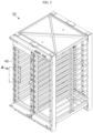
- FIG. 1 is a perspective view of the conventional battery module
- FIG. 2 is a perspective view of the conventional rack case
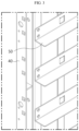
- FIG. 3 is an enlarged view of section A in FIG. 2 .
- the battery module 10 may include a module housing 20 and a plurality of battery cells (not shown) disposed in the module housing 20 and stacked in a direction.
- the rack case 30 may be configured to accommodate a plurality of battery modules 10 shown in FIG. 1 arranged in the top-bottom direction. Inside the rack case 30, the plurality of battery modules 10 may be mounted, spaced apart from each other in the top-bottom direction.
- the rack case 30 may have an accommodation space having an open structure to allow the plurality of battery modules 10 to come and go in the top-bottom direction.
- the rack case 30 may form the accommodation space by a frame 40.
- a support bracket 50 is coupled to the frame 40 and when the plurality of battery modules 10 is mounted in the rack case 30, the battery module 10 is supported by the support bracket 50 of the rack case 30 and mounted for each compartment.
- the battery module 10 received in each compartment needs the module housing 20, and the rack case 30 requires the frame 40 and the support bracket 50.
- the rack case 30 needs a spacing between the upper/lower support brackets 50.
- the conventional battery rack requires many components, so the material cost increases, the assembly process of mounting the battery module 10 to every compartment of the rack case 30 is tedious, the rack case 30 is structurally complex and energy density is reduced as much as the space occupied by other components than the battery cells in each compartment of the rack case 30.
- the present disclosure is designed to address the above-described problem, and therefore the present disclosure is directed to providing a battery pack with reduced material cost, simplified structure and increased energy density.
- the present disclosure is further directed to providing an energy storage system including the battery pack with simplified assembly process and increased energy density.
- a battery pack includes a plurality of posts; a plurality of steel bars connecting the posts facing each other among the plurality of posts and assembled in multiple layers along a height direction of the posts; a plurality of trays situated on the steel bars to form each layer; and a plurality of cell module assemblies situated on the tray of each layer.
- the plurality of cell module assemblies situated on the tray of each layer may be connected to form one battery module, and the battery pack may further include an electrical connection member connecting the battery module of each layer.
- the battery modules are not covered with a module case, and the battery pack may further include a pack case to protect an internal structure.
- the pack case may include a box-shaped container having an open top side.
- the trays may include an upper surface and a sidewall extended downward from the upper surface, and the sidewall may have a recessed groove to fit downward to the steel bars.
- a number of layers of battery modules may be 4 to 6.
- the battery modules are assembled into one pack, and the case is only equipped in each pack, the structure of the battery pack is simplified, energy density increases and the material cost reduces.
- the trays and the steel bars are arranged in multiple layers inside the battery pack, the cell module assemblies of each layer form one battery module and four to six battery modules form the battery pack.
- the battery pack has high density of arrangement of the battery modules, leading to improved space utilization.
- the battery pack including a desired number of layers of battery modules, and free to expand battery capacity.
- the horizontal and vertical areas or footprint dimensions of the battery pack may be standardized, and it may be possible to freely expand in the height direction by increasing the number of layers of battery modules.
- the battery modules may be densely arranged in multiple layers inside the battery pack, so it is easy to design the energy storage system by arranging and stacking battery packs. Compared to the high density design of the conventional battery rack, it may be possible to minimize the assembly process.
- the internal structure of the battery pack may be stably supported by the posts, the trays and the pack case. Accordingly, it may be possible to minimize the movement of the internal structure such as the cell module assemblies in the battery pack, thereby reducing the influence on transportation (vibration).
- the battery pack of the present disclosure is simple and easy to transport and assemble at the installation site, and can achieve an energy storage system at a lower cost in a more straightforward and convenient way than a transportable rack system requiring a means for preventing deformation and damage to the components due to vibration during transportation.
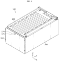
- FIG. 4 is a front perspective view showing a battery pack according to an embodiment of the present disclosure
- FIG. 5 is a perspective view showing a pack case separated from the battery pack of FIG. 4 .
- the battery pack 100 includes the pack case 300 to protect an internal structure 200.
- the battery pack 100 may further include a top cover 400.
- the pack case 300 may include a box-shaped container having an open top side.
- the pack case 300 may cover the front side, rear side, left side, right side and bottom side of the internal structure 200, and the top cover 400 may cover the upper surface of the internal structure 200.
- the pack case 300 may be made of a material having stiffness of a predetermined level or more to protect the internal structure 200.
- the pack case 300 may be made of a metal material having high thermal conductivity for easy heat release.
- the pack case 300 may be made of aluminum or steel.
- the pack case 300 may further include an insulating coating layer on the inner surface.
- the pack case 300 may further include a component for connection with other structure.
- the pack case 300 may have a bracket 310 having a fastening hole at the front side.
- This component may be used to connect a plurality of battery packs 100, and may be used to connect a device or equipment in which the battery pack 100 is to be mounted, for example, a chassis of a vehicle or a frame of an energy storage system.
- the shape of the component may be modified and the component may be omitted.
- the battery pack 100 has a predetermined size in a width direction (X axis direction, left-right direction), a length direction (Y axis direction, front-rear direction) and a height direction (Z axis direction, top-bottom direction), and has an approximately rectangular cuboidal structure in shape.
- the battery pack 100 may have a shape for preventing unnecessary space occupation when densely arranging a plurality of battery packs 100. Additionally, the pack case 300 is easy to manufacture due to its simple structure.
- FIG. 4 shows a cooling medium inlet port 171 and a cooling medium outlet port 174 outside of the pack case 300.
- the cooling medium inlet port 171 and the cooling medium outlet port 174 need to be in communication with the outside to supply a cooling medium from the outside of the battery pack 100 to the inside of the battery pack 100 and discharge the cooling medium to the outside of the battery pack 100, and by this reason, the cooling medium inlet port 171 and the cooling medium outlet port 174 are exposed to the outside of the pack case 300.
- a cooling pipe assembly 170 is connected to the cooling medium inlet port 171 and the cooling medium outlet port 174.
- the cooling related component structure is shown in FIGs. 15 to 17 , and will be described in more detail with reference to FIGs. 15 to 17 .
- the battery pack 100 may further include a battery management system (BMS) 180 and a fuse assembly 210.
- BMS battery management system
- the cooling pipe assembly 170, the BMS 180 and the fuse assembly 210 may be disposed together at the front end of the battery pack 100 without occupying unnecessary areas in the internal space of the battery pack 100 to prevent the decline in energy density of the battery pack 100. Because the cooling pipe assembly 170, the BMS 180 and the fuse assembly 210 are disposed together at the front end of the battery pack 100, the internal space of the pack case 300 may be primarily allocated to cell module assemblies. Accordingly, it may be possible to increase energy density of the battery pack 100.
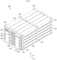
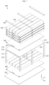
- FIG. 6 is a perspective view showing the assembled state of the main internal structure of the battery pack according to an embodiment of the present disclosure
- FIG. 7 is an exploded perspective view of FIG. 6 .
- a tray 130 is situated on the steel bars 120 of one layer.
- the tray 130 includes a plurality of trays to form each layer.
- the trays 130 are horizontally supported by the steel bars 120.
- the plurality of battery cells that constitutes the cell module assembly 140 may be stacked side by side.
- the battery cells in standing position such that a direction in which electrode leads are drawn faces Y axis direction may be arranged along the X axis direction to form the cell module assembly 140.
- a cell module assembly 140 may include five or more battery cells.
- the plurality of battery cells may be electrically connected either in series or in parallel or both, and electrical connection may be established by connecting the electrode leads of the battery cells by a busbar.
- the cell module assemblies 140 may be arranged in row and column on the tray 130.
- the cell module assemblies 140 having the length direction in Y axis direction are arranged in 5 rows in X axis direction, and the arrangement in a column is repeated in Y axis direction so they are arranged in 5 rows and 2 columns. According to the number of cell module assemblies 140 arranged, the size of the trays 130, the number and placement of posts 110, and the number of steel bars 120 may change to support proper loads.
- the plurality of cell module assemblies 140 situated on the tray 130 of each layer may be connected to form one battery module 150. That is, the cell module assemblies 140 horizontally placed on one layer may be modularized into one unit. Additionally, the battery module 150 of each layer may be connected to each other to form one pack. That is, connection between all the cell module assemblies 140 included in the battery pack 100 may be established by connecting from the battery module 150 of the lowermost layer to the battery module 150 of the uppermost layer. The connection between the cell module assemblies 140 and the connection between the battery modules 150 may be made by a proper electrical connection member such as a cable or a busbar.
- the battery pack 100 of the present disclosure includes the trays 130 supported by the steel bars 120 and arranged in multiple layers in the vertical direction, the plurality of cell module assemblies 140 situated on the tray 130 of each layer is connected to form the battery module 150, and the battery modules 150 are included in multiple layers inside the battery pack 100.
- the number of layers of the battery modules 150 may be 4 to 6, and as shown, the number of layers of the battery modules 150 is 5.
- the battery pack 100 includes the pack case 300 accommodating the battery modules 150 arranged in the top-bottom direction.
- the battery modules 150 are not covered by a module case, and are only covered by the pack case 300 as shown in FIG. 4 .
- the present disclosure includes the battery modules 150 combined into one pack, omits a module case, and finally includes the case covering the entire structure only in the pack, so the structure of the battery pack 100 is simplified, energy density increases and the material cost reduces.
- the trays 130 and the steel bars 120 may be arranged in multiple layers inside the battery pack 100, the cell module assemblies 140 of each layer form one battery module 150, and four to six battery modules 150 may form the battery pack 100.
- the battery pack 100 has high density of arrangement of battery modules 150 without a module case, leading to improved space utilization.
- the battery pack 100 may include a base plate 105 that forms the bottom of the internal structure 200.
- the plurality of posts 110 may be assembled to the base plate 105.
- the base plate 105 may be the base for making the posts 110 stand upright in the vertical direction and stacking the plurality of cell module assemblies 140 of the lowest layer.
- the number and assembly location of posts 110 may change.
- the posts 110 may be included in n rows and m columns along the width direction and the length direction of the battery pack 100, and the steel bars 120 may be assembled between the posts 110 in the same column.
- the posts 110 are included in three columns, and three steel bars 120 in the horizontal plane are necessary.
- a bar-type top frame 165 of a rectangular cross section may be fastened to the top of the posts 110 in parallel to the steel bars 120.
- the top frames 165 may be coupled to the top of the posts 110 on the cell module assemblies 140 of the uppermost layer by bolting, and the stack structure of the cell module assemblies 140 may be coupled with the left surface and the right surface in contact with the posts 110 and the upper surface in contact with the top frames 165. By this configuration, the stack structure of the cell module assemblies 140 may be safely maintained without movement.
- four holes 115 may be arranged at a predetermined interval.
- the total number of layers of the steel bars 120 may be four.
- the steel bars 120 may have a greater length than the distance between the posts 110 facing each other, and two end portions of the steel bars 120 extended through the holes 115 may have an extended surface parallel to the outer surface of the posts 110, or further extended in X axis direction than the outer surface of the posts 110, and thus the steel bars 120 may be supported between the posts 110 reliably and stably.
- the heat sink 160 is situated on the tray 130.
- the plurality of cell module assemblies 140 is placed thereon. Also in this step, the cell module assemblies 140 may be electrically connected.
- One side 144 of the cell module assemblies 140 of the lower layer and one side of the cell module assemblies 140 newly disposed on the tray 130 may be connected to connect the battery module 150 of the lower layer and the battery module 150 of the second layer.
- One side of another cell module assemblies 140 of the second layer may be connected to the cell module assemblies of the upper layer.
- steps S4, S2 and S3 repeat in that order as many times necessary.
- the manufacture of the battery pack 100 may be completed.
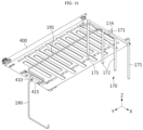
- FIG. 15 is an exploded perspective view of another internal structure that is coupled to FIG. 6
- FIG. 16 is an exploded bottom perspective view of the top cover in FIG. 15
- FIG. 17 is a front enlarged view of FIG. 6
- FIG. 18 is a rear enlarged view of FIG. 6 .
- the cooling pipe assembly 170 may be located at the front end of the battery pack 100 to increase space utilization.
- the cooling pipe assembly 170 may include the cooling medium inlet port 171 for feeding the cooling medium from the outside of the battery pack 100, a cooling medium feed pipe 172 connected to the cooling medium inlet port 171 and the inlet-side connector 173 for connecting the cooling medium feed pipe 172 to the inlet port 163 of each heat sink 160. Additionally, the cooling pipe assembly 170 may include the cooling medium outlet port 174 for discharging the cooling medium to the outside of the battery pack 100, a cooling medium discharge pipe 175 connected to the cooling medium outlet port 174 and the outlet-side connector 176 for connecting the cooling medium discharge pipe 175 to the outlet port 166 of each heat sink 160.
- the cooling medium inlet port 171 and the cooling medium outlet port 174 may be located at the top center of the front end of the battery pack 100 in the length direction. As shown in FIG. 4 , the cooling medium inlet port 171 and the cooling medium outlet port 174 may be exposed to the outside of the pack case 300.
- the cooling medium inlet port 171 and the cooling medium feed pipe 172 are used to feed the cooling medium into the heat sink 160 at the approximately central portion of the battery pack 100.
- the cooling medium feed pipe 172 may be branched into two from one cooling medium inlet port 171, and connected to each heat sink 160.
- the cooling medium of low temperature is preferably concentrated on the central portion of the battery pack 100 to achieve cooling.
- the cooling medium from each heat sink 160 may be fed from the outlet port 166 at two sides of the heat sink 160 to the cooling medium discharge pipe 175 through the outlet-side connector 176, and the cooling medium discharge pipes 175 at two sides may be connected together to one cooling medium outlet port 174, to smoothly discharge the cooling medium to the outside of the battery pack 100.
- the BMS 180 may be further included between the cooling medium feed pipe 172 and the cooling medium discharge pipe 175.
- the BMS 180 may be configured to measure the current and temperature of the battery cells in the battery pack 100, and control the charge/discharge of the battery cells.
- the BMS 180 may be disposed between the cooling medium feed pipe 172 and the cooling medium discharge pipe 175, thereby maximizing space utilization in the battery pack 100.
- the first electrical connection member 190 extended from the cell module assemblies 140 of the lowest layer may be connected to a first terminal portion 410 of the top cover 400, and at the front end of the battery pack 100 in the length direction, the second electrical connection member 195 extended from the cell module assemblies 140 of the uppermost layer may be extended below the top cover 400 and connected to a second terminal portion 415 of the top cover 400.
- the fuse assembly 210 may be, for example, connected to the second electrical connection member 195.
- the fuse assembly 210 is a component including a relay and a resistor, and may play a role in stably supplying or shutting off the battery power to a device or equipment using the battery pack 100 or protecting an electrical grid of the corresponding device or equipment when fault current occurs. According to the present disclosure, the fuse assembly 210 may be efficiently disposed in the available space at the front end of the battery pack 100, thereby achieving space savings.
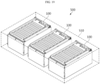
- FIG. 19 is a diagram illustrating an energy storage system according to an embodiment of the present disclosure.
- the energy storage system 500 may include at least one battery pack 100 according to an embodiment of the present disclosure.
- the battery pack 100 may include at least one battery pack or more than one battery pack. Hereinafter, this embodiment will be described based on a plurality of battery packs 100.
- the energy storage system 500 may further include a frame 510.
- the bracket 310 as described with reference to FIG. 4 may be used to connect the battery pack 100 to the frame 510.
- the plurality of battery packs 100 may be electrically connected to each other through a rack busbar (not shown).
- the energy storage system 500 according to the present disclosure may be embodied in various forms, for example, a smart grid system or an electric charging station.
- the battery modules 150 are already densely arranged in multiple layers inside the battery pack 100. Accordingly, it is easy to design the energy storage system 500 by arranging or stacking the battery packs 100. Compared to the high density design of the conventional battery rack, it may be possible to minimize the assembly process.
- the energy storage system 500 may be finished after the battery packs 100 are assembled in the frame 510, then unloaded, transported and installed at the installation site.
- the frame 510 and the battery pack 100 may be transported and assembled at the installation site.
- the internal structure of the battery pack 100 may be stably supported by the post 110, the trays 130 and the pack case 300. Accordingly, the movement of the internal structure such as the cell module assemblies 140 in the battery pack 100 may be minimized, and the influence on transportation (vibration) may be reduced.
- the installation operation may be performed fast in an easy and simple way. Because the battery modules 150 are densely arranged in the battery pack 100, the energy storage system 500 may be efficiently built in a short time. As described above, because the battery pack 100 of the present disclosure is simple and easy to transport and assemble at the installation site, it may be possible to achieve the energy storage system 500 at a low cost in a straightforward and convenient way without needing to convert to a transportable rack system.
Landscapes
- Chemical & Material Sciences (AREA)
- Chemical Kinetics & Catalysis (AREA)
- Electrochemistry (AREA)
- General Chemical & Material Sciences (AREA)
- Engineering & Computer Science (AREA)
- Manufacturing & Machinery (AREA)
- Automation & Control Theory (AREA)
- Aviation & Aerospace Engineering (AREA)
- Battery Mounting, Suspending (AREA)
- Secondary Cells (AREA)
- Connection Of Batteries Or Terminals (AREA)
Abstract
Description
- The present disclosure relates to a battery pack and an energy storage system comprising the same, and more particularly, to a battery pack having high density of arrangement of battery modules for improved space utilization and an energy storage system comprising the same. The present application claims priority to
Korean Patent Application No. 10-2023-0086642 filed on July 4, 2023 - Due to being easily applicable to different types of products and having electrical properties such as high energy density, secondary batteries are commonly applied to not only portable devices but also electric vehicles (EVs) or hybrid electric vehicles (HEVs) that are powered by a source of electric power. Secondary batteries remarkably reduce the use of fossil fuels, and in addition to the primary advantage, they do not generate by-products from the use of energy. From this perspective, secondary batteries are seen as a new source of energy that is more environmentally friendly and energy-efficient.
- The commonly used types of secondary batteries include lithium ion batteries, lithium polymer batteries, nickel cadmium batteries, nickel hydrogen batteries, nickel zinc batteries and so on, and a plurality of battery cells is connected in series or in parallel to form a battery module and a plurality of battery modules forms a battery pack.
- Recently, attention is paid to an Energy Storage System (ESS) that stores the produced electricity in battery cells and supplies to consumers when electricity is needed, thereby maximizing energy use efficiency. The ESS is a system including a few tens to a few hundreds of battery racks, each battery rack including a plurality of battery modules. Additionally, the ESS is used in conjunction with an uninterrupted power supply (UPS) to stably supply the power in case of sudden power outage or failure and a solar power generation system that converts solar energy to electrical energy.
- The battery rack generally includes a metal rack case to protect the plurality of battery modules from external impacts or receive and store them.
FIG. 1 is a perspective view of the conventional battery module,FIG. 2 is a perspective view of the conventional rack case, andFIG. 3 is an enlarged view of section A inFIG. 2 . - Referring to
FIG. 1 , thebattery module 10 may include amodule housing 20 and a plurality of battery cells (not shown) disposed in themodule housing 20 and stacked in a direction. - Referring to
FIGs. 2 and3 , therack case 30 may be configured to accommodate a plurality ofbattery modules 10 shown inFIG. 1 arranged in the top-bottom direction. Inside therack case 30, the plurality ofbattery modules 10 may be mounted, spaced apart from each other in the top-bottom direction. Therack case 30 may have an accommodation space having an open structure to allow the plurality ofbattery modules 10 to come and go in the top-bottom direction. - For example, as shown in
FIGs. 2 and3 in detail, therack case 30 may form the accommodation space by aframe 40. Additionally, asupport bracket 50 is coupled to theframe 40 and when the plurality ofbattery modules 10 is mounted in therack case 30, thebattery module 10 is supported by thesupport bracket 50 of therack case 30 and mounted for each compartment. Thebattery module 10 received in each compartment needs themodule housing 20, and therack case 30 requires theframe 40 and thesupport bracket 50. In addition, therack case 30 needs a spacing between the upper/lower support brackets 50. - As described above, the conventional battery rack requires many components, so the material cost increases, the assembly process of mounting the
battery module 10 to every compartment of therack case 30 is tedious, therack case 30 is structurally complex and energy density is reduced as much as the space occupied by other components than the battery cells in each compartment of therack case 30. - Accordingly, there is a need for a new high-density arrangement structure of the
battery modules 10 to avoid the rise in material cost, simplify the assembly process, improve space utilization and increase energy density. - The present disclosure is designed to address the above-described problem, and therefore the present disclosure is directed to providing a battery pack with reduced material cost, simplified structure and increased energy density.
- The present disclosure is further directed to providing an energy storage system including the battery pack with simplified assembly process and increased energy density.
- The technical problems to be solved by the present disclosure are not limited to the aforementioned problems, and these and other problems will be clearly understood by those skilled in the art from the following description.
- To solve the above-described problem, a battery pack according to an aspect of the present disclosure includes a plurality of posts; a plurality of steel bars connecting the posts facing each other among the plurality of posts and assembled in multiple layers along a height direction of the posts; a plurality of trays situated on the steel bars to form each layer; and a plurality of cell module assemblies situated on the tray of each layer.
- Here, the plurality of cell module assemblies situated on the tray of each layer may be connected to form one battery module, and the battery pack may further include an electrical connection member connecting the battery module of each layer.
- In this instance, the battery modules are not covered with a module case, and the battery pack may further include a pack case to protect an internal structure.
- The pack case may include a box-shaped container having an open top side.
- Preferably, the trays are horizontally supported by the steel bars.
- The battery pack may further include a base plate that forms a bottom, and the plurality of posts may be assembled to the base plate.
- The posts may be assembled to at least four corners of the base plate, and the steel bars may connect the posts facing each other in a width direction of the battery pack and be arranged along a length direction of the battery pack.
- The posts may have holes at a predetermined interval along the height direction of the posts, and the steel bars may be inserted into the holes and assembled between the posts facing each other.
- The trays may include an upper surface and a sidewall extended downward from the upper surface, and the sidewall may have a recessed groove to fit downward to the steel bars.
- The posts may be included in n rows and m columns along a width direction and a length direction of the battery pack, the steel bars may be assembled between the posts in a same column, and a bar-type top frame of a rectangular cross section may be fastened to a top of the posts in parallel to the steel bars.
- The posts may have a rectangular cross section perpendicular to the height direction, and the steel bars may have a circular cross section.
- Preferably, the battery pack further includes a heat sink between the trays and the cell module assemblies for each layer.
- The battery pack may further include a cooling pipe assembly to supply a cooling medium to each heatsink and collect the cooling medium from each heatsink.
- The cooling pipe assembly may be located at a front end of the battery pack in a length direction.
- The cooling pipe assembly may include a cooling medium inlet port for feeding the cooling medium from outside of the battery pack, a cooling medium feed pipe connected to the cooling medium inlet port, an inlet-side connector connecting the cooling medium feed pipe to each heatsink, a cooling medium outlet port for discharging the cooling medium to outside of the battery pack, a cooling medium discharge pipe connected to the cooling medium outlet port and an outlet-side connector connecting the cooling medium discharge pipe to each heatsink.
- The cooling medium inlet port and the cooling medium outlet port may be located at a top center of the front end of the battery pack in the length direction, and the battery pack may further include a Battery Management System (BMS) between the cooling medium feed pipe and the cooling medium discharge pipe.
- The trays and the heatsinks may be extended to the front end of the battery pack in the length direction further than the cell module assemblies, and the inlet-side connector and the outlet-side connector may be located at the extended part of the heatsinks.
- The cell module assemblies may be connected with an electrical connection member.
- The battery pack may further include a top cover covering the cell module assemblies of an uppermost layer on the top frame.
- For example, at a rear end of the battery pack in the length direction, a first electrical connection member extended from the cell module assemblies of a lowest layer may be connected to a first terminal portion of the top cover, and at the front end of the battery pack in the length direction, a second electrical connection member extended from the cell module assemblies of the uppermost layer may be extended below the top cover and connected to a second terminal portion of the top cover.
- A battery pack according to another aspect of the present disclosure includes battery modules in multiple layers, each battery module in which trays supported by steel bars are stacked in multiple layers in a vertical direction, and a plurality of cell module assemblies situated on the trays of each layer is connected to each other.
- Here, a number of layers of battery modules may be 4 to 6.
- In addition, the present disclosure provides an energy storage system including at least one battery pack according to the present disclosure.
- According to the present disclosure, because the battery modules are assembled into one pack, and the case is only equipped in each pack, the structure of the battery pack is simplified, energy density increases and the material cost reduces.
- According to the present disclosure, the trays and the steel bars are arranged in multiple layers inside the battery pack, the cell module assemblies of each layer form one battery module and four to six battery modules form the battery pack. The battery pack has high density of arrangement of the battery modules, leading to improved space utilization.
- According to the present disclosure, it is easy to manufacture the battery pack including a desired number of layers of battery modules, and free to expand battery capacity. The horizontal and vertical areas or footprint dimensions of the battery pack may be standardized, and it may be possible to freely expand in the height direction by increasing the number of layers of battery modules.
- According to the present disclosure, the battery modules may be densely arranged in multiple layers inside the battery pack, so it is easy to design the energy storage system by arranging and stacking battery packs. Compared to the high density design of the conventional battery rack, it may be possible to minimize the assembly process.
- According to the present disclosure, the internal structure of the battery pack may be stably supported by the posts, the trays and the pack case. Accordingly, it may be possible to minimize the movement of the internal structure such as the cell module assemblies in the battery pack, thereby reducing the influence on transportation (vibration). As described above, the battery pack of the present disclosure is simple and easy to transport and assemble at the installation site, and can achieve an energy storage system at a lower cost in a more straightforward and convenient way than a transportable rack system requiring a means for preventing deformation and damage to the components due to vibration during transportation.
- The accompanying drawings illustrate exemplary embodiments of the present disclosure and together with the following detailed description, serve to provide a better understanding of the technical aspect of the present disclosure, and the present disclosure should not be construed as being limited to the drawings.
-
FIG. 1 is a perspective view of a conventional battery pack. -
FIG. 2 is a perspective view of a conventional rack case. -
FIG. 3 is an enlarged view of section A inFIG. 2 . -
FIG. 4 is a front perspective view showing a battery pack according to an embodiment of the present disclosure. -
FIG. 5 is a perspective view showing a pack case separated from the battery pack ofFIG. 4 . -
FIG. 6 is a perspective view showing an assembled state of a main internal structure of a battery pack according to an embodiment of the present disclosure. -
FIG. 7 is an exploded perspective view ofFIG. 6 . -
FIGs. 8 to 14 are diagrams illustrating a method for manufacturing a battery pack according to an embodiment of the present disclosure. -
FIG. 15 is an exploded perspective view of another internal structure that is coupled toFIG. 6 . -
FIG. 16 is an exploded bottom perspective view of a top cover inFIG. 15 . -
FIG. 17 is a front enlarged view ofFIG. 6 . -
FIG. 18 is a rear enlarged view ofFIG. 6 . -
FIG. 19 is a diagram illustrating an energy storage system according to an embodiment of the present disclosure. - Hereinafter, the exemplary embodiments of the present disclosure will be described in detail with reference to the accompanying drawings. Prior to the description, it should be understood that the terms or words used in the specification and the appended claims should not be construed as limited to general and dictionary meanings, but rather interpreted based on the meanings and concepts corresponding to the technical aspect of the present disclosure on the basis of the principle that the inventor is allowed to define the terms appropriately for the best explanation. Therefore, the embodiments described herein and illustrations in the accompanying drawings are provided by way of illustration but not intended to be limiting, and thus it should be understood that a variety of other equivalents and modifications could have been made at the time the application was filed.
-
FIG. 4 is a front perspective view showing a battery pack according to an embodiment of the present disclosure, andFIG. 5 is a perspective view showing a pack case separated from the battery pack ofFIG. 4 . - Referring to
FIGs. 4 and5 , thebattery pack 100 according to an embodiment of the present disclosure includes thepack case 300 to protect aninternal structure 200. Thebattery pack 100 may further include atop cover 400. - The
pack case 300 may include a box-shaped container having an open top side. Thepack case 300 may cover the front side, rear side, left side, right side and bottom side of theinternal structure 200, and thetop cover 400 may cover the upper surface of theinternal structure 200. - The
pack case 300 may be made of a material having stiffness of a predetermined level or more to protect theinternal structure 200. Preferably, thepack case 300 may be made of a metal material having high thermal conductivity for easy heat release. For example, thepack case 300 may be made of aluminum or steel. Additionally, to achieve electrical insulation, thepack case 300 may further include an insulating coating layer on the inner surface. - The
pack case 300 may further include a component for connection with other structure. For example, as shown, thepack case 300 may have abracket 310 having a fastening hole at the front side. This component may be used to connect a plurality of battery packs 100, and may be used to connect a device or equipment in which thebattery pack 100 is to be mounted, for example, a chassis of a vehicle or a frame of an energy storage system. The shape of the component may be modified and the component may be omitted. - The
battery pack 100 has a predetermined size in a width direction (X axis direction, left-right direction), a length direction (Y axis direction, front-rear direction) and a height direction (Z axis direction, top-bottom direction), and has an approximately rectangular cuboidal structure in shape. Thebattery pack 100 may have a shape for preventing unnecessary space occupation when densely arranging a plurality of battery packs 100. Additionally, thepack case 300 is easy to manufacture due to its simple structure. - Meanwhile,
FIG. 4 shows a coolingmedium inlet port 171 and a coolingmedium outlet port 174 outside of thepack case 300. The coolingmedium inlet port 171 and the coolingmedium outlet port 174 need to be in communication with the outside to supply a cooling medium from the outside of thebattery pack 100 to the inside of thebattery pack 100 and discharge the cooling medium to the outside of thebattery pack 100, and by this reason, the coolingmedium inlet port 171 and the coolingmedium outlet port 174 are exposed to the outside of thepack case 300. A coolingpipe assembly 170 is connected to the coolingmedium inlet port 171 and the coolingmedium outlet port 174. The cooling related component structure is shown inFIGs. 15 to 17 , and will be described in more detail with reference toFIGs. 15 to 17 . - Additionally, as shown in
FIG. 5 , thebattery pack 100 may further include a battery management system (BMS) 180 and afuse assembly 210. The coolingpipe assembly 170, theBMS 180 and thefuse assembly 210 may be disposed together at the front end of thebattery pack 100 without occupying unnecessary areas in the internal space of thebattery pack 100 to prevent the decline in energy density of thebattery pack 100. Because the coolingpipe assembly 170, theBMS 180 and thefuse assembly 210 are disposed together at the front end of thebattery pack 100, the internal space of thepack case 300 may be primarily allocated to cell module assemblies. Accordingly, it may be possible to increase energy density of thebattery pack 100. -
FIG. 6 is a perspective view showing the assembled state of the main internal structure of the battery pack according to an embodiment of the present disclosure, andFIG. 7 is an exploded perspective view ofFIG. 6 . - Describing the
internal structure 200 of thebattery pack 100 with reference toFIGs. 6 and7 , thebattery pack 100 includes a plurality ofposts 110 and a plurality of steel bars 120. The steel bars 120 are connected between theposts 110 facing each other among the plurality ofposts 110. Additionally, the steel bars 120 are assembled in multiple layers along the height direction of theposts 110. - A
tray 130 is situated on the steel bars 120 of one layer. Thetray 130 includes a plurality of trays to form each layer. Preferably, thetrays 130 are horizontally supported by the steel bars 120. - A plurality of
cell module assemblies 140 is situated on thetray 130 of each layer. Theposts 110 and the steel bars 120 may play a main framework role for situating thecell module assemblies 140. Theposts 110, the steel bars 120 and thetrays 130 may be designed not to occupy the larger volume than thecell module assemblies 140 in order to increase energy density of thebattery pack 100. - The
cell module assembly 140 is an assembly of battery cells. The plurality of battery cells may be arranged in a direction within thecell module assembly 140. The battery cells that constitute thecell module assembly 140 may include, for example, pouch-type battery cells. The pouch-type battery cells have a suitable shape for maximizing energy density when stacking them. However, the battery cells applied to the present disclosure are not limited to a particular shape, and may include battery cells of any shape, for example, prismatic cells or cylindrical cells so long as they correspond to rechargeable secondary batteries. - Additionally, the plurality of battery cells that constitutes the
cell module assembly 140 may be stacked side by side. When pouch-type battery cells are applied, the battery cells in standing position such that a direction in which electrode leads are drawn faces Y axis direction may be arranged along the X axis direction to form thecell module assembly 140. For example, acell module assembly 140 may include five or more battery cells. The plurality of battery cells may be electrically connected either in series or in parallel or both, and electrical connection may be established by connecting the electrode leads of the battery cells by a busbar. - The
cell module assemblies 140 may be arranged in row and column on thetray 130. In the illustrated example, thecell module assemblies 140 having the length direction in Y axis direction are arranged in 5 rows in X axis direction, and the arrangement in a column is repeated in Y axis direction so they are arranged in 5 rows and 2 columns. According to the number ofcell module assemblies 140 arranged, the size of thetrays 130, the number and placement ofposts 110, and the number ofsteel bars 120 may change to support proper loads. - Here, the plurality of
cell module assemblies 140 situated on thetray 130 of each layer may be connected to form onebattery module 150. That is, thecell module assemblies 140 horizontally placed on one layer may be modularized into one unit. Additionally, thebattery module 150 of each layer may be connected to each other to form one pack. That is, connection between all thecell module assemblies 140 included in thebattery pack 100 may be established by connecting from thebattery module 150 of the lowermost layer to thebattery module 150 of the uppermost layer. The connection between thecell module assemblies 140 and the connection between thebattery modules 150 may be made by a proper electrical connection member such as a cable or a busbar. - The
battery pack 100 of the present disclosure includes thetrays 130 supported by the steel bars 120 and arranged in multiple layers in the vertical direction, the plurality ofcell module assemblies 140 situated on thetray 130 of each layer is connected to form thebattery module 150, and thebattery modules 150 are included in multiple layers inside thebattery pack 100. Here, for example, the number of layers of thebattery modules 150 may be 4 to 6, and as shown, the number of layers of thebattery modules 150 is 5. - As described above, the
battery pack 100 includes thepack case 300 accommodating thebattery modules 150 arranged in the top-bottom direction. In this instance, as opposed to the conventional art, thebattery modules 150 are not covered by a module case, and are only covered by thepack case 300 as shown inFIG. 4 . As described above, the present disclosure includes thebattery modules 150 combined into one pack, omits a module case, and finally includes the case covering the entire structure only in the pack, so the structure of thebattery pack 100 is simplified, energy density increases and the material cost reduces. - According to the present disclosure, the
trays 130 and the steel bars 120 may be arranged in multiple layers inside thebattery pack 100, thecell module assemblies 140 of each layer form onebattery module 150, and four to sixbattery modules 150 may form thebattery pack 100. Thebattery pack 100 has high density of arrangement ofbattery modules 150 without a module case, leading to improved space utilization. - Describing the
internal structure 200 of thebattery pack 100 in more detail with reference toFIGs. 6 and7 , thebattery pack 100 may include abase plate 105 that forms the bottom of theinternal structure 200. The plurality ofposts 110 may be assembled to thebase plate 105. Thebase plate 105 may be the base for making theposts 110 stand upright in the vertical direction and stacking the plurality ofcell module assemblies 140 of the lowest layer. - The
posts 110 are assembled to at least four corners of thebase plate 105. The steel bars 120 may connect theposts 110 facing each other in the width direction of thebattery pack 100 and may be arranged along the length direction of thebattery pack 100. - Depending on the size of the
base plate 105 or the placement and number ofcell module assemblies 140 that will be mounted on thebase plate 105, the number and assembly location ofposts 110 may change. For example, theposts 110 may be included in n rows and m columns along the width direction and the length direction of thebattery pack 100, and the steel bars 120 may be assembled between theposts 110 in the same column. In the illustrated example, theposts 110 are included in three columns, and threesteel bars 120 in the horizontal plane are necessary. - A bar-
type top frame 165 of a rectangular cross section may be fastened to the top of theposts 110 in parallel to the steel bars 120. The top frames 165 may be coupled to the top of theposts 110 on thecell module assemblies 140 of the uppermost layer by bolting, and the stack structure of thecell module assemblies 140 may be coupled with the left surface and the right surface in contact with theposts 110 and the upper surface in contact with the top frames 165. By this configuration, the stack structure of thecell module assemblies 140 may be safely maintained without movement. - The
posts 110 may haveholes 115 arranged at a predetermined interval along the height direction of theposts 110, and the steel bars 120 may be inserted into theholes 115 and assembled between theposts 110 facing each other. - In the illustrated example, four
holes 115 may be arranged at a predetermined interval. When inserting thesteel bar 120 into eachhole 115, the total number of layers of the steel bars 120 may be four. - The steel bars 120 may have a greater length than the distance between the
posts 110 facing each other, and two end portions of the steel bars 120 extended through theholes 115 may have an extended surface parallel to the outer surface of theposts 110, or further extended in X axis direction than the outer surface of theposts 110, and thus the steel bars 120 may be supported between theposts 110 reliably and stably. - The
tray 130 may include anupper surface 132 and asidewall 134 extended downward from theupper surface 132, and thesidewall 134 may have a recessedgroove 136 into which the steel bars 120 are inserted downwards. Because of including theupper surface 132 and thesidewall 134, the weight may be reduced compared to a hexagonal plate as a whole, and forming the recessedgroove 136 in thethin sidewall 134 rather than forming a long groove of a shape that will be fastened to the steel bars 120 may have a beneficial effect on production and material cost savings. - The
posts 110 may have a rectangular cross section perpendicular to the height direction. Theposts 110 may not occupy the large area in the internal space of thepack case 300, and may have a larger area of contact with thecell module assemblies 140. - The steel bars 120 may have a circular cross section. The
holes 115 and the recessedgrooves 136 may conform to the shape of the steel bars 120. When the steel bars 120 have a circular cross section, there is no need for a special alignment process when inserting the steel bars 120 into theholes 115, and it may be easy to fasten by allowing the steel bars 120 to pass through theholes 115 facing each other, thereby improving assembly efficiency. Additionally, because a portion of the steel bars 120 supporting thetrays 130 is circular in shape, when the heavycell module assemblies 140 are placed on thetrays 130, loads are not concentrated on narrow areas, thereby maintaining structural strength. - The plurality of
trays 130 form each layer. In the illustrated example, the number of layers of thetrays 130 is 4. Thebase plate 105 at the bottom also form one layer. Accordingly, in this embodiment, the number of layers in which thecell module assemblies 140 may be situated is 5. - The plurality of
cell module assemblies 140 is situated in each layer. Thecell module assemblies 140 may be included in o rows and p columns in one layer along the width direction and the length direction of thebattery pack 100. In the illustrated example, thecell module assemblies 140 are arranged in 5 rows and 2 columns, totaling 10 in one layer, and the total number of layers is 5, so the total number of thecell module assemblies 140 in thebattery pack 100 amounts to 50. As thecell module assemblies 140 of each layer form onebattery module 150, in the illustrated example, the number of layers of thebattery modules 150 is 5. - According to the present disclosure, it is easy to manufacture the
battery pack 100 including a desired number of layers of thebattery modules 150, and free to expand battery capacity. The horizontal and vertical areas or footprint dimensions of thebattery pack 100 may be standardized. The size of thebattery pack 100 in the height direction and capacity may be freely expanded by increasing the number of layers of thebattery modules 150. - The
posts 110 may regulate the front-rear and left-right movement of onebattery module 150 including thecell module assemblies 140 of one layer connected to each other. Thetrays 130 supported by the steel bars 120 may regulate the upward and downward movement of thebattery modules 150. Accordingly, in the event of movement of thebattery pack 100, the movement of thebattery modules 150 in thepack case 300 may be prevented by theposts 110 and thetrays 130. Because thebattery modules 150 are very heavy, even a small movement has great influence on the surrounding component. According to the present disclosure, it may be possible to prevent the movement of thebattery modules 150, thereby improving performance of thebattery pack 100 and ensuring safe and long-term use of thebattery pack 100. - Preferably, the
battery pack 100 further includes aheat sink 160 between thetray 130 and thecell module assemblies 140 for each layer. Here, theheat sink 160 refers to an object that absorbs heat from another object and emits heat through direct/indirect thermal contact. Theheat sink 160 may be provided for eachbattery module 150. The heat sinks 160 may be configured to cool thebattery modules 150 by thermal contact with thebattery modules 150. To this end, theheat sinks 160 may be made of metal having high heat conductivity and heat resistance. For example, theheat sinks 160 may be made of an aluminum alloy having light weight and high thermal conductivity. - The heat sinks 160 may release heat to ambient air (air) or the cooling medium passing through the heat sinks 160. For example, the cooling medium may be water or oil. This embodiment further includes the cooling
pipe assembly 170 connected to theheat sinks 160 to make use of the cooling medium. To allow the cooling medium to circulate, for connection to the coolingpipe assembly 170, theheat sinks 160 may have aninlet port 163 and anoutlet port 166, and theheat sinks 160 may have flow channels inside. As described in more detail below with reference toFIG. 15 , etc., the coolingpipe assembly 170 may include an inlet-side connector 173 for connection to theinlet port 163 and an outlet-side connector 176 for connection to theoutlet port 166 as shown inFIG. 6 . - In the
battery pack 100, thebattery modules 150 may be mounted, spaced apart from each other in the top-bottom direction by the thickness of thetrays 130 and the heat sinks 160. Thetrays 130 and theheat sinks 160 may be designed with minimal thickness. Through this, the plurality ofbattery modules 150 may be mounted with high density of arrangement without unnecessary space occupation in the top-bottom direction inside thebattery pack 100. - Here, the
posts 110 and thetrays 130 may be included in the movement paths of heat during dissipation of heat generated from thebattery modules 150, and be made of a material having high thermal conductivity to improve heat transfer efficiency. -
FIGs. 8 to 14 are diagrams illustrating a method for manufacturing the battery pack according to an embodiment of the present disclosure. Not only the method for manufacturing thebattery pack 100 but also the detailed configuration of thebattery pack 100 will be understood more clearly from the following description with reference toFIGs. 8 to 14 . - Referring to
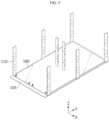
FIG. 8 , theposts 110 are assembled to the base plate 105 (step S1). The assembly between thebase plate 105 and theposts 110 may be done by a variety of methods, for example, interference fitting, bolting, adhesion or welding. - As mentioned above, the
posts 110 have a rectangular cross section, and are preferably disposed with the long axis in cross section facing thebattery cell assemblies 140 to increase the area of contact with thebattery cell assemblies 140. Additionally, this embodiment takes an example of thebattery cell assembly 140 including theposts 110 arranged in rows and columns, for example, three columns. The number ofposts 110 in the middle column may be larger than the number ofposts 110 in another column to provide a stronger support. - Subsequently, as shown in
FIG. 9 , thefirst heat sink 160 is situated on the base plate 105 (step S2). Theheat sink 160 may be assembled after it has been moved downward from the top of theposts 110, and in the illustrated example, theheat sink 160 is formed with a structure that allows themiddle posts 110 to pass through. Theheat sink 160 may be disposed at two locations in one layer, avoiding the middle posts 110. - Subsequently, referring to
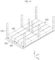
FIG. 10 , the plurality ofcell module assemblies 140 is placed on the heat sink 160 (step S3). In this step, thecell module assemblies 140 may be electrically connected to form thebattery module 150. -
FIG. 11 is a top view of the assembled state ofFIG. 10 to schematically show the electrical connection relationship. Thecell module assemblies 140 placed on one layer may be connected by a proper electrical connection means. The direction of current flow between thecell module assemblies 140 may be, for example, as indicated by the arrow. Oneside 144 of acell module assembly 140 may be connected to the cell module assembly of the upper layer, and oneside 146 of anothercell module assembly 140 may be connected to a terminal portion for connection to an external terminal. - Subsequently, referring to
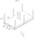
FIG. 12 , the steel bars 120 are assembled to theposts 110, and thetray 130 is situated thereon to support it (step S4). -
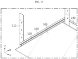
FIGs. 13 and14 are enlarged views showing the assembly relationship between the steel bar and the tray. - As mentioned above, the
tray 130 includes theupper surface 132, thesidewall 134 and the recessedgroove 136. Thetray 130 may be moved from top to bottom of the steel bars 120 and assembled so that the steel bars 120 are inserted into the recessedgroove 136. - Subsequently, in the same way as the S2 described with reference to
FIG. 9 , theheat sink 160 is situated on thetray 130. Subsequently, in the same way as the step S3 described with reference toFIG. 10 , the plurality ofcell module assemblies 140 is placed thereon. Also in this step, thecell module assemblies 140 may be electrically connected. Oneside 144 of thecell module assemblies 140 of the lower layer and one side of thecell module assemblies 140 newly disposed on thetray 130 may be connected to connect thebattery module 150 of the lower layer and thebattery module 150 of the second layer. One side of anothercell module assemblies 140 of the second layer may be connected to the cell module assemblies of the upper layer. - Subsequently, the steps S4, S2 and S3 repeat in that order as many times necessary.
- Subsequently, when the assembly of other structure such as cooling related component or the
BMS 180 is completed, and thepack case 300 is assembled, the manufacture of thebattery pack 100 may be completed. -
FIG. 15 is an exploded perspective view of another internal structure that is coupled toFIG. 6 , andFIG. 16 is an exploded bottom perspective view of the top cover inFIG. 15 .FIG. 17 is a front enlarged view ofFIG. 6 , andFIG. 18 is a rear enlarged view ofFIG. 6 . - Referring to
FIGs. 15 to 18 , thebattery pack 100 may further include the coolingpipe assembly 170 to supply the cooling medium to eachheat sink 160 and collect the cooling medium from eachheat sink 160. - As mentioned above, the cooling
pipe assembly 170 may be located at the front end of thebattery pack 100 to increase space utilization. - The cooling
pipe assembly 170 may include the coolingmedium inlet port 171 for feeding the cooling medium from the outside of thebattery pack 100, a coolingmedium feed pipe 172 connected to the coolingmedium inlet port 171 and the inlet-side connector 173 for connecting the coolingmedium feed pipe 172 to theinlet port 163 of eachheat sink 160. Additionally, the coolingpipe assembly 170 may include the coolingmedium outlet port 174 for discharging the cooling medium to the outside of thebattery pack 100, a coolingmedium discharge pipe 175 connected to the coolingmedium outlet port 174 and the outlet-side connector 176 for connecting the coolingmedium discharge pipe 175 to theoutlet port 166 of eachheat sink 160. - The cooling
medium inlet port 171 and the coolingmedium outlet port 174 may be located at the top center of the front end of thebattery pack 100 in the length direction. As shown inFIG. 4 , the coolingmedium inlet port 171 and the coolingmedium outlet port 174 may be exposed to the outside of thepack case 300. The coolingmedium inlet port 171 and the coolingmedium feed pipe 172 are used to feed the cooling medium into theheat sink 160 at the approximately central portion of thebattery pack 100. The coolingmedium feed pipe 172 may be branched into two from one coolingmedium inlet port 171, and connected to eachheat sink 160. Usually, heat accumulate at the central portion of thebattery pack 100 which in turn, is likely to be heated to high temperature, so the cooling medium of low temperature is preferably concentrated on the central portion of thebattery pack 100 to achieve cooling. The cooling medium from eachheat sink 160 may be fed from theoutlet port 166 at two sides of theheat sink 160 to the coolingmedium discharge pipe 175 through the outlet-side connector 176, and the coolingmedium discharge pipes 175 at two sides may be connected together to one coolingmedium outlet port 174, to smoothly discharge the cooling medium to the outside of thebattery pack 100. - Inside of the
pack case 300, theBMS 180 may be further included between the coolingmedium feed pipe 172 and the coolingmedium discharge pipe 175. TheBMS 180 may be configured to measure the current and temperature of the battery cells in thebattery pack 100, and control the charge/discharge of the battery cells. TheBMS 180 may be disposed between the coolingmedium feed pipe 172 and the coolingmedium discharge pipe 175, thereby maximizing space utilization in thebattery pack 100. - The
trays 130 and theheat sinks 160 may be extended to the front end of thebattery pack 100 further than thecell module assemblies 140, and theinlet port 163 and theoutlet port 166 may be located at the extended part of the heat sinks 160. The coolingpipe assembly 170 may be assembled to theinlet port 163 and theoutlet port 166 at this location, thereby forming a compact structure without occupying a large space inside thebattery pack 100. Additionally, theBMS 180 may be disposed in the empty space between the coolingmedium feed pipe 172 and the coolingmedium discharge pipe 175, thereby improving energy density of thebattery pack 100. Other electrical component such as thefuse assembly 210 may be disposed at the front end of thebattery pack 100 adjacent to theBMS 180. - Additionally, the
cell module assemblies 140 may be connected withelectrical connection members electrical connection members - For example, at the rear end of the
battery pack 100, the firstelectrical connection member 190 extended from thecell module assemblies 140 of the lowest layer may be connected to a firstterminal portion 410 of thetop cover 400, and at the front end of thebattery pack 100 in the length direction, the secondelectrical connection member 195 extended from thecell module assemblies 140 of the uppermost layer may be extended below thetop cover 400 and connected to a secondterminal portion 415 of thetop cover 400. - Additionally, the
fuse assembly 210 may be, for example, connected to the secondelectrical connection member 195. Thefuse assembly 210 is a component including a relay and a resistor, and may play a role in stably supplying or shutting off the battery power to a device or equipment using thebattery pack 100 or protecting an electrical grid of the corresponding device or equipment when fault current occurs. According to the present disclosure, thefuse assembly 210 may be efficiently disposed in the available space at the front end of thebattery pack 100, thereby achieving space savings. -
FIG. 19 is a diagram illustrating an energy storage system according to an embodiment of the present disclosure. - Referring to
FIG. 19 , theenergy storage system 500 may include at least onebattery pack 100 according to an embodiment of the present disclosure. - The
battery pack 100 may include at least one battery pack or more than one battery pack. Hereinafter, this embodiment will be described based on a plurality of battery packs 100. - When the
energy storage system 500 includes the plurality of battery packs 100, theenergy storage system 500 may further include aframe 510. Thebracket 310 as described with reference toFIG. 4 may be used to connect thebattery pack 100 to theframe 510. - The
frame 510 may be configured to accommodate the plurality of battery packs 100, and have an accommodation space for accommodating the plurality of battery packs 100. - The plurality of battery packs 100 may be electrically connected to each other through a rack busbar (not shown). The
energy storage system 500 according to the present disclosure may be embodied in various forms, for example, a smart grid system or an electric charging station. - According to the present disclosure, the
battery modules 150 are already densely arranged in multiple layers inside thebattery pack 100. Accordingly, it is easy to design theenergy storage system 500 by arranging or stacking the battery packs 100. Compared to the high density design of the conventional battery rack, it may be possible to minimize the assembly process. - The
energy storage system 500 according to the present disclosure may be finished after the battery packs 100 are assembled in theframe 510, then unloaded, transported and installed at the installation site. Theframe 510 and thebattery pack 100 may be transported and assembled at the installation site. - The trends of ESS move towards minimizing the on-the-spot task. Accordingly, it is necessary to mount the battery packs in the rack case before unloading. However, a transportable rack system is required to prevent deformation and damage to components due to vibration during transportation.
- According to the present disclosure, the internal structure of the
battery pack 100 may be stably supported by thepost 110, thetrays 130 and thepack case 300. Accordingly, the movement of the internal structure such as thecell module assemblies 140 in thebattery pack 100 may be minimized, and the influence on transportation (vibration) may be reduced. When installing theenergy storage system 500 at the installation site after the transportation of thebattery pack 100, the installation operation may be performed fast in an easy and simple way. Because thebattery modules 150 are densely arranged in thebattery pack 100, theenergy storage system 500 may be efficiently built in a short time. As described above, because thebattery pack 100 of the present disclosure is simple and easy to transport and assemble at the installation site, it may be possible to achieve theenergy storage system 500 at a low cost in a straightforward and convenient way without needing to convert to a transportable rack system. - The terms indicating directions such as upper, lower, left, right, front and rear are used for convenience of description, but it is obvious to those skilled in the art that the terms may change depending on the position of the stated element or an observer.
- Although the present disclosure has been hereinabove described with regard to a limited number of embodiments and drawings, the present disclosure is not limited thereto and it is apparent that a variety of changes and modifications may be made by those skilled in the art within the technical aspect of the present disclosure and the scope of the appended claims and their equivalents.
[List of Reference Numerals] 100: Battery pack 105: Base plate 110: Post 115: Hole 120: Steel bar 130: Tray 136: Recessed groove 140: Cell module assembly 150: Battery module 160: Heat sink 165: Top frame 170: Cooling pipe assembly 171: Cooling medium inlet port 172: Cooling medium feed pipe 173: Inlet-side connector 174: Cooling medium outlet port 175: Cooling medium discharge pipe 176: Outlet-side connector 180: BMS 190, 195: Electrical connection member 200: Internal structure 300: Pack case 310: Bracket 400: Top cover 410: First terminal portion 415: Second terminal portion 500: Energy storage system 510: Frame
Claims (24)
- A battery pack comprising:a plurality of posts;a plurality of steel bars connecting the posts facing each other among the plurality of posts and assembled in multiple layers along a height direction of the posts;a plurality of trays situated on the steel bars to form each layer; anda plurality of cell module assemblies situated on the tray of each layer.
- The battery pack according to claim 1, wherein the plurality of cell module assemblies situated on the tray of each layer is connected to form one battery module, and the battery pack further comprises an electrical connection member connecting the battery module of each layer.
- The battery pack according to claim 2, wherein the battery modules are not covered with a module case, and the battery pack further comprises a pack case to protect an internal structure.
- The battery pack according to claim 3, wherein the pack case includes a box-shaped container having an open top side.
- The battery pack according to claim 1, wherein the trays are horizontally supported by the steel bars.
- The battery pack according to claim 1, wherein the battery pack further comprises a base plate that forms a bottom, and
wherein the plurality of posts is assembled to the base plate. - The battery pack according to claim 6, wherein the posts are assembled to at least four corners of the base plate, and the steel bars connect the posts facing each other in a width direction of the battery pack and are arranged along a length direction of the battery pack.
- The battery pack according to claim 7, wherein the posts have holes at a predetermined interval along the height direction of the posts, and the steel bars are inserted into the holes and assembled between the posts facing each other.
- The battery pack according to claim 1, wherein the trays include an upper surface and a sidewall extended downward from the upper surface, and the sidewall has a recessed groove to fit downward to the steel bars.
- The battery pack according to claim 1, wherein the posts are included in n rows and m columns along a width direction and a length direction of the battery pack, the steel bars are assembled between the posts in a same column, and a bar-type top frame of a rectangular cross section is fastened to a top of the posts in parallel to the steel bars.
- The battery pack according to claim 1, wherein the posts have a rectangular cross section perpendicular to the height direction, and the steel bars have a circular cross section.
- The battery pack according to claim 1, further comprising:
a heat sink between the trays and the cell module assemblies for each layer. - The battery pack according to claim 12, wherein the battery pack further comprises a cooling pipe assembly to supply a cooling medium to each heatsink and collect the cooling medium from each heatsink.
- The battery pack according to claim 13, wherein the cooling pipe assembly is located at a front end of the battery pack in a length direction.
- The battery pack according to claim 14, wherein the cooling pipe assembly includes a cooling medium inlet port for feeding the cooling medium from outside of the battery pack, a cooling medium feed pipe connected to the cooling medium inlet port, an inlet-side connector connecting the cooling medium feed pipe to each heatsink, a cooling medium outlet port for discharging the cooling medium to outside of the battery pack, a cooling medium discharge pipe connected to the cooling medium outlet port and an outlet-side connector connecting the cooling medium discharge pipe to each heatsink.
- The battery pack according to claim 15, wherein the cooling medium inlet port and the cooling medium outlet port is located at a top center of the front end of the battery pack in the length direction, and the battery pack further comprises a Battery Management System (BMS) between the cooling medium feed pipe and the cooling medium discharge pipe.
- The battery pack according to claim 16, wherein the trays and the heatsinks are extended to the front end of the battery pack in the length direction further than the cell module assemblies, and the inlet-side connector and the outlet-side connector are located at the extended part of the heatsinks.
- The battery pack according to claim 1, wherein the cell module assemblies are connected with an electrical connection member.
- The battery pack according to claim 10, wherein the battery pack further comprises a top cover covering the cell module assemblies of an uppermost layer on the top frame.
- The battery pack according to claim 19, wherein at a rear end of the battery pack in the length direction, a first electrical connection member extended from the cell module assemblies of a lowest layer is connected to a first terminal portion of the top cover, and at the front end of the battery pack in the length direction, a second electrical connection member extended from the cell module assemblies of the uppermost layer is extended below the top cover and connected to a second terminal portion of the top cover.
- A battery pack comprising:
battery modules in multiple layers, each battery module in which trays supported by steel bars are stacked in multiple layers in a vertical direction, and a plurality of cell module assemblies situated on the trays of each layer is connected to each other. - The battery pack according to claim 21, wherein the battery modules are not covered with a module case, and the battery pack further comprises a pack case to protect an internal structure.
- The battery pack according to claim 21, wherein a number of layers of battery modules is 4 to 6.
- An energy storage system comprising at least one battery pack according to any one of claims 1 to 23.
Applications Claiming Priority (2)
| Application Number | Priority Date | Filing Date | Title |
|---|---|---|---|
| KR1020230086642A KR20250006615A (en) | 2023-07-04 | 2023-07-04 | Battery pack and energy storage system comprising the same |
| PCT/KR2024/008168 WO2025009770A1 (en) | 2023-07-04 | 2024-06-13 | Battery pack and energy storage system comprising same |
Publications (2)
| Publication Number | Publication Date |
|---|---|
| EP4579908A1 true EP4579908A1 (en) | 2025-07-02 |
| EP4579908A4 EP4579908A4 (en) | 2025-09-10 |
Family
ID=94172002
Family Applications (1)
| Application Number | Title | Priority Date | Filing Date |
|---|---|---|---|
| EP24836219.6A Pending EP4579908A4 (en) | 2023-07-04 | 2024-06-13 | BATTERY PACK AND ENERGY STORAGE SYSTEM |
Country Status (6)
| Country | Link |
|---|---|
| EP (1) | EP4579908A4 (en) |
| JP (1) | JP2026502378A (en) |
| KR (1) | KR20250006615A (en) |
| CN (1) | CN119908048A (en) |
| AU (1) | AU2024290604A1 (en) |
| WO (1) | WO2025009770A1 (en) |
Family Cites Families (12)
| Publication number | Priority date | Publication date | Assignee | Title |
|---|---|---|---|---|
| US5981101A (en) * | 1997-06-02 | 1999-11-09 | Gnb Technologies, Inc. | Modular cell tray assembly for sealed lead-acid cells |
| US20140134460A1 (en) * | 2012-11-13 | 2014-05-15 | Samsung Sdi Co., Ltd. | Energy storage system |
| JP6636898B2 (en) * | 2016-11-11 | 2020-01-29 | 東芝三菱電機産業システム株式会社 | Power storage device |
| KR101799537B1 (en) * | 2017-01-23 | 2017-11-20 | (주)알씨디에이치 | Assistant DC Power Supplying System for Nuclear Power Plant |
| CN208111534U (en) * | 2018-04-24 | 2018-11-16 | 合肥国轩高科动力能源有限公司 | A fixing structure for a power battery module |
| CN209104238U (en) * | 2018-12-29 | 2019-07-12 | 宁德时代新能源科技股份有限公司 | battery pack |
| NO20200576A1 (en) * | 2019-05-24 | 2020-11-25 | Man Energy Solutions Se | Energy storage unit mounting facility and arrangement of the same and multiple energy storage unit |
| KR102757234B1 (en) * | 2019-10-14 | 2025-01-17 | 주식회사 엘지에너지솔루션 | Battery pack and manufacturing method thereof |
| JP7434966B2 (en) * | 2020-02-05 | 2024-02-21 | 株式会社豊田自動織機 | battery pack |
| KR20200106465A (en) | 2020-08-12 | 2020-09-14 | 정진욱 | The made method of multidirectional clean aspiration filter, thereof its putting on the air cool cleaners, insect nets or sanitary napkins, |
| CN216793808U (en) * | 2021-12-28 | 2022-06-21 | 厦门海辰新能源科技有限公司 | Energy storage device |
| CN114914613A (en) * | 2022-03-09 | 2022-08-16 | 和信精密科技(吴江)有限公司 | Assembled battery rack |
-
2023
- 2023-07-04 KR KR1020230086642A patent/KR20250006615A/en active Pending
-
2024
- 2024-06-13 EP EP24836219.6A patent/EP4579908A4/en active Pending
- 2024-06-13 CN CN202480004100.3A patent/CN119908048A/en active Pending
- 2024-06-13 JP JP2025538020A patent/JP2026502378A/en active Pending
- 2024-06-13 WO PCT/KR2024/008168 patent/WO2025009770A1/en not_active Ceased
- 2024-06-13 AU AU2024290604A patent/AU2024290604A1/en active Pending
Also Published As
| Publication number | Publication date |
|---|---|
| EP4579908A4 (en) | 2025-09-10 |
| KR20250006615A (en) | 2025-01-13 |
| JP2026502378A (en) | 2026-01-22 |
| CN119908048A (en) | 2025-04-29 |
| AU2024290604A1 (en) | 2025-06-12 |
| WO2025009770A1 (en) | 2025-01-09 |
Similar Documents
| Publication | Publication Date | Title |
|---|---|---|
| EP2328201B1 (en) | Battery Pack | |
| KR102688516B1 (en) | Single cells, power battery packs and electric vehicles | |
| US8795867B2 (en) | Wire mounted battery module on vertical support frame | |
| EP3570364B1 (en) | Battery pack including heat conduction medium with louver fin shape | |
| JP6744435B2 (en) | Battery sub-module carrier, battery sub-module, battery system and automobile | |
| US9196882B2 (en) | Battery pack of compact structure | |
| JP5183175B2 (en) | Battery system | |
| US8852779B2 (en) | Battery pack | |
| EP3709388A1 (en) | Battery pack comprising connection plate | |
| US20220255191A1 (en) | Battery Pack with Fixing Bar, and Electronic Device and Automobile Comprising Same | |
| US10118504B2 (en) | Battery system housing with fastener | |
| EP4604294A1 (en) | Battery pack and energy storage system comprising same | |
| CN216819445U (en) | High-voltage battery energy storage unit structure | |
| AU2024290604A1 (en) | Battery pack and energy storage system comprising the same | |
| CN223039710U (en) | Energy storage system cabin | |
| CN224053293U (en) | Battery cell installation frame and battery system | |
| JP2023524301A (en) | Battery pack and its manufacturing method | |
| TWI923645B (en) | Battery module, battery module stack and battery pack | |
| EP4625660A1 (en) | Battery pack and energy storage system comprising same | |
| US20250309486A1 (en) | Multi-layer stack current collector assembly for battery applications | |
| KR20240102834A (en) | Battery module and Battery pack including the same | |
| KR20250148848A (en) | Battery pack and vehicle comprising the battery pack | |
| KR20260027428A (en) | Precharger system for secondary battery | |
| CN121769397A (en) | Layout method of energy storage device and energy storage device | |
| CN121601916A (en) | Energy storage device and method for assembling energy storage device |
Legal Events
| Date | Code | Title | Description |
|---|---|---|---|
| STAA | Information on the status of an ep patent application or granted ep patent |
Free format text: STATUS: THE INTERNATIONAL PUBLICATION HAS BEEN MADE |
|
| PUAI | Public reference made under article 153(3) epc to a published international application that has entered the european phase |
Free format text: ORIGINAL CODE: 0009012 |
|
| STAA | Information on the status of an ep patent application or granted ep patent |
Free format text: STATUS: REQUEST FOR EXAMINATION WAS MADE |
|
| 17P | Request for examination filed |
Effective date: 20250324 |
|
| AK | Designated contracting states |
Kind code of ref document: A1 Designated state(s): AL AT BE BG CH CY CZ DE DK EE ES FI FR GB GR HR HU IE IS IT LI LT LU LV MC ME MK MT NL NO PL PT RO RS SE SI SK SM TR |
|
| REG | Reference to a national code |
Ref country code: DE Ref legal event code: R079 Free format text: PREVIOUS MAIN CLASS: H01M0050211000 Ipc: H01M0050264000 |
|
| A4 | Supplementary search report drawn up and despatched |
Effective date: 20250811 |
|
| RIC1 | Information provided on ipc code assigned before grant |
Ipc: H01M 50/264 20210101AFI20250805BHEP Ipc: H01M 10/6568 20140101ALI20250805BHEP Ipc: H01M 10/613 20140101ALI20250805BHEP Ipc: H01M 10/6556 20140101ALI20250805BHEP Ipc: H01M 10/6557 20140101ALI20250805BHEP Ipc: H01M 50/209 20210101ALI20250805BHEP Ipc: H01M 50/244 20210101ALI20250805BHEP Ipc: H01M 10/63 20140101ALI20250805BHEP Ipc: H01M 10/6551 20140101ALI20250805BHEP Ipc: H01M 50/211 20210101ALI20250805BHEP Ipc: H01M 50/249 20210101ALI20250805BHEP Ipc: H01M 50/251 20210101ALI20250805BHEP Ipc: H01M 50/502 20210101ALI20250805BHEP |
|
| STAA | Information on the status of an ep patent application or granted ep patent |
Free format text: STATUS: EXAMINATION IS IN PROGRESS |
|
| 17Q | First examination report despatched |
Effective date: 20260128 |