EP4579903A1 - Battery cell, battery and electric device - Google Patents
Battery cell, battery and electric device Download PDFInfo
- Publication number
- EP4579903A1 EP4579903A1 EP22965585.7A EP22965585A EP4579903A1 EP 4579903 A1 EP4579903 A1 EP 4579903A1 EP 22965585 A EP22965585 A EP 22965585A EP 4579903 A1 EP4579903 A1 EP 4579903A1
- Authority
- EP
- European Patent Office
- Prior art keywords
- face
- battery cell
- blocking piece
- receptacle
- welding
- Prior art date
- Legal status (The legal status is an assumption and is not a legal conclusion. Google has not performed a legal analysis and makes no representation as to the accuracy of the status listed.)
- Pending
Links
Images



Classifications
-
- H—ELECTRICITY
- H01—ELECTRIC ELEMENTS
- H01M—PROCESSES OR MEANS, e.g. BATTERIES, FOR THE DIRECT CONVERSION OF CHEMICAL ENERGY INTO ELECTRICAL ENERGY
- H01M50/00—Constructional details or processes of manufacture of the non-active parts of electrochemical cells other than fuel cells, e.g. hybrid cells
- H01M50/50—Current conducting connections for cells or batteries
- H01M50/528—Fixed electrical connections, i.e. not intended for disconnection
-
- H—ELECTRICITY
- H01—ELECTRIC ELEMENTS
- H01M—PROCESSES OR MEANS, e.g. BATTERIES, FOR THE DIRECT CONVERSION OF CHEMICAL ENERGY INTO ELECTRICAL ENERGY
- H01M50/00—Constructional details or processes of manufacture of the non-active parts of electrochemical cells other than fuel cells, e.g. hybrid cells
- H01M50/10—Primary casings; Jackets or wrappings
- H01M50/147—Lids or covers
- H01M50/148—Lids or covers characterised by their shape
-
- H—ELECTRICITY
- H01—ELECTRIC ELEMENTS
- H01M—PROCESSES OR MEANS, e.g. BATTERIES, FOR THE DIRECT CONVERSION OF CHEMICAL ENERGY INTO ELECTRICAL ENERGY
- H01M50/00—Constructional details or processes of manufacture of the non-active parts of electrochemical cells other than fuel cells, e.g. hybrid cells
- H01M50/10—Primary casings; Jackets or wrappings
- H01M50/147—Lids or covers
- H01M50/148—Lids or covers characterised by their shape
- H01M50/154—Lid or cover comprising an axial bore for receiving a central current collector
-
- H—ELECTRICITY
- H01—ELECTRIC ELEMENTS
- H01M—PROCESSES OR MEANS, e.g. BATTERIES, FOR THE DIRECT CONVERSION OF CHEMICAL ENERGY INTO ELECTRICAL ENERGY
- H01M50/00—Constructional details or processes of manufacture of the non-active parts of electrochemical cells other than fuel cells, e.g. hybrid cells
- H01M50/10—Primary casings; Jackets or wrappings
- H01M50/172—Arrangements of electric connectors penetrating the casing
-
- H—ELECTRICITY
- H01—ELECTRIC ELEMENTS
- H01M—PROCESSES OR MEANS, e.g. BATTERIES, FOR THE DIRECT CONVERSION OF CHEMICAL ENERGY INTO ELECTRICAL ENERGY
- H01M50/00—Constructional details or processes of manufacture of the non-active parts of electrochemical cells other than fuel cells, e.g. hybrid cells
- H01M50/50—Current conducting connections for cells or batteries
- H01M50/502—Interconnectors for connecting terminals of adjacent batteries; Interconnectors for connecting cells outside a battery casing
- H01M50/503—Interconnectors for connecting terminals of adjacent batteries; Interconnectors for connecting cells outside a battery casing characterised by the shape of the interconnectors
-
- H—ELECTRICITY
- H01—ELECTRIC ELEMENTS
- H01M—PROCESSES OR MEANS, e.g. BATTERIES, FOR THE DIRECT CONVERSION OF CHEMICAL ENERGY INTO ELECTRICAL ENERGY
- H01M50/00—Constructional details or processes of manufacture of the non-active parts of electrochemical cells other than fuel cells, e.g. hybrid cells
- H01M50/50—Current conducting connections for cells or batteries
- H01M50/502—Interconnectors for connecting terminals of adjacent batteries; Interconnectors for connecting cells outside a battery casing
- H01M50/514—Methods for interconnecting adjacent batteries or cells
- H01M50/516—Methods for interconnecting adjacent batteries or cells by welding, soldering or brazing
-
- H—ELECTRICITY
- H01—ELECTRIC ELEMENTS
- H01M—PROCESSES OR MEANS, e.g. BATTERIES, FOR THE DIRECT CONVERSION OF CHEMICAL ENERGY INTO ELECTRICAL ENERGY
- H01M50/00—Constructional details or processes of manufacture of the non-active parts of electrochemical cells other than fuel cells, e.g. hybrid cells
- H01M50/10—Primary casings; Jackets or wrappings
- H01M50/147—Lids or covers
- H01M50/148—Lids or covers characterised by their shape
- H01M50/152—Lids or covers characterised by their shape for cells having curved cross-section, e.g. round or elliptic
-
- H—ELECTRICITY
- H01—ELECTRIC ELEMENTS
- H01M—PROCESSES OR MEANS, e.g. BATTERIES, FOR THE DIRECT CONVERSION OF CHEMICAL ENERGY INTO ELECTRICAL ENERGY
- H01M50/00—Constructional details or processes of manufacture of the non-active parts of electrochemical cells other than fuel cells, e.g. hybrid cells
- H01M50/10—Primary casings; Jackets or wrappings
- H01M50/172—Arrangements of electric connectors penetrating the casing
- H01M50/174—Arrangements of electric connectors penetrating the casing adapted for the shape of the cells
- H01M50/179—Arrangements of electric connectors penetrating the casing adapted for the shape of the cells for cells having curved cross-section, e.g. round or elliptic
-
- Y—GENERAL TAGGING OF NEW TECHNOLOGICAL DEVELOPMENTS; GENERAL TAGGING OF CROSS-SECTIONAL TECHNOLOGIES SPANNING OVER SEVERAL SECTIONS OF THE IPC; TECHNICAL SUBJECTS COVERED BY FORMER USPC CROSS-REFERENCE ART COLLECTIONS [XRACs] AND DIGESTS
- Y02—TECHNOLOGIES OR APPLICATIONS FOR MITIGATION OR ADAPTATION AGAINST CLIMATE CHANGE
- Y02E—REDUCTION OF GREENHOUSE GAS [GHG] EMISSIONS, RELATED TO ENERGY GENERATION, TRANSMISSION OR DISTRIBUTION
- Y02E60/00—Enabling technologies; Technologies with a potential or indirect contribution to GHG emissions mitigation
- Y02E60/10—Energy storage using batteries
Definitions
- This application relates to the technical field of batteries, and in particular, to a battery cell, a battery, and an electrical device.
- batteries are widely used in electrical devices such as mobile phones, computers, and electric vehicles to provide electrical energy for the electrical devices.
- the stability of power supplied by a battery to an electrical device is essential to the implementation of the functionality of the electrical device. Therefore, how to enhance the stability of power supplied by the battery is a pressing technical challenge in this technical field.
- Some embodiments of this application provide a battery cell, a battery, and an electrical device to improve the stability of electrical energy output by the battery.
- an embodiment of this application provides a battery cell, including a shell, an electrode terminal, and a first blocking piece.
- the shell includes a wall portion.
- the electrode terminal is disposed on the wall portion.
- a receptacle is disposed on a surface of the electrode terminal, and the surface is oriented away from an interior of the battery cell along a thickness direction of the wall portion.
- a sidewall of the receptacle includes a first weld face.
- the first blocking piece is at least partially accommodated in the receptacle.
- the first blocking piece includes a second weld face.
- a welding clearance is formed between the second weld face and the first weld face.
- the first blocking piece is welded to the electrode terminal to form a welding portion.
- the welding portion is connected to the first weld face and the second weld face and at least partially located within the welding clearance.
- the sidewall of the receptacle that accommodates the first blocking piece includes a first weld face.
- the first blocking piece includes a second weld face.
- the first blocking piece is welded to the electrode terminal to form a welding portion.
- the welding portion is connected to the first weld face and the second weld face and at least partially located within the welding clearance. Therefore, the welding portion may not extend out of the welding clearance along a direction away from the interior of the battery cell, or may extend out of the welding clearance by just a small amount along the direction away from the interior of the battery cell.
- the first blocking piece includes a first surface.
- the first surface is a surface, farthest away from the interior of the battery cell along the thickness direction of the wall portion, of the first blocking piece.
- the welding portion does not exceed the first surface.
- the welding clearance gradually increases along a direction away from the interior of the battery cell.
- the welding clearance gradually increases along the direction away from the interior of the battery cell. Therefore, along the thickness direction of the wall portion, the dimension of the welding clearance is relatively large at an end close to the first surface, thereby providing a relatively large space for a welding gun, facilitating the welding gun to enter the welding clearance, and facilitating welding.
- the first weld face is at an obtuse angle to the second surface. Therefore, the receptacle forms a relatively large aperture at a position near the second surface, thereby facilitating the entry of the first blocking piece into the receptacle from the receptacle aperture on the second surface.
- the first weld face is connected to the second surface.
- the circular conical face is easier to process.
- the second conical face and/or the third conical face is a circular conical face. Therefore, during the entry of the first blocking piece into the receptacle, the structure of the circular conical face keeps the same along the circumferential direction. Therefore, the requirement on the positioning precision of the first blocking piece relative to the receptacle is not high, thereby facilitating the assembling of the first blocking piece and the electrode terminal, and improving the assembling efficiency.
- the first blocking piece further includes a first lateral face.
- the first lateral face is connected to the large end of the second weld face.
- the sidewall of the receptacle further includes a first lateral wall face.
- the first lateral wall face is closer to the interior of the battery cell than the first weld face.
- the first lateral wall face is connected to one end of the first weld face, the end being close to the interior of the battery cell.
- the first lateral wall face is arranged opposite to the first lateral face. Both the first lateral wall face and the first lateral face are cylindrical faces extending along the thickness direction of the wall portion.
- both the first lateral wall face and the first lateral face are cylindrical faces extending along the thickness direction of the wall portion.
- the cylindrical faces are easier to process.
- a maximum dimension of the welding clearance is L, satisfying: 0.1 mm ⁇ L ⁇ 0.7 mm.
- the dimension of the welding clearance along the thickness direction of the wall portion is relatively small.
- the dimension of the welding portion in the thickness direction of the wall portion is also relatively small, thereby possibly leading to insufficient welding strength.
- L is greater than 0.7 mm, the dimension of the welding clearance along the thickness direction of the wall portion is relatively large, thereby increasing the difficulty of welding. Therefore, the value of L is set to fall within the range of 0.1 mm ⁇ L ⁇ 0.7 mm, thereby making the dimension of the welding portion meet the requirement on the welding strength for the electrode terminal and the first blocking piece, and making the welding less difficult.
- the first blocking piece includes the first surface.
- the first surface is a surface, farthest away from the interior of the battery cell along the thickness direction of the wall portion, of the first blocking piece.
- a groove is further created on the first surface. The groove is arranged around an axis parallel to the thickness direction of the wall portion.
- the groove can release the welding stress during the welding of the electrode terminal and the first blocking piece, improve the welding quality, and alleviate the deformation of the first blocking piece and the electrode terminal during the welding.
- the receptacle is a stepped groove.
- the receptacle includes a first receptacle section and a second receptacle section connected to each other.
- the first receptacle section is farther away from the interior of the battery cell than the second receptacle section.
- At least a part of the first blocking piece is accommodated in the first receptacle section.
- the first weld face is at least a part of a sidewall of the first receptacle section.
- the receptacle is a stepped groove, thereby not only reducing the dimension of the electrode terminal along the thickness direction of the wall portion, facilitating the welding of the electrode terminal to a tab inside the battery cell, but also reducing the weight of the electrode terminal, and in turn, reducing the weight of the battery cell.
- the first blocking piece includes a body portion and an extension portion connected to each other.
- the body portion is accommodated in the first receptacle section and abuts against a bottom wall of the first receptacle section.
- the extension portion extends from the body portion into the second receptacle section.
- the second weld face is at least a part of an outer peripheral surface of the body portion.
- the body portion is accommodated in the first receptacle section and abuts against the bottom wall of the first receptacle section, thereby restricting the first blocking piece from further moving closer to the interior of the battery cell in the thickness direction of the wall portion, and facilitating electrical connection between the busbar component and the first blocking piece.
- the extension portion extends from the body portion into the second receptacle section, and is in positional fit with the second receptacle section, thereby favorably maintaining a stable relative positional relationship between the first blocking piece and the electrode terminal.
- the extension portion includes a second lateral face and a third surface closest to the interior of the battery cell along the thickness direction of the wall portion.
- the second lateral face is connected to the third surface by a bevel face.
- the third surface is connected to the second lateral face by a bevel face.
- the bevel face not only eliminates the burrs at the end of the extension portion, but also plays a guiding role when the first blocking piece enters the receptacle, and makes the first blocking piece enter the receptacle smoothly.
- a sidewall of the second receptacle section is spaced apart from an outer peripheral surface of the extension portion.
- the sidewall of the second receptacle section is spaced apart from the outer peripheral surface of the extension portion, thereby facilitating the assembling of the first blocking piece and the electrode terminal.
- a distance between the sidewall of the second receptacle section and the outer peripheral surface of the extension portion is h, satisfying: 0.03 mm ⁇ h ⁇ 0.1 mm.
- h is less than 0.03 mm
- the distance between the sidewall of the second receptacle section and the outer peripheral surface of the extension portion is overly small and hardly controllable, imposes a higher requirement on the processing precision of the first blocking piece and the electrode terminal, and increases the difficulty of processing.
- h is greater than 0.1 mm
- the distance between the sidewall of the second groove section and the outer peripheral surface of the extension portion is overly large, thereby being prone to a relatively large displacement toward one side during the welding of the first blocking piece and the electrode terminal, making the welding uneven, and impairing the welding quality.
- the value of h is set to fall within the range of 0.03 mm ⁇ h ⁇ 0.1 mm, thereby making the distance between the sidewall of the second receptacle section and the outer peripheral surface of the extension portion fall within an easily controllable range, and also making the space relatively small in which the first blocking piece is movable in the second receptacle section during the welding of the electrode terminal and the first blocking piece, and in turn, improving the evenness and quality of the welding.
- a dimension of the body portion is n, satisfying: 0.7 mm ⁇ n ⁇ 1.5 mm.
- n is less than 0.7 mm, the strength of the body portion is not enough to meet the actual use requirements. If n is greater than1.5 mm, the dimension of the body portion along the thickness direction of the wall portion is overlarge, thereby increasing the size of the battery cell. Therefore, the value of n is set to fall within the range of 0.7 mm ⁇ n ⁇ 1.5 mm, thereby not only making the dimension of the battery cell along the thickness direction of the wall portion fall within a reasonable range, but also ensuring sufficient structural strength of the body portion.
- an injection hole is created on the electrode terminal.
- the injection hole communicates with the receptacle and the interior of the battery cell.
- the constraining portion of the second blocking piece abuts against the bottom wall of the receptacle, thereby constraining the second blocking piece from moving toward the interior of the battery cell, and reducing the risk that the second blocking piece falls into the interior of the battery cell.
- the clearance portion can reduce the risk of interference between the second blocking piece and the first blocking piece.
- the clearance portion accommodates a part of the second blocking piece, that is, a part of the second blocking piece is embedded in the first blocking piece, thereby reducing the size of the integrated structure formed by the first blocking piece and the second blocking piece.
- an embodiment of this application further provides a battery, including the battery cell disclosed in an embodiment of the first aspect.
- a welding portion is formed by welding the electrode terminal to the first blocking piece in the battery cell disclosed in an embodiment of the first aspect, and the welding portion does not exceed the first surface of the first blocking piece. Therefore, in a process of connecting the busbar component to the first surface (for example, by welding), the welding portion will not interfere with the busbar component. In this way, a stable connection is formed between the busbar component and the first surface, thereby forming a stable electrical connection between the first blocking piece and the busbar component, and improving the stability of electrical energy output by the battery.
- an embodiment of this application further provides an electrical device, including the battery disclosed in an embodiment of the second aspect.
- a battery cell may include a lithium-ion secondary battery, a lithium-ion primary battery, a lithium-sulfur battery, a sodium-lithium-ion battery, a sodium-ion battery, a magnesium-ion battery, or the like, without being limited in embodiments of this application.
- the battery cell may be in various shapes such as cylindrical, flat, cuboidal or other shapes. The shape of the battery cell is not limited herein.
- the battery cell is typically classed into three types: cylindrical battery cell, prismatic battery cell, and pouch-type battery cell, without being limited in embodiments of this application.
- the shell 21 includes a housing 212 and an end cap 213.
- the housing 212 includes an opening 2121 at one end.
- the end cap 213 is configured to seal the opening 2121 of the housing 212, so that the end cap 213 and the housing 212 together form an accommodation space configured to accommodate the electrode assembly 60.
- the shape of the end cap 213 may be adapted to the shape of the housing 212 to fit the housing 212.
- the end cap 213 may be made of a material of appropriate hardness and strength (such as aluminum alloy), so that the end cap 213 is not prone to deform when squeezed or impacted. In this way, the battery cell 20 achieves higher structural strength and higher safety performance.
- the housing 212 is a component configured to fit the end cap 213 to form an internal environment of the battery cell 20.
- the formed internal environment may be used to accommodate the electrode assembly 60, an electrolytic solution, and other components.
- the housing 212 and the end cap 213 may be stand-alone components.
- An opening 2121 may be created on the housing 212.
- the end cap 213 fits and covers the opening 2121 to form the internal environment of the battery cell 20.
- the end cap 213 and the housing 212 may be integrated instead.
- the end cap 213 and the housing 212 may form a common connection interface before other components are put into the housing. Subsequently, when the interior of the housing 212 needs to be sealed, the end cap 213 is made to fit with the housing 212.
- the housing 212 may be in various shapes and sizes, such as a cuboid, cylinder, or hexagonal prism. Specifically, the shape of the housing 212 may depend on the specific shape and size of the electrode assembly 60.
- the housing 212 may be made of a variety of materials such as copper, iron, aluminum, stainless steel, aluminum alloy, or plastic, without being particularly limited herein.
- the electrode assembly 60 is a component in which electrochemical reactions occur in the battery cell 20.
- the housing 212 may contain one or more electrode assemblies 60.
- the electrode assembly 60 is typically formed of a positive electrode plate and a negative electrode plate that are wound or stacked together. Generally, a separator is disposed between the positive electrode plate and the negative electrode plate.
- the parts, coated with an active material, of the positive electrode plate and the negative electrode plate, constitute a main portion of the electrode assembly 60.
- the positive tab 61 and the negative tab 61 may be located at one end of the main portion together or at two ends of the main portion respectively. In a charge-discharge process of the battery 100, the positive active material and the negative active material react with an electrolytic solution.
- the tabs 61 are connected to electrode terminals 22 to form a current circuit.
- the electrode terminal 22 is a functional component.
- the electrode terminal 22 may be configured to be electrically connected to an electrode assembly 60 accommodated in the shell 21, so as to output or input electrical energy of the battery cell 20.
- a mounting hole 2111 is created on the wall portion 211.
- the mounting hole 2111 penetrates both sides of the wall portion 211.
- the mounting hole 2111 may be in various shapes.
- the mounting hole 2111 is a circular hole, a square hole, a conical hole, or the like.
- FIG. 4, FIG. 5 , and FIG. 7 show a scenario in which the mounting hole 2111 is a circular hole.
- the electrode terminal 22 is threaded through the mounting hole 2111.
- the electrode terminal 22 includes a first abutment portion 222, a second abutment portion 223, and a connecting portion 224.
- both ends of the connecting portion 224 are connected to the first abutment portion 222 and the second abutment portion 223 respectively.
- the first abutment portion 222 extends around the connecting portion 224 peripherally, and protrudes beyond the outer peripheral surface of the connecting portion 224.
- the second abutment portion 223 extends around the connecting portion 224 peripherally, and protrudes beyond the outer peripheral surface of the connecting portion 224.
- the first abutment portion 222, the second abutment portion 223, and the connecting portion 224 together form an annular snap slot 225.
- the wall portion 211 is snap-fitted in the annular snap slot 225.
- the connecting portion 224 is threaded through the mounting hole 2111.
- the first abutment portion 222 and the second abutment portion 223 are located on two sides of the wall portion 211 respectively.
- the first abutment portion 222 and the second abutment portion 223 abut against two opposite surfaces of the wall portion 211 respectively to play a constraining role and dispose the electrode terminal 22 stably on the wall portion 211.
- the structural shape of the connecting portion 224 may match the structural shape of the mounting hole 2111.
- the connecting portion 224 may be a cylindrical structure; if the mounting hole 2111 is a circular conical hole, the connecting portion 224 may be circular conical structure.
- the second abutment portion 223 is located on one side of the wall portion 211, the side being oriented toward the interior of the battery cell 20.
- the first abutment portion 222 is located on one side of the wall portion 211, the side being oriented away from the interior of the battery cell 20.
- the first abutment portion 222 and the second abutment portion 223 may assume various structural forms.
- the first abutment portion 222 is a ring structure
- the second abutment portion 223 is a disc structure.
- the first abutment portion 222 and the second abutment portion 223 may assume the same structure or different structures.
- FIG. 3 shows a scenario in which the first abutment portion 222 is a ring structure, the second abutment portion 223 is a disc structure, and the outer diameter of the first abutment portion 222 is smaller than the outer diameter of the second abutment portion 223.
- the first abutment portion 222, the second abutment portion 223, and the connecting portion 224 may be disposed separately and then connected, for example, by welding, bonding, or other means, to form an integrated structure.
- the first abutment portion 222, the second abutment portion 223, and the connecting portion 224 may be formed in one piece, for example, by stamping, casting, or other means.
- the first abutment portion 222 may be a flange structure formed by a part of the connecting portion 224, the part extending out of the mounting hole 2111.
- One electrode terminal 22 may be disposed dielectrically on the wall portion 211. Of a positive tab or a negative tab of the electrode assembly 60, one may be electrically connected to the electrode terminal 22, and the other may be electrically connected to the housing 212.
- two electrode terminals 22 may be dielectrically disposed on the wall portion 211.
- the two electrode terminals 22 are electrically connected to the positive tab and the negative tab of the electrode assembly 60 respectively.
- the first surface 31 may be flush with the surface, farthest away from the interior of the battery cell 20, of the electrode terminal 22.
- the busbar component (not shown in FIG. 4 to FIG. 8 ) may be welded to or abut the first surface 31 to implement an electrical connection between the busbar component and the first blocking piece 30.
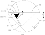
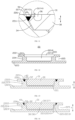
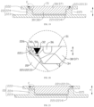
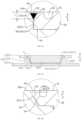
- a projection of the second weld face 32 in a plane parallel to the thickness direction X of the wall portion at least partially overlaps a projection of the first weld face 2211 in a plane parallel to the direction of the wall portion 211.
- a welding clearance 40 is formed in the overlapping region of the projections of the first weld face 2211 and the second weld face 32.
- the electrode terminal 22 is welded to the first blocking piece 30 within the welding clearance 40.
- the welding portion 50 may be fully located within the welding clearance 40; or, a part of the welding portion 50 is accommodated in the welding clearance 40, and another part of the welding portion extends out of the welding clearance 40 along a direction away from the interior of the battery cell 20 in the thickness direction X of the wall portion.
- the first weld face 2211 may be a closed-ring surface arranged around an axis parallel to the thickness direction X of the wall portion
- the second weld face 32 may be a closed-ring surface arranged around an axis parallel to the thickness direction X of the wall portion. Therefore, the welding clearance 40 may be an annular clearance around the axis parallel to the thickness direction X of the wall portion, and the welding portion 50 may be an annular structure located in the welding clearance 40 and consistent with the extension tendency of the welding clearance 40. In this way, the welding portion 50 can not only connect the electrode terminal 22 and the first blocking piece 30, but also play a role in sealing between the first blocking piece 30 and the electrode terminal 22.
- the sidewall of the receptacle 221 that accommodates the first blocking piece 30 includes a first weld face 2211.
- the first blocking piece 30 includes a second weld face 32.
- the first blocking piece 30 is welded to the electrode terminal 22 to form a welding portion 50.
- the welding portion 50 is connected to the first weld face 2211 and the second weld face 32 and at least partially located within the welding clearance 40. Therefore, the welding portion 50 may not extend out of the welding clearance 40 along a direction away from the interior of the battery cell 20, or may extend out of the welding clearance 40 by just a small amount along the direction away from the interior of the battery cell 20.
- the first blocking piece 30 includes a first surface 31.
- the first surface 31 is a surface, farthest away from the interior of the battery cell 20 along the thickness direction X of the wall portion, of the first blocking piece 30.
- the welding portion 50 does not exceed the first surface 31.
- the welding clearance 40 is of a specified depth along the thickness direction X of the wall portion.
- the welding portion 50 is located in the welding clearance 40, so that the welding portion 50 does not exceed the first surface 31 in the thickness direction X of the wall portion.
- one end, farthest away from the interior of the battery cell 20, of the welding portion 50 may be flush with the first surface 31; or, along the thickness direction X of the wall portion, one end, farthest away from the interior of the battery cell 20, of the welding portion 50 is closer to the interior of the battery cell 20 than the first surface 31, so that the welding portion 50 does not exceed the first surface 31 along a direction away from the battery cell 20.
- the welding portion 50 does not exceed the first surface 31. Therefore, in a case that the busbar component is connected to the first surface 31 of the first blocking piece 30to implement electrical connection between the battery cells 20, because the welding portion 50 does not exceed the first surface 31, the welding portion 50 will not interfere with the busbar component in a process of connecting the busbar component to the first surface 31 (for example, by welding). In this way, a stable connection is formed between the busbar component and the first surface 31, thereby forming a stable electrical connection between the first blocking piece 30 and the busbar component, and improving the stability of electrical energy output by the battery containing the battery cell 20.
- the welding clearance 40 is a structure of an equalized size.
- the size of the welding clearance 40 means a distance between the first weld face 2211 and the second weld face 32 along a direction perpendicular to the thickness direction X of the wall portion.
- the sizes at all positions on the welding clearance 40 are equalized, thereby facilitating control of the size of the welding portion 50, facilitating welding, and improving the welding quality.
- the welding clearance 40 is a structure of an unequalized size.
- the distance between the first weld face 2211 and the second weld face 32 gradually increases along a direction away from the interior of the battery cell 20. Therefore, the size of the welding clearance 40 at one end away from the interior of the battery cell 20 is larger than the size of the welding clearance 40 at one end close to the interior of the battery cell 20.
- both the large end and the small end of the second conical face are circles.
- the diameter of the large end of the second conical face is larger than the diameter of the small end of the second conical face.
- the axis of the circular conical face may coincide with the axis of the mounting hole 2111 or not.
- Both the first lateral wall face 2212 and the first lateral face 35 are cylindrical faces extending along the thickness direction X of the wall portion.
- the cylindrical faces are easier to process.
- a maximum dimension of the welding clearance 40 is L, satisfying: 0.1 mm ⁇ L ⁇ 0.7 mm.
- the maximum dimension L of the welding clearance 40 along the thickness direction X of the wall portion is a distance between one end farthest away from the interior of the battery cell 20 and one end closest to the interior of the battery cell 20 of the second weld face 32 along the thickness direction X of the wall portion.
- the maximum dimension L of the welding clearance 40 along the thickness direction X of the wall portion is a distance between one end of the first weld face 2211 and one end of the second weld face 32, where the one end of the first weld face is an end farthest away from the interior of the battery cell 20 along the thickness direction X of the wall portion, and the one end of the second weld face is an end closest to the interior of the battery cell 20 along the thickness direction X of the wall portion.
- the welding portion 50 may exceed the second surface 226 of the electrode terminal 22 along the thickness direction X of the wall portion, but without exceeding the first surface 31 of the first blocking piece 30.
- the dimension of the welding clearance 40 along the thickness direction X of the wall portion is relatively small. In order to prevent the welding portion 50 from exceeding the first surface 31 along the thickness direction X of the wall portion, the dimension of the welding portion 50 in the thickness direction X of the wall portion is also relatively small, thereby possibly leading to insufficient welding strength. If L is greater than 0.7 mm, the dimension of the welding clearance 40 along the thickness direction X of the wall portion is relatively large, thereby increasing the difficulty of welding. Therefore, the value of L is set to fall within the range of 0.1 mm ⁇ L ⁇ 0.7 mm, thereby making the dimension of the welding portion 50 meet the requirement on the welding strength for the electrode terminal 22 and the first blocking piece 30, and making the welding less difficult.
- the first blocking piece 30 includes a first surface 31.
- the first surface 31 is a surface, farthest away from the interior of the battery cell 20 along the thickness direction X of the wall portion, of the first blocking piece 30.
- a groove 36 is created on the first surface 31, and the groove 36 is arranged around an axis parallel to the thickness direction X of the wall portion.
- the groove 36 is an annular groove arranged around the axis parallel to the thickness direction X of the wall portion.
- the cross-section of the groove 36 may be U-shaped.
- the groove 36 can release the welding stress during the welding of the electrode terminal 22 and the first blocking piece 30, improve the welding quality, alleviate the deformation of the first blocking piece 30 and the electrode terminal 22 during the welding, improve the welding stress status in the circumferential direction of the first blocking piece 30, and reduce the risk caused by weld cracks.
- the receptacle 221 is a stepped groove.
- the receptacle 221 includes a first receptacle section 2213 and a second receptacle section 2214 connected to each other.
- the first receptacle section 2213 is farther away from the interior of the battery cell 20 than the second receptacle section 2214.
- At least a part of the first blocking piece 30 is accommodated in the first receptacle section 2213.
- the first weld face 2211 is at least a part of a sidewall of the first receptacle section 2213.
- first receptacle section 2213 extends to the second surface 226 of the electrode terminal 22.
- the second receptacle section 2214 is recessed from the bottom wall of the first receptacle section 2213 toward the interior of the battery cell 20.
- the structure of the first receptacle section 2213 may be the same as or different from the structure of the second receptacle section 2214.
- the first receptacle section 2213 and the second receptacle section 2214 may be circular grooves, square grooves, or the like.
- the first blocking piece 30 may be accommodated in the first receptacle section 2213 alone. Alternatively, a part of the first blocking piece 30 is accommodated in the first receptacle section 2213, and another part of the first blocking piece extends into the second receptacle section 2214.
- the first blocking piece 30 includes a body portion 37 and an extension portion 38 connected to each other.
- the body portion 37 is accommodated in the first receptacle section 2213 and abuts against a bottom wall of the first receptacle section 2213.
- the extension portion 38 extends from the body portion 37 into the second receptacle section 2214.
- the second weld face 32 is at least a part of an outer peripheral surface of the body portion 37.
- the first blocking piece 30 includes a second weld face 32 and a third conical face 34
- the second weld face 32 and the third conical face 34 together form an outer peripheral surface of the body portion 37.
- the first blocking piece 30 includes a second weld face 32 and a first lateral face 35
- the second weld face 32 and the first lateral face 35 together form the outer peripheral surface of the body portion 37.
- the first blocking piece 30 may include only a main portion accommodated in the first receptacle section 2213.
- the extension portion 38 includes a second lateral face 381 and a third surface 382 that is closest to the interior of the battery cell 20 along the thickness direction X of the wall portion.
- the second lateral face 381 is connected to the third surface 382 by a bevel face 383.
- the third surface 382 is also a surface, closest to the interior of the battery cell 20 along the thickness direction X of the wall portion, of the second blocking piece 70.
- the bevel face 383 may be a fillet face or a chamfer face.
- the third surface 382 is connected to the second lateral face 381 by a bevel face 383.
- the bevel face 383 not only eliminates the burrs at the end of the extension portion 38, but also plays a guiding role when the first blocking piece 30 enters the receptacle 221, and makes the first blocking piece 30 enter the receptacle 221 smoothly.
- the sidewall of the second receptacle section 2214 is spaced apart from the outer peripheral surface of the extension portion 38.
- the second receptacle section 2214 is in clearance fit with the extension portion 38.
- the sidewall of the second receptacle section 2214 is at a distance from the outer peripheral surface of the extension portion 38. In these embodiments, the sidewall of the second receptacle section 2214 is at a distance from the second lateral face 381 of the extension portion 38.
- the sidewall of the second receptacle section 2214 is spaced apart from the outer peripheral surface of the extension portion 38, thereby facilitating the assembling of the first blocking piece 30 and the electrode terminal 22.
- a distance between the sidewall of the second receptacle section 2214 and the outer peripheral surface of the extension portion 38 is h, satisfying: 0.03 mm ⁇ h ⁇ 0.1 mm.
- the distance h between the sidewall of the second receptacle section 2214 and the outer peripheral surface of the extension portion 38 is also the distance between the sidewall of the second receptacle section 2214 and the second lateral face 381 of the extension portion 38.
- the value of h may be 0.03 mm, 0.04 mm, 0.05 mm, 0.06 mm, 0.07 mm, 0.08 mm, 0.09 mm, 0.1 mm, or the like.
- h is less than 0.03 mm, the distance between the sidewall of the second receptacle section 2214 and the outer peripheral surface of the extension portion 38 is overly small and hardly controllable, imposes a higher requirement on the processing precision of the first blocking piece 30 and the electrode terminal 22, and increases the difficulty of processing. If h is greater than 0.1 mm, the distance between the sidewall of the second groove section 2214 and the outer peripheral surface of the extension portion 38 is overly large, thereby being prone to a relatively large displacement toward one side during the welding of the first blocking piece 30 and the electrode terminal 22, making the welding uneven, and impairing the welding quality.
- the value of h is set to fall within the range of 0.03 mm ⁇ h ⁇ 0.1 mm, thereby making the distance between the sidewall of the second receptacle section 2214 and the outer peripheral surface of the extension portion 38 fall within an easily controllable range, and also making the space relatively small in which the first blocking piece 30 is movable in the second receptacle section 2214 during the welding of the electrode terminal 22 and the first blocking piece 30, and in turn, improving the evenness and quality of the welding.
- the dimension n of the body portion 37 along the thickness direction X of the wall portion means a distance from the first surface 31 to a surface of the body portion 37 along the thickness direction X of the wall portion, where the surface abuts against the bottom wall of the first receptacle section 2213; or the dimension n means a distance between the first surface 31 and the bottom wall of the first receptacle section 2213.
- n may be 0.7 mm, 0.8 mm, 0.9 mm, 1.0 mm, 1.1 mm, 1.2 mm, 1.3 mm, 1.4 mm, 1.5 mm, or the like.
- an injection hole 228 is created on the electrode terminal 22.
- the injection hole 228 communicates with the receptacle 221 and the interior of the battery cell 20.
- the injection hole 228 is created on the bottom wall of the second receptacle section 2214, and penetrates the bottom wall of the second receptacle section 2214.
- the injection hole 228 may be created on the sidewall of the receptacle 221.
- the injection hole 228 is created on the sidewall of the second receptacle section 2214, and extends to one side of the second abutment portion 223, the side being oriented away from the connecting portion 224.
- the injection hole 228 is configured to allow an electrolyte solution to enter the shell 21. Specifically, the electrolyte solution enters the receptacle 221 and then is injected into the shell 21 through the injection hole 228.
- the second blocking piece 70 may be partially inserted in the injection hole 228, or fully inserted in the injection hole 228.
- no clearance portion 39 is disposed on the first blocking piece 30.
- the surface (the third surface 382), closest to the interior of the battery cell 20, of the first blocking piece 30 may abut on, or be spaced apart from, a surface of the second blocking piece 70, the surface being farthest away from the interior of the battery cell 20.
- the third surface 382 of the first blocking piece 30 abuts on, or is spaced apart from, a surface of the constraining portion 72, the surface being oriented away from the blocking portion 71.
- the extension portion 38 extends into the second receptacle section 2214.
- An outer peripheral surface of the body portion 37 includes a second weld face 32 and a third conical face 34. Both the second weld face 32 and the third conical face 34 are circular conical faces. A small end of the second weld face 32 is directly or indirectly connected to the first surface 31.
- An embodiment of this application provides a cylindrical battery.
- the cylindrical battery includes a shell 21, an electrode terminal 22, a first blocking piece 30, an electrode assembly 60, and a second blocking piece 70.
- the electrode terminal 22 is dielectrically disposed on a wall portion 211 of the shell 21.
- the electrode terminal 22 is configured to be electrically connected to a tab 61 of the electrode assembly 60.
- a receptacle 221 is created on a second surface 226 of the electrode terminal 22, the second surface being farthest away from the interior of the battery cell 20.
- the receptacle 221 is a stepped groove.
- the receptacle 221 includes a first receptacle section 2213 and a second receptacle section.
- the first blocking piece 30 includes a body portion 37 and an extension portion 38 connected to each other.
- the body portion 37 is accommodated in the first receptacle section 2213.
- a surface, connected to the extension portion 38, of the body portion 37 abuts against the bottom wall of the first receptacle section 2213.
- the extension portion 38 extends into the second receptacle section 2214.
- a first surface 31, farthest away from the interior of the battery cell 20, of the body portion 37 is configured to be welded to a busbar component.
- An outer peripheral surface of the body portion 37 includes a second weld face 32 and a first lateral face 35.
- the second weld face 32 is a circular conical face, and the second lateral face 381 is a cylindrical face.
- a small end of the second weld face 32 is directly or indirectly connected to the first surface 31.
- a large end of the second weld face 32 is connected to the first lateral face 35.
- the first lateral face 35 is arranged opposite to the first lateral wall face 2212.
- a welding clearance 40 is formed between a part of the first weld face 2211 and the second weld face 32.
- the electrode terminal 22 is welded to the first blocking piece 30 to form a welding portion 50 located in the welding clearance 40.
- the welding portion 50 is connected to the first weld face 2211 and the second weld face 32.
- the welding portion 50 does not exceed the first surface 31.
- Another part of the first weld face 2211 is arranged opposite to the third conical face 34.
- a third surface 382, oriented away from the body portion 37, of the extension portion 38 is connected to the outer peripheral surface (a second lateral face 381) of the extension portion 38 by a bevel face 383.
- An injection hole 228 is created on a bottom wall of the second receptacle section 2214.
- a blocking portion 71 of the second blocking piece 70 is inserted in the injection hole 228.
- a constraining portion 72 of the second blocking piece 70 is connected to one end of the blocking portion 71 and located in the second receptacle section 2214.
- the constraining portion 72 abuts against the bottom wall of the second receptacle section 2214.
- a clearance portion 39 is disposed on the third surface 382 of the extension portion 38. At least a part of the constraining portion 72 is accommodated in the clearance portion 39.
Landscapes
- Chemical & Material Sciences (AREA)
- Chemical Kinetics & Catalysis (AREA)
- Electrochemistry (AREA)
- General Chemical & Material Sciences (AREA)
- Sealing Battery Cases Or Jackets (AREA)
Abstract
Description
- This application relates to the technical field of batteries, and in particular, to a battery cell, a battery, and an electrical device.
- In the megatrend of pursuing energy conservation and emission reduction, batteries are widely used in electrical devices such as mobile phones, computers, and electric vehicles to provide electrical energy for the electrical devices. The stability of power supplied by a battery to an electrical device is essential to the implementation of the functionality of the electrical device. Therefore, how to enhance the stability of power supplied by the battery is a pressing technical challenge in this technical field.
- Some embodiments of this application provide a battery cell, a battery, and an electrical device to improve the stability of electrical energy output by the battery.
- According to a first aspect, an embodiment of this application provides a battery cell, including a shell, an electrode terminal, and a first blocking piece. The shell includes a wall portion. The electrode terminal is disposed on the wall portion. A receptacle is disposed on a surface of the electrode terminal, and the surface is oriented away from an interior of the battery cell along a thickness direction of the wall portion. A sidewall of the receptacle includes a first weld face. The first blocking piece is at least partially accommodated in the receptacle. The first blocking piece includes a second weld face. A welding clearance is formed between the second weld face and the first weld face. The first blocking piece is welded to the electrode terminal to form a welding portion. The welding portion is connected to the first weld face and the second weld face and at least partially located within the welding clearance.
- In the above technical solution, the sidewall of the receptacle that accommodates the first blocking piece includes a first weld face. The first blocking piece includes a second weld face. The first blocking piece is welded to the electrode terminal to form a welding portion. The welding portion is connected to the first weld face and the second weld face and at least partially located within the welding clearance. Therefore, the welding portion may not extend out of the welding clearance along a direction away from the interior of the battery cell, or may extend out of the welding clearance by just a small amount along the direction away from the interior of the battery cell. In this way, in a case that the busbar component is connected to the first blocking piece to implement electrical connection between the battery cells, when the busbar component is connected to the first blocking piece (for example, by welding), because the welding portion does not exceed the welding clearance or exceeds the welding clearance by just very small amount, the interference between the welding portion and the busbar component is alleviated, and a stable connection can be favorably formed between the busbar component and the first blocking piece, thereby forming a stable electrical connection between the first blocking piece and the busbar component, and improving the stability of electrical energy output by the battery containing the battery cell.
- In some embodiments in the first aspect of this application, the first blocking piece includes a first surface. The first surface is a surface, farthest away from the interior of the battery cell along the thickness direction of the wall portion, of the first blocking piece. The welding portion does not exceed the first surface.
- In the above technical solution, the welding portion does not exceed the first surface. Therefore, in a case that the busbar component is connected to the first surface of the first blocking piece to implement electrical connection between the battery cells, because the welding portion does not exceed the first surface, the welding portion will not interfere with the busbar component in a process of connecting the busbar component to the first surface (for example, by welding). In this way, a stable connection is formed between the busbar component and the first surface, thereby forming a stable electrical connection between the first blocking piece and the busbar component, and improving the stability of electrical energy output by the battery containing the battery cell.
- In some embodiments in the first aspect of this application, in the thickness direction of the wall portion, the welding clearance gradually increases along a direction away from the interior of the battery cell.
- In the above technical solution, in the thickness direction of the wall portion, the welding clearance gradually increases along the direction away from the interior of the battery cell. Therefore, along the thickness direction of the wall portion, the dimension of the welding clearance is relatively large at an end close to the first surface, thereby providing a relatively large space for a welding gun, facilitating the welding gun to enter the welding clearance, and facilitating welding.
- In some embodiments in the first aspect of this application, along the thickness direction of the wall portion, the electrode terminal includes a second surface farthest away from the interior of the battery cell. The receptacle is recessed from the second surface toward the interior of the battery cell. The first weld face is at an obtuse angle to the second surface.
- In the above technical solution, the first weld face is at an obtuse angle to the second surface. Therefore, the receptacle forms a relatively large aperture at a position near the second surface, thereby facilitating the entry of the first blocking piece into the receptacle from the receptacle aperture on the second surface.
- In some embodiments in the first aspect of this application, an angle between the first weld face and the second surface is θ, satisfying: 110° ≤ θ ≤ 160°.
- In the above technical solution, if θ is overly small, the relatively large receptacle aperture formed at the position near the second surface is not a favorable option for the dimension of the electrode terminal of an actual product. If θ is overly large, a relatively large aperture of the receptacle can be formed at a position near the second surface to facilitate the entry of the first blocking piece into the receptacle, but the large aperture may impair the structural strength of the electrode terminal. Therefore, the angle falling within the range of 110° ≤ θ ≤ 160° not only produces a relatively large aperture of the receptacle at a position near the second surface and facilitates entry of the first blocking piece into the receptacle, but also makes the structural strength of the electrode terminal meet actual needs.
- In some embodiments in the first aspect of this application, the first weld face is connected to the second surface.
- In the above technical solution, the first weld face is connected to the second surface, so that the welding clearance extends from the second surface to the interior of the battery cell, thereby making the welding operation more convenient.
- In some embodiments in the first aspect of this application, the first blocking piece includes the first surface. The first surface is a surface, farthest away from the interior of the battery cell along the thickness direction of the wall portion, of the first blocking piece. The first surface is flush with the second surface.
- In the above technical solution, the first surface is flush with the second surface, thereby reducing the dimension of an integrated structure formed by the electrode terminal and the first blocking piece along the thickness direction of the wall portion, and in turn, reducing the dimension of the battery cell along the thickness direction of the wall portion.
- In some embodiments in the first aspect of this application, the first weld face is a first conical face. Along the thickness direction of the wall portion, a large end of the first weld face is farther away from the interior of the battery cell than a small end of the first weld face.
- In the above technical solution, the first weld face is a first conical face, and the large end of the first weld face is farther away from the interior of the battery cell than the small end of the first weld face. In this way, the size of the aperture of the receptacle is relatively large at a position near a side of the electrode terminal, the side being oriented away from the interior of the battery cell, thereby facilitating the entry of the first blocking piece into the receptacle.
- In some embodiments in the first aspect of this application, the first conical face is a circular conical face.
- In the above technical solution, the first conical face is a circular conical face, thereby making the processing operation easier. During the entry of the first blocking piece into the receptacle, the structure of the circular conical face keeps the same along the circumferential direction. Therefore, the requirement on the positioning precision of the first blocking piece relative to the receptacle is not high, thereby facilitating the assembling of the first blocking piece and the electrode terminal, and improving the assembling efficiency.
- In some embodiments in the first aspect of this application, the first blocking piece includes a first surface. The first surface is a surface, farthest away from the interior of the battery cell along the thickness direction of the wall portion, of the first blocking piece. The second weld face is at an obtuse angle to the first surface.
- In the above technical solution, the second weld face is at an obtuse angle to the first surface, thereby facilitating formation of a relatively wide opened welding clearance on a side oriented away from the interior of the battery cell, facilitating the entry of the welding gun into the welding clearance, and facilitating the welding between the electrode terminal and the first blocking piece.
- In some embodiments in the first aspect of this application, the second weld face is connected to the first surface.
- In the above technical solution, the second weld face is connected to the first surface, so that the welding clearance extends from the first surface to the interior of the battery cell, thereby making the welding operation more convenient.
- In some embodiments in the first aspect of this application, the second weld face is a second conical face. Along the thickness direction of the wall portion, a small end of the second weld face is farther away from the interior of the battery cell than a large end of the second weld face.
- In the above technical solution, the second weld face is a second conical face, and the small end of the second weld face is farther away from the interior of the battery cell than the large end of the second weld face, thereby facilitating formation of a relatively wide opened welding clearance, and facilitating the welding between the electrode terminal and the first blocking piece.
- In some embodiments in the first aspect of this application, the first weld face is a first conical face. Along the thickness direction of the wall portion, a large end of the first weld face is farther away from the interior of the battery cell than a small end of the first weld face. The first blocking piece further includes a third conical face. The third conical face is disposed opposite to the first conical face. The third conical face is connected to a large end of the second conical face.
- In the above technical solution, the first weld face is a first conical face, and the large end of the first weld face is farther away from the interior of the battery cell than the small end of the first weld face. The second conical face and a part of the first conical face form the welding clearance. In the thickness direction of the wall portion, the welding clearance gradually increases along the direction away from the interior of the battery cell. Therefore, the dimension of the welding clearance is relatively large at an end close to the first surface, thereby providing a relatively large space for a welding gun, facilitating the welding gun to enter the welding clearance, and facilitating welding. The third conical face is disposed opposite to the first conical face, thereby making the shape of the first blocking piece fit the shape of the receptacle more closely, and facilitating assembling.
- In some embodiments in the first aspect of this application, the second conical face is a circular conical face; and/or the third conical face is a circular conical face.
- In the above technical solution, during actual production, the circular conical face is easier to process. The second conical face and/or the third conical face is a circular conical face. Therefore, during the entry of the first blocking piece into the receptacle, the structure of the circular conical face keeps the same along the circumferential direction. Therefore, the requirement on the positioning precision of the first blocking piece relative to the receptacle is not high, thereby facilitating the assembling of the first blocking piece and the electrode terminal, and improving the assembling efficiency.
- In some embodiments in the first aspect of this application, the first blocking piece further includes a first lateral face. The first lateral face is connected to the large end of the second weld face. The sidewall of the receptacle further includes a first lateral wall face. Along the thickness direction of the wall portion, the first lateral wall face is closer to the interior of the battery cell than the first weld face. The first lateral wall face is connected to one end of the first weld face, the end being close to the interior of the battery cell. The first lateral wall face is arranged opposite to the first lateral face. Both the first lateral wall face and the first lateral face are cylindrical faces extending along the thickness direction of the wall portion.
- In the above technical solution, both the first lateral wall face and the first lateral face are cylindrical faces extending along the thickness direction of the wall portion. The cylindrical faces are easier to process.
- In some embodiments in the first aspect of this application, along the thickness direction of the wall portion, a maximum dimension of the welding clearance is L, satisfying: 0.1 mm ≤ L ≤ 0.7 mm.
- In the above technical solution, if L is greater than 0.1 mm, the dimension of the welding clearance along the thickness direction of the wall portion is relatively small. In order to prevent the welding portion from exceeding the first surface along the thickness direction of the wall portion, the dimension of the welding portion in the thickness direction of the wall portion is also relatively small, thereby possibly leading to insufficient welding strength. If L is greater than 0.7 mm, the dimension of the welding clearance along the thickness direction of the wall portion is relatively large, thereby increasing the difficulty of welding. Therefore, the value of L is set to fall within the range of 0.1 mm ≤ L ≤ 0.7 mm, thereby making the dimension of the welding portion meet the requirement on the welding strength for the electrode terminal and the first blocking piece, and making the welding less difficult.
- In some embodiments in the first aspect of this application, the first blocking piece includes the first surface. The first surface is a surface, farthest away from the interior of the battery cell along the thickness direction of the wall portion, of the first blocking piece. A groove is further created on the first surface. The groove is arranged around an axis parallel to the thickness direction of the wall portion.
- In the above technical solution, the groove can release the welding stress during the welding of the electrode terminal and the first blocking piece, improve the welding quality, and alleviate the deformation of the first blocking piece and the electrode terminal during the welding.
- In some embodiments in the first aspect of this application, the receptacle is a stepped groove. The receptacle includes a first receptacle section and a second receptacle section connected to each other. The first receptacle section is farther away from the interior of the battery cell than the second receptacle section. At least a part of the first blocking piece is accommodated in the first receptacle section. The first weld face is at least a part of a sidewall of the first receptacle section.
- In the above technical solution, the receptacle is a stepped groove, thereby not only reducing the dimension of the electrode terminal along the thickness direction of the wall portion, facilitating the welding of the electrode terminal to a tab inside the battery cell, but also reducing the weight of the electrode terminal, and in turn, reducing the weight of the battery cell.
- In some embodiments in the first aspect of this application, the first blocking piece includes a body portion and an extension portion connected to each other. The body portion is accommodated in the first receptacle section and abuts against a bottom wall of the first receptacle section. The extension portion extends from the body portion into the second receptacle section. The second weld face is at least a part of an outer peripheral surface of the body portion.
- In the above technical solution, the body portion is accommodated in the first receptacle section and abuts against the bottom wall of the first receptacle section, thereby restricting the first blocking piece from further moving closer to the interior of the battery cell in the thickness direction of the wall portion, and facilitating electrical connection between the busbar component and the first blocking piece. The extension portion extends from the body portion into the second receptacle section, and is in positional fit with the second receptacle section, thereby favorably maintaining a stable relative positional relationship between the first blocking piece and the electrode terminal.
- In some embodiments in the first aspect of this application, the extension portion includes a second lateral face and a third surface closest to the interior of the battery cell along the thickness direction of the wall portion. The second lateral face is connected to the third surface by a bevel face.
- In the above technical solution, the third surface is connected to the second lateral face by a bevel face. The bevel face not only eliminates the burrs at the end of the extension portion, but also plays a guiding role when the first blocking piece enters the receptacle, and makes the first blocking piece enter the receptacle smoothly.
- In some embodiments in the first aspect of this application, a sidewall of the second receptacle section is spaced apart from an outer peripheral surface of the extension portion.
- In the above technical solution, the sidewall of the second receptacle section is spaced apart from the outer peripheral surface of the extension portion, thereby facilitating the assembling of the first blocking piece and the electrode terminal.
- In some embodiments in the first aspect of this application, a distance between the sidewall of the second receptacle section and the outer peripheral surface of the extension portion is h, satisfying: 0.03 mm ≤ h ≤ 0.1 mm.
- In the above technical solution, if h is less than 0.03 mm, the distance between the sidewall of the second receptacle section and the outer peripheral surface of the extension portion is overly small and hardly controllable, imposes a higher requirement on the processing precision of the first blocking piece and the electrode terminal, and increases the difficulty of processing. If h is greater than 0.1 mm, the distance between the sidewall of the second groove section and the outer peripheral surface of the extension portion is overly large, thereby being prone to a relatively large displacement toward one side during the welding of the first blocking piece and the electrode terminal, making the welding uneven, and impairing the welding quality. Therefore, the value of h is set to fall within the range of 0.03 mm ≤ h ≤ 0.1 mm, thereby making the distance between the sidewall of the second receptacle section and the outer peripheral surface of the extension portion fall within an easily controllable range, and also making the space relatively small in which the first blocking piece is movable in the second receptacle section during the welding of the electrode terminal and the first blocking piece, and in turn, improving the evenness and quality of the welding.
- In some embodiments in the first aspect of this application, along the thickness direction of the wall portion, a dimension of the body portion is n, satisfying: 0.7 mm ≤ n ≤ 1.5 mm.
- In the above technical solution, if n is less than 0.7 mm, the strength of the body portion is not enough to meet the actual use requirements. If n is greater than1.5 mm, the dimension of the body portion along the thickness direction of the wall portion is overlarge, thereby increasing the size of the battery cell. Therefore, the value of n is set to fall within the range of 0.7 mm ≤ n ≤ 1.5 mm, thereby not only making the dimension of the battery cell along the thickness direction of the wall portion fall within a reasonable range, but also ensuring sufficient structural strength of the body portion.
- In some embodiments in the first aspect of this application, an injection hole is created on the electrode terminal. The injection hole communicates with the receptacle and the interior of the battery cell.
- In the above technical solution, the injection hole is created on the electrode terminal, thereby making the processing operation more convenient, and avoiding positioning of the injection hole on the shell that impairs the structural strength of the shell.
- In some embodiments in the first aspect of this application, the battery cell further includes a second blocking piece. At least a part of the second blocking piece is inserted in the injection hole to block the injection hole.
- In the above technical solution, the second blocking piece blocks the injection hole, thereby reducing the risk of an electrolyte leak of the battery cell, and reducing the risk that the welding slag falls from the injection hole into the battery cell during the welding of the first blocking piece and the electrode terminal. The second blocking piece can also play a role in heat insulation and reduce the damage caused by high temperature to the internal structure and materials of the battery cell during the welding of the first blocking piece and the electrode terminal.
- In some embodiments in the first aspect of this application, the second blocking piece includes a blocking portion and a constraining portion. The blocking portion is inserted in the injection hole. The constraining portion is connected to one end of the blocking portion and located in the receptacle. The constraining portion is configured to abut against a bottom wall of the receptacle.
- In the above technical solution, the constraining portion of the second blocking piece abuts against the bottom wall of the receptacle, thereby constraining the second blocking piece from moving toward the interior of the battery cell, and reducing the risk that the second blocking piece falls into the interior of the battery cell.
- In some embodiments in the first aspect of this application, a clearance portion is disposed on the first blocking piece. The clearance portion is configured to accommodate a part of the second blocking piece.
- In the above technical solution, the clearance portion can reduce the risk of interference between the second blocking piece and the first blocking piece. The clearance portion accommodates a part of the second blocking piece, that is, a part of the second blocking piece is embedded in the first blocking piece, thereby reducing the size of the integrated structure formed by the first blocking piece and the second blocking piece.
- According to a second aspect, an embodiment of this application further provides a battery, including the battery cell disclosed in an embodiment of the first aspect.
- In the above technical solution, a welding portion is formed by welding the electrode terminal to the first blocking piece in the battery cell disclosed in an embodiment of the first aspect, and the welding portion does not exceed the first surface of the first blocking piece. Therefore, in a process of connecting the busbar component to the first surface (for example, by welding), the welding portion will not interfere with the busbar component. In this way, a stable connection is formed between the busbar component and the first surface, thereby forming a stable electrical connection between the first blocking piece and the busbar component, and improving the stability of electrical energy output by the battery.
- According to a third aspect, an embodiment of this application further provides an electrical device, including the battery disclosed in an embodiment of the second aspect.
- In the above technical solution, the battery disclosed in an embodiment of the second aspect can stably output electric energy, thereby ensuring the electrical device to work stably.
- To describe technical solutions in embodiments of this application more clearly, the following outlines the drawings to be used in the embodiments. Understandably, the following drawings show merely some embodiments of this application, and therefore, are not intended to limit the scope. A person of ordinary skill in the art may derive other related drawings from the drawings without making any creative efforts.
-
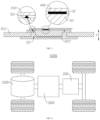
FIG. 1 is a schematic diagram of welding a first blocking piece and a busbar component in the related art; -
FIG. 2 is a schematic structural diagram of a vehicle according to some embodiments of this application; -
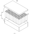
FIG. 3 is an exploded view of a battery according to some embodiments of this application; -
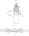
FIG. 4 is an exploded view of a battery cell according to some embodiments of this application; -
FIG. 5 is a schematic diagram of a wall portion, an electrode terminal, and a first blocking piece assembled together according to some embodiments of this application; -
FIG. 6 is a close-up view of a part A shown inFIG. 5 ; -
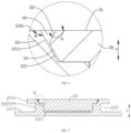
FIG. 7 is a schematic structural diagram of the electrode terminal and first blocking piece shown inFIG. 5 that are welded together; -
FIG. 8 is a close-up view of a part B shown inFIG. 7 ; -
FIG. 9 is a schematic structural diagram of an electrode terminal according to some embodiments of this application; -
FIG. 10 is a schematic structural diagram of an electrode terminal and a first blocking piece welded together according to some other embodiments of this application; -
FIG. 11 is a close-up view of a part C shown inFIG. 10 ; -
FIG. 12 is a cross-sectional view of an electrode terminal according to some embodiments of this application; -
FIG. 13 is a schematic diagram of an electrode terminal and a first blocking piece welded together according to still some other embodiments of this application; -
FIG. 14 is a schematic diagram of an electrode terminal and a first blocking piece welded together according to still some other embodiments of this application; -
FIG. 15 is a cross-sectional view of a first blocking piece according to some embodiments of this application; -
FIG. 16 is a cross-sectional view of a first blocking piece according to some other embodiments of this application; -
FIG. 17 is a schematic diagram of an electrode terminal and a first blocking piece welded together according to still some other embodiments of this application; -
FIG. 18 is a close-up view of a part D shown inFIG. 17 ; -
FIG. 19 is a schematic diagram of an electrode terminal and a first blocking piece welded together according to still some other embodiments of this application; -
FIG. 20 is a close-up view of a part E shown inFIG. 19 ; -
FIG. 21 is a schematic diagram of an electrode terminal and a first blocking piece welded together according to still some other embodiments of this application; -
FIG. 22 is a close-up view of a part F shown inFIG. 21 ; -
FIG. 23 is a schematic diagram of an electrode terminal and a first blocking piece assembled together according to still some embodiments of this application; -
FIG. 24 is a close-up view of a part G shown inFIG. 23 ; -
FIG. 25 is a schematic diagram of fitting an electrode terminal to a first blocking piece according to still some other embodiments of this application; -
FIG. 26 is a schematic structural diagram of an electrode terminal and a first blocking piece fitted together according to still some other embodiments of this application; and -
FIG. 27 is a schematic structural diagram of an electrode terminal and a first blocking piece fitted together according to still some other embodiments of this application. - List of reference numerals: 1000-vehicle; 100-battery; 10-box; 11-first part; 12-second part; 20-battery cell; 21-shell; 211', 211-wall portion; 2111-mounting hole; 212 -housing; 2121-opening; 213-end cap; 22', 22-electrode terminal; 221', 221-receptacle; 2211-first weld face; 2212-first lateral wall face; 2213-first receptacle section; 2214-second receptacle section; 222-first abutment portion; 223-second abutment portion; 224-connecting portion; 225-annular snap slot; 226-second surface; 227-first transitional face; 228-injection hole; 23-insulator; 30', 30-first blocking piece; 31', 31-first surface; 32-second weld face; 33-second transitional face; 34-third conical face; 35-first lateral face; 36-groove; 361-first section; 362-second section; 37-body portion; 38-extension portion; 381-second lateral face; 382-third surface; 383-bevel face; 39-clearance portion; 40-welding clearance; 50', 50-welding portion; 60-electrode assembly; 61-tab; 70-second blocking piece; 71-blocking portion; 72-constraining portion; 200-controller; 300-motor; X-thickness direction of wall portion; Y1-first intersection line; Y2-second intersection line; Y3-third intersection line; Y4-fourth intersection line; 400'-busbar component.
- To make the objectives, technical solutions, and advantages of some embodiments of this application clearer, the following gives a clear and complete description of the technical solutions in some embodiments of this application with reference to the drawings in some embodiments of this application. Apparently, the described embodiments are merely a part of but not all of the embodiments of this application. Generally, the components of some embodiments of this application, which are described and illustrated in the drawings hereto, may be arranged and designed in a variety of different configurations.
- Therefore, the following detailed description of some embodiments of this application provided with reference to the drawings is not intended to limit the scope of this application as claimed, but merely represents selected embodiments of this application. All other embodiments derived by a person of ordinary skill in the art based on the embodiments of this application without making any creative efforts still fall within the protection scope of this application.
- It is hereby noted that to the extent that no conflict occurs, embodiments of this application and the features in the embodiments may be combined with each other.
- It is hereby noted that similar reference numerals and letters indicate similar items in the following drawings. Therefore, once an item is defined in one drawing, the item does not need to be further defined or construed in subsequent drawings.
- In the description of the embodiments of this application, it is hereby noted that an indicated direction or positional relationship is a direction or positional relationship based on illustration in the drawings, or a direction or positional relationship by which a product in use according to this application is usually placed, or a direction or positional relationship commonly understood by a person skilled in the art, and is merely intended for ease or brevity of describing this application, but does not indicate or imply that the indicated apparatus or component is necessarily located in the specified direction or constructed or operated in the specified direction. Therefore, the indicated direction or positional relationship is never to be understood as a limitation on this application. In addition, the terms "first", "second", "third", and so on are merely used for differentiated description, but not to be understood as indicating or implying order of precedence.
- Currently, as can be seen from the market trend, the application of power batteries is increasingly extensive. Power batteries are not only used in energy storage power systems such as hydro, thermal, wind, and solar power stations, but also widely used in electric means of transport such as electric bicycles, electric motorcycles, and electric vehicles, and used in many other fields such as military equipment and aerospace. The market demand for
power batteries 100 keeps soaring with the expansion of the application fields of the power batteries. - The battery mentioned in embodiments of this application means a unitary physical module that includes one or more battery cells to provide a higher voltage and a higher capacity. For example, the battery mentioned in this application may include a battery module, a battery pack, or the like. A battery typically includes a box configured to package one or more battery cells. The box prevents liquid or other foreign matters from affecting the charging or discharging of the battery cells.
- "A plurality of" referred to in this application means two or more (including two).
- In this application, a battery cell may include a lithium-ion secondary battery, a lithium-ion primary battery, a lithium-sulfur battery, a sodium-lithium-ion battery, a sodium-ion battery, a magnesium-ion battery, or the like, without being limited in embodiments of this application. The battery cell may be in various shapes such as cylindrical, flat, cuboidal or other shapes. The shape of the battery cell is not limited herein. Depending on the form of packaging, the battery cell is typically classed into three types: cylindrical battery cell, prismatic battery cell, and pouch-type battery cell, without being limited in embodiments of this application.
- In an embodiment in which the battery includes a plurality of battery cells, the plurality of battery cells may be connected in series, parallel, or series-and-parallel pattern by a busbar component. The series-and-parallel pattern means a combination of series connection and parallel connection of the plurality of battery cells.
- A battery cell 20' includes a shell 21', an electrode terminal 22', and an electrode assembly 60'. The electrode assembly 60' is accommodated in the shell 21'. The electrode terminal 22' is disposed on a wall portion 211' of the shell 21'. The electrode terminal 22' is configured to be electrically connected to the electrode assembly 60'. A busbar component 400' is electrically connected to the electrode terminal 22' of the battery cell 20' to implement series, parallel, or series-and-parallel connection of the plurality of
battery cells 20. - As shown in
FIG. 1 , the busbar component 400' is typically not directly connected to the electrode terminal 22'. Instead, a first blocking piece 30' is welded onto the electrode terminal 22', and the busbar component 400' is directly connected to the first blocking piece 30', so that the electrode terminal 22' is electrically connected to the busbar component 400' by the first blocking piece 30'. In order to reduce the size of an integrated structure formed by the electrode terminal 22' and the first blocking piece 30', a receptacle 221' is disposed on a surface of the electrode terminal 22', where the surface is oriented away from the interior of the battery cell 20' along a thickness direction X of the wall portion. At least a part of the first blocking piece 30' is accommodated in the receptacle 221'. Along the thickness direction X of the wall portion, a first surface 31', farthest away from the interior of the battery cell 20', of the first blocking piece 30', is configured to be welded to the busbar component 400' to implement the electrical connection. - The inventor hereof finds that, as shown in
FIG. 1 , after the first blocking piece 30' is welded to the electrode terminal 22', a welding portion 50' is formed. The welding portion 50' protrudes beyond the first surface 31' of the first blocking piece 30'. During welding of the busbar component 400' to the first surface 31', the busbar component 400' props one side of the busbar component 400', the side being oriented toward the first blocking piece 30'. This impairs the quality of welding between the busbar component 400' and the first blocking piece 30', and may lead to a cold solder joint between the busbar component 400' and the first surface 31', thereby making the electrical connection between the first blocking piece 30' and the busbar component 400' unstable or even failed. - Based on the above considerations, in order to alleviate the potential problem of a cold solder joint between the busbar component and the first surface caused by the phenomenon that the welding portion formed by the welding of the electrode terminal and the first blocking piece protrudes beyond the first surface of the first blocking piece, the inventor designs a battery cell after in-depth research. In the battery cell, along the thickness direction of the wall portion of the shell, a first weld face is included on a sidewall of a receptacle disposed on a surface of the electrode terminal, the surface being oriented away from the interior of the battery cell. The first blocking piece includes a second weld face. A welding clearance is formed between the second weld face and the first weld face. The first blocking piece is welded to the electrode terminal to form a welding portion. The welding portion is connected to the first weld face and the second weld face, and is at least partially located in the welding clearance.
- The sidewall of the receptacle that accommodates the first blocking piece includes a first weld face. The first blocking piece includes a second weld face. The first blocking piece is welded to the electrode terminal to form a welding portion. The welding portion is connected to the first weld face and the second weld face and at least partially located within the welding clearance. Therefore, the welding portion may not extend out of the welding clearance along a direction away from the interior of the battery cell, or extends out of the welding clearance by just a small amount along the direction away from the interior of the battery cell. In this way, in a case that the busbar component is connected to the first blocking piece to implement electrical connection between the battery cells, due to the fact that the welding portion does not exceed the first surface, when the busbar component is connected to the first blocking piece (for example, by welding), because the welding portion does not exceed the welding clearance or exceeds the welding clearance by just very small amount, the interference between the welding portion and the busbar component is alleviated, and a stable connection can be favorably formed between the busbar component and the first blocking piece, thereby forming a stable electrical connection between the first blocking piece and the busbar component, and improving the stability of electrical energy output by the battery containing the battery cell.
- The battery cell disclosed in this embodiment of this application is applicable to, but without being limited to, electrical devices such as a vehicle, watercraft, or aircraft. A power supply system of the electrical devices may be formed by using the battery cell, the battery, and the like disclosed herein, so as to improve the stability of electrical energy output by the battery.
- An embodiment of this application provides an electrical device powered by a battery. The electrical device may be, but is not limited to, a mobile phone, a tablet, a laptop computer, an electric toy, an electric tool, an electric power cart, an electric vehicle, a ship, a spacecraft, or the like. The electric toy may include stationary or mobile electric toys, such as a game console, an electric car toy, an electric ship toy, an electric airplane toy, and the like. The spacecraft may include an airplane, a rocket, a space shuttle, a spaceship, and the like.
- For ease of description in the following embodiments, a
vehicle 1000 is used as an example of the electrical device according to an embodiment of this application. - Referring to
FIG. 2, FIG. 2 is a schematic structural diagram of avehicle 1000 according to some embodiments of this application. Thevehicle 1000 may be an oil-fueled vehicle, a natural gas vehicle, or a new energy vehicle. The new energy vehicle may be a battery electric vehicle, a hybrid electric vehicle, a range-extended electric vehicle, or the like. Abattery 100 is disposed inside thevehicle 1000. Thebattery 100 may be disposed at the bottom, front, or rear of thevehicle 1000. Thebattery 100 may be configured to supply power to thevehicle 1000. For example, thebattery 100 may serve as an operating power supply of thevehicle 1000. Thevehicle 1000 may further include acontroller 200 and amotor 300. Thecontroller 200 is configured to control thebattery 100 to supply power to themotor 300, for example, to meet electrical energy requirements in starting, navigating, or running thevehicle 1000. - In some embodiments of this application, the
battery 100 serves not only as an operating power supply of thevehicle 1000, but may also serve as a driving power supply of thevehicle 1000 to provide driving power for thevehicle 1000 in place of or partly in place of fuel oil or natural gas. - Referring to
FIG. 3, FIG. 3 is an exploded view of abattery 100 according to some embodiments of this application. Thebattery 100 includes a box 10 and abattery cell 20. Thebattery cell 20 is accommodated in the box 10. The box 10 is configured to provide an accommodation space for thebattery cell 20. The box 10 may be in various structures. In some embodiments, the box 10 may include a first part 11 and a second part 12. The first part 11 and the second part 12 fit and cover each other. The first part 11 and the second part 12 together define an accommodation space configured to accommodate thebattery cell 20. The second part 12 may be a hollow structure opened at one end to form an accommodation cavity for accommodating thebattery cell 20. The first part 11 may be a plate-like structure. The first part 11 fits the opening of the second part 12 so that the first part 11 and the second part 12 together define the accommodation space. Alternatively, both the first part 11 and the second part 12 may be hollow structures opened at one side to form an accommodation cavity for accommodating thebattery cell 20. The opening of the first part 11 fits the opening of the second part 12. Definitely, the box 10 formed by the first part 11 and the second part 12 may be in various shapes, such as a cylinder or a cuboid. - The
battery 100 may contain a plurality ofbattery cells 20. The plurality ofbattery cells 20 may be connected in series, parallel, or series-and-parallel pattern. The series-and-parallel pattern means a combination of series connection and parallel connection of the plurality ofbattery cells 20. The plurality ofbattery cells 20 may be directly connected in series, parallel, or series-and-parallel pattern, and then the whole of the plurality ofbattery cells 20 may be accommodated in the box 10. Alternatively, to make up abattery 100, the plurality ofbattery cells 20 may be connected in series, parallel, or series-and-parallel pattern to form a battery module first, and then a plurality of battery modules are connected in series, parallel, or series-and-parallel pattern to form a whole and accommodated in the box 10. Thebattery 100 may further include other structures. For example, thebattery 100 may include a busbar component (not shown inFIG. 2 ). The busbar component is configured to implement an electrical connection between the plurality ofbattery cells 20. - Each
battery cell 20 may be, but is not limited to, a secondary battery or primary battery; or, may be a lithium-sulfur battery, a sodium-ion battery, or a magnesium-ion battery. Thebattery cell 20 may be in a shape such as a cylinder, a flat body, a cuboid, or other shapes. - As shown in
FIG. 4 to FIG. 8 , in some embodiments, thebattery cell 20 includes ashell 21, anelectrode terminal 22, and afirst blocking piece 30. Theshell 21 includes awall portion 211. Theelectrode terminal 22 is disposed on thewall portion 211. Areceptacle 221 is disposed on a surface of theelectrode terminal 22, and the surface is oriented away from the interior of thebattery cell 20 along a thickness direction X of the wall portion. A sidewall of thereceptacle 221 includes afirst weld face 2211. Thefirst blocking piece 30 is at least partially accommodated in thereceptacle 221. Thefirst blocking piece 30 includes asecond weld face 32. Awelding clearance 40 is formed between thesecond weld face 32 and thefirst weld face 2211. Thefirst blocking piece 30 is welded to theelectrode terminal 22 to form awelding portion 50. Thewelding portion 50 is connected to thefirst weld face 2211 and thesecond weld face 32 and at least partially located within thewelding clearance 40. - As shown
FIG. 4 , theshell 21 includes ahousing 212 and anend cap 213. Thehousing 212 includes anopening 2121 at one end. Theend cap 213 is configured to seal theopening 2121 of thehousing 212, so that theend cap 213 and thehousing 212 together form an accommodation space configured to accommodate theelectrode assembly 60. Without limitation, the shape of theend cap 213 may be adapted to the shape of thehousing 212 to fit thehousing 212. Optionally, theend cap 213 may be made of a material of appropriate hardness and strength (such as aluminum alloy), so that theend cap 213 is not prone to deform when squeezed or impacted. In this way, thebattery cell 20 achieves higher structural strength and higher safety performance. - The
housing 212 is a component configured to fit theend cap 213 to form an internal environment of thebattery cell 20. The formed internal environment may be used to accommodate theelectrode assembly 60, an electrolytic solution, and other components. Thehousing 212 and theend cap 213 may be stand-alone components. Anopening 2121 may be created on thehousing 212. At theopening 2121, theend cap 213 fits and covers theopening 2121 to form the internal environment of thebattery cell 20. Without limitation, theend cap 213 and thehousing 212 may be integrated instead. Specifically, theend cap 213 and thehousing 212 may form a common connection interface before other components are put into the housing. Subsequently, when the interior of thehousing 212 needs to be sealed, theend cap 213 is made to fit with thehousing 212. Thehousing 212 may be in various shapes and sizes, such as a cuboid, cylinder, or hexagonal prism. Specifically, the shape of thehousing 212 may depend on the specific shape and size of theelectrode assembly 60. Thehousing 212 may be made of a variety of materials such as copper, iron, aluminum, stainless steel, aluminum alloy, or plastic, without being particularly limited herein. - The
electrode assembly 60 is a component in which electrochemical reactions occur in thebattery cell 20. Thehousing 212 may contain one ormore electrode assemblies 60. Theelectrode assembly 60 is typically formed of a positive electrode plate and a negative electrode plate that are wound or stacked together. Generally, a separator is disposed between the positive electrode plate and the negative electrode plate. The parts, coated with an active material, of the positive electrode plate and the negative electrode plate, constitute a main portion of theelectrode assembly 60. The part, coated with no active material, of the positive electrode plate and the negative electrode plate separately, constitutes atab 61. Thepositive tab 61 and thenegative tab 61 may be located at one end of the main portion together or at two ends of the main portion respectively. In a charge-discharge process of thebattery 100, the positive active material and the negative active material react with an electrolytic solution. Thetabs 61 are connected to electrodeterminals 22 to form a current circuit. - The
wall portion 211 on which theelectrode terminal 22 is disposed may be anend cap 213, or may be a wall of thehousing 212.FIG. 4 shows a scenario in which theelectrode terminal 22 is disposed on theend cap 213, that is, theend cap 213 is thewall portion 211 on which theelectrode terminal 22 is disposed. - The
electrode terminal 22 is a functional component. Theelectrode terminal 22 may be configured to be electrically connected to anelectrode assembly 60 accommodated in theshell 21, so as to output or input electrical energy of thebattery cell 20. - In an embodiment, the
wall portion 211 on which theelectrode terminal 22 is disposed is theend cap 213. In this case, a pressure relief mechanism may be further disposed on theend cap 213, and the pressure relief mechanism is configured to release an internal pressure when the internal pressure or temperature of thebattery cell 20 reaches a threshold. Theend cap 213 may also be made of a variety of materials such as copper, iron, aluminum, stainless steel, aluminum alloy, or plastic, and the materials are not particularly limited herein. In some embodiments, aninsulator 23 may be further disposed on an inner side of theend cap 213. Theinsulator 23 may be configured to isolate an electrically connectedcomponent 224 in thehousing 212 from theend cap 213 to reduce the risk of a short circuit. For example, theinsulator 23 may be plastic, rubber, or the like. - As shown in
FIG. 4, FIG. 5 , andFIG. 7 , a mountinghole 2111 is created on thewall portion 211. Along the thickness direction X of the wall portion, the mountinghole 2111 penetrates both sides of thewall portion 211. The mountinghole 2111 may be in various shapes. For example, the mountinghole 2111 is a circular hole, a square hole, a conical hole, or the like.FIG. 4, FIG. 5 , andFIG. 7 show a scenario in which the mountinghole 2111 is a circular hole. - The
electrode terminal 22 is threaded through the mountinghole 2111. Theelectrode terminal 22 includes afirst abutment portion 222, asecond abutment portion 223, and a connectingportion 224. Along the thickness direction X of the wall portion, both ends of the connectingportion 224 are connected to thefirst abutment portion 222 and thesecond abutment portion 223 respectively. Thefirst abutment portion 222 extends around the connectingportion 224 peripherally, and protrudes beyond the outer peripheral surface of the connectingportion 224. Thesecond abutment portion 223 extends around the connectingportion 224 peripherally, and protrudes beyond the outer peripheral surface of the connectingportion 224. Thefirst abutment portion 222, thesecond abutment portion 223, and the connectingportion 224 together form anannular snap slot 225. Thewall portion 211 is snap-fitted in theannular snap slot 225. The connectingportion 224 is threaded through the mountinghole 2111. Thefirst abutment portion 222 and thesecond abutment portion 223 are located on two sides of thewall portion 211 respectively. Thefirst abutment portion 222 and thesecond abutment portion 223 abut against two opposite surfaces of thewall portion 211 respectively to play a constraining role and dispose theelectrode terminal 22 stably on thewall portion 211. The structural shape of the connectingportion 224 may match the structural shape of the mountinghole 2111. For example, if the mountinghole 2111 is a circular hole, the connectingportion 224 may be a cylindrical structure; if the mountinghole 2111 is a circular conical hole, the connectingportion 224 may be circular conical structure. Thesecond abutment portion 223 is located on one side of thewall portion 211, the side being oriented toward the interior of thebattery cell 20. Thefirst abutment portion 222 is located on one side of thewall portion 211, the side being oriented away from the interior of thebattery cell 20. Thefirst abutment portion 222 and thesecond abutment portion 223 may assume various structural forms. For example, thefirst abutment portion 222 is a ring structure, and thesecond abutment portion 223 is a disc structure. Thefirst abutment portion 222 and thesecond abutment portion 223 may assume the same structure or different structures.FIG. 3 shows a scenario in which thefirst abutment portion 222 is a ring structure, thesecond abutment portion 223 is a disc structure, and the outer diameter of thefirst abutment portion 222 is smaller than the outer diameter of thesecond abutment portion 223. - The
first abutment portion 222, thesecond abutment portion 223, and the connectingportion 224 may be disposed separately and then connected, for example, by welding, bonding, or other means, to form an integrated structure. Alternatively, thefirst abutment portion 222, thesecond abutment portion 223, and the connectingportion 224 may be formed in one piece, for example, by stamping, casting, or other means. Thefirst abutment portion 222 may be a flange structure formed by a part of the connectingportion 224, the part extending out of the mountinghole 2111. - One
electrode terminal 22 may be disposed dielectrically on thewall portion 211. Of a positive tab or a negative tab of theelectrode assembly 60, one may be electrically connected to theelectrode terminal 22, and the other may be electrically connected to thehousing 212. - In some other embodiments, two
electrode terminals 22 may be dielectrically disposed on thewall portion 211. The twoelectrode terminals 22 are electrically connected to the positive tab and the negative tab of theelectrode assembly 60 respectively. - In the thickness direction X of the wall portion, the
receptacle 221 is recessed from a surface of theelectrode terminal 22 toward the interior of thebattery cell 20, the surface being farthest away from the interior of thebattery cell 20. Thereceptacle 221 may extend to one side of the surface of theelectrode terminal 22, the surface being oriented toward the interior of thebattery cell 20. In other words, along the thickness direction X of the wall portion, thereceptacle 221 penetrates the two opposite sides of theelectrode terminal 22 to form a through hole. Alternatively, as shown inFIG. 6 and FIG. 7 , thereceptacle 221 does not extend to one side of the surface of theelectrode terminal 22, the surface being oriented toward the interior of thebattery cell 20. - A sidewall of the
receptacle 221 means a wall face other than the bottom wall of thereceptacle 221. The bottom wall of thereceptacle 221 means a wall face, perpendicular to the thickness direction X of the wall portion, of thereceptacle 221. Thefirst weld face 2211 is at least a part of the sidewall of thereceptacle 221. - The
first blocking piece 30 may be fully accommodated in thereceptacle 221, or just partially accommodated in thereceptacle 221. Thefirst blocking piece 30 includes afirst surface 31. Thefirst surface 31 is a surface, farthest away from the interior of thebattery cell 20 along the thickness direction X of the wall portion, of thefirst blocking piece 30. Thefirst surface 31 may be located in thereceptacle 221 or outside thereceptacle 221. - Alternatively, along the thickness direction X of the wall portion, the
first surface 31 may be flush with the surface, farthest away from the interior of thebattery cell 20, of theelectrode terminal 22. The busbar component (not shown inFIG. 4 to FIG. 8 ) may be welded to or abut thefirst surface 31 to implement an electrical connection between the busbar component and thefirst blocking piece 30. A projection of the second weld face 32 in a plane parallel to the thickness direction X of the wall portion at least partially overlaps a projection of thefirst weld face 2211 in a plane parallel to the direction of thewall portion 211. Awelding clearance 40 is formed in the overlapping region of the projections of thefirst weld face 2211 and thesecond weld face 32. Theelectrode terminal 22 is welded to thefirst blocking piece 30 within thewelding clearance 40. Thewelding portion 50 may be fully located within thewelding clearance 40; or, a part of thewelding portion 50 is accommodated in thewelding clearance 40, and another part of the welding portion extends out of thewelding clearance 40 along a direction away from the interior of thebattery cell 20 in the thickness direction X of the wall portion. - As shown in
FIG. 9 , in some embodiments, thefirst weld face 2211 may be a closed-ring surface arranged around an axis parallel to the thickness direction X of the wall portion, and the second weld face 32 may be a closed-ring surface arranged around an axis parallel to the thickness direction X of the wall portion. Therefore, thewelding clearance 40 may be an annular clearance around the axis parallel to the thickness direction X of the wall portion, and thewelding portion 50 may be an annular structure located in thewelding clearance 40 and consistent with the extension tendency of thewelding clearance 40. In this way, thewelding portion 50 can not only connect theelectrode terminal 22 and thefirst blocking piece 30, but also play a role in sealing between thefirst blocking piece 30 and theelectrode terminal 22. - The sidewall of the
receptacle 221 that accommodates thefirst blocking piece 30 includes afirst weld face 2211. Thefirst blocking piece 30 includes asecond weld face 32. Thefirst blocking piece 30 is welded to theelectrode terminal 22 to form awelding portion 50. Thewelding portion 50 is connected to thefirst weld face 2211 and thesecond weld face 32 and at least partially located within thewelding clearance 40. Therefore, thewelding portion 50 may not extend out of thewelding clearance 40 along a direction away from the interior of thebattery cell 20, or may extend out of thewelding clearance 40 by just a small amount along the direction away from the interior of thebattery cell 20. In this way, in a case that the busbar component is connected to thefirst blocking piece 30 to implement electrical connection between thebattery cells 20, when the busbar component is connected to the first blocking piece 30 (for example, by welding), because thewelding portion 50 does not exceed thewelding clearance 40 or exceeds thewelding clearance 40 by just a very small amount, the interference between the weldingportion 50 and the busbar component is alleviated, and a stable connection can be formed between the busbar component and thefirst blocking piece 30, thereby forming a stable electrical connection between thefirst blocking piece 30 and the busbar component, and improving the stability of electrical energy output by thebattery 100 containing thebattery cell 20. - In some embodiments, the
first blocking piece 30 includes afirst surface 31. Thefirst surface 31 is a surface, farthest away from the interior of thebattery cell 20 along the thickness direction X of the wall portion, of thefirst blocking piece 30. Thewelding portion 50 does not exceed thefirst surface 31. - The
welding clearance 40 is of a specified depth along the thickness direction X of the wall portion. Thewelding portion 50 is located in thewelding clearance 40, so that thewelding portion 50 does not exceed thefirst surface 31 in the thickness direction X of the wall portion. Along the thickness direction X of the wall portion, one end, farthest away from the interior of thebattery cell 20, of thewelding portion 50 may be flush with thefirst surface 31; or, along the thickness direction X of the wall portion, one end, farthest away from the interior of thebattery cell 20, of thewelding portion 50 is closer to the interior of thebattery cell 20 than thefirst surface 31, so that thewelding portion 50 does not exceed thefirst surface 31 along a direction away from thebattery cell 20. - The
welding portion 50 does not exceed thefirst surface 31. Therefore, in a case that the busbar component is connected to thefirst surface 31 of the first blocking piece 30to implement electrical connection between thebattery cells 20, because thewelding portion 50 does not exceed thefirst surface 31, thewelding portion 50 will not interfere with the busbar component in a process of connecting the busbar component to the first surface 31 (for example, by welding). In this way, a stable connection is formed between the busbar component and thefirst surface 31, thereby forming a stable electrical connection between thefirst blocking piece 30 and the busbar component, and improving the stability of electrical energy output by the battery containing thebattery cell 20. - In some embodiments, the
welding clearance 40 is a structure of an equalized size. The size of thewelding clearance 40 means a distance between thefirst weld face 2211 and the second weld face 32 along a direction perpendicular to the thickness direction X of the wall portion. The sizes at all positions on thewelding clearance 40 are equalized, thereby facilitating control of the size of thewelding portion 50, facilitating welding, and improving the welding quality. - As shown in
FIG. 6 andFIG. 8 , in some other embodiments, in the thickness direction X of the wall portion, thewelding clearance 40 gradually increases along a direction away from the interior of thebattery cell 20. - To be specific, along the thickness direction X of the wall portion, the
welding clearance 40 is a structure of an unequalized size. The distance between thefirst weld face 2211 and the second weld face 32 gradually increases along a direction away from the interior of thebattery cell 20. Therefore, the size of thewelding clearance 40 at one end away from the interior of thebattery cell 20 is larger than the size of thewelding clearance 40 at one end close to the interior of thebattery cell 20. - Therefore, in the thickness direction X of the wall portion, the
welding clearance 40 gradually increases along the direction away from the interior of thebattery cell 20. Therefore, along the thickness direction X of the wall portion, the dimension of thewelding clearance 40 is relatively large at an end close to thefirst surface 31, thereby providing a relatively large space for a welding gun, facilitating the welding gun to enter thewelding clearance 40, and facilitating welding. - As shown in
FIG. 6, FIG. 7 ,FIG. 8 , andFIG. 9 , in some embodiments, along the thickness direction X of the wall portion, theelectrode terminal 22 includes asecond surface 226 farthest away from the interior of thebattery cell 20. Thereceptacle 221 is recessed from thesecond surface 226 toward the interior of thebattery cell 20. Thefirst weld face 2211 is at an obtuse angle to thesecond surface 226. - The
receptacle 221 is recessed from thesecond surface 226 toward the interior of thebattery cell 20, so that thereceptacle 221 forms an aperture on thesecond surface 226. Thesecond surface 226 and thefirst surface 31 may be coplanar. In this embodiment, thefirst blocking piece 30 may be fully accommodated in thereceptacle 221. Alternatively, along the thickness direction X of the wall portion, thesecond surface 226 is closer to the interior of thebattery cell 20 than thefirst surface 31. In this embodiment, a part of thefirst blocking piece 30 is accommodated in thereceptacle 221. Alternatively, along the thickness direction X of the wall portion, thefirst surface 31 is closer to the interior of thebattery cell 20 than thesecond surface 226. In this embodiment, thefirst blocking piece 30 may be fully accommodated in thereceptacle 221.FIG. 6, FIG. 7 , andFIG. 8 show a scenario in which thefirst surface 31 and thesecond surface 226 are coplanar. - As shown in
FIG. 8 , a straight line parallel to the thickness direction X of the wall portion is a reference line. An intersection line between a plane in which the reference line is located and thefirst weld face 2211 is a first intersection line Y1. An intersection line between the plane in which the reference line is located and thesecond surface 226 is a second intersection line Y2. That thefirst weld face 2211 is at an obtuse angle to thesecond surface 226 may be understood as: each first intersection line Y1 is at an obtuse angle to the second intersection line Y2. - An angle between the
first weld face 2211 and thesecond surface 226 is defined as θ. That is, the angle between the first intersection line Y1 and the second intersection line Y2 is θ, satisfying: 90° < θ < 180°. - The
first weld face 2211 is at an obtuse angle to thesecond surface 226. Therefore, thereceptacle 221 forms a relatively large aperture at a position near thesecond surface 226, thereby facilitating the entry of thefirst blocking piece 30 into thereceptacle 221 from thereceptacle 221 aperture on thesecond surface 226. - In an embodiment in which the
first weld face 2211 is at an obtuse angle to thesecond surface 226, the angle between thefirst weld face 2211 and thesecond surface 226 is θ, satisfying: 110° ≤ θ ≤ 160°. - For example, θ may be 110°, 115°, 120°, 125°, 130°, 135°, 140°, 145°, 150°, 155°, or the like.
- If θ is overly small, the relatively
large receptacle 221 aperture formed at the position near thesecond surface 226 is not a favorable option for the dimension of theelectrode terminal 22 of an actual product. If θ is overly large, a relatively large aperture of thereceptacle 221 can be formed at a position near thesecond surface 226 to facilitate the entry of thefirst blocking piece 30 into thereceptacle 221, but the large aperture may impair the structural strength of theelectrode terminal 22. Therefore, the angle falling within the range of 110° ≤ θ ≤ 160° not only produces a relatively large aperture of thereceptacle 221 at a position near thesecond surface 226 and facilitates entry of thefirst blocking piece 30 into thereceptacle 221, but also makes the structural strength of theelectrode terminal 22 meet actual needs. - As shown in
FIG. 8 andFIG. 9 , in some embodiments, thefirst weld face 2211 is connected to thesecond surface 226. - Understandably, the
first weld face 2211 is directly connected to thesecond surface 226. - The
first weld face 2211 is connected to thesecond surface 226, so that thewelding clearance 40 extends from thesecond surface 226 to the interior of thebattery cell 20, thereby making the welding operation more convenient. - In some other embodiments, the
first weld face 2211 may be indirectly connected to thesecond surface 226. As shown inFIG. 10 andFIG. 11 , thefirst weld face 2211 is transitionally connected to thesecond surface 226 through a firsttransitional face 227. The firsttransitional face 227 may be a chamfer face or afillet face 383.FIG. 11 shows a scenario in which the firsttransitional face 227 is afillet face 383. - As shown in
FIG. 11 , in some embodiments, thefirst blocking piece 30 includes afirst surface 31. Thefirst surface 31 is a surface, farthest away from the interior of the battery cell along the thickness direction X of the wall portion, of thefirst blocking piece 30. Thefirst surface 31 is flush with thesecond surface 226. - Understandably, the
first surface 31 and thesecond surface 226 are coplanar, or, along the thickness direction X of the wall portion, thefirst surface 31 and thesecond surface 226 are at the same distance from the same position inside thebattery cell 20. - The
first surface 31 is flush with thesecond surface 226, thereby reducing the dimension of an integrated structure formed by theelectrode terminal 22 and thefirst blocking piece 30 along the thickness direction X of the wall portion, and in turn, reducing the dimension of thebattery cell 20 along the thickness direction X of the wall portion. - In some other embodiments, the
first surface 31 may be closer to the interior of thebattery cell 20 than thesecond surface 226, or thesecond surface 226 may be closer to the interior of thebattery cell 20 than thefirst surface 31. - In some embodiments, the
first weld face 2211 is a first conical face. Along the thickness direction X of the wall portion, a large end of thefirst weld face 2211 is farther away from the interior of thebattery cell 20 than a small end of thefirst weld face 2211. - An extension direction of an axis of the first conical face may be parallel to the thickness direction X of the wall portion.
- The
first weld face 2211 is a first conical face. The large end of thefirst weld face 2211 is farther away from the interior of thebattery cell 20 than the small end of thefirst weld face 2211. In this way, the size of the aperture of thereceptacle 221 is relatively large at a position near a side of theelectrode terminal 22, the side being oriented away from the interior of thebattery cell 20, thereby facilitating the entry of thefirst blocking piece 30 into thereceptacle 221. - To gradually increase the
welding clearance 40 in the direction away from the interior of thebattery cell 20 in the thickness direction X of the wall portion, in an embodiment in which thefirst weld face 2211 is a first conical face, as shown inFIG. 12 and FIG. 13 , the second weld face 32 may be a second conical face. Along the thickness direction X of the wall portion, the small end of the second weld face 32 is farther away from the interior of thebattery cell 20 than the large end of thesecond weld face 32. In this way, awelding clearance 40 that gradually increases along a direction away from the interior of thebattery cell 20 is formed at a corresponding position between the first conical face and the second conical face. The cross-section of thewelding clearance 40 may be triangular. - Alternatively, in an embodiment in which the
first weld face 2211 is a first conical face, as shown inFIG. 12 and FIG. 14 , the second weld face 32 may be a cylindrical face instead. Awelding clearance 40 that gradually increases along a direction away from the interior of thebattery cell 20 is formed at a corresponding position between the first conical face and the cylindricalsecond weld face 32. The cross-section of thewelding clearance 40 may be right-triangular. - In some embodiments, the first conical face may be a pyramidal face. In these embodiments, both the large end and the small end of the first conical face are polygons. For example, both the large end and the small end of the first conical face are triangles, quadrilaterals, pentagons, hexagons, or the like.
- In some other embodiments, the first conical face is a circular conical face. In these embodiments, both the large end and the small end of the first conical face are circles. The diameter of the large end of the first conical face is larger than the diameter of the small end of the first conical face. The axis of the circular conical face may coincide with the axis of the mounting
hole 2111 or not. - The first conical face is a circular conical face, thereby making the processing operation easier. During the entry of the
first blocking piece 30 into thereceptacle 221, the structure of the circular conical face keeps the same along the circumferential direction. Therefore, the requirement on the positioning precision of thefirst blocking piece 30 relative to thereceptacle 221 is not high, thereby facilitating the assembling of thefirst blocking piece 30 and theelectrode terminal 22, and improving the assembling efficiency. - In some other embodiments, the
first weld face 2211 may be a cylindrical face instead. The extension direction of an axis of the cylindrical face is parallel to the thickness direction X of the wall portion. - As shown in
FIG. 15 , in some embodiments, thefirst blocking piece 30 includes afirst surface 31. Thefirst surface 31 is a surface, farthest away from the interior of thebattery cell 20 along the thickness direction X of the wall portion, of thefirst blocking piece 30. The second weld face 32 is at an obtuse angle to thefirst surface 31. - An intersection line between the plane in which the reference line is located and the second weld face 32 is a third intersection line Y3. An intersection line between the plane in which the reference line is located and the
first surface 31 is a fourth intersection line Y4. That the second weld face 32 is at an obtuse angle to thefirst surface 31 may be understood as: the third intersection line Y3 is at an obtuse angle to the fourth intersection line Y4. - An angle between the
second weld face 32 and thefirst surface 31 is defined as α. That is, the angle between the third intersection line Y3 and the fourth intersection line Y4 is α, satisfying: 90° < α < 180°. For example, α may be 100°, 105°, 110°, 120°, 130°, 130°, 140°, 150°, 160°, or the like. - The second weld face 32 is at an obtuse angle to the
first surface 31, thereby facilitating formation of a relatively wide openedwelding clearance 40 on a side oriented away from the interior of thebattery cell 20, facilitating the entry of the welding gun into thewelding clearance 40, and facilitating the welding between theelectrode terminal 22 and thefirst blocking piece 30. - In some other embodiments, the
second weld face 32 and thefirst surface 31 may be arranged vertically instead, that is, α = 90°. - As shown in
FIG. 15 , in some embodiments, the second weld face 32 is connected to thefirst surface 31. - Understandably, the second weld face 32 is directly connected to the
first surface 31. - The second weld face 32 is connected to the
first surface 31, so that thewelding clearance 40 extends from thefirst surface 31 to the interior of thebattery cell 20, thereby making the welding operation more convenient. - In some other embodiments, the second weld face 32 may be indirectly connected to the
first surface 31. As shown inFIG. 16 , the second weld face 32 is transitionally connected to thefirst surface 31 through a secondtransitional face 33. The secondtransitional face 33 may be a chamfer face or afillet face 383.FIG. 16 shows a scenario in which the secondtransitional face 33 is a fillet face. - As shown in
FIG. 15 and FIG. 16 , in some embodiments, the second weld face 32 is a second conical face. Along the thickness direction X of the wall portion, a small end of the second weld face 32 is farther away from the interior of thebattery cell 20 than a large end of thesecond weld face 32. - An extension direction of an axis of the second conical face may be parallel to the thickness direction X of the wall portion.
- The second conical face may be a pyramidal face or a circular conical face.
- In an embodiment in which the second conical face is a pyramidal face, both the large end and the small end of the second conical face are polygons. For example, both the large end and the small end of the second conical face are triangles, quadrilaterals, pentagons, hexagons, or the like.
- In an embodiment in which the second conical face is a circular conical face, both the large end and the small end of the second conical face are circles. The diameter of the large end of the second conical face is larger than the diameter of the small end of the second conical face. The axis of the circular conical face may coincide with the axis of the mounting
hole 2111 or not. - The second weld face 32 is a second conical face, and the small end of the second weld face 32 is farther away from the interior of the
battery cell 20 than the large end of thesecond weld face 32, thereby facilitating formation of a relatively wide openedwelding clearance 40, and facilitating the welding between theelectrode terminal 22 and thefirst blocking piece 30. - In order for the
welding clearance 40 to gradually increase along a direction away from the interior of thebattery cell 20 in the thickness direction X of the wall portion, as shown inFIG. 17 and FIG. 18 , in an embodiment in which the second weld face 32 is a second conical face, thefirst weld face 2211 may be a cylindrical face instead. Awelding clearance 40 that gradually increases along the direction away from the interior of thebattery cell 20 is formed at a corresponding position between the second conical face and the cylindricalfirst weld face 2211. The cross-section of thewelding clearance 40 is right-triangular. - Definitely, as shown in
FIG. 19 and FIG. 20 , 2211 in an embodiment in which the second weld face 32 is a second conical face, thefirst weld face 2211 may be a first conical face. Along the thickness direction X of the wall portion, the large end of the first conical face is farther away from the interior of thebattery cell 20 than the small end of the first conical face. In this way, awelding clearance 40 that gradually increases along the direction away from the interior of thebattery cell 20 is formed at a corresponding position between the first conical face and the second conical face. The cross-section of thewelding clearance 40 is triangular. - As shown in
FIG. 20 , in an embodiment in which the second weld face 32 is a second conical face, thefirst weld face 2211 is a first conical face. Along the thickness direction X of the wall portion, a large end of thefirst weld face 2211 is farther away from the interior of thebattery cell 20 than a small end of thefirst weld face 2211. Thefirst blocking piece 30 further includes a thirdconical face 34. The thirdconical face 34 is disposed opposite to the first conical face. The thirdconical face 34 is connected to a large end of the second conical face. - A large end of the third
conical face 34 is farther away from the interior of thebattery cell 20 than a small end of the third conical face. The large end of the thirdconical face 34 is directly connected to the large end of the second conical face. - A part of the first conical face is disposed corresponding to the second weld to form a
welding clearance 40. Another part of the first conical face is disposed opposite to the thirdconical face 34. An angle between the thirdconical face 34 and thesecond surface 226 is θ1. θ1 may be the same as or different from θ.FIG. 20 shows a scenario in which θ1 is equal to θ so that the thirdconical face 34 can better fit the first conical face. - The
first weld face 2211 is a first conical face, and the large end of thefirst weld face 2211 is farther away from the interior of thebattery cell 20 than the small end of thefirst weld face 2211. The second conical face and a part of the first conical face form thewelding clearance 40. In the thickness direction X of the wall portion, thewelding clearance 40 gradually increases along the direction away from the interior of thebattery cell 20. Therefore, the dimension of thewelding clearance 40 is relatively large at an end close to thefirst surface 31, thereby providing a relatively large space for a welding gun, facilitating the welding gun to enter thewelding clearance 40, and facilitating welding. The thirdconical face 34 is disposed opposite to the first conical face, thereby making the shape of thefirst blocking piece 30 fit the shape of thereceptacle 221 more closely, and facilitating assembling. - In some embodiments, the second conical face is a circular conical face; and/or the third
conical face 34 is a circular conical face. - Only one of the second conical face or the third
conical face 34 is a circular conical face. For example, the second conical face is a circular conical face, and the thirdconical face 34 is a pyramidal face; or, the thirdconical face 34 is a circular conical face, and the second conical face is a pyramidal face. Alternatively, both the second conical face and the thirdconical face 34 are circular conical faces. - During actual production, the circular conical face is easier to process. The second conical face and/or the third
conical face 34 is a circular conical face. Therefore, during the entry of thefirst blocking piece 30 into thereceptacle 221, the structure of the circular conical face keeps the same along the circumferential direction. Therefore, the requirement on the positioning precision of thefirst blocking piece 30 relative to thereceptacle 221 is not high, thereby facilitating the assembling of thefirst blocking piece 30 and theelectrode terminal 22, and improving the assembling efficiency. - As shown in
FIG. 21 andFIG. 22 , in an embodiment in which the second weld face 32 is a second conical face, thefirst blocking piece 30 further includes a firstlateral face 35. The firstlateral face 35 is connected to the large end of thesecond weld face 32. The sidewall of thereceptacle 221 further includes a firstlateral wall face 2212. Along the thickness direction X of the wall portion, the firstlateral wall face 2212 is closer to the interior of thebattery cell 20 than thefirst weld face 2211. The firstlateral wall face 2212 is connected to one end of thefirst weld face 2211, the end being close to the interior of thebattery cell 20. The firstlateral wall face 2212 is arranged opposite to the firstlateral face 35. Both the firstlateral wall face 2212 and the firstlateral face 35 are cylindrical faces extending along the thickness direction X of the wall portion. - Along the thickness direction X of the wall portion, the first
lateral wall face 2212 is closer to the interior of thebattery cell 20 than thefirst weld face 2211. In an embodiment in which thefirst weld face 2211 is a first conical face, the firstlateral wall face 2212 is directly connected to the small end of thefirst weld face 2211. In an embodiment in which the first conical face is a circular conical face, the diameter of the firstlateral wall face 2212 may be the same as the diameter of the small end of the first conical face. - The first
lateral wall face 2212 may be in close fit with, or in clearance fit with, the firstlateral face 35. - Both the first
lateral wall face 2212 and the firstlateral face 35 are cylindrical faces extending along the thickness direction X of the wall portion. The cylindrical faces are easier to process. - As shown in
FIG. 20 andFIG. 22 , in some embodiments, along the thickness direction X of the wall portion, a maximum dimension of thewelding clearance 40 is L, satisfying: 0.1 mm ≤ L ≤ 0.7 mm. - In an embodiment in which the
first blocking piece 30 is fully accommodated in thereceptacle 221 along the thickness direction X of the wall portion, the maximum dimension L of thewelding clearance 40 along the thickness direction X of the wall portion is a distance between one end farthest away from the interior of thebattery cell 20 and one end closest to the interior of thebattery cell 20 of the second weld face 32 along the thickness direction X of the wall portion. - In an embodiment in which a part of the
first blocking piece 30 is accommodated in thereceptacle 221 along the thickness direction X of the wall portion, the maximum dimension L of thewelding clearance 40 along the thickness direction X of the wall portion is a distance between one end of thefirst weld face 2211 and one end of thesecond weld face 32, where the one end of the first weld face is an end farthest away from the interior of thebattery cell 20 along the thickness direction X of the wall portion, and the one end of the second weld face is an end closest to the interior of thebattery cell 20 along the thickness direction X of the wall portion. In this embodiment, thewelding portion 50 may exceed thesecond surface 226 of theelectrode terminal 22 along the thickness direction X of the wall portion, but without exceeding thefirst surface 31 of thefirst blocking piece 30. - L may be 0.1 mm, 0.15 mm, 0.2 mm, 0.25 mm, 0.3 mm, 0.35 mm, 0.45 mm, 0.5 mm, 0.55 mm, 0.6 mm, 0.65 mm, 0.7 mm, or the like.
- If L is greater than 0.1 mm, the dimension of the
welding clearance 40 along the thickness direction X of the wall portion is relatively small. In order to prevent thewelding portion 50 from exceeding thefirst surface 31 along the thickness direction X of the wall portion, the dimension of thewelding portion 50 in the thickness direction X of the wall portion is also relatively small, thereby possibly leading to insufficient welding strength. If L is greater than 0.7 mm, the dimension of thewelding clearance 40 along the thickness direction X of the wall portion is relatively large, thereby increasing the difficulty of welding. Therefore, the value of L is set to fall within the range of 0.1 mm ≤ L ≤ 0.7 mm, thereby making the dimension of thewelding portion 50 meet the requirement on the welding strength for theelectrode terminal 22 and thefirst blocking piece 30, and making the welding less difficult. - As shown in
FIG. 19 to FIG. 22 , in some embodiments, thefirst blocking piece 30 includes afirst surface 31. Thefirst surface 31 is a surface, farthest away from the interior of thebattery cell 20 along the thickness direction X of the wall portion, of thefirst blocking piece 30. Further, agroove 36 is created on thefirst surface 31, and thegroove 36 is arranged around an axis parallel to the thickness direction X of the wall portion. - The
groove 36 is an annular groove arranged around the axis parallel to the thickness direction X of the wall portion. The cross-section of thegroove 36 may be U-shaped. - The
groove 36 can release the welding stress during the welding of theelectrode terminal 22 and thefirst blocking piece 30, improve the welding quality, alleviate the deformation of thefirst blocking piece 30 and theelectrode terminal 22 during the welding, improve the welding stress status in the circumferential direction of thefirst blocking piece 30, and reduce the risk caused by weld cracks. - As shown in
FIG. 23 and FIG. 24 , thegroove 36 is a stepped groove. Thegroove 36 includes a first section 361 and a second section 362. Along the thickness direction X of the wall portion, the first section 361 is closer to thefirst surface 31 than the second section 362. The first section 361 extends to thesecond weld face 32. The second section 362 is recessed from a groove bottom wall of the first section 361 in a direction away from thefirst surface 31. - Referring to
FIG. 12 ,FIG. 19 ,FIG. 21 , andFIG. 23 , in some embodiments, thereceptacle 221 is a stepped groove. Thereceptacle 221 includes afirst receptacle section 2213 and asecond receptacle section 2214 connected to each other. Thefirst receptacle section 2213 is farther away from the interior of thebattery cell 20 than thesecond receptacle section 2214. At least a part of thefirst blocking piece 30 is accommodated in thefirst receptacle section 2213. Thefirst weld face 2211 is at least a part of a sidewall of thefirst receptacle section 2213. - Along the thickness direction X of the wall portion, one end of the
first receptacle section 2213 extends to thesecond surface 226 of theelectrode terminal 22. Thesecond receptacle section 2214 is recessed from the bottom wall of thefirst receptacle section 2213 toward the interior of thebattery cell 20. The structure of thefirst receptacle section 2213 may be the same as or different from the structure of thesecond receptacle section 2214. Thefirst receptacle section 2213 and thesecond receptacle section 2214 may be circular grooves, square grooves, or the like. - The
first blocking piece 30 may be accommodated in thefirst receptacle section 2213 alone. Alternatively, a part of thefirst blocking piece 30 is accommodated in thefirst receptacle section 2213, and another part of the first blocking piece extends into thesecond receptacle section 2214. - As shown in
FIG. 19 and FIG. 20 , the sidewall of thefirst receptacle section 2213 is thefirst weld face 2211. In other words, thefirst weld face 2211 is the entire sidewall of the first receptacle section. As shown inFIG. 21 andFIG. 22 , in an embodiment in which the sidewall of thereceptacle 221 includes afirst weld face 2211 and a firstlateral wall face 2212, thefirst weld face 2211 and the firstlateral wall face 2212 together form the sidewall of thefirst receptacle section 2213. Therefore, thefirst weld face 2211 is a part of the sidewall of thefirst receptacle section 2213. - The
receptacle 221 is a stepped groove, thereby not only reducing the dimension of theelectrode terminal 22 along the thickness direction X of the wall portion, facilitating the welding of theelectrode terminal 22 to atab 61 inside thebattery cell 20, but also reducing the weight of theelectrode terminal 22, and in turn, reducing the weight of thebattery cell 20. - In some other embodiments, the
receptacle 221 may include only thefirst receptacle section 2213. - Still referring to
FIG. 19 and FIG. 21 , in some embodiments, thefirst blocking piece 30 includes abody portion 37 and anextension portion 38 connected to each other. Thebody portion 37 is accommodated in thefirst receptacle section 2213 and abuts against a bottom wall of thefirst receptacle section 2213. Theextension portion 38 extends from thebody portion 37 into thesecond receptacle section 2214. The second weld face 32 is at least a part of an outer peripheral surface of thebody portion 37. - The
first surface 31 is a surface, farthest away from the interior of thebattery cell 20 along the thickness direction X of the wall portion, of thebody portion 37. - As shown in
FIG. 19 and 20 , in an embodiment in which thefirst blocking piece 30 includes asecond weld face 32 and a thirdconical face 34, thesecond weld face 32 and the thirdconical face 34 together form an outer peripheral surface of thebody portion 37. As shown inFIG. 21 andFIG. 22 , in an embodiment in which thefirst blocking piece 30 includes asecond weld face 32 and a firstlateral face 35, thesecond weld face 32 and the firstlateral face 35 together form the outer peripheral surface of thebody portion 37. - The
body portion 37 is accommodated in thefirst receptacle section 2213 and abuts against the bottom wall of thefirst receptacle section 2213, thereby restricting thefirst blocking piece 30 from further moving closer to the interior of thebattery cell 20 in the thickness direction X of the wall portion, and facilitating electrical connection between the busbar component and thefirst blocking piece 30. Theextension portion 38 extends from thebody portion 37 into thesecond receptacle section 2214, and is in positional fit with thesecond receptacle section 2214, thereby favorably maintaining a stable relative positional relationship between thefirst blocking piece 30 and theelectrode terminal 22. - In some other embodiments, the
first blocking piece 30 may include only a main portion accommodated in thefirst receptacle section 2213. - Referring to
FIG. 15, FIG. 16 ,FIG. 19, FIG. 21 , andFIG. 23 , in some embodiments, theextension portion 38 includes a secondlateral face 381 and athird surface 382 that is closest to the interior of thebattery cell 20 along the thickness direction X of the wall portion. The secondlateral face 381 is connected to thethird surface 382 by abevel face 383. - The second
lateral face 381 is arranged around an axis parallel to the thickness direction X of the wall portion. The firstlateral face 35 is disposed opposite to the sidewall of thesecond receptacle section 2214. The secondlateral face 381 may be a surface that matches the sidewall of thesecond receptacle section 2214. For example, if the sidewall of thesecond receptacle section 2214 is a cylindrical face, then the secondlateral face 381 may be a cylindrical face. For another example, if the sidewall of thesecond receptacle section 2214 is a prism face, then the secondlateral face 381 may be a prism face. As an example, the sidewall of thesecond receptacle section 2214 is a hexagonal prism face, and therefore, the secondlateral face 381 may be a hexagonal prism face. - The
third surface 382 is also a surface, closest to the interior of thebattery cell 20 along the thickness direction X of the wall portion, of thesecond blocking piece 70. - The
bevel face 383 may be a fillet face or a chamfer face.FIG. 15. FIG. 16 ,FIG. 19, FIG. 21 , andFIG. 23 all show scenarios in which thebevel face 383 is a chamfer face. - The
third surface 382 is connected to the secondlateral face 381 by abevel face 383. Thebevel face 383 not only eliminates the burrs at the end of theextension portion 38, but also plays a guiding role when thefirst blocking piece 30 enters thereceptacle 221, and makes thefirst blocking piece 30 enter thereceptacle 221 smoothly. - As shown in
FIG. 25 , in some embodiments, the sidewall of thesecond receptacle section 2214 is spaced apart from the outer peripheral surface of theextension portion 38. - The
second receptacle section 2214 is in clearance fit with theextension portion 38. The sidewall of thesecond receptacle section 2214 is at a distance from the outer peripheral surface of theextension portion 38. In these embodiments, the sidewall of thesecond receptacle section 2214 is at a distance from the secondlateral face 381 of theextension portion 38. - The sidewall of the
second receptacle section 2214 is spaced apart from the outer peripheral surface of theextension portion 38, thereby facilitating the assembling of thefirst blocking piece 30 and theelectrode terminal 22. - Still referring to
FIG. 25 , in some embodiments, a distance between the sidewall of thesecond receptacle section 2214 and the outer peripheral surface of theextension portion 38 is h, satisfying: 0.03 mm ≤ h ≤ 0.1 mm. - The distance h between the sidewall of the
second receptacle section 2214 and the outer peripheral surface of theextension portion 38 is also the distance between the sidewall of thesecond receptacle section 2214 and the secondlateral face 381 of theextension portion 38. The value of h may be 0.03 mm, 0.04 mm, 0.05 mm, 0.06 mm, 0.07 mm, 0.08 mm, 0.09 mm, 0.1 mm, or the like. - If h is less than 0.03 mm, the distance between the sidewall of the
second receptacle section 2214 and the outer peripheral surface of theextension portion 38 is overly small and hardly controllable, imposes a higher requirement on the processing precision of thefirst blocking piece 30 and theelectrode terminal 22, and increases the difficulty of processing. If h is greater than 0.1 mm, the distance between the sidewall of thesecond groove section 2214 and the outer peripheral surface of theextension portion 38 is overly large, thereby being prone to a relatively large displacement toward one side during the welding of thefirst blocking piece 30 and theelectrode terminal 22, making the welding uneven, and impairing the welding quality. Therefore, the value of h is set to fall within the range of 0.03 mm ≤ h ≤ 0.1 mm, thereby making the distance between the sidewall of thesecond receptacle section 2214 and the outer peripheral surface of theextension portion 38 fall within an easily controllable range, and also making the space relatively small in which thefirst blocking piece 30 is movable in thesecond receptacle section 2214 during the welding of theelectrode terminal 22 and thefirst blocking piece 30, and in turn, improving the evenness and quality of the welding. - As shown in
FIG. 25 , in some embodiments, along the thickness direction X of the wall portion, a dimension of thebody portion 37 is n, satisfying: 0.7 mm ≤ n ≤ 1.5 mm. - The dimension n of the
body portion 37 along the thickness direction X of the wall portion means a distance from thefirst surface 31 to a surface of thebody portion 37 along the thickness direction X of the wall portion, where the surface abuts against the bottom wall of thefirst receptacle section 2213; or the dimension n means a distance between thefirst surface 31 and the bottom wall of thefirst receptacle section 2213. - The value of n may be 0.7 mm, 0.8 mm, 0.9 mm, 1.0 mm, 1.1 mm, 1.2 mm, 1.3 mm, 1.4 mm, 1.5 mm, or the like.
- If n is less than 0.7 mm, the strength of the
body portion 37 is not enough to meet the actual use requirements. If n is greater than1.5 mm, the dimension of thebody portion 37 along the thickness direction X of the wall portion is overlarge, thereby increasing the size of thebattery cell 20. Therefore, the value of n is set to fall within the range of 0.7 mm ≤ n ≤ 1.5 mm, thereby not only making the dimension of thebattery cell 20 along the thickness direction X of the wall portion fall within a reasonable range, but also ensuring sufficient structural strength of thebody portion 37. - Referring to
FIG. 26 , in some embodiments, aninjection hole 228 is created on theelectrode terminal 22. Theinjection hole 228 communicates with thereceptacle 221 and the interior of thebattery cell 20. - In this embodiment, the
injection hole 228 is created on the bottom wall of thesecond receptacle section 2214, and penetrates the bottom wall of thesecond receptacle section 2214. In some other embodiments, theinjection hole 228 may be created on the sidewall of thereceptacle 221. For example, theinjection hole 228 is created on the sidewall of thesecond receptacle section 2214, and extends to one side of thesecond abutment portion 223, the side being oriented away from the connectingportion 224. Theinjection hole 228 is configured to allow an electrolyte solution to enter theshell 21. Specifically, the electrolyte solution enters thereceptacle 221 and then is injected into theshell 21 through theinjection hole 228. - The
injection hole 228 is created on theelectrode terminal 22, thereby making the processing operation more convenient, and avoiding positioning of theinjection hole 228 on theshell 21 that impairs the structural strength of theshell 21. - When the
welding portion 50 assumes a ring structure, thefirst blocking piece 30 can serve to block theinjection hole 228, and reduce the risk of an electrolyte leak and the risk that external impurities enter theshell 21 through thereceptacle 221 and theinjection hole 228. - In some other embodiments, the
injection hole 228 may be created on thewall portion 211 instead. - As shown in
FIG. 27 , in some embodiments, thebattery cell 20 further includes asecond blocking piece 70. At least a part of thesecond blocking piece 70 is inserted in theinjection hole 228 to block theinjection hole 228. - The
second blocking piece 70 may be a rubber nail. Thesecond blocking piece 70 is inserted in theinjection hole 228. The wall of theinjection hole 228 can deform thesecond blocking piece 70, so that thesecond blocking piece 70 is hermetically disposed in theinjection hole 228. Definitely, the wall of theinjection hole 228 may closely fit the surface of thesecond blocking piece 70. The wall of theinjection hole 228 may cause no deformation of thesecond blocking piece 70. - The
second blocking piece 70 may be partially inserted in theinjection hole 228, or fully inserted in theinjection hole 228. - The
second blocking piece 70 blocks theinjection hole 228, thereby reducing the risk of an electrolyte leak of thebattery cell 20, and reducing the risk that the welding slag falls from theinjection hole 228 into thebattery cell 20 during the welding of thefirst blocking piece 30 and theelectrode terminal 22. Thesecond blocking piece 70 can also play a role in heat insulation and reduce the damage caused by high temperature to the internal structure and materials of thebattery cell 20 during the welding of thefirst blocking piece 30 and theelectrode terminal 22. - The
second blocking piece 70 may assume various structural forms. For example, as shown inFIG. 27 , in some embodiments, thesecond blocking piece 70 includes a blockingportion 71 and a constrainingportion 72. The blockingportion 71 is inserted in theinjection hole 228. The constrainingportion 72 is connected to one end of the blockingportion 71 and located in thereceptacle 221. The constrainingportion 72 is configured to abut against a bottom wall of thereceptacle 221. - In an embodiment in which the
injection hole 228 is created on the bottom wall of thesecond receptacle section 2214, the constrainingportion 72 abuts against the bottom wall of thesecond receptacle section 2214 of thereceptacle 221. The constrainingportion 72 is located on a side of the bottom wall of thesecond receptacle section 2214, the side being away from the interior of thebattery cell 20. - The constraining
portion 72 of thesecond blocking piece 70 abuts against the bottom wall of thereceptacle 221, thereby constraining thesecond blocking piece 70 from moving toward the interior of thebattery cell 20, and reducing the risk that thesecond blocking piece 70 falls into the interior of thebattery cell 20. - Still referring to
FIG. 27 , in some embodiments, aclearance portion 39 is disposed on thefirst blocking piece 30. Theclearance portion 39 is configured to accommodate a part of thesecond blocking piece 70. - A part of the
second blocking piece 70 is inserted in theinjection hole 228, and another part of thesecond blocking piece 70 is located in thereceptacle 221. Theclearance portion 39 is a clearance groove created on thefirst blocking piece 30. The part, located in thereceptacle 221, of thesecond blocking piece 70 is accommodated in theclearance portion 39. In these embodiments, the constrainingportion 72 of thesecond blocking piece 70 is accommodated in thereceptacle 221. Theclearance portion 39 is recessed from a surface of thefirst blocking piece 30 away from the interior of thebattery cell 20, the surface being closest to the interior of thebattery cell 20. At least a part of the constrainingportion 72 is accommodated in theclearance portion 39. The constrainingportion 72 may be partially accommodated in theclearance portion 39, or may be fully accommodated in theclearance portion 39. In an embodiment in which theinjection hole 228 is created on the bottom wall of thesecond receptacle section 2214, in a case that a part of thesecond blocking piece 70 is accommodated in theclearance portion 39, the surface (the third surface 382), closest to the interior of thebattery cell 20, of thefirst blocking piece 30 may abut on, or be spaced apart from, the bottom wall of thesecond receptacle section 2214 along the thickness direction X of the wall portion. - The
clearance portion 39 can reduce the risk of interference between thesecond blocking piece 70 and thefirst blocking piece 30. Theclearance portion 39 accommodates a part of thesecond blocking piece 70, that is, a part of thesecond blocking piece 70 is embedded in thefirst blocking piece 30, thereby reducing the size of the integrated structure formed by thefirst blocking piece 30 and thesecond blocking piece 70. - In some other embodiments, no
clearance portion 39 is disposed on thefirst blocking piece 30. Along the thickness direction X of the wall portion, the surface (the third surface 382), closest to the interior of thebattery cell 20, of thefirst blocking piece 30 may abut on, or be spaced apart from, a surface of thesecond blocking piece 70, the surface being farthest away from the interior of thebattery cell 20. For example, thethird surface 382 of thefirst blocking piece 30 abuts on, or is spaced apart from, a surface of the constrainingportion 72, the surface being oriented away from the blockingportion 71. - An embodiment of this application further provides a
battery 100, including thebattery cell 20 according to any embodiment described above. - The
battery 100 may include a plurality ofbattery cells 20. The plurality ofbattery cells 20 are connected in series, parallel, or series-and-parallel pattern by a busbar component. The busbar component is welded to thefirst surface 31 of thefirst blocking piece 30 of thebattery cell 20. - A
welding portion 50 is formed by welding theelectrode terminal 22 to thefirst blocking piece 30 in thebattery cell 20 disclosed in an embodiment of the first aspect, and the welding portion does not exceed thefirst surface 31 of thefirst blocking piece 30. Therefore, in a process of connecting the busbar component to the first surface 31 (for example, by welding), thewelding portion 50 will not interfere with the busbar component. In this way, a stable connection is formed between the busbar component and thefirst surface 31, thereby forming a stable electrical connection between thefirst blocking piece 30 and the busbar component, and improving the stability of electrical energy output by thebattery 100. - An embodiment of this application further provides an electrical device. The electrical device includes the
battery 100 disclosed in the foregoing embodiment. - The
battery 100 provides electrical energy for the electrical device so that the electrical device can function normally. - The
battery 100 disclosed in the foregoing embodiment can stably output electric energy, thereby ensuring the electrical device to work stably. - An embodiment of this application provides a cylindrical battery. The cylindrical battery includes a
shell 21, anelectrode terminal 22, afirst blocking piece 30, anelectrode assembly 60, and asecond blocking piece 70. Theelectrode terminal 22 is dielectrically disposed on awall portion 211 of theshell 21. Theelectrode terminal 22 is configured to be electrically connected to atab 61 of theelectrode assembly 60. Along the thickness direction X of the wall portion, areceptacle 221 is created on asecond surface 226 of theelectrode terminal 22, the second surface being farthest away from the interior of thebattery cell 20. Thereceptacle 221 is a stepped groove. Thereceptacle 221 includes afirst receptacle section 2213 and a second receptacle section. Thefirst receptacle section 2213 is farther away from the interior of thebattery cell 20 than thesecond receptacle section 2214. Thefirst weld face 2211 is a sidewall of thefirst receptacle section 2213. Thefirst weld face 2211 is a circular conical face. A large end of thefirst weld face 2211 is connected to thesecond surface 226. A small end of thefirst weld face 2211 is connected to a bottom wall of thefirst receptacle section 2213. Thefirst blocking piece 30 includes abody portion 37 and anextension portion 38 connected to each other. Thebody portion 37 is accommodated in thefirst receptacle section 2213. A surface, connected to theextension portion 38, of thebody portion 37 abuts against the bottom wall of thefirst receptacle section 2213. Theextension portion 38 extends into thesecond receptacle section 2214. Along the thickness direction X of the wall portion, afirst surface 31, farthest away from the interior of thebattery cell 20, of thebody portion 37, is configured to be welded to a busbar component. An outer peripheral surface of thebody portion 37 includes asecond weld face 32 and a thirdconical face 34. Both thesecond weld face 32 and the thirdconical face 34 are circular conical faces. A small end of the second weld face 32 is directly or indirectly connected to thefirst surface 31. A large end of the second weld face 32 is connected to a large end of the thirdconical face 34. Awelding clearance 40 is formed between a part of thefirst weld face 2211 and thesecond weld face 32. Theelectrode terminal 22 is welded to thefirst blocking piece 30 to form awelding portion 50 located in thewelding clearance 40. Thewelding portion 50 is connected to thefirst weld face 2211 and thesecond weld face 32. Along the thickness direction X of the wall portion, thewelding portion 50 does not exceed thefirst surface 31. Another part of thefirst weld face 2211 is arranged opposite to the thirdconical face 34. Along the thickness direction X of the wall portion, athird surface 382, oriented away from thebody portion 37, of theextension portion 38 is connected to the outer peripheral surface (a second lateral face 381) of theextension portion 38 by abevel face 383. Aninjection hole 228 is created on a bottom wall of thesecond receptacle section 2214. A blockingportion 71 of thesecond blocking piece 70 is inserted in theinjection hole 228. A constrainingportion 72 of thesecond blocking piece 70 is connected to one end of the blockingportion 71 and located in thesecond receptacle section 2214. The constrainingportion 72 abuts against the bottom wall of thesecond receptacle section 2214. Aclearance portion 39 is disposed on thethird surface 382 of theextension portion 38. At least a part of the constrainingportion 72 is accommodated in theclearance portion 39. - An embodiment of this application provides a cylindrical battery. The cylindrical battery includes a
shell 21, anelectrode terminal 22, afirst blocking piece 30, anelectrode assembly 60, and asecond blocking piece 70. Theelectrode terminal 22 is dielectrically disposed on awall portion 211 of theshell 21. Theelectrode terminal 22 is configured to be electrically connected to atab 61 of theelectrode assembly 60. Along the thickness direction X of the wall portion, areceptacle 221 is created on asecond surface 226 of theelectrode terminal 22, the second surface being farthest away from the interior of thebattery cell 20. Thereceptacle 221 is a stepped groove. Thereceptacle 221 includes afirst receptacle section 2213 and a second receptacle section. Thefirst receptacle section 2213 is farther away from the interior of thebattery cell 20 than thesecond receptacle section 2214. A sidewall of thefirst receptacle section 2213 includes afirst weld face 2211 and a firstlateral wall face 2212. Thefirst weld face 2211 is a circular conical face, and the second lateral wall face is a cylindrical face. A large end of thefirst weld face 2211 is connected to thesecond surface 226. A small end of thefirst weld face 2211 is connected to the firstlateral wall face 2212. An end, away from thefirst weld face 2211, of the firstlateral wall face 2212 is connected to the bottom wall of thefirst receptacle section 2213. Thefirst blocking piece 30 includes abody portion 37 and anextension portion 38 connected to each other. Thebody portion 37 is accommodated in thefirst receptacle section 2213. A surface, connected to theextension portion 38, of thebody portion 37 abuts against the bottom wall of thefirst receptacle section 2213. Theextension portion 38 extends into thesecond receptacle section 2214. Along the thickness direction X of the wall portion, afirst surface 31, farthest away from the interior of thebattery cell 20, of thebody portion 37, is configured to be welded to a busbar component. An outer peripheral surface of thebody portion 37 includes asecond weld face 32 and a firstlateral face 35. The second weld face 32 is a circular conical face, and the secondlateral face 381 is a cylindrical face. A small end of the second weld face 32 is directly or indirectly connected to thefirst surface 31. A large end of the second weld face 32 is connected to the firstlateral face 35. The firstlateral face 35 is arranged opposite to the firstlateral wall face 2212. Awelding clearance 40 is formed between a part of thefirst weld face 2211 and thesecond weld face 32. Theelectrode terminal 22 is welded to thefirst blocking piece 30 to form awelding portion 50 located in thewelding clearance 40. Thewelding portion 50 is connected to thefirst weld face 2211 and thesecond weld face 32. Along the thickness direction X of the wall portion, thewelding portion 50 does not exceed thefirst surface 31. Another part of thefirst weld face 2211 is arranged opposite to the thirdconical face 34. Along the thickness direction X of the wall portion, athird surface 382, oriented away from thebody portion 37, of theextension portion 38 is connected to the outer peripheral surface (a second lateral face 381) of theextension portion 38 by abevel face 383. Aninjection hole 228 is created on a bottom wall of thesecond receptacle section 2214. A blockingportion 71 of thesecond blocking piece 70 is inserted in theinjection hole 228. A constrainingportion 72 of thesecond blocking piece 70 is connected to one end of the blockingportion 71 and located in thesecond receptacle section 2214. The constrainingportion 72 abuts against the bottom wall of thesecond receptacle section 2214. Aclearance portion 39 is disposed on thethird surface 382 of theextension portion 38. At least a part of the constrainingportion 72 is accommodated in theclearance portion 39. - What is described above is merely exemplary embodiments of this application, but is not intended to limit this application. To a person skilled in the art, various modifications and variations may be made to this application. Any and all modifications, equivalent replacements, improvements, and the like made without departing from the spirit and principles of this application still fall within the protection scope of this application.
Claims (29)
- A battery cell, comprising:a shell, comprising a wall portion,an electrode terminal, disposed on the wall portion, wherein a receptacle is disposed on a surface of the electrode terminal, the surface is oriented away from an interior of the battery cell along a thickness direction of the wall portion, and a sidewall of the receptacle comprises a first weld face; anda first blocking piece, at least partially accommodated in the receptacle, wherein the first blocking piece comprises a second weld face, a welding clearance is formed between the second weld face and the first weld face, the first blocking piece is welded to the electrode terminal to form a welding portion, and the welding portion is connected to the first weld face and the second weld face and at least partially located within the welding clearance.
- The battery cell according to claim 1, wherein the first blocking piece comprises a first surface, the first surface is a surface, farthest away from the interior of the battery cell along the thickness direction of the wall portion, of the first blocking piece, and the welding portion does not exceed the first surface.
- The battery cell according to claim 1 or 2, wherein, in the thickness direction of the wall portion, the welding clearance gradually increases along a direction away from the interior of the battery cell.
- The battery cell according to claim 2 or 3, wherein, along the thickness direction of the wall portion, the electrode terminal comprises a second surface farthest away from the interior of the battery cell, the receptacle is recessed from the second surface toward the interior of the battery cell, and the first weld face is at an obtuse angle to the second surface.
- The battery cell according to claim 4, wherein an angle between the first weld face and the second surface is θ, satisfying: 110° ≤ θ ≤ 160°.
- The battery cell according to claim 4 or 5, wherein the first weld face is connected to the second surface.
- The battery cell according to any one of claims 4 to 6, wherein the first blocking piece comprises the first surface, the first surface is a surface, farthest away from the interior of the battery cell along the thickness direction of the wall portion, of the first blocking piece, and the first surface is flush with the second surface.
- The battery cell according to any one of claims 1 to 7, wherein the first weld face is a first conical face, and, along the thickness direction of the wall portion, a large end of the first weld face is farther away from the interior of the battery cell than a small end of the first weld face.
- The battery cell according to claim 8, wherein the first conical face is a circular conical face.
- The battery cell according to any one of claims 1 to 9, wherein the first blocking piece comprises a first surface, the first surface is a surface, farthest away from the interior of the battery cell along the thickness direction of the wall portion, of the first blocking piece, and the second weld face is at an obtuse angle to the first surface.
- The battery cell according to claim 10, wherein the second weld face is connected to the first surface.
- The battery cell according to any one of claims 1 to 11, wherein the second weld face is a second conical face, and, along the thickness direction of the wall portion, a small end of the second weld face is farther away from the interior of the battery cell than a large end of the second weld face.
- The battery cell according to claim 12, wherein the first weld face is a first conical face, and, along the thickness direction of the wall portion, a large end of the first weld face is farther away from the interior of the battery cell than a small end of the first weld face; and
the first blocking piece further comprises a third conical face, the third conical face is disposed opposite to the first conical face, and the third conical face is connected to a large end of the second conical face. - The battery cell according to claim 13, wherein the second conical face is a circular conical face; and/or the third conical face is a circular conical face.
- The battery cell according to claim 12, wherein the first blocking piece further comprises a first lateral face, and the first lateral face is connected to the large end of the second weld face;the sidewall of the receptacle further comprises a first lateral wall face, and, along the thickness direction of the wall portion, the first lateral wall face is closer to the interior of the battery cell than the first weld face, and the first lateral wall face is connected to one end of the first weld face, the end being close to the interior of the battery cell; andthe first lateral wall face is arranged opposite to the first lateral face, and both the first lateral wall face and the first lateral face are cylindrical faces extending along the thickness direction of the wall portion.
- The battery cell according to any one of claims 1 to 15, wherein, along the thickness direction of the wall portion, a maximum dimension of the welding clearance is L, satisfying: 0.1 mm ≤ L ≤ 0.7 mm.
- The battery cell according to any one of claims 2 to 16, wherein the first blocking piece comprises the first surface, the first surface is a surface, farthest away from the interior of the battery cell along the thickness direction of the wall portion, of the first blocking piece, a groove is further created on the first surface, and the groove is arranged around an axis parallel to the thickness direction of the wall portion.
- The battery cell according to any one of claims 1 to 17, wherein the receptacle is a stepped groove, the receptacle comprises a first receptacle section and a second receptacle section connected to each other, the first receptacle section is farther away from the interior of the battery cell than the second receptacle section, at least a part of the first blocking piece is accommodated in the first receptacle section, and the first weld face is at least a part of a sidewall of the first receptacle section.
- The battery cell according to claim 18, wherein the first blocking piece comprises a body portion and an extension portion connected to each other, the body portion is accommodated in the first receptacle section and abuts against a bottom wall of the first receptacle section, the extension portion extends from the body portion into the second receptacle section, and the second weld face is at least a part of an outer peripheral surface of the body portion.
- The battery cell according to claim 19, wherein the extension portion comprises a second lateral face and a third surface closest to the interior of the battery cell along the thickness direction of the wall portion, and the second lateral face is connected to the third surface by a bevel face.
- The battery cell according to claim 19 or 20, wherein a sidewall of the second receptacle section is spaced apart from an outer peripheral surface of the extension portion.
- The battery cell according to claim 21, wherein a distance between the sidewall of the second receptacle section and the outer peripheral surface of the extension portion is h, satisfying: 0.03 mm ≤ h ≤ 0.1 mm.
- The battery cell according to any one of claims 19 to 22, wherein, along the thickness direction of the wall portion, a dimension of the body portion is n, satisfying: 0.7 mm ≤ n ≤ 1.5 mm.
- The battery cell according to any one of claims 1 to 23, wherein an injection hole is created on the electrode terminal, and the injection hole communicates with the receptacle and the interior of the battery cell.
- The battery cell according to claim 24, wherein the battery cell further comprises a second blocking piece, and at least a part of the second blocking piece is inserted in the injection hole to block the injection hole.
- The battery cell according to claim 25, wherein the second blocking piece comprises a blocking portion and a constraining portion, the blocking portion is inserted in the injection hole, the constraining portion is connected to one end of the blocking portion and located in the receptacle, and the constraining portion is configured to abut against a bottom wall of the receptacle.
- The battery cell according to claim 25 or 26, wherein a clearance portion is disposed on the first blocking piece, and the clearance portion is configured to accommodate a part of the second blocking piece.
- A battery, comprising the battery cell according to any one of claims 1 to 27.
- An electrical device, comprising the battery according to claim 28.
Applications Claiming Priority (1)
| Application Number | Priority Date | Filing Date | Title |
|---|---|---|---|
| PCT/CN2022/132976 WO2024103405A1 (en) | 2022-11-18 | 2022-11-18 | Battery cell, battery and electric device |
Publications (2)
| Publication Number | Publication Date |
|---|---|
| EP4579903A1 true EP4579903A1 (en) | 2025-07-02 |
| EP4579903A4 EP4579903A4 (en) | 2025-11-26 |
Family
ID=91083639
Family Applications (1)
| Application Number | Title | Priority Date | Filing Date |
|---|---|---|---|
| EP22965585.7A Pending EP4579903A4 (en) | 2022-11-18 | 2022-11-18 | BATTERY CELL, BATTERY AND ELECTRICAL DEVICE |
Country Status (4)
| Country | Link |
|---|---|
| US (1) | US20250070405A1 (en) |
| EP (1) | EP4579903A4 (en) |
| CN (1) | CN118843975A (en) |
| WO (1) | WO2024103405A1 (en) |
Families Citing this family (1)
| Publication number | Priority date | Publication date | Assignee | Title |
|---|---|---|---|---|
| CN118198682A (en) * | 2023-04-03 | 2024-06-14 | 宁德时代新能源科技股份有限公司 | Battery cell, battery and electricity utilization device |
Family Cites Families (6)
| Publication number | Priority date | Publication date | Assignee | Title |
|---|---|---|---|---|
| JP5941654B2 (en) * | 2011-10-27 | 2016-06-29 | 日立オートモティブシステムズ株式会社 | Single cells and batteries |
| CN213483849U (en) * | 2020-09-30 | 2021-06-18 | 星恒电源(滁州)有限公司 | Positive cover plate assembly of circular battery |
| CN215989122U (en) * | 2021-09-30 | 2022-03-08 | 宁德时代新能源科技股份有限公司 | Battery cell, battery, electric equipment and manufacturing equipment of battery cell |
| CN216720089U (en) * | 2022-01-14 | 2022-06-10 | 宁德时代新能源科技股份有限公司 | Battery monomer, battery and consumer |
| WO2023133853A1 (en) * | 2022-01-14 | 2023-07-20 | 宁德时代新能源科技股份有限公司 | Battery cell, battery, electric device, method for manufacturing battery cell, and device |
| CN217158556U (en) * | 2022-04-29 | 2022-08-09 | 宁德时代新能源科技股份有限公司 | Battery cells, batteries and electrical equipment |
-
2022
- 2022-11-18 CN CN202280093373.0A patent/CN118843975A/en active Pending
- 2022-11-18 WO PCT/CN2022/132976 patent/WO2024103405A1/en not_active Ceased
- 2022-11-18 EP EP22965585.7A patent/EP4579903A4/en active Pending
-
2024
- 2024-11-14 US US18/947,010 patent/US20250070405A1/en active Pending
Also Published As
| Publication number | Publication date |
|---|---|
| US20250070405A1 (en) | 2025-02-27 |
| CN118843975A (en) | 2024-10-25 |
| EP4579903A4 (en) | 2025-11-26 |
| WO2024103405A1 (en) | 2024-05-23 |
Similar Documents
| Publication | Publication Date | Title |
|---|---|---|
| CN219067004U (en) | Battery monomer, battery and electric equipment | |
| EP4498488A1 (en) | End cover, battery cell, battery, and electric device | |
| US12548837B2 (en) | Battery cell, manufacturing method and manufacturing system thereof, battery, and powered device | |
| EP4418415A1 (en) | Cylindrical battery cell, battery and electric device | |
| US20250079647A1 (en) | Battery and electrical device | |
| US20240313303A1 (en) | Battery cell, battery, and electrical device | |
| US20240243450A1 (en) | Adapter assembly, battery cell, battery, and electrical device | |
| US20230369711A1 (en) | End cap, battery cell, battery and power consuming device | |
| US20250079651A1 (en) | Battery Cell, Battery and Electrical Equipment | |
| US20250070405A1 (en) | Battery cell, battery, and electrical device | |
| US20230395906A1 (en) | End cap, battery cell, battery and power consuming device | |
| CN218182424U (en) | Battery cells, batteries and electrical devices | |
| US20250323354A1 (en) | Battery cell, battery, and power-consuming apparatus | |
| US20250079648A1 (en) | Battery cell, battery, and electrical device | |
| US20250070433A1 (en) | Battery Cell, Battery, and Electrical Device | |
| US20240322407A1 (en) | Battery cell, battery, electrical device, and method and apparatus for manufacturing battery cell | |
| US20240347824A1 (en) | End cover assembly, battery cell, battery, and electrical device | |
| WO2025066609A1 (en) | End cover assembly of battery cell, battery cell, battery, and electrical apparatus | |
| WO2025076885A1 (en) | Battery cell, battery, and electrical apparatus | |
| US12249724B2 (en) | Battery cell, battery, method and device for preparing a battery cell | |
| US20250079652A1 (en) | Battery Cell, Battery and Electrical Device | |
| EP4478480A1 (en) | End cover assembly of battery cell, and battery cell, battery and electric apparatus | |
| US20250070333A1 (en) | Battery cell, battery, and electrical device | |
| US12388143B2 (en) | Battery cell, battery, power consumption device and manufacturing device and method for battery cell | |
| EP4510348A1 (en) | Battery cell, battery, and electrical apparatus |
Legal Events
| Date | Code | Title | Description |
|---|---|---|---|
| STAA | Information on the status of an ep patent application or granted ep patent |
Free format text: STATUS: THE INTERNATIONAL PUBLICATION HAS BEEN MADE |
|
| PUAI | Public reference made under article 153(3) epc to a published international application that has entered the european phase |
Free format text: ORIGINAL CODE: 0009012 |
|
| STAA | Information on the status of an ep patent application or granted ep patent |
Free format text: STATUS: REQUEST FOR EXAMINATION WAS MADE |
|
| 17P | Request for examination filed |
Effective date: 20250327 |
|
| AK | Designated contracting states |
Kind code of ref document: A1 Designated state(s): AL AT BE BG CH CY CZ DE DK EE ES FI FR GB GR HR HU IE IS IT LI LT LU LV MC ME MK MT NL NO PL PT RO RS SE SI SK SM TR |
|
| REG | Reference to a national code |
Ref country code: DE Ref legal event code: R079 Free format text: PREVIOUS MAIN CLASS: H01M0050169000 Ipc: H01M0050148000 |
|
| A4 | Supplementary search report drawn up and despatched |
Effective date: 20251024 |
|
| RIC1 | Information provided on ipc code assigned before grant |
Ipc: H01M 50/148 20210101AFI20251020BHEP Ipc: H01M 50/172 20210101ALI20251020BHEP Ipc: H01M 50/152 20210101ALN20251020BHEP Ipc: H01M 50/179 20210101ALN20251020BHEP |
|
| DAV | Request for validation of the european patent (deleted) | ||
| DAX | Request for extension of the european patent (deleted) |