EP4579892A1 - Secondary battery and electronic apparatus - Google Patents
Secondary battery and electronic apparatus Download PDFInfo
- Publication number
- EP4579892A1 EP4579892A1 EP24223515.8A EP24223515A EP4579892A1 EP 4579892 A1 EP4579892 A1 EP 4579892A1 EP 24223515 A EP24223515 A EP 24223515A EP 4579892 A1 EP4579892 A1 EP 4579892A1
- Authority
- EP
- European Patent Office
- Prior art keywords
- electrode
- connection region
- edge
- secondary battery
- electrode terminal
- Prior art date
- Legal status (The legal status is an assumption and is not a legal conclusion. Google has not performed a legal analysis and makes no representation as to the accuracy of the status listed.)
- Pending
Links
Images






Classifications
-
- H—ELECTRICITY
- H01—ELECTRIC ELEMENTS
- H01M—PROCESSES OR MEANS, e.g. BATTERIES, FOR THE DIRECT CONVERSION OF CHEMICAL ENERGY INTO ELECTRICAL ENERGY
- H01M50/00—Constructional details or processes of manufacture of the non-active parts of electrochemical cells other than fuel cells, e.g. hybrid cells
- H01M50/50—Current conducting connections for cells or batteries
- H01M50/543—Terminals
- H01M50/552—Terminals characterised by their shape
- H01M50/553—Terminals adapted for prismatic, pouch or rectangular cells
- H01M50/557—Plate-shaped terminals
-
- H—ELECTRICITY
- H01—ELECTRIC ELEMENTS
- H01M—PROCESSES OR MEANS, e.g. BATTERIES, FOR THE DIRECT CONVERSION OF CHEMICAL ENERGY INTO ELECTRICAL ENERGY
- H01M50/00—Constructional details or processes of manufacture of the non-active parts of electrochemical cells other than fuel cells, e.g. hybrid cells
- H01M50/10—Primary casings; Jackets or wrappings
- H01M50/102—Primary casings; Jackets or wrappings characterised by their shape or physical structure
- H01M50/105—Pouches or flexible bags
-
- H—ELECTRICITY
- H01—ELECTRIC ELEMENTS
- H01M—PROCESSES OR MEANS, e.g. BATTERIES, FOR THE DIRECT CONVERSION OF CHEMICAL ENERGY INTO ELECTRICAL ENERGY
- H01M10/00—Secondary cells; Manufacture thereof
- H01M10/05—Accumulators with non-aqueous electrolyte
- H01M10/058—Construction or manufacture
-
- H—ELECTRICITY
- H01—ELECTRIC ELEMENTS
- H01M—PROCESSES OR MEANS, e.g. BATTERIES, FOR THE DIRECT CONVERSION OF CHEMICAL ENERGY INTO ELECTRICAL ENERGY
- H01M10/00—Secondary cells; Manufacture thereof
- H01M10/05—Accumulators with non-aqueous electrolyte
- H01M10/052—Li-accumulators
- H01M10/0525—Rocking-chair batteries, i.e. batteries with lithium insertion or intercalation in both electrodes; Lithium-ion batteries
-
- H—ELECTRICITY
- H01—ELECTRIC ELEMENTS
- H01M—PROCESSES OR MEANS, e.g. BATTERIES, FOR THE DIRECT CONVERSION OF CHEMICAL ENERGY INTO ELECTRICAL ENERGY
- H01M10/00—Secondary cells; Manufacture thereof
- H01M10/05—Accumulators with non-aqueous electrolyte
- H01M10/058—Construction or manufacture
- H01M10/0585—Construction or manufacture of accumulators having only flat construction elements, i.e. flat positive electrodes, flat negative electrodes and flat separators
-
- H—ELECTRICITY
- H01—ELECTRIC ELEMENTS
- H01M—PROCESSES OR MEANS, e.g. BATTERIES, FOR THE DIRECT CONVERSION OF CHEMICAL ENERGY INTO ELECTRICAL ENERGY
- H01M50/00—Constructional details or processes of manufacture of the non-active parts of electrochemical cells other than fuel cells, e.g. hybrid cells
- H01M50/10—Primary casings; Jackets or wrappings
- H01M50/172—Arrangements of electric connectors penetrating the casing
- H01M50/174—Arrangements of electric connectors penetrating the casing adapted for the shape of the cells
- H01M50/178—Arrangements of electric connectors penetrating the casing adapted for the shape of the cells for pouch or flexible bag cells
-
- H—ELECTRICITY
- H01—ELECTRIC ELEMENTS
- H01M—PROCESSES OR MEANS, e.g. BATTERIES, FOR THE DIRECT CONVERSION OF CHEMICAL ENERGY INTO ELECTRICAL ENERGY
- H01M50/00—Constructional details or processes of manufacture of the non-active parts of electrochemical cells other than fuel cells, e.g. hybrid cells
- H01M50/10—Primary casings; Jackets or wrappings
- H01M50/183—Sealing members
- H01M50/184—Sealing members characterised by their shape or structure
-
- H—ELECTRICITY
- H01—ELECTRIC ELEMENTS
- H01M—PROCESSES OR MEANS, e.g. BATTERIES, FOR THE DIRECT CONVERSION OF CHEMICAL ENERGY INTO ELECTRICAL ENERGY
- H01M50/00—Constructional details or processes of manufacture of the non-active parts of electrochemical cells other than fuel cells, e.g. hybrid cells
- H01M50/10—Primary casings; Jackets or wrappings
- H01M50/183—Sealing members
- H01M50/186—Sealing members characterised by the disposition of the sealing members
-
- H—ELECTRICITY
- H01—ELECTRIC ELEMENTS
- H01M—PROCESSES OR MEANS, e.g. BATTERIES, FOR THE DIRECT CONVERSION OF CHEMICAL ENERGY INTO ELECTRICAL ENERGY
- H01M50/00—Constructional details or processes of manufacture of the non-active parts of electrochemical cells other than fuel cells, e.g. hybrid cells
- H01M50/50—Current conducting connections for cells or batteries
- H01M50/528—Fixed electrical connections, i.e. not intended for disconnection
-
- H—ELECTRICITY
- H01—ELECTRIC ELEMENTS
- H01M—PROCESSES OR MEANS, e.g. BATTERIES, FOR THE DIRECT CONVERSION OF CHEMICAL ENERGY INTO ELECTRICAL ENERGY
- H01M50/00—Constructional details or processes of manufacture of the non-active parts of electrochemical cells other than fuel cells, e.g. hybrid cells
- H01M50/50—Current conducting connections for cells or batteries
- H01M50/531—Electrode connections inside a battery casing
-
- H—ELECTRICITY
- H01—ELECTRIC ELEMENTS
- H01M—PROCESSES OR MEANS, e.g. BATTERIES, FOR THE DIRECT CONVERSION OF CHEMICAL ENERGY INTO ELECTRICAL ENERGY
- H01M50/00—Constructional details or processes of manufacture of the non-active parts of electrochemical cells other than fuel cells, e.g. hybrid cells
- H01M50/50—Current conducting connections for cells or batteries
- H01M50/531—Electrode connections inside a battery casing
- H01M50/536—Electrode connections inside a battery casing characterised by the method of fixing the leads to the electrodes, e.g. by welding
-
- H—ELECTRICITY
- H01—ELECTRIC ELEMENTS
- H01M—PROCESSES OR MEANS, e.g. BATTERIES, FOR THE DIRECT CONVERSION OF CHEMICAL ENERGY INTO ELECTRICAL ENERGY
- H01M50/00—Constructional details or processes of manufacture of the non-active parts of electrochemical cells other than fuel cells, e.g. hybrid cells
- H01M50/50—Current conducting connections for cells or batteries
- H01M50/531—Electrode connections inside a battery casing
- H01M50/54—Connection of several leads or tabs of plate-like electrode stacks, e.g. electrode pole straps or bridges
-
- H—ELECTRICITY
- H01—ELECTRIC ELEMENTS
- H01M—PROCESSES OR MEANS, e.g. BATTERIES, FOR THE DIRECT CONVERSION OF CHEMICAL ENERGY INTO ELECTRICAL ENERGY
- H01M50/00—Constructional details or processes of manufacture of the non-active parts of electrochemical cells other than fuel cells, e.g. hybrid cells
- H01M50/50—Current conducting connections for cells or batteries
- H01M50/543—Terminals
- H01M50/547—Terminals characterised by the disposition of the terminals on the cells
- H01M50/55—Terminals characterised by the disposition of the terminals on the cells on the same side of the cell
-
- H—ELECTRICITY
- H01—ELECTRIC ELEMENTS
- H01M—PROCESSES OR MEANS, e.g. BATTERIES, FOR THE DIRECT CONVERSION OF CHEMICAL ENERGY INTO ELECTRICAL ENERGY
- H01M50/00—Constructional details or processes of manufacture of the non-active parts of electrochemical cells other than fuel cells, e.g. hybrid cells
- H01M50/50—Current conducting connections for cells or batteries
- H01M50/543—Terminals
- H01M50/552—Terminals characterised by their shape
- H01M50/553—Terminals adapted for prismatic, pouch or rectangular cells
-
- H—ELECTRICITY
- H01—ELECTRIC ELEMENTS
- H01M—PROCESSES OR MEANS, e.g. BATTERIES, FOR THE DIRECT CONVERSION OF CHEMICAL ENERGY INTO ELECTRICAL ENERGY
- H01M50/00—Constructional details or processes of manufacture of the non-active parts of electrochemical cells other than fuel cells, e.g. hybrid cells
- H01M50/50—Current conducting connections for cells or batteries
- H01M50/543—Terminals
- H01M50/564—Terminals characterised by their manufacturing process
- H01M50/566—Terminals characterised by their manufacturing process by welding, soldering or brazing
-
- H—ELECTRICITY
- H01—ELECTRIC ELEMENTS
- H01M—PROCESSES OR MEANS, e.g. BATTERIES, FOR THE DIRECT CONVERSION OF CHEMICAL ENERGY INTO ELECTRICAL ENERGY
- H01M50/00—Constructional details or processes of manufacture of the non-active parts of electrochemical cells other than fuel cells, e.g. hybrid cells
- H01M50/20—Mountings; Secondary casings or frames; Racks, modules or packs; Suspension devices; Shock absorbers; Transport or carrying devices; Holders
- H01M50/233—Mountings; Secondary casings or frames; Racks, modules or packs; Suspension devices; Shock absorbers; Transport or carrying devices; Holders characterised by physical properties of casings or racks, e.g. dimensions
- H01M50/242—Mountings; Secondary casings or frames; Racks, modules or packs; Suspension devices; Shock absorbers; Transport or carrying devices; Holders characterised by physical properties of casings or racks, e.g. dimensions adapted for protecting batteries against vibrations, collision impact or swelling
-
- Y—GENERAL TAGGING OF NEW TECHNOLOGICAL DEVELOPMENTS; GENERAL TAGGING OF CROSS-SECTIONAL TECHNOLOGIES SPANNING OVER SEVERAL SECTIONS OF THE IPC; TECHNICAL SUBJECTS COVERED BY FORMER USPC CROSS-REFERENCE ART COLLECTIONS [XRACs] AND DIGESTS
- Y02—TECHNOLOGIES OR APPLICATIONS FOR MITIGATION OR ADAPTATION AGAINST CLIMATE CHANGE
- Y02E—REDUCTION OF GREENHOUSE GAS [GHG] EMISSIONS, RELATED TO ENERGY GENERATION, TRANSMISSION OR DISTRIBUTION
- Y02E60/00—Enabling technologies; Technologies with a potential or indirect contribution to GHG emissions mitigation
- Y02E60/10—Energy storage using batteries
Definitions
- This application relates to the field of energy storage technologies, and in particular, to a secondary battery and an electronic apparatus.
- a secondary battery as a power source of an electronic apparatus, is crucial for ensuring normal use of the electronic apparatus.
- Increasingly high popularity of electronic apparatuses such as mobile phones and laptops results in more complicated operating conditions of the electronic apparatuses. Therefore, increasingly high requirements are imposed on the reliability of secondary batteries.
- An electrode terminal is a conductive structure that is electrically connected to an electrode assembly of a secondary battery so as to guide electrical energy to an external circuit.
- a connection region between an electrode terminal and an electrode assembly is prone to breakage or disconnection, affecting charge and discharge of the secondary battery, thus reducing the reliability.
- this application provides a secondary battery and an electronic apparatus, helping to improve the reliability of the secondary battery.
- this application provides a secondary battery.
- the secondary battery includes an electrode assembly, an electrode terminal, and a sealing member.
- the electrode terminal includes a first portion and a second portion. The first portion and the second portion are arranged in a first direction.
- the first portion is connected to the electrode assembly and has a first connection region, and the second portion is connected to the electrode assembly and has a second connection region.
- the sealing member is connected to the electrode terminal, where the sealing member is disposed on one side of the electrode assembly in a second direction, and the first direction is perpendicular to the second direction.
- the first connection region has a first edge away from the sealing member and a second edge close to the sealing member; the second connection region has a third edge away from the sealing member and a fourth edge close to the sealing member; and in the extension direction of the electrode terminal, a minimum distance between the first edge and the third edge is D 1 , a minimum distance between the second edge and the fourth edge is D 2 , and at least one of D 1 or D 2 is greater than 0.
- the first portion and the second portion are provided, and the edges of the first connection region and the second connection region are staggered, such that tension regions between the electrode terminal and the electrode assembly are separated, reducing the risk of simultaneous disconnection of the first connection region and the second connection region, and increasing the possibility of maintained connection between the electrode terminal and the electrode assembly when the secondary battery faces situations such as impact and bending of the electrode terminal, thereby reducing the influence of the above situations on charging, discharging, lithium precipitation, and the like on the secondary battery, and improving the reliability of the secondary battery.
- a width of the first groove is T 1
- a length of an orthographic projection of the first portion on the electrode plate in the second direction is T 2
- a length of an orthographic projection of the second portion on the electrode plate in the second direction is T 3 , T 1 -0.5 mm ⁇ T 2 ⁇ T 1 -5 mm and T 1 -0.5 mm ⁇ T 3 ⁇ T 1 -5 mm.
- a welded region is not too small, helping to enhance the welding strength and improve the stability of connection between the electrode terminal and the electrode assembly; moreover, the welded region is not too large, helping to reduce the risk of a failure in effective welding and the risk of structural strength reduction of the electrode terminal, thereby improving the welding effect.
- the first portion is connected to the third surface
- the second portion is connected to the fourth surface, such that the first portion and the second portion are connected to different sides of the tab, helping to reduce mutual influence between the first portion and the second portion.
- the first portion and the second portion being connected to different sides of the tab helps to reduce the risk of the first portion and the second portion being welded together, and also helps to reduce the risk of mutual force transmission between the first portion and the second portion.
- the first portion and the second portion being connected to different sides of the tab also helps to disperse the tension regions between the electrode terminal and the electrode assembly.
- the electrode terminal further includes a third portion.
- the third portion connects the first portion and the second portion.
- the third portion is connected to the sealing member, and the third portion is configured to be connected to an external device.
- the third portion provided helps to enhance the integrity of the electrode terminal and also facilitates the connection between the electrode terminal and the external device.
- the first portion and the second portion are separated, and the sealing member connects the first portion and the second portion.
- the first portion and the second portion being completely separated helps to further reduce the mutual influence between the first portion and the second portion, helps to reduce the risk of mutual force transmission between the first portion and the second portion, and helps to further improve the reliability of the secondary battery.
- a plurality of refers to two or more than two.
- the electrode terminal 20 includes a first portion 21 and a second portion 22, where the first portion 21 and the second portion 22 are arranged in a first direction X, the first portion 21 is connected to the electrode assembly 10 and has a first connection region 211, and the second portion 22 is connected to the electrode assembly 10 and has a second connection region 221.
- the first connection region 211 is a region part where the first portion 21 is fixed to the electrode assembly 10
- the second connection region 221 is a region part where the second portion 22 is fixed to the electrode assembly 10.
- the first portion 21 is welded to the electrode assembly 10, and a welded region formed between the first portion 21 and the electrode assembly 10 overlaps with the first connection region 211.
- the second portion 22 is welded to the electrode assembly 10, and a welded region formed between the second portion 22 and the electrode assembly 10 overlaps with the second connection region 221.
- the electrode terminal 20 is connected to the positive electrode plate 11 or the negative electrode plate 11.
- the electrode terminal 20 has a positive polarity.
- the electrode terminal 20 has a negative polarity.
- the electrode terminal 20 is a metal sheet, and the electrode terminal 20 is made of any one of copper, aluminum, or nickel.
- the secondary battery 100 further includes a housing 40, where the electrode assembly 10 is accommodated in the housing 40, and a part of the electrode terminal 20 extends out of the housing 40 and leads the polarity of the electrode assembly 10 out of the housing 40.
- the secondary battery 100 is a pouch battery.
- the housing 40 includes a main body portion 41 and a sealing portion 42.
- the main body portion 41 is provided with an electrolyte solution inside, and the electrode assembly 10 is accommodated in the main body portion 41.
- the sealing portion 42 seals the main body portion 41, and the electrode terminal 20 extends out of the housing 40 through the sealing portion 42.
- FIG. 2 is a schematic exploded view of the secondary battery 100 in FIG. 1 . To make the accompanying drawings clear, the electrolyte solution is omitted in FIG. 2 .
- the housing 40 includes a first packaging portion 43 and a second packaging portion 44.
- One side of the first packaging portion 43 is connected to one side of the second packaging portion 44.
- a joint of the first packaging portion 43 and the second packaging portion 44 is folded, such that the first packaging portion 43 and the second packaging portion 44 are connected, and the first packaging portion 43 and the second packaging portion 44 enclose the main body portion 41.
- a part where the first packaging portion 43 and the second packaging portion 44 are connected forms the sealing portion 42.
- the sealing member 30 is connected to the electrode terminal 20, the sealing member 30 is disposed on one side of the electrode assembly 10 in a second direction Y, and the first direction X is perpendicular to the second direction Y
- At least a part of the sealing member 30 is disposed in the sealing portion 42, helping to improve the sealing performance for the electrode assembly 10.
- the sealing member 30 is made of plastic or rubber.
- the first connection region 211 has a first edge 2111 away from the sealing member 30 and a second edge 2112 close to the sealing member 30, and the second connection region 221 has a third edge 2211 away from the sealing member 30 and a fourth edge 2212 close to the sealing member 30.
- a minimum distance between the first edge 2111 and the third edge 2211 is D 1
- a minimum distance between the second edge 2112 and the fourth edge 2212 is D 2
- at least one of D 1 or D 2 is greater than 0.
- the secondary battery 100 faces various challenges during production, transportation, or use, for example, impacts caused by a plurality of rounds of drop of the secondary battery 100 or bending of the electrode terminal 20.
- impacts caused by a plurality of rounds of drop of the secondary battery 100 or bending of the electrode terminal 20 there is a risk of breakage or disconnection of the connection region between the electrode terminal 20 and the electrode assembly 10.
- the current collector 111 is becoming thinner, and the electrode terminal 20 is becoming thicker.
- a reacting force generated during bending of the electrode terminal 20 is likely to cause breakage of the connection region between the electrode terminal 20 and the electrode assembly 10.
- the connection region between the electrode terminal 20 and the electrode assembly 10 is broken or disconnected, continuing to charge and discharge the secondary battery causes a reliability issue such as lithium precipitation.
- the first portion 21 and the second portion 22 are provided, and the edges of the first connection region 211 and the second connection region 221 are staggered, such that the tension regions between the electrode terminal 20 and the electrode assembly 10 are separated, reducing the risk of simultaneous disconnection of the first connection region 211 and the second connection region 221, and increasing the possibility of maintained connection between the electrode terminal 20 and the electrode assembly 10 when the secondary battery 100 faces situations such as impact and bending of the electrode terminal 20, thereby reducing the influence of the above situations on charging, discharging, lithium precipitation, and the like on the secondary battery 100, and improving the reliability of the secondary battery 100.
- first edge 2111, the second edge 2112, the third edge 2211, and the fourth edge 2212 may be straight edges extending along the first direction X.
- first edge 2111, the second edge 2112, the third edge 2211, and the fourth edge 2212 may be curved, zigzag, or wavy edges. This is not specifically limited herein.
- a length of the first connection region 211 is L 1
- a length of the second connection region 221 is L 2
- a length of the first connection region 211 is L 1
- a length of the second connection region 221 is L 2
- a distance by which the first connection region 211 and the second connection region 221 are staggered in the extension direction of the electrode terminal 20 is not greater than the length of any one of the connection regions, such that the first connection region 211 and the second connection region 221 are not entirely staggered, helping to reduce a length occupied by both the two connection regions.
- the above conditions being satisfied helps to increase the lengths of the first connection region 211 and the second connection region 221 so as to improve the stability of the connection between the electrode terminal 20 and the electrode assembly 10, thereby improving the reliability of the secondary battery 100.
- L 2 may be any one of 0.5 mm, 1 mm, 2 mm, 4 mm, 6 mm, 8 mm, 10 mm, 12 mm, 14 mm, 16 mm, 18 mm, 20 mm, 22 mm, 24 mm, 26 mm, 28 mm, or 30 mm.
- the welded region is not too small, helping to enhance the welding strength and helping to improve the stability of the connection between the electrode terminal 20 and the electrode assembly 10; moreover, the welded region is not too large, helping to reduce the risk of a failure in effective welding and reduce the risk of structural strength reduction of the electrode terminal 20, thereby improving the welding effect.
- the plurality of first weld marks 50 are unlikely to be too far apart and the plurality of second weld marks 60 are unlikely to be too far apart such that the first weld marks 50 and the second weld marks 60 are unlikely to crack, thereby improving the stability of the connection between the electrode terminal 20 and the electrode assembly 10; in addition, the first weld marks 50 are unlikely to be too close to each other such that the difficulty in effective welding is avoided, thereby improving the welding effect.
- D 3 and D 4 may be any one of 3 mm, 2.8 mm, 2.5 mm, 2.2 mm, 2 mm, 1.8 mm, 1.5 mm, 1.3 mm, 1 mm, 0.8 mm, or 0.5 mm.
- W 3 and W 4 may be equal or not equal.
- a distance between the second edge 2112 and the sealing member 30 is less than or equal to a distance between the third edge 2211 and the sealing member 30.
- a minimum distance between a geometric center of a first weld mark 50 closest to the second edge 2112 among the plurality of first weld marks 50 and a geometric center of a second weld mark 60 closest to the third edge 2211 among the plurality of second weld marks 60 is D 5 , and 0.5 mm ⁇ Ds ⁇ 3 mm.
- D 5 may be any one of 3 mm, 2.8 mm, 2.5 mm, 2.2 mm, 2 mm, 1.8 mm, 1.5 mm, 1.3 mm, 1 mm, 0.8 mm, or 0.5 mm.
- a method for testing a failure rate of a drop test of the secondary battery 100 was as follows.
- Example 3 differed from Example 1 in that the minimum distance D 2 between the second edge 2112 and the fourth edge 2212 was 1.5 mm.
- Example 5 differed from Example 1 in that the minimum distance D 2 between the second edge 2112 and the fourth edge 2212 was 1.5 mm, and in the arrangement direction of the first portion 21 and the second portion 22, the minimum width W 1 of the gap 23 was 0.5 mm.
- Example 6 differed from Example 1 in that the minimum distance D 2 between the second edge 2112 and the fourth edge 2212 was 1.5 mm, and in the arrangement direction of the first portion 21 and the second portion 22, the minimum width W 1 of the gap 23 was 2 mm.
- Example 9 differed from Example 1 in that the minimum distance D 2 between the second edge 2112 and the fourth edge 2212 was 1.5 mm, and in the arrangement direction of the first portion 21 and the second portion 22, the minimum width W 1 of the gap 23 was 5 mm.
- Example 10 differed from Example 1 in that the minimum distance D 2 between the second edge 2112 and the fourth edge 2212 was 1.5 mm, and in the arrangement direction of the first portion 21 and the second portion 22, the minimum width W 1 of the gap 23 was 5.5 mm.
- Example 11 differed from Example 1 in that the minimum distance D 2 between the second edge 2112 and the fourth edge 2212 was 1.5 mm, the width S 1 of the first weld mark 50 was 0.3 mm, and in the extension direction of the electrode terminal 20, the length S 2 of the first weld mark 50 was 0.3 mm.
- Example 12 differed from Example 1 in that the minimum distance D 2 between the second edge 2112 and the fourth edge 2212 was 1.5 mm, the width S 1 of the first weld mark 50 was 0.5 mm, and in the extension direction of the electrode terminal 20, the length S 2 of the first weld mark 50 was 0.5 mm.
- Example 13 differed from Example 1 in that the minimum distance D 2 between the second edge 2112 and the fourth edge 2212 was 1.5 mm, the width S 1 of the first weld mark 50 was 2 mm, and in the extension direction of the electrode terminal 20, the length S 2 of the first weld mark 50 was 2 mm.
- Example 14 differed from Example 1 in that the minimum distance D 2 between the second edge 2112 and the fourth edge 2212 was 1.5 mm, the width S 1 of the first weld mark 50 was 4 mm, and in the extension direction of the electrode terminal 20, the length S 2 of the first weld mark 50 was 4 mm.
- Example 15 differed from Example 1 in that the minimum distance D 2 between the second edge 2112 and the fourth edge 2212 was 1.5 mm, the width S 1 of the first weld mark 50 was 6 mm, and in the extension direction of the electrode terminal 20, the length S 2 of the first weld mark 50 was 6 mm.
- Example 16 differed from Example 1 in that the minimum distance D 2 between the second edge 2112 and the fourth edge 2212 was 1.5 mm, the width S 1 of the first weld mark 50 was 8 mm, and in the extension direction of the electrode terminal 20, the length S 2 of the first weld mark 50 was 8 mm.
- Example 18 differed from Example 1 in that the minimum distance D 2 between the second edge 2112 and the fourth edge 2212 was 1.5 mm, and in the extension direction of the electrode terminal 20, the length L 1 of the first connection region 211 was 2 mm, and the length L 2 of the second connection region 221 was 1.5 mm.
- Example 19 differed from Example 1 in that the minimum distance D 2 between the second edge 2112 and the fourth edge 2212 was 1.5 mm, and in the arrangement direction of the first portion 21 and the second portion 22 and in the extension direction of the electrode terminal 20, the length L 1 of the first connection region 211 was 1 mm, and the length L 2 of the second connection region 221 was 0.5 mm.
- the electronic apparatus 1000 further includes an apparatus body 200.
- the secondary battery 100 is installed at the apparatus body 200 and is configured to supply power to the apparatus body 200.
- the electronic apparatus 1000 at least has the beneficial effects brought by the technical solution of any one of the foregoing embodiments of the secondary battery 100, which are not described one by one herein again.
Landscapes
- Chemical & Material Sciences (AREA)
- Chemical Kinetics & Catalysis (AREA)
- Electrochemistry (AREA)
- General Chemical & Material Sciences (AREA)
- Engineering & Computer Science (AREA)
- Manufacturing & Machinery (AREA)
- Materials Engineering (AREA)
- Connection Of Batteries Or Terminals (AREA)
Abstract
Description
- This application relates to the field of energy storage technologies, and in particular, to a secondary battery and an electronic apparatus.
- A secondary battery, as a power source of an electronic apparatus, is crucial for ensuring normal use of the electronic apparatus. Increasingly high popularity of electronic apparatuses such as mobile phones and laptops results in more complicated operating conditions of the electronic apparatuses. Therefore, increasingly high requirements are imposed on the reliability of secondary batteries.
- An electrode terminal is a conductive structure that is electrically connected to an electrode assembly of a secondary battery so as to guide electrical energy to an external circuit. Currently, when a secondary battery receives an impact, a connection region between an electrode terminal and an electrode assembly is prone to breakage or disconnection, affecting charge and discharge of the secondary battery, thus reducing the reliability.
- In view of this, this application provides a secondary battery and an electronic apparatus, helping to improve the reliability of the secondary battery.
- According to a first aspect, this application provides a secondary battery. The secondary battery includes an electrode assembly, an electrode terminal, and a sealing member. The electrode terminal includes a first portion and a second portion. The first portion and the second portion are arranged in a first direction. The first portion is connected to the electrode assembly and has a first connection region, and the second portion is connected to the electrode assembly and has a second connection region. The sealing member is connected to the electrode terminal, where the sealing member is disposed on one side of the electrode assembly in a second direction, and the first direction is perpendicular to the second direction. In an extension direction of the electrode terminal, the first connection region has a first edge away from the sealing member and a second edge close to the sealing member; the second connection region has a third edge away from the sealing member and a fourth edge close to the sealing member; and in the extension direction of the electrode terminal, a minimum distance between the first edge and the third edge is D1, a minimum distance between the second edge and the fourth edge is D2, and at least one of D1 or D2 is greater than 0.
- In the foregoing embodiment, the first portion and the second portion are provided, and the edges of the first connection region and the second connection region are staggered, such that tension regions between the electrode terminal and the electrode assembly are separated, reducing the risk of simultaneous disconnection of the first connection region and the second connection region, and increasing the possibility of maintained connection between the electrode terminal and the electrode assembly when the secondary battery faces situations such as impact and bending of the electrode terminal, thereby reducing the influence of the above situations on charging, discharging, lithium precipitation, and the like on the secondary battery, and improving the reliability of the secondary battery.
- In the foregoing one or more embodiments, D1>0 and D2>0.
- In the foregoing embodiment, when the conditions D1>0 and D2>0 are satisfied, the first edge and the third edge are staggered, and the second edge and the fourth edge are staggered, playing a more significant separation effect on the tension regions between the electrode terminal and the electrode assembly, thereby helping to further improve the reliability of the secondary battery.
- In the foregoing one or more embodiments, in the extension direction of the electrode terminal, a length of the first connection region is L1, a length of the second connection region is L2, L1>D1 and L2>D1.
- In the foregoing embodiment, when conditions L1>D1 and L2>D1 are satisfied, a distance by which the first connection region and the second connection region are staggered in the extension direction of the electrode terminal is not greater than the length of any one of the connection regions, such that the first connection region and the second connection region are not entirely staggered, helping to reduce a length occupied by both the two connection regions. When a region, which may be connected to the electrode terminal, on the electrode assembly is fixed, the above conditions being satisfied helps to reduce the lengths of the first connection region and the second connection region, thereby improving the stability of the connection between the electrode terminal and the electrode assembly, and thus improving the reliability of the secondary battery.
- In the foregoing one or more embodiments, 0.5 mm≤Li≤30 mm and 0.5 mm≤L2≤30mm.
- In the foregoing embodiment, the above conditions being satisfied helps to increase a connection area between the first portion and the electrode assembly and a connection area between the second portion and the electrode assembly, thereby reducing the risk of short circuit of the secondary battery caused by separation of the electrode terminal and the electrode assembly.
- In the foregoing one or more embodiments, in the first direction, a gap is provided between the first portion and the second portion.
- In the foregoing embodiment, the gap separates the first portion and the second portion, helping to reduce mutual influence between the first portion and the second portion, helping to reduce the risk of the first portion and the second portion being welded together, and also helping to reduce the risk of mutual force transmission between the first portion and the second portion due to contact.
- In the foregoing one or more embodiments, in the first direction, a minimum width of the gap is W1, 5 mm≥W1≥0.5 mm.
- In the foregoing embodiment, the minimum width W1 satisfying 3 mm≥W1≥0.5 mm helps to further increase widths of the first portion and the second portion in the first direction, can enhance the structural strength of the first portion and the second portion, also helps to increase areas of the first connection region and the second connection region, reduces the risk of breakage of the first connection region and the second connection region, and also helps to isolate spreading of cracks, thereby improving the reliability of the secondary battery.
- In the foregoing one or more embodiments, the electrode assembly includes an electrode plate, the electrode plate includes a current collector and an active substance layer, and the active substance layer is disposed on the current collector. The active substance layer is provided with a first groove, and the first groove exposes the current collector. At least a part of the first portion and at least a part of the second portion are located in the first groove and connected to the current collector in the first groove. In the second direction, a width of the first groove is T1, a length of an orthographic projection of the first portion on the electrode plate in the second direction is T2, and a length of an orthographic projection of the second portion on the electrode plate in the second direction is T3, T1-0.5 mm≥T2≥T1-5 mm and T1-0.5 mm≥T3≥T1-5 mm.
- In the foregoing embodiment, the condition T1-0.5 mm≥T2≥T1-5 mm and T1-0.5 mm≥T3≥T1-5 mm being satisfied helps to reduce the risk of contact between the first and second portions and the active substance layer when the secondary battery is subject to an impact.
- In the foregoing one or more embodiments, the electrode assembly is welded to the first portion and the second portion, a plurality of first weld marks are provided between the electrode assembly and the first portion, and the plurality of first weld marks are located in the first connection region. In the first direction, a width of the first weld mark is S1, 0.5 mm≤S1≤8 mm.
- In the foregoing embodiment, when the length and width of the first weld mark satisfy the above conditions, a welded region is not too small, helping to enhance the welding strength and improve the stability of connection between the electrode terminal and the electrode assembly; moreover, the welded region is not too large, helping to reduce the risk of a failure in effective welding and the risk of structural strength reduction of the electrode terminal, thereby improving the welding effect.
- In the foregoing one or more embodiments, a plurality of second weld marks are provided between the electrode assembly and the second portion, and the plurality of second weld marks are located in the second connection region. The plurality of first weld marks are arranged along the extension direction of the electrode terminal, and the plurality of second weld marks are arranged along the extension direction of the electrode terminal. In the extension direction of the electrode terminal, a distance between any adjacent two of the first weld marks is D3, and a distance between any adjacent two of the second weld marks is D4, 0.5 mm≤D3≤3 mm and 0.5 mm≤D4≤3 mm.
- In the foregoing embodiment, when D3 and D4 satisfy the above conditions, distances between the plurality of first weld marks and distances between the plurality of second weld marks are unlikely to be too large such that the first weld marks and the second weld marks are unlikely to crack, thereby, improving the stability of connection between the electrode terminal and the electrode assembly; and the distances between the plurality of first weld marks are also unlikely to be too small so as to prevent difficulty in effective welding, thereby improving the welding effect.
- In the foregoing one or more embodiments, in the extension direction of the electrode terminal, a distance between the second edge and the sealing member is less than or equal to a distance between the third edge and the sealing member. In the extension direction of the electrode terminal, a minimum distance between a geometric center of one closest to the second edge of the plurality of first weld marks and a geometric center of one closest to the third edge of the plurality of second weld marks is D5, 0.5 mm≤D5≤3 mm.
- In the foregoing embodiment, D5 satisfying the condition 0.5 mm<Ds<3 mm helps to reduce the risk of the structural strength of the electrode terminal being affected by an excessively large welded region and also helps to reduce the risk of unstable connection caused by an excessively small welded region.
- In the foregoing one or more embodiments, the electrode assembly includes an electrode plate, the electrode plate includes a current collector, the current collector has a first surface and a second surface opposite to each other, the first portion is connected to the first surface to form the first connection region, and the second portion is connected to the first surface to form the second connection region.
- In the foregoing embodiment, the first portion and the second portion are both connected to the first surface, such that the first portion and the second portion are connected to a same side surface of the current collector, reducing a procedure of turning over the secondary battery during connection, reducing the difficulty in connection, and improving the connection efficiency.
- In the foregoing one or more embodiments, the electrode assembly includes an electrode plate, the electrode plate includes a current collector, the current collector has a first surface and a second surface opposite to each other, the first portion is connected to the first surface to form the first connection region, and the second portion is connected to the second surface to form the second connection region.
- In the foregoing embodiment, the first portion is connected to the first surface, and the second portion is connected to the second surface, such that the first portion and the second portion are connected to different sides of the electrode plate, helping to reduce mutual influence between the first portion and the second portion. For example, the first portion and the second portion being connected to different sides of the electrode plate helps to reduce the risk of the first portion and the second portion being welded together, and also helps to reduce the risk of mutual force transmission between the first portion and the second portion. In addition, the first portion and the second portion being connected to different sides of the electrode plate also helps to disperse the tension regions between the electrode terminal and the electrode assembly.
- In the foregoing one or more embodiments, the electrode assembly includes a plurality of stacked electrode plates. The electrode plate includes a current collector, a sub-tab, and an active substance layer. The sub-tab is connected to the current collector, and the active substance layer is disposed on the current collector. A plurality of sub-tabs are stacked and connected to form a tab. The tab has a third surface and a fourth surface opposite to each other. The first portion is connected to the third surface to form the first connection region, and the second portion is connected to the third surface to form the second connection region.
- In the foregoing embodiment, the first portion and the second portion are both connected to the third surface, such that the first portion and the second portion are connected to a same side surface of the tab, reducing a procedure of turning over the secondary battery during connection, reducing the difficulty in connection, and improving the connection efficiency.
- In the foregoing one or more embodiments, the electrode assembly includes a plurality of stacked electrode plates. The electrode plate includes a current collector, a sub-tab, and an active substance layer. The sub-tab is connected to the current collector, and the active substance layer is disposed on the current collector. A plurality of sub-tabs are stacked and connected to form a tab. The tab has a third surface and a fourth surface opposite to each other. The first portion is connected to the third surface to form the first connection region, and the second portion is connected to the fourth surface to form the second connection region.
- In the foregoing embodiment, the first portion is connected to the third surface, and the second portion is connected to the fourth surface, such that the first portion and the second portion are connected to different sides of the tab, helping to reduce mutual influence between the first portion and the second portion. For example, the first portion and the second portion being connected to different sides of the tab helps to reduce the risk of the first portion and the second portion being welded together, and also helps to reduce the risk of mutual force transmission between the first portion and the second portion. In addition, the first portion and the second portion being connected to different sides of the tab also helps to disperse the tension regions between the electrode terminal and the electrode assembly.
- In the foregoing one or more embodiments, the electrode terminal further includes a third portion. The third portion connects the first portion and the second portion. The third portion is connected to the sealing member, and the third portion is configured to be connected to an external device.
- In the foregoing embodiment, the third portion provided helps to enhance the integrity of the electrode terminal and also facilitates the connection between the electrode terminal and the external device.
- In the foregoing one or more embodiments, the first portion and the second portion are separated, and the sealing member connects the first portion and the second portion.
- In the foregoing embodiment, the first portion and the second portion being completely separated helps to further reduce the mutual influence between the first portion and the second portion, helps to reduce the risk of mutual force transmission between the first portion and the second portion, and helps to further improve the reliability of the secondary battery.
- According to a second aspect, this application further provides an electronic apparatus including the secondary battery as described in any one of the foregoing embodiments.
- In the foregoing embodiments, situations of complete disconnection of the electrode assembly and the electrode terminal of the secondary battery are reduced, enabling charging and discharging to be continued, such that the reliability of the secondary battery is improved, thereby helping to improve the use reliability and service life of the electronic apparatus.
- The secondary battery in this application includes an electrode assembly, an electrode terminal, and a sealing member. A first portion of the electrode terminal is connected to the electrode assembly and has a first connection region, and a second portion of the electrode terminal is connected to the electrode assembly and has a second connection region. In an extension direction of the electrode terminal, a minimum distance between a first edge of the first connection region and a third edge of the second connection region is D1, and a minimum distance between a second edge of the first connection region and a fourth edge of the second connection region is D2. At least one of D1 or D2 is greater than 0, such that tension regions between the electrode terminal and the electrode assembly are separated, reducing the risk of simultaneous disconnection of the first connection region and the second connection region, and increasing the possibility of maintained connection between the electrode terminal and the electrode assembly when the secondary battery experiences situations such as impact and bending of the electrode terminal, thereby improving the reliability of the secondary battery.
-
-
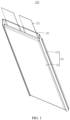
FIG. 1 is a schematic structural diagram of a secondary battery according to an embodiment of this application; -
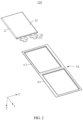
FIG. 2 is a schematic exploded view of the secondary battery inFIG. 1 ; -
FIG. 3 is a schematic diagram of an electrode plate and an electrode terminal according to an embodiment of this application; -
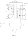
FIG. 4 is a schematic diagram of connection of an electrode terminal according to an embodiment of this application; -
FIG. 5 is a schematic diagram of connection of an electrode terminal according to another embodiment of this application; -
FIG. 6 is a schematic diagram of connection of an electrode terminal according to still another embodiment of this application; -
FIG. 7 is a cross-sectional view of connection between an electrode terminal and an electrode plate according to an embodiment of this application; -
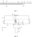
FIG. 8 is a schematic diagram of connection between an electrode terminal and an electrode plate according to another embodiment of this application; -
FIG. 9 is a cross-sectional view of connection between an electrode terminal and an electrode plate according to another embodiment of this application; -
FIG. 10 is a schematic diagram of connection of an electrode terminal according to an embodiment of this application; -
FIG. 11 is a schematic diagram of connection of an electrode terminal according to another embodiment of this application; -
FIG. 12 is a schematic structural diagram of a secondary battery with a housing omitted according to an embodiment of this application; -
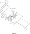
FIG. 13 is a schematic partial structural diagram of a secondary battery with a housing omitted according to an embodiment of this application; -
FIG. 14 is a partial cross-sectional view of a secondary battery according to an embodiment of this application; -
FIG. 15 is a partial cross-sectional view of a secondary battery according to another embodiment of this application; -
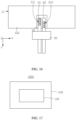
FIG. 16 is a schematic diagram of connection between an electrode terminal and an electrode plate according to still another embodiment of this application; and -
FIG. 17 is a schematic diagram of an electronic apparatus according to an embodiment of this application. - Description of reference signs of main components:
secondary battery 100 electrode assembly 10 electrode plate 11 current collector 111 first surface 1111 second surface 1112 active substance layer 112 first groove 113 tab 12 sub-tab 12a bent portion 121 connection portion 122 third surface 123 fourth surface 124 electrode terminal 20 first portion 21 first connection region 211 first edge 2111 second edge 2112 second portion 22 second connection region 221 third edge 2211 fourth edge 2212 gap 23 third portion 24 sealing member 30 housing 40 main body portion 41 sealing portion 42 first packaging portion 43 second packaging portion 44 first weld mark 50 second weld mark 60 first insulator 70 second insulator 80 apparatus body 200 electronic apparatus 1000 first direction X second direction Y third direction Z - The following describes technical solutions in some embodiments of this application with reference to the accompanying drawings in these embodiments of this application. Apparently, the described embodiments are only some rather than all of the embodiments of this application.
- It should be noted that, when one component is deemed as being "connected to" another component, it may be directly connected to the another component, or there may be a component in between. When one component is assumed as being "disposed on/in" another component, the component may be provided directly on/in the another component or with a component possibly present therebetween.
- Unless otherwise specified, the term "a plurality of" used herein refers to two or more than two.
- The terms "first", "second", and the like are merely used to distinguish between different objects, and shall not be understood as any indication or implication of relative importance or any implicit indication of the number, specific sequence, or primary-secondary relationship of the technical features indicated.
- The term "perpendicular" is used to describe an ideal state between two parts. During actual production or use, two components may be approximately perpendicular or equal to each other. For example, with reference to the description of numerical values, "perpendicular" may indicate that an included angle between two straight lines is within a range of 90°±10°, "perpendicular" may alternatively indicate that a dihedral angle of two planes is within a range of 90°±10°, and "perpendicular" may further indicate that an included angle between a straight line and a plane is within a range of 90°±10°.
- It should be noted that when a parameter is greater than, equal to, or less than an endpoint value, it should be understood that the endpoint value is allowed to have a tolerance of ±2%.
- It should be learned that sizes of layers, regions, films, plates, blocks, columns, protrusions, and depressions shown in the accompanying drawings are provided for a better understanding and a more convenient description, but this application is not limited to the sizes shown in the accompanying drawings. To make this application clear, elements irrelevant to the description are omitted from the details of the specification.
- Unless otherwise defined, all technical and scientific terms used herein shall have the same meanings as commonly understood by persons skilled in the art to which this application belongs. The terms used herein in the specification of this application are intended to merely describe specific embodiments rather than to limit this application.
- This application provides a secondary battery. The secondary battery includes an electrode assembly, an electrode terminal, and a sealing member. The electrode terminal includes a first portion and a second portion. The first portion and the second portion are arranged in a first direction. The first portion is connected to the electrode assembly and has a first connection region, and the second portion is connected to the electrode assembly and has a second connection region. The sealing member is connected to the electrode terminal, where the sealing member is disposed on one side of the electrode assembly in a second direction, and the first direction is perpendicular to the second direction. In an extension direction of the electrode terminal, the first connection region has a first edge away from the sealing member and a second edge close to the sealing member; the second connection region has a third edge away from the sealing member and a fourth edge close to the sealing member; and in the extension direction of the electrode terminal, a minimum distance between the first edge and the third edge is D1, a minimum distance between the second edge and the fourth edge is D2, and at least one of D1 or D2 is greater than 0.
- The electrode terminal includes the first portion and the second portion that are both connected to the electrode assembly, and the edges of the first connection region and the second connection region are staggered, such that tension regions between the electrode terminal and the electrode assembly are separated, reducing the risk of simultaneous disconnection of the first connection region and the second connection region, and increasing the possibility of maintained connection between the electrode terminal and the electrode assembly when the secondary battery experiences situations such as impact and bending of the electrode terminal, thereby reducing the influence of the above situations on charging, discharging, lithium precipitation, and the like on the secondary battery, and improving the reliability of the secondary battery.
- The following describes some embodiments of this application with reference to the accompanying drawings. Without conflicts, the following embodiments and features in these embodiments may be combined.
- Referring to
FIG. 1 andFIG. 2 , an embodiment of this application provides asecondary battery 100. Thesecondary battery 100 includes anelectrode assembly 10, anelectrode terminal 20, and a sealingmember 30. Theelectrode terminal 20 is connected to theelectrode assembly 10 and is configured to lead out polarity of theelectrode terminal 20 to an external circuit. The sealingmember 30 is connected to theelectrode terminal 20 and is configured to seal theelectrode assembly 10 and a part of theelectrode terminal 20 inside a packaging bag in cooperation with the packaging bag while theelectrode assembly 10 is packaged. - In some embodiments, the
secondary battery 100 is a lithium-ion battery. - In some embodiments, the
electrode assembly 10 includes a plurality ofelectrode plates 11 and a separator (not shown in the figure). Theelectrode plates 11 include a positive electrode plate and a negative electrode plate, and a separator is disposed between the positive electrode plate and the negative electrode plate. - In some embodiments, the positive electrode plate, the separator, and the negative electrode plate are stacked to form a stacked structure; and in some other embodiments, the positive electrode plate, the separator, and the negative electrode plate are stacked and then wound to form a wound structure.
- In some embodiments, referring to
FIG. 3 , theelectrode plate 11 includes acurrent collector 111 and anactive substance layer 112 disposed on thecurrent collector 111. - In some embodiments, the positive electrode plate includes a positive electrode current collector and a positive electrode active substance layer disposed on the positive electrode current collector; and the negative electrode plate includes a negative electrode current collector and a negative electrode active substance layer disposed on the negative electrode current collector.
- In some embodiments, the positive electrode active substance layer may be directly disposed on a surface of the positive electrode current collector, or a transition layer may be disposed between the positive electrode active substance layer and the positive electrode current collector; and the negative electrode active substance layer may be directly disposed on a surface of the negative electrode current collector, or a transition layer may be disposed between the negative electrode active substance layer and the negative electrode current collector.
- In some embodiments, the
current collector 111 is a metal layer. As an illustrative example, the positive electrode current collector may be a metal layer including at least one of aluminum, nickel, tantalum, or titanium, for example, an aluminum foil. The negative electrode current collector may be a metal layer including at least one of copper, nickel, tantalum, or titanium, for example, a copper foil. - In other embodiments, the
current collector 111 may be a compositecurrent collector 111 formed by a metal layer and another material layer. - In some embodiments, the positive electrode active substance layer includes a positive electrode active material, where the positive electrode active material may include at least one of lithium cobalt oxide, lithium nickel cobalt manganese oxide, lithium nickel cobalt aluminum oxide, lithium iron phosphate, lithium manganese iron phosphate, or lithium manganese oxide. The negative electrode active substance layer includes a negative electrode active material, where the negative electrode active material may include at least one of graphite, hard carbon, soft carbon, silicon, silicon-oxygen material, or silicon-carbon material.
- Referring to
FIG. 3 , theelectrode terminal 20 includes afirst portion 21 and asecond portion 22, where thefirst portion 21 and thesecond portion 22 are arranged in a first direction X, thefirst portion 21 is connected to theelectrode assembly 10 and has afirst connection region 211, and thesecond portion 22 is connected to theelectrode assembly 10 and has asecond connection region 221. - The
first connection region 211 is a region part where thefirst portion 21 is fixed to theelectrode assembly 10, and thesecond connection region 221 is a region part where thesecond portion 22 is fixed to theelectrode assembly 10. - In some embodiments, the
first portion 21 is welded to theelectrode assembly 10, and a welded region formed between thefirst portion 21 and theelectrode assembly 10 overlaps with thefirst connection region 211. Thesecond portion 22 is welded to theelectrode assembly 10, and a welded region formed between thesecond portion 22 and theelectrode assembly 10 overlaps with thesecond connection region 221. - In some embodiments, the
electrode terminal 20 is connected to thepositive electrode plate 11 or thenegative electrode plate 11. When thefirst portion 21 and thesecond portion 22 of theelectrode terminal 20 are connected to thepositive electrode plate 11, theelectrode terminal 20 has a positive polarity. When theelectrode terminal 20 is connected to thenegative electrode plate 11, theelectrode terminal 20 has a negative polarity. - In some embodiments, the
electrode terminal 20 is a metal sheet, and theelectrode terminal 20 is made of any one of copper, aluminum, or nickel. - In some embodiments, referring to
FIG. 1 andFIG. 2 , thesecondary battery 100 further includes ahousing 40, where theelectrode assembly 10 is accommodated in thehousing 40, and a part of theelectrode terminal 20 extends out of thehousing 40 and leads the polarity of theelectrode assembly 10 out of thehousing 40. - In some embodiments, referring to
FIG. 1 andFIG. 2 , thesecondary battery 100 is a pouch battery. Thehousing 40 includes amain body portion 41 and a sealingportion 42. Themain body portion 41 is provided with an electrolyte solution inside, and theelectrode assembly 10 is accommodated in themain body portion 41. The sealingportion 42 seals themain body portion 41, and theelectrode terminal 20 extends out of thehousing 40 through the sealingportion 42.FIG. 2 is a schematic exploded view of thesecondary battery 100 inFIG. 1 . To make the accompanying drawings clear, the electrolyte solution is omitted inFIG. 2 . - In some embodiments, referring to
FIG. 1 andFIG. 2 , thehousing 40 includes afirst packaging portion 43 and asecond packaging portion 44. One side of thefirst packaging portion 43 is connected to one side of thesecond packaging portion 44. A joint of thefirst packaging portion 43 and thesecond packaging portion 44 is folded, such that thefirst packaging portion 43 and thesecond packaging portion 44 are connected, and thefirst packaging portion 43 and thesecond packaging portion 44 enclose themain body portion 41. A part where thefirst packaging portion 43 and thesecond packaging portion 44 are connected forms the sealingportion 42. - In some embodiments, the
housing 40 is made of an aluminum-plastic film, and thehousing 40 serves as a packaging bag for packaging theelectrode assembly 10. - Referring to
FIG. 2 andFIG. 3 , the sealingmember 30 is connected to theelectrode terminal 20, the sealingmember 30 is disposed on one side of theelectrode assembly 10 in a second direction Y, and the first direction X is perpendicular to the second direction Y - In some embodiments, referring to
FIG. 2 andFIG. 3 , at least a part of the sealingmember 30 is disposed in the sealingportion 42, helping to improve the sealing performance for theelectrode assembly 10. - In some embodiments, the sealing
member 30 is made of plastic or rubber. - Referring to
FIG. 3 to FIG. 6 , in an extension direction of theelectrode terminal 20, thefirst connection region 211 has afirst edge 2111 away from the sealingmember 30 and asecond edge 2112 close to the sealingmember 30, and thesecond connection region 221 has athird edge 2211 away from the sealingmember 30 and afourth edge 2212 close to the sealingmember 30. In the extension direction of theelectrode terminal 20, a minimum distance between thefirst edge 2111 and thethird edge 2211 is D1, a minimum distance between thesecond edge 2112 and thefourth edge 2212 is D2, and at least one of D1 or D2 is greater than 0. - The
secondary battery 100 faces various challenges during production, transportation, or use, for example, impacts caused by a plurality of rounds of drop of thesecondary battery 100 or bending of theelectrode terminal 20. When thesecondary battery 100 is subject to an impact, there is a risk of breakage or disconnection of the connection region between theelectrode terminal 20 and theelectrode assembly 10. In the related art, considering an increase in the energy density and charge/discharge speed, thecurrent collector 111 is becoming thinner, and theelectrode terminal 20 is becoming thicker. A reacting force generated during bending of theelectrode terminal 20 is likely to cause breakage of the connection region between theelectrode terminal 20 and theelectrode assembly 10. After the connection region between theelectrode terminal 20 and theelectrode assembly 10 is broken or disconnected, continuing to charge and discharge the secondary battery causes a reliability issue such as lithium precipitation. - In this application, the
first portion 21 and thesecond portion 22 are provided, and the edges of thefirst connection region 211 and thesecond connection region 221 are staggered, such that the tension regions between theelectrode terminal 20 and theelectrode assembly 10 are separated, reducing the risk of simultaneous disconnection of thefirst connection region 211 and thesecond connection region 221, and increasing the possibility of maintained connection between theelectrode terminal 20 and theelectrode assembly 10 when thesecondary battery 100 faces situations such as impact and bending of theelectrode terminal 20, thereby reducing the influence of the above situations on charging, discharging, lithium precipitation, and the like on thesecondary battery 100, and improving the reliability of thesecondary battery 100. - In some embodiments, referring to
FIG. 5 andFIG. 6 , D1>0 and D2=0; and in some other embodiments, D1=0 and D2>0. - In some embodiments, referring to
FIG. 4 , D1>0 and D2>0, such that thefirst edge 2111 and thethird edge 2211 are staggered, and thesecond edge 2112 and thefourth edge 2212 are staggered, achieving a more significant separation effect on the tension regions between theelectrode terminal 20 and theelectrode assembly 10, thereby helping to further improve the reliability of thesecondary battery 100. - In some embodiments, the
first edge 2111, thesecond edge 2112, thethird edge 2211, and thefourth edge 2212 may be straight edges extending along the first direction X. Alternatively, thefirst edge 2111, thesecond edge 2112, thethird edge 2211, and thefourth edge 2212 may be curved, zigzag, or wavy edges. This is not specifically limited herein. - In some embodiments, referring to
FIG. 4 , Di>0, and in the extension direction of theelectrode terminal 20, a length of thefirst connection region 211 is L1, and a length of thesecond connection region 221 is L2, and L1>D1 and L2>D1. - In some embodiments, referring to
FIG. 4 , D2>0, and in the extension direction of theelectrode terminal 20, a length of thefirst connection region 211 is L1, and a length of thesecond connection region 221 is L2, and L1>D2 and L2>D2. - When L1>D1>0 and L2>D1>0 or L1>D2>0 and L2>D2>0 are satisfied, a distance by which the
first connection region 211 and thesecond connection region 221 are staggered in the extension direction of theelectrode terminal 20 is not greater than the length of any one of the connection regions, such that thefirst connection region 211 and thesecond connection region 221 are not entirely staggered, helping to reduce a length occupied by both the two connection regions. When a region, which may be connected to theelectrode terminal 20, on theelectrode assembly 10 is fixed, the above conditions being satisfied helps to increase the lengths of thefirst connection region 211 and thesecond connection region 221 so as to improve the stability of the connection between theelectrode terminal 20 and theelectrode assembly 10, thereby improving the reliability of thesecondary battery 100. - In some embodiments, 0.5 mm ≤L1≤30 mm being satisfied helps to increase a connection area between the
first portion 21 and theelectrode assembly 10, thereby reducing the risk of short circuit of thesecondary battery 100 caused by separation of theelectrode terminal 20 and theelectrode assembly 10. - In an illustrative example, L1 may be any one of 0.5 mm, 1 mm, 2 mm, 4 mm, 6 mm, 8 mm, 10 mm, 12 mm, 14 mm, 16 mm, 18 mm, 20 mm, 22 mm, 24 mm, 26 mm, 28 mm, or 30 mm.
- In some embodiments, 0.5 mm ≤L2≤30 mm being satisfied helps to increase a connection area between the
first portion 21 and theelectrode assembly 10, thereby reducing the risk of short circuit of thesecondary battery 100 caused by separation of theelectrode terminal 20 and theelectrode assembly 10. - In an illustrative example, L2 may be any one of 0.5 mm, 1 mm, 2 mm, 4 mm, 6 mm, 8 mm, 10 mm, 12 mm, 14 mm, 16 mm, 18 mm, 20 mm, 22 mm, 24 mm, 26 mm, 28 mm, or 30 mm.
- In some embodiments, the
first portion 21 is welded to theelectrode assembly 10, and thefirst connection region 211 is a welded region. - In some embodiments, the
second portion 22 is welded to theelectrode assembly 10, and thesecond connection region 221 is a welded region. - In some embodiments, referring to
FIG. 4 , agap 23 is provided between thefirst portion 21 and thesecond portion 22 in the first direction X. Thegap 23 separates thefirst portion 21 and thesecond portion 22, reducing the mutual influence between thefirst portion 21 and thesecond portion 22. - For example, the
gap 23 provided between thefirst portion 21 and thesecond portion 22 helps to reduce the risk of thefirst portion 21 and thesecond portion 22 being welded together during welding of thefirst portion 21 and theelectrode assembly 10, or helps to reduce the risk of thefirst portion 21 and thesecond portion 22 being welded together during welding of thesecond portion 22 and theelectrode assembly 10. - For another example, the
gap 23 provided between thefirst portion 21 and thesecond portion 22 helps to reduce the risk of thefirst portion 21 coming into contact with thesecond portion 22 and transmitting a force to thesecond portion 22 during stress deformation, or helps to reduce the risk of thesecond portion 22 coming into contact with thefirst portion 21 and transmitting a force to thefirst portion 21 during stress deformation. - In some embodiments, referring to
FIG. 2 .FIG. 3 , andFIG. 7 , theelectrode assembly 10 includes anelectrode plate 11. Theelectrode plate 11 includes acurrent collector 111. Thecurrent collector 111 has afirst surface 1111 and asecond surface 1112 opposite to each other. Thefirst portion 21 is connected to thefirst surface 1111 to form thefirst connection region 211, and thesecond portion 22 is connected to thefirst surface 1111 to form thesecond connection region 221. - The
first portion 21 and thesecond portion 22 are both connected to thefirst surface 1111, such that thefirst portion 21 and thesecond portion 22 are connected to a same side surface of thecurrent collector 111, reducing a procedure of turning over thesecondary battery 100 during connection, reducing the difficulty in connection, and improving the connection efficiency. - In some embodiments, referring to
FIG. 2 ,FIG. 8 , andFIG. 9 , theelectrode assembly 10 includes anelectrode plate 11. Theelectrode plate 11 includes acurrent collector 111. Thecurrent collector 111 has afirst surface 1111 and asecond surface 1112 opposite to each other. Thefirst portion 21 is connected to thefirst surface 1111 to form thefirst connection region 211, and thesecond portion 22 is connected to thesecond surface 1112 to form thesecond connection region 221. - The
first portion 21 is connected to thefirst surface 1111, and thesecond portion 22 is connected to thesecond surface 1112, such that thefirst portion 21 and thesecond portion 22 are connected to different sides of theelectrode plate 11, helping to reduce the mutual influence between thefirst portion 21 and thesecond portion 22. For example, thefirst portion 21 and thesecond portion 22 being connected to different sides of theelectrode plate 11 helps to reduce the risk of thefirst portion 21 and thesecond portion 22 being welded together, and also helps to reduce the risk of mutual force transmission between thefirst portion 21 and thesecond portion 22. In addition, thefirst portion 21 and thesecond portion 22 being connected to different sides of theelectrode plate 11 also helps to disperse the tension regions between theelectrode terminal 20 and theelectrode assembly 10. - In an embodiment in which the
electrode terminal 20 is connected to theelectrode plate 11, referring toFIG. 2 ,FIG. 3 , andFIG. 8 , theelectrode assembly 10 includes anelectrode plate 11. Theelectrode plate 11 includes acurrent collector 111 and anactive substance layer 112, where theactive substance layer 112 is disposed on thecurrent collector 111. Theactive substance layer 112 is provided with afirst groove 113, and thefirst groove 113 exposes thecurrent collector 111. At least a part of thefirst portion 21 and a part of thesecond portion 22 are located in thefirst groove 113, and thefirst portion 21 and thesecond portion 22 are connected to thecurrent collector 111 exposed from thefirst groove 113. In the second direction Y, a width of thefirst groove 113 is T1. - In some embodiments, the
active substance layer 112 is further provided with a second groove (not shown in the figure). One of theelectrode terminal 20 of the positive electrode or theelectrode terminal 20 of the negative electrode is located in thefirst groove 113, and theelectrode terminal 20 of the other electrode is located in the second groove. - In some embodiments, a part of the
active substance layer 112 on thecurrent collector 111 is washed off to expose a part of thecurrent collector 111, so as to form thefirst groove 113 and the second groove. At least a part of thefirst portion 21 and at least a part of thesecond portion 22 are located in thefirst groove 113 and connected to thecurrent collector 111. - In an embodiment in which the
electrode terminal 20 is connected to theelectrode plate 11, referring toFIG. 3 andFIG. 8 , a length of an orthographic projection of thefirst portion 21 on theelectrode plate 11 in the second direction Y is T2, and a length of an orthographic projection of thesecond portion 22 on theelectrode plate 11 in the second direction Y is T3, and T1-0.5 mm≥T2≥T1-5 mm and T1-0.5 mm≥T3≥T1-5 mm. This helps to reduce the risk of thefirst portion 21 and thesecond portion 22 coming into contact with theactive substance layer 112 when thesecondary battery 100 is subject to an impact. - In an embodiment in which the
electrode terminal 20 is connected to theelectrode plate 11, referring toFIG. 4 , a minimum width of thegap 23 in the first direction X is W1, and 3 mm≥W1≥0.5 mm. - It should be noted that the minimum width W1 of the
gap 23 is a minimum distance between an edge of thefirst portion 21 close to thesecond portion 22 and an edge of thesecond portion 22 close to thefirst portion 21 in the first direction X. - The minimum width W1 of the
gap 23 satisfying 3 mm≥W1≥0.5 mm helps to further increase the widths of thefirst portion 21 and thesecond portion 22 in the first direction X within a limited space, can enhance the structural strength of thefirst portion 21 and thesecond portion 22, also helps to increase areas of thefirst connection region 211 and thesecond connection region 221, and reduces the risk of breakage of thefirst connection region 211 and thesecond connection region 221, thereby improving the reliability of thesecondary battery 100. - In an illustrative example, W1 may be any one of 3 mm, 2.8 mm, 2.5 mm, 2.2 mm, 2 mm, 1.8 mm, 1.5 mm, 1.3 mm, 1 mm, 0.8 mm, or 0.5 mm.
- In an embodiment in which the
electrode terminal 20 is connected to theelectrode plate 11, referring toFIG. 10 , theelectrode plate 11 of theelectrode assembly 10 is welded to thefirst portion 21, a plurality of first weld marks 50 are provided between theelectrode plate 11 of theelectrode assembly 10 and thefirst portion 21, and the plurality of first weld marks 50 are located in thefirst connection region 211. In the first direction X, a width of thefirst weld mark 50 is S1, and 0.5 mm≤S1≤8 mm. - In some embodiments, referring to
FIG. 11 , theelectrode plate 11 of theelectrode assembly 10 and thefirst portion 21 are welded row by row, and the plurality of first weld marks 50 are sequentially connected to form a continuous weld mark. - In some embodiments, referring to
FIG. 10 , theelectrode plate 11 of theelectrode assembly 10 and thefirst portion 21 are not welded row by row, and the plurality of first weld marks 50 are spaced apart in the extension direction of theelectrode terminal 20. In the extension direction of theelectrode terminal 20, a length of thefirst weld mark 50 is S2, and 0.5 mm≤S2≤8 mm. - When the length and width of the
first weld mark 50 satisfy the above conditions, the welded region is not too small, helping to enhance the welding strength and helping to improve the stability of the connection between theelectrode terminal 20 and theelectrode assembly 10; moreover, the welded region is not too large, helping to reduce the risk of a failure in effective welding and reduce the risk of structural strength reduction of theelectrode terminal 20, thereby improving the welding effect. - In an embodiment in which the
electrode terminal 20 is connected to theelectrode plate 11, referring toFIG. 10 , theelectrode plate 11 of theelectrode assembly 10 is welded to thesecond portion 22, a plurality of second weld marks 60 are provided between theelectrode plate 11 of theelectrode assembly 10 and thesecond portion 22, and the plurality of second weld marks 60 are located in thesecond connection region 221. For a width of thesecond weld mark 60 in the first direction X and a length of thesecond weld mark 60 in the extension direction of theelectrode terminal 20, reference may be made to thefirst weld mark 50, which is not described herein again. - In an illustrative example, S1 and S2 each may be any one of 8 mm, 7.5 mm, 7 mm, 6.5 mm, 6 mm, 5.5 mm, 5 mm, 4.5 mm, 4 mm, 3.5 mm, 3 mm, 2.8 mm, 2.5 mm, 2.2 mm, 2 mm, 1.8 mm, 1.5 mm, 1.3 mm, 1 mm, 0.8 mm, or 0.5 mm. S1 and S2 may be equal or not equal.
- In some embodiments, referring to
FIG. 12 to FIG. 14 , theelectrode assembly 10 is a stacked structure. Theelectrode assembly 10 includes a plurality of stackedelectrode plates 11. Theelectrode plate 11 includes acurrent collector 111, a sub-tab 12a, and anactive substance layer 112. The sub-tab 12a is connected to thecurrent collector 111, and theactive substance layer 112 is disposed on thecurrent collector 111. A plurality of sub-tabs 12a are stacked and connected to form atab 12. Thetab 12 has athird surface 123 and afourth surface 124 opposite to each other. Thefirst portion 21 is connected to thethird surface 123 to form thefirst connection region 211, and thesecond portion 22 is connected to thethird surface 123 to form thesecond connection region 221. - The
first portion 21 and thesecond portion 22 are both connected to thethird surface 123, such that thefirst portion 21 and thesecond portion 22 are connected to a same side surface of thetab 12, reducing a procedure of turning over thesecondary battery 100 during connection, reducing the difficulty in connection, and improving the connection efficiency. - In some embodiments, referring to
FIG. 15 , theelectrode assembly 10 includes a plurality of stackedelectrode plates 11. Theelectrode plate 11 includes acurrent collector 111, a sub-tab 12a, and anactive substance layer 112. The sub-tab 12a is connected to thecurrent collector 111, and theactive substance layer 112 is disposed on thecurrent collector 111. A plurality of sub-tabs 12a are stacked and connected to form atab 12. Thetab 12 has athird surface 123 and afourth surface 124 opposite to each other. Thefirst portion 21 is connected to thethird surface 123 to form thefirst connection region 211, and thesecond portion 22 is connected to thefourth surface 124 to form thesecond connection region 221. - The
first portion 21 is connected to thethird surface 123, and thesecond portion 22 is connected to thefourth surface 124, such that thefirst portion 21 and thesecond portion 22 are connected to different sides of thetab 12, helping to reduce the mutual influence between thefirst portion 21 and thesecond portion 22. For example, thefirst portion 21 and thesecond portion 22 being connected to different sides of thetab 12 helps to reduce the risk of thefirst portion 21 and thesecond portion 22 being welded together, and also helps to reduce the risk of mutual force transmission between thefirst portion 21 and thesecond portion 22. In addition, thefirst portion 21 and thesecond portion 22 being connected to different sides of thetab 12 also helps to disperse the tension regions between theelectrode terminal 20 and theelectrode assembly 10. - In an embodiment in which the
electrode terminal 20 is connected to thetab 12, the sub-tab 12a is formed by cutting thecurrent collector 111, and the sub-tab 12a and thecurrent collector 111 are made of a same material. - In an embodiment in which the
electrode terminal 20 is connected to thetab 12, referring toFIG. 4 , a minimum width of thegap 23 in the first direction X is W1, and 5 mm≥W1>0.5 mm. - It should be noted that the minimum width W1 of the
gap 23 is a minimum distance between an edge of thefirst portion 21 close to thesecond portion 22 and an edge of thesecond portion 22 close to thefirst portion 21 in the first direction X. - The minimum width W1 of the
gap 23 satisfying 5 mm≥W1≥0.5 mm helps to reduce the mutual influence between thefirst portion 21 and thesecond portion 22, also helps to increase the widths of thefirst portion 21 and thesecond portion 22 in the first direction X within a limited space, can enhance the structural strength of thefirst portion 21 and thesecond portion 22, also helps to increase the areas of thefirst connection region 211 and thesecond connection region 221, and reduces the risk of breakage of thefirst connection region 211 and thesecond connection region 221, thereby improving the reliability of thesecondary battery 100. - In an illustrative example, W1 may be any one of 5 mm, 4.8 mm, 4.5 mm, 4.2 mm, 4 mm, 3.8 mm, 3.5 mm, 3.2 mm, 3 mm, 2.8 mm, 2.5 mm, 2.2 mm, 2 mm, 1.8 mm, 1.5 mm, 1.3 mm, 1 mm, 0.8 mm, or 0.5 mm.
- In an embodiment in which the
electrode terminal 20 is connected to thetab 12, referring toFIG. 14 and FIG. 15 , a plurality of sub-tabs 12a are stacked and then bent along a third direction Z (a thickness direction of the secondary battery 100), to make thetab 12 have abent portion 121 and aconnection portion 122. In an extension direction of thetab 12, theconnection portion 122 is located on one side of thebent portion 121 away from theelectrode assembly 10. Theconnection portion 122 extends along the third direction Z, and thefirst portion 21 and the second portion are both connected to theconnection portion 122. - In some embodiments, referring to
FIG. 14 and FIG. 15 , a minimum distance between thefirst portion 21 and a boundary line of thebent portion 121 and theconnection portion 122 is P1, and a minimum distance between thesecond portion 22 and a boundary line of thebent portion 121 and theconnection portion 122 is P2, and 0.5 mm>P1>5 mm and 0.5 mm>P2>5 mm. This helps to reduce the possibility of contact between end portions of thefirst portion 21 andsecond portion 22 and thebent portion 121 during bending of the plurality of sub-tabs 12a, thereby reducing a reacting force applied to thefirst portion 21 and thesecond portion 22, reducing the risk of breakage of thefirst connection region 211 and thesecond connection region 221, and improving the reliability of thesecondary battery 100. - In an illustrative example, P1 and P2 each may be any one of 5 mm, 4.8 mm, 4.5 mm, 4.2 mm, 4 mm, 3.8 mm, 3.5 mm, 3.2 mm, 3 mm, 2.8 mm, 2.5 mm, 2.2 mm, 2 mm, 1.8 mm, 1.5 mm, 1.3 mm, 1 mm, 0.8 mm, or 0.5 mm. P1 and P2 may be equal or not equal.
- In an embodiment in which the
electrode terminal 20 is connected to thetab 12, thetab 12 of theelectrode assembly 10 is welded to thefirst portion 21, a plurality of first weld marks 50 are provided between thetab 12 of theelectrode assembly 10 and thefirst portion 21, and the plurality of first weld marks 50 are located in thefirst connection region 211. In the first direction X, a width of thefirst weld mark 50 is S1, and 0.5 mm≤S1≤3 mm. In the extension direction of theelectrode terminal 20, a length of thefirst weld mark 50 is S2, and 0.5 mm≤S2≤3 mm. - When the length and width of the
first weld mark 50 satisfy the above conditions, the welded region is not too small, helping to enhance the welding strength and helping to improve the stability of the connection between theelectrode terminal 20 and theelectrode assembly 10; moreover, the welded region is not too large, helping to reduce the risk of a failure in effective welding and reduce the risk of structural strength reduction of theelectrode terminal 20, thereby improving the welding effect. - In an embodiment in which the
electrode terminal 20 is connected to thetab 12, thetab 12 of theelectrode assembly 10 is welded to thesecond portion 22, a plurality of second weld marks 60 are provided between thetab 12 of theelectrode assembly 10 and thesecond portion 22, and the plurality of second weld marks 60 are located in thesecond connection region 221. For a width of thesecond weld mark 60 in the first direction X and a length of thesecond weld mark 60 in the extension direction of theelectrode terminal 20, reference may be made to thefirst weld mark 50, which is not described herein again. - In some embodiments, referring to
FIG. 13 , the plurality of first weld marks 50 are arranged along the extension direction of theelectrode terminal 20, and the plurality of second weld marks 60 are arranged along the extension direction of theelectrode terminal 20. In the extension direction of theelectrode terminal 20, a distance between any two adjacent first weld marks 50 is D3, and a distance between any two adjacent second weld marks 60 is D4, and 0.5 mm≤D3≤3 mm and 0.5 mm≤D4≤3 mm. - When the distance D3 between any two adjacent first weld marks 50 and the distance D4 between any two adjacent second weld marks 60 satisfy the above conditions, the plurality of first weld marks 50 are unlikely to be too far apart and the plurality of second weld marks 60 are unlikely to be too far apart such that the first weld marks 50 and the second weld marks 60 are unlikely to crack, thereby improving the stability of the connection between the
electrode terminal 20 and theelectrode assembly 10; in addition, the first weld marks 50 are unlikely to be too close to each other such that the difficulty in effective welding is avoided, thereby improving the welding effect. - In an illustrative example, D3 and D4 may be any one of 3 mm, 2.8 mm, 2.5 mm, 2.2 mm, 2 mm, 1.8 mm, 1.5 mm, 1.3 mm, 1 mm, 0.8 mm, or 0.5 mm. W3 and W4 may be equal or not equal.
- In some embodiments, referring to
FIG. 13 , in the extension direction of theelectrode terminal 20, a distance between thesecond edge 2112 and the sealingmember 30 is less than or equal to a distance between thethird edge 2211 and the sealingmember 30. In the extension direction of theelectrode terminal 20, a minimum distance between a geometric center of afirst weld mark 50 closest to thesecond edge 2112 among the plurality of first weld marks 50 and a geometric center of asecond weld mark 60 closest to thethird edge 2211 among the plurality of second weld marks 60 is D5, and 0.5 mm<Ds<3 mm. - D5 satisfying the condition 0.5 mm<Ds<3 mm helps to reduce the risk of the structural strength of the
electrode terminal 20 being affected by an excessively large welded region and also helps to reduce the risk of unstable connection caused by an excessively small welded region. - In an illustrative example, D5 may be any one of 3 mm, 2.8 mm, 2.5 mm, 2.2 mm, 2 mm, 1.8 mm, 1.5 mm, 1.3 mm, 1 mm, 0.8 mm, or 0.5 mm.
- To verify the impact of various dimensions of the
electrode terminal 20 on the performance of thesecondary battery 100, the following test was performed. - A method for testing a failure rate of a drop test of the
secondary battery 100 was as follows. - The
secondary battery 100 was pretreated at 25°C and left for standing in a normal-temperature environment for 60 min, and then a voltage of thesecondary battery 100 was tested before the drop test; thesecondary battery 100 was put into a fixture; and a drop device was used to freely drop thesecondary battery 100 from a position that is 2 m high from the ground according to the following sequence: head-tail-head right corner-tail right corner-head left corner-tail left corner (angle: 45±15°), and such operation was repeated for 10 rounds. After the drop test, a voltage of thesecondary battery 100 was measured and recorded, where appearances of thesecondary battery 100 before and after the test were both inspected and photographed. Criteria for pass of the drop test were: no smoke, no electrolyte solution leakage, and a voltage drop < 30 mV. - The following describes specific implementations of the examples and comparative examples. 20
secondary batteries 100 were used for test in each group of examples and comparative examples uses. -
- (1) Preparation of negative electrode plate: Graphite was used as a negative electrode active material; the negative electrode active material graphite, a binder styrene butadiene rubber (SBR), and a thickener sodium carboxymethyl cellulose (CMC) were mixed at a weight ratio of 96:2:2; deionized water was added as a solvent to prepare a slurry with a solid content of 70wt%; and the slurry was well stirred. The slurry was uniformly applied onto one surface of a 10 µm thick copper foil and dried to obtain a negative electrode plate with one surface coated with a negative electrode active layer. The foregoing steps were repeated on the other surface of the copper foil to obtain a negative electrode plate with both surfaces coated with the negative electrode active layer.
- (2) Preparation of positive electrode plate: a positive electrode active material lithium cobalt oxide (LiCoO2), conductive carbon black (Super P), and polyvinylidene fluoride (PVDF) were mixed at a weight ratio of 97.5:1.0:1.5; then N-methylpyrrolidone (NMP) was added as a solvent to obtain a slurry with a solid content of 75wt%; and the slurry was well stirred. The slurry was uniformly applied onto one surface of a 12 µm thick aluminum foil and dried to obtain a positive electrode plate with one surface coated with a positive electrode active layer. The foregoing steps were repeated on the other surface of the aluminum foil to obtain a positive electrode plate with both surfaces coated with the positive electrode active layer.
- (3) Preparation of electrolyte: In a dry argon atmosphere, first, ethylene carbonate (EC), ethyl methyl carbonate (EMC), and diethyl carbonate (DEC) were mixed at a mass ratio of EC: EMC: DEC=30:50:20 to form a base organic solvent; then a lithium salt lithium hexafluorophosphate (LiPF6) was added and dissolved in the base organic solvent; and the resulting mixture was well mixed to obtain an electrolyte solution in which a mass concentration of LiPF6 was 12.5%.
- (4) Preparation of separator: A polyethylene porous film was used as a substrate layer; one side surface of the substrate layer was coated with a ceramic layer containing aluminum oxide ceramics and a PVDF binder, where a mass percentage of the aluminum oxide ceramics in the ceramic layer was 95%.
- (5) Preparation of electrode assembly 10: A copper foil of the negative electrode plate (negative electrode current collector) was cut into a protruding narrow copper foil (negative electrode sub-tab), and an aluminum foil of the positive electrode plate (positive electrode current collector) was cut into a protruding narrow aluminum foil (positive electrode sub-tab). A plurality of layers of positive electrode plates, separators, and negative electrode plates were stacked to form an
electrode assembly 10 for later use. A plurality of narrow copper foil layers were stacked to form a copper sheet (negative electrode tab), and a plurality of narrow aluminum foil layers were stacked to form an aluminum sheet (positive electrode tab). - (6) Connection of electrode terminal 20: One copper sheet was provided with a sealing adhesive (sealing member 30) to form a negative electrode terminal; one aluminum sheet was provided with a sealing adhesive (sealing member 30) to form a positive electrode terminal; and the negative electrode terminal and the positive electrode terminal were both cut in a length direction to form two portions arranged in a width direction. A
first portion 21 and asecond portion 22 of the negative electrode terminal were both welded to an upper surface of the negative electrode tab, and afirst portion 21 and asecond portion 22 of the positive electrode terminal were both welded to an upper surface of the positive electrode tab. - The electrode terminals and the tabs were each welded to form a
first connection region 211 and asecond connection region 221, where thefirst connection region 211 had afirst edge 2111 away from the sealingmember 30 and asecond edge 2112 close to the sealingmember 30, and thesecond connection region 221 had athird edge 2211 away from the sealingmember 30 and afourth edge 2212 close to the sealingmember 30. In an extension direction of theelectrode terminal 20, a minimum distance Di between thefirst edge 2111 and thethird edge 2211 was 2 mm, and a minimum distance D2 between thesecond edge 2112 and thefourth edge 2212 was 0 mm. - In an arrangement direction of the
first portion 21 and thesecond portion 22, agap 23 was provided between thefirst portion 21 and thesecond portion 22, and a minimum width W1 of thegap 23 was 1 mm. - In the extension direction of the
electrode terminal 20, a length L1 of thefirst connection region 211 was 3 mm, and a length L2 of thesecond connection region 221 was 2.5 mm. - A plurality of first weld marks 50 were provided between an
electrode plate 11 of theelectrode assembly 10 and thefirst portion 21, and a width S1 of thefirst weld mark 50 was 1 mm in an arrangement direction of thefirst portion 21 and thesecond portion 22. In the extension direction of theelectrode terminal 20, a length S2 of thefirst weld mark 50 was 1 mm. - (7) Assembly of electrode assembly 10: An aluminum-plastic film with a depression formed through punching was placed into an assembly fixture, with surface facing upward; and the
electrode assembly 10 was placed into the depression and pressed by an external forced applied. Then, another aluminum-plastic film with a depression formed through punching was used to cover theelectrode assembly 10, with surface facing downward; and peripheries of the two aluminum-plastic films were thermally sealed through hot pressing to obtain an assembled electrode assembly. - (8) electrolyte solution injection and packaging: An electrolyte solution was injected into the assembled
electrode assembly 10, followed by processes such as vacuum packaging, standing, hot-pressing formation, and shaping, to obtain a lithium-ion battery. - It should be noted that the above serial numbers (1) to (8) do not limit the sequence of the steps.
- Comparative example 1 differed from Example 1 in that the
electrode terminal 20 of thesecondary battery 100 in Comparative example 1 was not cut, the positive electrode terminal and the negative electrode terminal were each a continuous entirety, and a connection region of theelectrode terminal 20 and thetab 12 was also a continuous entirety. - Example 2 differed from Example 1 in that the minimum distance D1 between the
first edge 2111 and thethird edge 2211 was 0 mm, and the minimum distance D2 between thesecond edge 2112 and thefourth edge 2212 was 1.5 mm. - Example 3 differed from Example 1 in that the minimum distance D2 between the
second edge 2112 and thefourth edge 2212 was 1.5 mm. - Example 4 differed from Example 1 in that the minimum distance D2 between the
second edge 2112 and thefourth edge 2212 was 1.5 mm, and in the arrangement direction of thefirst portion 21 and thesecond portion 22, the minimum width W1 of thegap 23 was 0 mm. - Example 5 differed from Example 1 in that the minimum distance D2 between the
second edge 2112 and thefourth edge 2212 was 1.5 mm, and in the arrangement direction of thefirst portion 21 and thesecond portion 22, the minimum width W1 of thegap 23 was 0.5 mm. - Example 6 differed from Example 1 in that the minimum distance D2 between the
second edge 2112 and thefourth edge 2212 was 1.5 mm, and in the arrangement direction of thefirst portion 21 and thesecond portion 22, the minimum width W1 of thegap 23 was 2 mm. - Example 7 differed from Example 1 in that the minimum distance D2 between the
second edge 2112 and thefourth edge 2212 was 1.5 mm, and in the arrangement direction of thefirst portion 21 and thesecond portion 22, the minimum width W1 of thegap 23 was 3 mm. - Example 8 differed from Example 1 in that the minimum distance D2 between the
second edge 2112 and thefourth edge 2212 was 1.5 mm, and in the arrangement direction of thefirst portion 21 and thesecond portion 22, the minimum width W1 of thegap 23 was 4 mm. - Example 9 differed from Example 1 in that the minimum distance D2 between the
second edge 2112 and thefourth edge 2212 was 1.5 mm, and in the arrangement direction of thefirst portion 21 and thesecond portion 22, the minimum width W1 of thegap 23 was 5 mm. - Example 10 differed from Example 1 in that the minimum distance D2 between the
second edge 2112 and thefourth edge 2212 was 1.5 mm, and in the arrangement direction of thefirst portion 21 and thesecond portion 22, the minimum width W1 of thegap 23 was 5.5 mm. - Example 11 differed from Example 1 in that the minimum distance D2 between the
second edge 2112 and thefourth edge 2212 was 1.5 mm, the width S1 of thefirst weld mark 50 was 0.3 mm, and in the extension direction of theelectrode terminal 20, the length S2 of thefirst weld mark 50 was 0.3 mm. - Example 12 differed from Example 1 in that the minimum distance D2 between the
second edge 2112 and thefourth edge 2212 was 1.5 mm, the width S1 of thefirst weld mark 50 was 0.5 mm, and in the extension direction of theelectrode terminal 20, the length S2 of thefirst weld mark 50 was 0.5 mm. - Example 13 differed from Example 1 in that the minimum distance D2 between the
second edge 2112 and thefourth edge 2212 was 1.5 mm, the width S1 of thefirst weld mark 50 was 2 mm, and in the extension direction of theelectrode terminal 20, the length S2 of thefirst weld mark 50 was 2 mm. - Example 14 differed from Example 1 in that the minimum distance D2 between the
second edge 2112 and thefourth edge 2212 was 1.5 mm, the width S1 of thefirst weld mark 50 was 4 mm, and in the extension direction of theelectrode terminal 20, the length S2 of thefirst weld mark 50 was 4 mm. - Example 15 differed from Example 1 in that the minimum distance D2 between the
second edge 2112 and thefourth edge 2212 was 1.5 mm, the width S1 of thefirst weld mark 50 was 6 mm, and in the extension direction of theelectrode terminal 20, the length S2 of thefirst weld mark 50 was 6 mm. - Example 16 differed from Example 1 in that the minimum distance D2 between the
second edge 2112 and thefourth edge 2212 was 1.5 mm, the width S1 of thefirst weld mark 50 was 8 mm, and in the extension direction of theelectrode terminal 20, the length S2 of thefirst weld mark 50 was 8 mm. - Example 17 differed from Example 1 in that the minimum distance D2 between the
second edge 2112 and thefourth edge 2212 was 1.5 mm, the width S1 of thefirst weld mark 50 was 9 mm, and in the extension direction of theelectrode terminal 20, the length S2 of thefirst weld mark 50 was 9 mm. - Example 18 differed from Example 1 in that the minimum distance D2 between the
second edge 2112 and thefourth edge 2212 was 1.5 mm, and in the extension direction of theelectrode terminal 20, the length L1 of thefirst connection region 211 was 2 mm, and the length L2 of thesecond connection region 221 was 1.5 mm. - Example 19 differed from Example 1 in that the minimum distance D2 between the
second edge 2112 and thefourth edge 2212 was 1.5 mm, and in the arrangement direction of thefirst portion 21 and thesecond portion 22 and in the extension direction of theelectrode terminal 20, the length L1 of thefirst connection region 211 was 1 mm, and the length L2 of thesecond connection region 221 was 0.5 mm. - The following Table 1 shows the data and test results of the above test.
Table 1: Drop test results of secondary battery Group D1 (mm) D2 (mm) W1 (mm) L1 (mm) L2 (mm) S1 (mm) S2 (mm) Failure rate in drop test Comparative example 1 - - - 3 2.5 1 1 14/20 Example 1 2 0 1 3 2.5 1 1 7/20 Example 2 0 1.5 1 3 2.5 1 1 8/20 Example 3 2 1.5 1 3 2.5 1 1 0/20 Example 4 2 1.5 0 3 2.5 1 1 9/20 Example 5 2 1.5 0.5 3 2.5 1 1 3/20 Example 6 2 1.5 2 3 2.5 1 1 1/20 Example 7 2 1.5 3 3 2.5 1 1 2/20 Example 8 2 1.5 4 3 2.5 1 1 3/20 Example 9 2 1.5 5 3 2.5 1 1 4/20 Example 10 2 1.5 5.5 3 2.5 1 1 7/20 Example 11 2 1.5 1 3 2.5 0.3 0.3 6/20 Example 12 2 1.5 1 3 2.5 0.5 0.5 3/20 Example 13 2 1.5 1 3 2.5 2 2 2/20 Example 14 2 1.5 1 3 2.5 4 4 1/20 Example 15 2 1.5 1 3 2.5 6 6 3/20 Example 16 2 1.5 1 3 2.5 8 8 4/20 Example 17 2 1.5 1 3 2.5 9 9 9/20 Example 18 2 1.5 1 2 1.5 1 1 4/20 Example 19 2 1.5 1 1 0.5 1 1 5/20 - It can be seen from the above Table 1 that as compared with Comparative example 1, at least one of D1 or D2 in Examples 1 to 3 is greater than 0; when at least one of D1 or D2 is greater than 0, the
first edge 2111 and thethird edge 2211 are staggered, and/or thesecond edge 2112 and thefourth edge 2212 are staggered, such that the tension regions between theelectrode terminal 20 and theelectrode assembly 10 are separately more significantly, and a failure rate of the drop test of thesecondary battery 100 is lower. Thus, a percent of pass of the drop test is higher, helping to improve the reliability of thesecondary battery 100. - It can be seen from Table 1 that as compared with Example 4 and Example 10, in Example 3 and Examples 5 to 9, 5 mm≥W1>0.5 mm is satisfied; and 5 mm≥W1>0.5 mm being satisfied helps to reduce the risk of breakage of the first connection region and the second connection region, also helps to isolate spreading of cracks, and reduces the failure rate of the drop test of the
secondary battery 100. Thus, the percent of pass of the drop test is higher, helping to improve the reliability of thesecondary battery 100. - It can be seen from Table 1 that as compared with Example 11 and Example 17, in Example 3 and Examples 12 to 16, 0.5 mm≤S1≤8 mm and 0.5 mm≤S2≤8 mm are satisfied; and 0.5 mm≤S1≤8 mm and 0.5 mm≤S2≤8 mm being satisfied helps to enhance the welding strength, reduces the risk of a failure in effective welding, reduces the risk of structural strength reduction of the
electrode terminal 20, improves the welding effect, and reduces the failure rate of the drop test of thesecondary battery 100. Thus, the percent of pass of the drop test is higher, helping to improve the reliability of thesecondary battery 100. - It can be seen from Table 1 that as compared with Examples 1, 2, 18, and 19, in Example 3, L1>D1>0 and L2>D2>0 are satisfied; and L1>D1>0 and L2>D2>0 being satisfied helps to reduce the lengths of the
first connection region 211 and thesecond connection region 221, thereby improving the stability of connection between theelectrode terminal 20 and theelectrode assembly 10 and reducing the failure rate of the drop test of thesecondary battery 100. Thus, the percent of pass of the drop test is higher, helping to improve the reliability of thesecondary battery 100. - In some embodiments, referring to
FIG. 14 , thesecondary battery 100 further includes afirst insulator 70 and asecond insulator 80. Thefirst insulator 70 is adhered to thefirst portion 21 and/or thesecond portion 22, and is located on one side of theconnection portion 122. Thesecond insulator 80 is adhered to thetab 12 and theelectrode terminal 20, and is located on the other side of theconnection portion 122. Thefirst insulator 70 and thesecond insulator 80 reduce the risk of contact between theelectrode terminal 20 and a component with another polarity. - In some embodiments, referring to
FIG. 1 andFIG. 13 , theelectrode terminal 20 further includes athird portion 24. Thethird portion 24 connects thefirst portion 21 and thesecond portion 22. Thethird portion 24 is connected to the sealingmember 30. Thethird portion 24 is configured to be connected to an external device. Thethird portion 24 provided helps to enhance the integrity of theelectrode terminal 20 and facilitates the connection between theelectrode terminal 20 and the external device. - In an embodiment in which the
housing 40 includes a sealingportion 42, a larger number of the components extending out of thehousing 40 through the sealingportion 42 results in a larger difficulty in sealing as well as a larger possibility that a gap running through the sealingportion 42 appears around each component extending out of the sealingportion 42. Compared to a solution in which thefirst portion 21 and thesecond portion 22 both extend out of thehousing 40 through the sealingportion 42, a solution in which thethird portion 24 extends out of thehousing 40 through the sealingportion 42 helps to improve the sealing performance of the sealingportion 42. - In the embodiment in which the
electrode terminal 20 includes thethird portion 24, if the distance between thefirst portion 21 and thesecond portion 22 is too small, cracks are likely to be formed between thefirst portion 21 and thesecond portion 22, and the cracks are likely to spread, leading to breakage thefirst connection region 211 and thesecond connection region 221. The minimum width W1 of thegap 23 between thefirst portion 21 and thesecond portion 22 satisfying W1≥0.5 mm helps to increase the distance between thefirst portion 21 and thesecond portion 22, thereby reducing the risk of breakage of thefirst connection region 211 and thesecond connection region 221. - In some embodiments, referring to
FIG. 16 , thefirst portion 21 and thesecond portion 22 are separated, and the sealingmember 30 connects thefirst portion 21 and thesecond portion 22. Thefirst portion 21 and thesecond portion 22 being completely separated helps to further reduce the mutual influence between thefirst portion 21 and thesecond portion 22, helps to reduce the risk of mutual force transmission between thefirst portion 21 and thesecond portion 22, and helps to further improve the reliability of thesecondary battery 100. - According to a second aspect, this application further provides an
electronic apparatus 1000 including thesecondary battery 100 according to any one of the foregoing embodiments. - In some embodiments, referring to
FIG. 17 , theelectronic apparatus 1000 further includes anapparatus body 200. Thesecondary battery 100 is installed at theapparatus body 200 and is configured to supply power to theapparatus body 200. - In some embodiments, the
electronic apparatus 1000 may be a mobile phone, a laptop, a tablet computer, a game console, a video recorder, or the like, which are not listed one by one herein. - By adopting the technical solution in any one of the foregoing embodiments of the
secondary battery 100, theelectronic apparatus 1000 at least has the beneficial effects brought by the technical solution of any one of the foregoing embodiments of thesecondary battery 100, which are not described one by one herein again. - In addition, persons of ordinary skill in the art should appreciate that the foregoing embodiments are merely for description of this application rather than for limiting this application. Appropriate modifications and variations made to some embodiments without departing from the essential scope of this application all fall within the scope of this application.
Claims (15)
- A secondary battery (100); characterized in that the secondary battery (100) comprises:an electrode assembly (10);an electrode terminal (20), comprising a first portion (21) and a second portion (22), wherein the first portion (21) and the second portion (22) are arranged in a first direction (X), the first portion (21) is connected to the electrode assembly (10) and comprises a first connection region (211), and the second portion (22) is connected to the electrode assembly (10) and comprises a second connection region (221); anda sealing member (30) connected to the electrode terminal (20), wherein the sealing member (30) is disposed on one side of the electrode assembly (10) in a second direction (Y), and the first direction (X) is perpendicular to the second direction (Y); whereinin an extension direction of the electrode terminal (20), the electrode terminal (20) extends away from the electrode assembly (10), and the first connection region (211) comprises a first edge (2111) away from the sealing member (30) and a second edge (2112) close to the sealing member (30); the second connection region (221) comprises a third edge (2211) away from the sealing member (30) and a fourth edge (2212) close to the sealing member (30); and in the extension direction of the electrode terminal (20), a minimum distance between the first edge (2111) and the third edge (2211) is D1, a minimum distance between the second edge (2112) and the fourth edge (2212) is D2, and at least one of D1 or D2 is greater than 0.
- The secondary battery (100) according to claim 1, characterized in that D1>0 and D2>0.
- The secondary battery (100) according to claim 2, characterized in that in the extension direction of the electrode terminal (20), a length of the first connection region (211) is L1, a length of the second connection region (221) is L2, and L1>D1 and L2>D1.
- The secondary battery (100) according to claim 3, characterized in that 0.5 mm ≤L1≤30 mm, and 0.5 mm≤L2≤30 mm.
- The secondary battery (100) according to any one of claims 1 to 4, characterized in that in the first direction (X), a gap (23) is provided between the first portion (21) and the second portion (22).
- The secondary battery (100) according to claim 5, characterized in that in the first direction (X), a minimum width of the gap (23) is W1, and 5 mm≥W1≥0.5 mm.
- The secondary battery (100) according to claim 6, characterized in that the electrode assembly (10) comprises an electrode plate (11), the electrode plate (11) comprises a current collector (111) and an active substance layer (112), and the active substance layer (112) is disposed on the current collector (111); and
the active substance layer (112) is provided with a first groove (113); the first groove (113) exposes the current collector (111); at least a part of the first portion (21) and at least a part of the second portion (22) are located in the first groove (113) and connected to the current collector (111) of the first groove (113); in the second direction (Y), a width of the first groove (113) is T1, a length of an orthographic projection of the first portion (21) on the electrode plate (11) is T2, and a length of an orthographic projection of the second portion (22) on the electrode plate (11) is T3; wherein T1-0.5 mm≥T2≥T1-5 mm and T1-0.5 mm≥T3≥T1-5 mm. - The secondary battery (100) according to any one of claims 1 to 7, characterized in that the electrode assembly (10) is welded to the first portion (21) and the second portion (22), a plurality of first weld marks (50) are provided between the first portion (21) and the electrode assembly (10), and the plurality of first weld marks (50) are located in the first connection region (211); and
in the first direction (X), a width of each first weld mark (50) is S1, and 0.5 mm≤S1≤8 mm. - The secondary battery (100) according to claim 8, characterized in that a plurality of second weld marks (60) are provided between the electrode assembly (10) and the second portion (22), and the plurality of second weld marks (60) are located in the second connection region (221);the plurality of first weld marks (50) are arranged along the extension direction of the electrode terminal (20), and the plurality of second weld marks (60) are arranged along the extension direction of the electrode terminal (20); andin the extension direction of the electrode terminal (20), a distance between any adjacent two of the plurality of first weld marks (50) is D3, and a distance between any adjacent two of the plurality of second weld marks (60) is D4, satisfying 0.5 mm≤D3≤3 mm and 0.5 mm≤D4≤3 mm.
- The secondary battery (100) according to claim 9, characterized in that in the extension direction of the electrode terminal (20), a distance between the second edge (2112) and the sealing member (30) is less than or equal to a distance between the third edge (2211) and the sealing member (30); and
in the extension direction of the electrode terminal (20), a minimum distance between a geometric center of one of the plurality of first weld marks (50) closest to the second edge (2112) and a geometric center of one of the plurality of second weld marks (60) closest to the third edge (2211) is D5, and 0.5 mm≤D5≤3 mm. - The secondary battery (100) according to any one of claims 1 to 10, characterized in that the electrode assembly (10) comprises an electrode plate (11), the electrode plate (11) comprises a current collector (111), the current collector (111) comprises a first surface (1111) and a second surface (1112) opposite to each other, the first portion (21) is connected to the first surface (1111) to form the first connection region (211), and the second portion (22) is connected to the first surface (1111) to form the second connection region (221); or
wherein the electrode assembly (10) comprises an electrode plate (11), the electrode plate (11) comprises a current collector (111), the current collector (111) comprises a first surface (1111) and a second surface (1112) opposite to each other, the first portion (21) is connected to the first surface (1111) to form the first connection region (211), and the second portion (22) is connected to the second surface (1112) to form the second connection region (221). - The secondary battery (100) according to any one of claims 1 to 10, characterized in that the electrode assembly (10) comprises a plurality of electrode plates (11) stacked together; each of the plurality of electrode plates (11) comprises a current collector (111), a sub-tab (12a), and an active substance layer (112); the sub-tab (12a) is connected to the current collector (111); and the active substance layer (112) is disposed on the current collector (111); whereinthe sub-tabs (12a) of the plurality of electrode plates (11) are stacked and connected to form a tab (12); the tab (12) comprises a third surface (123) and a fourth surface (124) opposite to each other; the first portion (21) is connected to the third surface (123) to form the first connection region (211); and the second portion (22) is connected to the third surface (123) to form the second connection region (221); orwherein the electrode assembly (10) comprises a plurality of electrode plates (11) stacked together; each of the plurality of electrode plates (11) comprises a current collector (111), a sub-tab (12a), and an active substance layer (112); the sub-tab (12a) is connected to the current collector (111); and the active substance layer (112) is disposed on the current collector (111); whereinthe sub-tabs (12a) of the plurality of electrode plates (11) are stacked and connected to form a tab (12); the tab (12) comprises a third surface (123) and a fourth surface (124) opposite to each other; the first portion (21) is connected to the third surface (123) to form the first connection region (211); and the second portion (22) is connected to the fourth surface (124) to form the second connection region (221).
- The secondary battery (100) according to any one of claims 1 to 12, characterized in that the electrode terminal (20) further comprises a third portion (24), the third portion (24) connects the first portion (21) and the second portion (22), the third portion (24) is connected to the sealing member (30), and the third portion (24) is configured to be connected to an external device.
- The secondary battery (100) according to any one of claims 1 to 13, characterized in that the first portion (21) and the second portion (22) are separated, and the sealing member (30) connects the first portion (21) and the second portion (22).
- An electronic apparatus, comprising the secondary battery (100) according to any one of claims 1 to 14.
Applications Claiming Priority (1)
| Application Number | Priority Date | Filing Date | Title |
|---|---|---|---|
| CN202311872287.2A CN118099536A (en) | 2023-12-29 | 2023-12-29 | Secondary battery and electronic device |
Publications (1)
| Publication Number | Publication Date |
|---|---|
| EP4579892A1 true EP4579892A1 (en) | 2025-07-02 |
Family
ID=91157200
Family Applications (1)
| Application Number | Title | Priority Date | Filing Date |
|---|---|---|---|
| EP24223515.8A Pending EP4579892A1 (en) | 2023-12-29 | 2024-12-27 | Secondary battery and electronic apparatus |
Country Status (3)
| Country | Link |
|---|---|
| US (1) | US20250219265A1 (en) |
| EP (1) | EP4579892A1 (en) |
| CN (1) | CN118099536A (en) |
Families Citing this family (1)
| Publication number | Priority date | Publication date | Assignee | Title |
|---|---|---|---|---|
| CN118801054A (en) * | 2024-06-29 | 2024-10-18 | 宁德新能源科技有限公司 | Secondary batteries and electronic devices |
Citations (2)
| Publication number | Priority date | Publication date | Assignee | Title |
|---|---|---|---|---|
| CN115552720A (en) * | 2020-11-23 | 2022-12-30 | 株式会社Lg新能源 | Battery cell and battery module comprising same |
| JP2023143964A (en) * | 2021-08-06 | 2023-10-06 | 大日本印刷株式会社 | Energy storage device and method for manufacturing the energy storage device |
-
2023
- 2023-12-29 CN CN202311872287.2A patent/CN118099536A/en active Pending
-
2024
- 2024-12-27 EP EP24223515.8A patent/EP4579892A1/en active Pending
- 2024-12-27 US US19/003,131 patent/US20250219265A1/en active Pending
Patent Citations (2)
| Publication number | Priority date | Publication date | Assignee | Title |
|---|---|---|---|---|
| CN115552720A (en) * | 2020-11-23 | 2022-12-30 | 株式会社Lg新能源 | Battery cell and battery module comprising same |
| JP2023143964A (en) * | 2021-08-06 | 2023-10-06 | 大日本印刷株式会社 | Energy storage device and method for manufacturing the energy storage device |
Also Published As
| Publication number | Publication date |
|---|---|
| US20250219265A1 (en) | 2025-07-03 |
| CN118099536A (en) | 2024-05-28 |
Similar Documents
| Publication | Publication Date | Title |
|---|---|---|
| US11108108B2 (en) | Method of forming a package | |
| US20240213635A1 (en) | Electrochemical apparatus and electronic apparatus | |
| US20220223948A1 (en) | Electrochemical apparatus and electronic apparatus | |
| EP4550441A1 (en) | Electrochemical device and preparation method therefor, and electronic device | |
| CN114156607A (en) | Electrochemical device and electronic device | |
| KR20110096492A (en) | Nonaqueous Electrolyte Secondary Battery and Manufacturing Method Thereof | |
| CN111933999A (en) | Solid-state battery, battery module, battery pack and related device thereof | |
| EP4550440A1 (en) | Electrochemical device and manufacturing method therefor, and electronic device | |
| CN115347291B (en) | Electrochemical device and electronic device | |
| CN115843399B (en) | Electrochemical devices and electronic devices | |
| JP7818581B2 (en) | Electrochemical and electronic devices | |
| EP4535498A1 (en) | Electrochemical device and electronic device | |
| EP4020648A1 (en) | Electrochemical device and electronic device including same | |
| EP4579892A1 (en) | Secondary battery and electronic apparatus | |
| CN107275669A (en) | Lithium secondary battery | |
| JP2004127541A (en) | Battery electrode group and non-aqueous electrolyte secondary battery using the same | |
| CN111146505A (en) | Non-aqueous electrolyte secondary battery | |
| EP4503321A1 (en) | Electrode sheet and battery | |
| WO2022266894A1 (en) | Electrochemical device and electronic device | |
| EP4704243A2 (en) | Secondary battery and electronic apparatus | |
| CN116742293A (en) | Electrochemical devices and electronic devices | |
| CN2598160Y (en) | Square lithium ion secondary battery | |
| JP7521436B2 (en) | Power storage device | |
| EP4661116A2 (en) | Electrode sheet and electrochemical device including the same, and electronic device | |
| CN1269251C (en) | Non-aqueous electrolytic solution lithium secondary battery |
Legal Events
| Date | Code | Title | Description |
|---|---|---|---|
| PUAI | Public reference made under article 153(3) epc to a published international application that has entered the european phase |
Free format text: ORIGINAL CODE: 0009012 |
|
| STAA | Information on the status of an ep patent application or granted ep patent |
Free format text: STATUS: REQUEST FOR EXAMINATION WAS MADE |
|
| 17P | Request for examination filed |
Effective date: 20241227 |
|
| AK | Designated contracting states |
Kind code of ref document: A1 Designated state(s): AL AT BE BG CH CY CZ DE DK EE ES FI FR GB GR HR HU IE IS IT LI LT LU LV MC ME MK MT NL NO PL PT RO RS SE SI SK SM TR |
|
| GRAP | Despatch of communication of intention to grant a patent |
Free format text: ORIGINAL CODE: EPIDOSNIGR1 |
|
| STAA | Information on the status of an ep patent application or granted ep patent |
Free format text: STATUS: GRANT OF PATENT IS INTENDED |
|
| RIC1 | Information provided on ipc code assigned before grant |
Ipc: H01M 50/105 20210101AFI20251202BHEP Ipc: H01M 50/178 20210101ALI20251202BHEP Ipc: H01M 50/186 20210101ALI20251202BHEP Ipc: H01M 50/553 20210101ALI20251202BHEP Ipc: H01M 50/566 20210101ALI20251202BHEP |
|
| INTG | Intention to grant announced |
Effective date: 20251211 |
|
| GRAS | Grant fee paid |
Free format text: ORIGINAL CODE: EPIDOSNIGR3 |
|
| GRAA | (expected) grant |
Free format text: ORIGINAL CODE: 0009210 |
|
| STAA | Information on the status of an ep patent application or granted ep patent |
Free format text: STATUS: THE PATENT HAS BEEN GRANTED |