EP4579891A1 - Secondary battery, manufacturing method for same secondary battery, and pressing device used for same manufacturing method - Google Patents
Secondary battery, manufacturing method for same secondary battery, and pressing device used for same manufacturing method Download PDFInfo
- Publication number
- EP4579891A1 EP4579891A1 EP23875034.3A EP23875034A EP4579891A1 EP 4579891 A1 EP4579891 A1 EP 4579891A1 EP 23875034 A EP23875034 A EP 23875034A EP 4579891 A1 EP4579891 A1 EP 4579891A1
- Authority
- EP
- European Patent Office
- Prior art keywords
- pressing
- edge
- area
- attachment area
- secondary battery
- Prior art date
- Legal status (The legal status is an assumption and is not a legal conclusion. Google has not performed a legal analysis and makes no representation as to the accuracy of the status listed.)
- Pending
Links
Images




Classifications
-
- H—ELECTRICITY
- H01—ELECTRIC ELEMENTS
- H01M—PROCESSES OR MEANS, e.g. BATTERIES, FOR THE DIRECT CONVERSION OF CHEMICAL ENERGY INTO ELECTRICAL ENERGY
- H01M50/00—Constructional details or processes of manufacture of the non-active parts of electrochemical cells other than fuel cells, e.g. hybrid cells
- H01M50/10—Primary casings; Jackets or wrappings
- H01M50/102—Primary casings; Jackets or wrappings characterised by their shape or physical structure
- H01M50/105—Pouches or flexible bags
-
- H—ELECTRICITY
- H01—ELECTRIC ELEMENTS
- H01M—PROCESSES OR MEANS, e.g. BATTERIES, FOR THE DIRECT CONVERSION OF CHEMICAL ENERGY INTO ELECTRICAL ENERGY
- H01M10/00—Secondary cells; Manufacture thereof
- H01M10/05—Accumulators with non-aqueous electrolyte
- H01M10/058—Construction or manufacture
-
- H—ELECTRICITY
- H01—ELECTRIC ELEMENTS
- H01M—PROCESSES OR MEANS, e.g. BATTERIES, FOR THE DIRECT CONVERSION OF CHEMICAL ENERGY INTO ELECTRICAL ENERGY
- H01M50/00—Constructional details or processes of manufacture of the non-active parts of electrochemical cells other than fuel cells, e.g. hybrid cells
- H01M50/10—Primary casings; Jackets or wrappings
- H01M50/183—Sealing members
- H01M50/186—Sealing members characterised by the disposition of the sealing members
-
- H—ELECTRICITY
- H01—ELECTRIC ELEMENTS
- H01M—PROCESSES OR MEANS, e.g. BATTERIES, FOR THE DIRECT CONVERSION OF CHEMICAL ENERGY INTO ELECTRICAL ENERGY
- H01M10/00—Secondary cells; Manufacture thereof
- H01M10/04—Construction or manufacture in general
- H01M10/0436—Small-sized flat cells or batteries for portable equipment
-
- Y—GENERAL TAGGING OF NEW TECHNOLOGICAL DEVELOPMENTS; GENERAL TAGGING OF CROSS-SECTIONAL TECHNOLOGIES SPANNING OVER SEVERAL SECTIONS OF THE IPC; TECHNICAL SUBJECTS COVERED BY FORMER USPC CROSS-REFERENCE ART COLLECTIONS [XRACs] AND DIGESTS
- Y02—TECHNOLOGIES OR APPLICATIONS FOR MITIGATION OR ADAPTATION AGAINST CLIMATE CHANGE
- Y02E—REDUCTION OF GREENHOUSE GAS [GHG] EMISSIONS, RELATED TO ENERGY GENERATION, TRANSMISSION OR DISTRIBUTION
- Y02E60/00—Enabling technologies; Technologies with a potential or indirect contribution to GHG emissions mitigation
- Y02E60/10—Energy storage using batteries
-
- Y—GENERAL TAGGING OF NEW TECHNOLOGICAL DEVELOPMENTS; GENERAL TAGGING OF CROSS-SECTIONAL TECHNOLOGIES SPANNING OVER SEVERAL SECTIONS OF THE IPC; TECHNICAL SUBJECTS COVERED BY FORMER USPC CROSS-REFERENCE ART COLLECTIONS [XRACs] AND DIGESTS
- Y02—TECHNOLOGIES OR APPLICATIONS FOR MITIGATION OR ADAPTATION AGAINST CLIMATE CHANGE
- Y02P—CLIMATE CHANGE MITIGATION TECHNOLOGIES IN THE PRODUCTION OR PROCESSING OF GOODS
- Y02P70/00—Climate change mitigation technologies in the production process for final industrial or consumer products
- Y02P70/50—Manufacturing or production processes characterised by the final manufactured product
Definitions
- the present invention relates to a secondary battery, a method for manufacturing the secondary battery, and a pressing apparatus used for the method.
- the secondary batteries may be classified into a pouch type, a prismatic type, a cylindrical type, and the like, according to the shape of battery cases for accommodating electrode assemblies.
- a sealing part or degassing part formed on an edge occupies a space, and thus a double side folding (DSF) process of folding the sealing part or the degassing part may be performed for spatial efficiency.
- DSF double side folding
- folding is followed by taping when performing the DSF process.
- taping the entire surface of the edge is disadvantageous in the aspects of lead part flame propagation retardation.
- partially taping the edge may cause a difference in thickness between a non-attachment area, to which a tape is not attached, and a partially taped area, and the difference in thickness may be likely to cause a physical interference in a subsequent process.
- An object of the present invention for solving the above problems is to provide a secondary battery capable of minimizing a difference in thickness between a non-attachment area to which a tape is not attached, and an area to which a tape is attached, so as to prevent a physical interference, a method for manufacturing the secondary battery, and a pressing apparatus used for the method.
- a method for manufacturing a secondary battery may manufacture the secondary battery including an electrode assembly, and a battery case provided to accommodate the electrode assembly and having a sealed edge.
- the method for manufacturing the secondary battery may include a folding process of folding the edge, an attaching process of attaching an adhesive member to the folded edge, and a pressing process of pressing at least a partial area of a non-attachment area, to which the adhesive member is not attached, of the edge.
- a pressing apparatus may press a secondary battery including an electrode assembly, and a battery case provided to accommodate the electrode assembly and having a sealed edge, wherein an adhesive member is attached to a partial area of the edge.
- the pressing apparatus may include a body provided so that a distance from the edge varies, and a protrusion protruding from the body toward the edge so as to press at least a portion of a remaining area except for the partial area.
- a secondary battery may include an electrode assembly, a battery case provided to accommodate the electrode assembly and having a folded edge, and an adhesive member attached to a partial area of the folded edge, wherein at least a partial area of a non-attachment area, to which the adhesive member is not attached, of the edge is pressed.
- the difference in thickness between the areas of the secondary battery may be minimized.
- the edge of the secondary battery may be prevented from unnecessarily protruding.
- the occurrence of the physical interference caused by the protruding and the difference in thickness between the areas of the secondary battery may be minimized.
- the spatial efficiency may be improved when the secondary batteries are stacked.
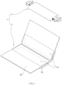
- FIG. 1 is an assembly view illustrating a secondary battery 1 according to embodiments of the present invention.
- the secondary battery 1 may include an electrode assembly 2.
- An electrode and a separator may be alternately stacked to provide the electrode assembly 2.
- the electrode assembly 2 may be provided by alternately stacking electrodes (e.g., a positive electrode and a negative electrode) with a separator therebetween.
- the electrode assembly 2 may include electrode tabs, and the electrode tabs may be connected to the positive electrode and the negative electrode, respectively.
- the electrode assembly 2 may include an electrode lead.
- the electrode lead may be connected to the electrode tabs and electrically connect the electrodes to the outside.
- the electrode assembly 2 is not limited to those described above, and may be described in the general context of the relevant technical field.
- the secondary battery 1 may include a battery case 3.
- the battery case 3 may accommodate the electrode assembly 2 therein.
- the battery case 3 may be a pouch type battery case.
- the electrode assembly 2 may be accommodated in the battery case 3, and an edge of the battery case 3 may be sealed.
- the battery case 3 may include an accommodation part 10.
- the accommodation part 10 may be a portion in which the electrode assembly 2 is accommodated and seated in the battery case 3.
- the accommodation part 10 may define an accommodation space in which the electrode assembly 2 may be accommodated.
- the battery case 3 may include a cup part 20.
- the cup part 20 may be provided to have a shape surrounding the accommodation part 10.
- the accommodation part 10 may be provided.
- the battery case 3 may include a degassing part 30.
- the degassing part 30 may be provided on a side portion of the cup part 20 and discharge a gas generated in the cup part 20 through a degassing hole.
- the battery case 3 may include an edge 40.
- a portion of the degassing part 30 may be cut from the battery case 3 after a degassing process is performed. As the portion of the degassing part 30 is cut, the degassing part 30 may be decreased in length, and the secondary battery 1 may be reduced in volume. A remaining portion of the degassing part 30 after the portion thereof is cut may be the edge 40.
- the edge 40 may be preferably folded.
- the method for manufacturing the secondary battery 1 may include a folding process of folding the edge 40 according to S100.
- the edge 40 may be folded multiple times.
- the edge 40 may be folded twice using a double side folding (DSF) process.
- the edge 40 may include a first folding part 41 and a second folding part 42.
- the first folding part 41 is a portion folded at a position that is relatively closer to an end of the edge 40
- the second folding part 42 is a portion folded at a position that is relatively closer to the cup part 20.
- the edge 40 may be primarily folded on the basis of the first folding part 41, and then the edge 40 may be secondarily folded on the basis of the second folding part 42.
- the adhesive member 100 may be attached to the secondary battery 1 through the attaching process.
- the adhesive member 100 may be attached while covering a portion of the edge 40 and a portion of the cup part 20.
- the adhesive member 100 may be attached to the edge 40 so that the edge 40 is fixed in a state of being folded toward the cup part 20.
- the attaching process may include attaching a plurality of adhesive members 100 to the edge 40 so as to be spaced apart from each other.
- the adhesive member 100 may be provided in plurality, and the plurality of adhesive members 100 may be attached at intervals along the edge 40.
- the adhesive member 100 may be provided in three, and the three adhesive members 100 may be attached at intervals along the edge 40.
- the number of the adhesive members 100 is not limited to the foregoing example.
- the non-attachment area 300 may be formed.
- the non-attachment area 300 to which the adhesive member 100 is not attached may be formed between the plurality of adhesive members 100.
- the pressing apparatus 200 may press the non-attachment area 300 at a side of an edge 40 in a direction in which a thickness t of the non-attachment area 300 is decreased in a lateral direction of the secondary battery 1.
- the pressing apparatus 200 may include the protrusion 220.
- the protrusion 220 may protrude from the body 210 toward the edge 40 so as to press at least a portion of a remaining area (or non-attachment area 300) except a partial area (or attachment area) to which the adhesive member 100 is attached.
- the protrusion 220 may protrude from the body 210 to form a predetermined pattern.
- the predetermined pattern may be determined according to a pressing area (e.g., pressing area 400), which is pressed by the protrusion 220, of the non-attachment area 300.
- the pressing apparatus 200 may be provided to be capable of being heated.
- the protrusion 220 which is provided so as to press at least a portion of the non-attachment area 300, may be provided to be heated to at least a temperature exceeding room temperature.
- the protrusion 220 of the pressing apparatus 200 may protrude to form a pattern provided so that an area, which is disposed between the adhesive members 100, of the non-attachment area 300 is at least pressed.
- the protrusion 220 may protrude to form a pattern as in FIG. 5 , so that an area (or pressing area 400), which is disposed between the adhesive members 100, of the non-attachment area 300 of the edge 40 is mainly pressed.
- the protrusion 220 may protrude to formed a pattern provided so as to press the area between the adhesive members 100.
- the area (or pressing area 400) between the adhesive members 100 may be an area in which a difference in thickness between the non-attachment area 300 and the attachment area to which the adhesive member 100 is attached is greatest.
- a thickness of the non-attachment area 300 having the greatest thickness difference and a thickness of the attachment area, to which the adhesive member 100 is attached may be uniform.
- a partial area of the non-attachment area 300 may be thermo-compressed.
- at least a partial area (e.g., area between the adhesive members 100) of the non-attachment area 300, to which the adhesive members 100 are not attached, of the edge 40 may be thermo-compressed by being heated and pressed by the protrusion 220 protruding to form a predetermined pattern.
- a thickness of at least an area, which is disposed between the adhesive members 100, of the non-attachment area 300, to which the adhesive member 100 is not attached, of the folded edge 40 may correspond to or be less than the thickness of the attachment area to which the adhesive member 100 is attached.
- a protrusion 220a of the pressing apparatus 200a may protrude to form a pattern provided so that the non-attachment area 300a is at least pressed.
- the protrusion 220a may protrude to form a pattern as in FIG. 7 so that the entirety of the non-attachment area 300a of an edge 40a is pressed.
- the protrusion 220 may protrude to form a pattern corresponding to a shape of the non-attachment area 300a so that the entirety of the non-attachment area 300a is pressed.
- the pressing area 400a may be an area corresponding to the non-attachment area 300. As the protrusion 220a presses the pressing area 400a, a difference in thickness between the non-attachment area 300a and an attachment area to which an adhesive member 100a is attached may be minimized.
- the pressing apparatus 200a may press the pressing area 400a in a state in which at least the protrusion 220a is heated.
- the protrusion 220a performs the pressing in the heated state, the difference in thickness between the non-attachment area 300a and the attachment area to which the adhesive member 100a is attached may be reduced more effectively.
- the non-attachment area 300a may be thermo-compressed.
- the non-attachment area 300a, to which the adhesive member 100a is not attached, of the edge 40a may be thermo-compressed by being heated and pressed by the protrusion 220a protruding to form a predetermined pattern.
- the thickness of the non-attachment area 300a, to which the adhesive member 100a is not attached, of the folded edge 40a may correspond to or be less than the thickness of the attachment area to which the adhesive member 100a is attached.
- an occurrence of a physical interference caused by the difference in thickness between the areas of the secondary battery 1a may be minimized, and spatial efficiency may be improved when the secondary batteries 1a are stacked.
- a protrusion 220b of the pressing apparatus 200b may protrude to form a pattern provided so that the non-attachment area 300b is at least pressed, and is pressed with a gap from the attachment area to which the adhesive member 100b is attached.
- the protrusion 220b may protrude to form a pattern as in FIG. 9 so that a portion of the non-attachment area 300b of an edge 40b is pressed.
- the protrusion 220b may protrude to form a pattern provided so that a portion of the non-attachment area 300b is pressed, and a portion, which is adjacent to the adhesive member 100b, of the non-attachment area 300b is not pressed.
Landscapes
- Chemical & Material Sciences (AREA)
- Chemical Kinetics & Catalysis (AREA)
- Electrochemistry (AREA)
- General Chemical & Material Sciences (AREA)
- Engineering & Computer Science (AREA)
- Manufacturing & Machinery (AREA)
- Secondary Cells (AREA)
- Sealing Battery Cases Or Jackets (AREA)
Abstract
Description
- The present application claims the benefit of the priority of
Korean Patent Application Nos. 10-2022-0127431, filed on October 5, 2022 10-2023-0060696, filed on May 10, 2023 - The present invention relates to a secondary battery, a method for manufacturing the secondary battery, and a pressing apparatus used for the method.
- Research on and development for electric power generation based on eco-friendly energy sources are carried out so as to solve the problems of the environmental pollution and solve the energy source problems caused by depletion of oil resources. In particular, research on secondary batteries is actively carried out, and the research is conducted on various aspects such as the materials, structures, processes, and stability of the secondary batteries.
- With regard to the structure of the secondary batteries, the secondary batteries may be classified into a pouch type, a prismatic type, a cylindrical type, and the like, according to the shape of battery cases for accommodating electrode assemblies. In the pouch type secondary batteries, a sealing part or degassing part formed on an edge occupies a space, and thus a double side folding (DSF) process of folding the sealing part or the degassing part may be performed for spatial efficiency.
- According to the related art, folding is followed by taping when performing the DSF process. Here, taping the entire surface of the edge is disadvantageous in the aspects of lead part flame propagation retardation. In addition, partially taping the edge may cause a difference in thickness between a non-attachment area, to which a tape is not attached, and a partially taped area, and the difference in thickness may be likely to cause a physical interference in a subsequent process.
- An object of the present invention for solving the above problems is to provide a secondary battery capable of minimizing a difference in thickness between a non-attachment area to which a tape is not attached, and an area to which a tape is attached, so as to prevent a physical interference, a method for manufacturing the secondary battery, and a pressing apparatus used for the method.
- A method for manufacturing a secondary battery according to an embodiment of the present invention may manufacture the secondary battery including an electrode assembly, and a battery case provided to accommodate the electrode assembly and having a sealed edge. The method for manufacturing the secondary battery may include a folding process of folding the edge, an attaching process of attaching an adhesive member to the folded edge, and a pressing process of pressing at least a partial area of a non-attachment area, to which the adhesive member is not attached, of the edge.
- A pressing apparatus according to an embodiment of the present invention may press a secondary battery including an electrode assembly, and a battery case provided to accommodate the electrode assembly and having a sealed edge, wherein an adhesive member is attached to a partial area of the edge. The pressing apparatus may include a body provided so that a distance from the edge varies, and a protrusion protruding from the body toward the edge so as to press at least a portion of a remaining area except for the partial area.
- A secondary battery according to an embodiment of the present invention may include an electrode assembly, a battery case provided to accommodate the electrode assembly and having a folded edge, and an adhesive member attached to a partial area of the folded edge, wherein at least a partial area of a non-attachment area, to which the adhesive member is not attached, of the edge is pressed.
- According to the preferred embodiment of the present invention, the difference in thickness between the areas of the secondary battery may be minimized.
- According to the preferred embodiment of the present invention, the edge of the secondary battery may be prevented from unnecessarily protruding.
- According to the preferred embodiment of the present invention, the occurrence of the physical interference caused by the protruding and the difference in thickness between the areas of the secondary battery may be minimized.
- According to the preferred embodiment of the present invention, the spatial efficiency may be improved when the secondary batteries are stacked.
-
-
FIG. 1 is an assembly view illustrating a secondary battery according to an embodiment of the present invention. -
FIG. 2 is a flowchart illustrating a method for manufacturing a secondary battery according to an embodiment of the present invention. -
FIG. 3 is a longitudinal cross-sectional view illustrating a secondary battery according to an embodiment of the present invention when viewed in one direction. -
FIG. 4a is a plan view illustrating a non-attachment area of a secondary battery according to an embodiment of the present invention. -
FIG. 4b is a perspective view illustrating a non-attachment area of a secondary battery according to an embodiment of the present invention. -
FIG. 5 is a side view illustrating a state in which a non-attachment area of a secondary battery is pressed using a pressing apparatus according to a first embodiment of the present invention when viewed in another direction. -
FIG. 6 is a plan view illustrating a pressing area on which the pressing apparatus presses the secondary battery according to the first embodiment of the present invention. -
FIG. 7 is a side view illustrating a state in which a non-attachment area of a secondary battery is pressed using a pressing apparatus according to a second embodiment of the present invention when viewed in another direction. -
FIG. 8 is a plan view illustrating a pressing area on which the pressing apparatus presses the secondary battery according to the second embodiment of the present invention. -
FIG. 9 is a side view illustrating a state in which a non-attachment area of a secondary battery is pressed using a pressing apparatus according to a third embodiment of the present invention when viewed in another direction. -
FIG. 10 is a plan view illustrating a pressing area on which the pressing apparatus presses the secondary battery according to the third embodiment of the present invention. -
FIG. 11 is a side view illustrating a state in which a non-attachment area of a secondary battery is pressed using a pressing apparatus according to a fourth embodiment of the present invention when viewed in another direction. -
FIG. 12 is a plan view illustrating a pressing area on which the pressing apparatus presses the secondary battery according to the fourth embodiment of the present invention. - Hereinafter, preferred embodiments of the present invention will be described in detail with reference to the accompanying drawings to enable those skilled in the art to which the present invention pertains to easily carry out the present invention. The present invention may, however, be embodied in different forms and should not be construed as limited by the embodiments set forth herein.
- The parts unrelated to the description, or the detailed descriptions of related well-known art that may unnecessarily obscure subject matters of the present invention, will be ruled out in order to clearly describe the present invention. Like reference numerals refer to like elements throughout the whole specification.
- Moreover, terms or words used in this specification and claims should not be restrictively interpreted as ordinary meanings or dictionary-based meanings, but should be interpreted as meanings and concepts conforming to the scope of the present invention on the basis of the principle that an inventor can properly define the concept of a term to describe and explain his or her invention in the best ways.
-
FIG. 1 is an assembly view illustrating asecondary battery 1 according to embodiments of the present invention. - The
secondary battery 1 may include anelectrode assembly 2. An electrode and a separator may be alternately stacked to provide theelectrode assembly 2. For example, theelectrode assembly 2 may be provided by alternately stacking electrodes (e.g., a positive electrode and a negative electrode) with a separator therebetween. Theelectrode assembly 2 may include electrode tabs, and the electrode tabs may be connected to the positive electrode and the negative electrode, respectively. Theelectrode assembly 2 may include an electrode lead. The electrode lead may be connected to the electrode tabs and electrically connect the electrodes to the outside. Theelectrode assembly 2 is not limited to those described above, and may be described in the general context of the relevant technical field. - The
secondary battery 1 may include abattery case 3. Thebattery case 3 may accommodate theelectrode assembly 2 therein. For example, thebattery case 3 may be a pouch type battery case. Theelectrode assembly 2 may be accommodated in thebattery case 3, and an edge of thebattery case 3 may be sealed. - The
battery case 3 may include anaccommodation part 10. Theaccommodation part 10 may be a portion in which theelectrode assembly 2 is accommodated and seated in thebattery case 3. Theaccommodation part 10 may define an accommodation space in which theelectrode assembly 2 may be accommodated. - The
battery case 3 may include acup part 20. Thecup part 20 may be provided to have a shape surrounding theaccommodation part 10. As thecup part 20 is provided, theaccommodation part 10 may be provided. - The
battery case 3 may include adegassing part 30. The degassingpart 30 may be provided on a side portion of thecup part 20 and discharge a gas generated in thecup part 20 through a degassing hole. - The
battery case 3 may include anedge 40. A portion of thedegassing part 30 may be cut from thebattery case 3 after a degassing process is performed. As the portion of thedegassing part 30 is cut, the degassingpart 30 may be decreased in length, and thesecondary battery 1 may be reduced in volume. A remaining portion of thedegassing part 30 after the portion thereof is cut may be theedge 40. - As described above, as the portion of the
degassing part 30 is cut to decrease the length of thedegassing part 30, the volume of thesecondary battery 1 may be reduced. However, when theedge 40 is left as it is, the spatial efficiency of thesecondary battery 1 may be deteriorated. Thus, theedge 40 may be preferably folded. - Hereinafter, embodiments will be described which are capable of folding the
edge 40, attaching an adhesive member to the foldededge 40, and pressing at least a portion of a non-attachment area, to which the adhesive member is not attached, so that the spatial efficiency of thesecondary battery 1 is stably improved. -
FIG. 2 is a flowchart illustrating a method for manufacturing thesecondary battery 1 according to embodiments of the present invention. The method for manufacturing thesecondary battery 1 inFIG. 2 will be described with reference toFIG. 3 illustrating a longitudinal cross-sectional view of thesecondary battery 1 when viewed in one direction, andFIG. 4a and4b illustrating a plan view and a perspective view of anon-attachment area 300 of thesecondary battery 1. The same or similar description as or to the foregoing description may also apply to this embodiment. - The method for manufacturing the
secondary battery 1 may include a folding process of folding theedge 40 according to S100. - The
edge 40 may be folded multiple times. For example, theedge 40 may be folded twice using a double side folding (DSF) process. Specifically, theedge 40 may include afirst folding part 41 and asecond folding part 42. Thefirst folding part 41 is a portion folded at a position that is relatively closer to an end of theedge 40, and thesecond folding part 42 is a portion folded at a position that is relatively closer to thecup part 20. Theedge 40 may be primarily folded on the basis of thefirst folding part 41, and then theedge 40 may be secondarily folded on the basis of thesecond folding part 42. - The method for manufacturing the
secondary battery 1 may include an attaching process of attaching anadhesive member 100 to the foldededge 40 according to S200. - The
adhesive member 100 may be attached to thesecondary battery 1 through the attaching process. For example, theadhesive member 100 may be attached while covering a portion of theedge 40 and a portion of thecup part 20. Theadhesive member 100 may be attached to theedge 40 so that theedge 40 is fixed in a state of being folded toward thecup part 20. - The attaching process may include attaching a plurality of
adhesive members 100 to theedge 40 so as to be spaced apart from each other. For example, theadhesive member 100 may be provided in plurality, and the plurality ofadhesive members 100 may be attached at intervals along theedge 40. For specific example, theadhesive member 100 may be provided in three, and the threeadhesive members 100 may be attached at intervals along theedge 40. However, the number of theadhesive members 100 is not limited to the foregoing example. - In the attaching process, the
non-attachment area 300 may be formed. For example, when the plurality ofadhesive members 100 are attached to theedge 40 so as to be spaced apart from each other, thenon-attachment area 300 to which theadhesive member 100 is not attached may be formed between the plurality ofadhesive members 100. - Referring to
FIG. 4a , thenon-attachment area 300 may be formed on a portion of thecup part 20. For example, thenon-attachment area 300 may be formed on an upper portion of thecup part 20 of thesecondary battery 1. In addition, referring toFIG. 4b , thenon-attachment area 300 may be formed on a portion of theedge 40. For example, thenon-attachment area 300 may be formed on a portion of a side portion of theedge 40. - The following descriptions of a thickness t of the
non-attachment area 300 may correspond to descriptions of a thickness of theedge 40. - The thickness t of the non-attachment area 300 (or the
edge 40 corresponding to the non-attachment area 300) before a pressing process for thenon-attachment area 300 may be greater than a thickness of an attachment area to which theadhesive member 100 is attached. The thickness t may be a thickness t of theedge 40 in a state in which theedge 40 is folded multiple times. The thickness t of theedge 40 may be a thickness in a lateral direction. Hereinafter, a thickness may be the thickness t of thenon-attachment area 300. - The attaching process may include attaching an adhesive member having a melting point higher than a temperature exceeding room temperature.
- The method for manufacturing the
secondary battery 1 may include a pressing process of pressing at least a partial area of thenon-attachment area 300, to which theadhesive member 100 is not attached, of theedge 40 according to S300. - The pressing process may include pressing a portion of the
secondary battery 1 by using apressing apparatus 200. Thepressing apparatus 200 may be movable relative to thesecondary battery 1. Thepressing apparatus 200 may include a protruding portion (e.g., aprotrusion 220 inFIG. 5 ) so as to press at least a portion of thenon-attachment area 300 of thesecondary battery 1. - The pressing process may include pressing a portion of the
secondary battery 1 by using thepressing apparatus 200 in a direction in which the thickness t of the portion of thesecondary battery 1 decreases. For example, thepressing apparatus 200 may press the portion of thesecondary battery 1 in a direction facing the cup part 120. In other words, thepressing apparatus 200 may press thenon-attachment area 300 of theedge 40 from a lateral side of theedge 40 of thesecondary battery 1. - The pressing process may include pressing at least a partial area of the
non-attachment area 300 formed between the plurality ofadhesive members 100 by using thepressing apparatus 200. - The pressing process may include pressing the at least a partial area with a gap from the attachment area, to which the
adhesive member 100 is attached, by using thepressing apparatus 200. - The pressing process may include pressing the at least a partial area at a temperature exceeding room temperature by using the
pressing apparatus 200. - The thickness t of the non-attachment area 300 (or the
edge 40 corresponding to the non-attachment area 300) after the pressing process may not be greater than the thickness of the attachment area to which theadhesive member 100 is attached. For example, the pressing may be performed by using thepressing apparatus 200 in a direction in which the thickness t decreases, so that the thickness t of thenon-attachment area 300 corresponds to the thickness of the attachment area, to which theadhesive member 100 is attached, or is less than the thickness of the attachment area to which theadhesive member 100 is attached. - The corresponding thickness may include the same thickness, and, even though not the same, also include a thickness of a portion protruding to the outside within a small range.
- In other words, the
non-attachment area 300 after the pressing process may not protrude outward from the attachment area to which theadhesive member 100 is attached. Accordingly, a partial area (e.g., non-attachment area 300) of theedge 40 of the secondary battery may be prevented from unnecessarily protruding. -
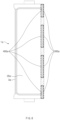
FIG. 5 is a side view illustrating a state in which anon-attachment area 300 of asecondary battery 1 is pressed using apressing apparatus 200 according to a first embodiment of the present invention when viewed in another direction.FIG. 6 is a plan view illustrating apressing area 400 on which thepressing apparatus 200 presses thesecondary battery 1 according to the first embodiment of the present invention. The same or similar description as or to the foregoing description may also apply to this embodiment. - Referring to
FIG. 5 and the plan view inFIG. 6 , thepressing apparatus 200 may press thenon-attachment area 300 at a side of anedge 40 in a direction in which a thickness t of thenon-attachment area 300 is decreased in a lateral direction of thesecondary battery 1. - The
pressing apparatus 200 may press thesecondary battery 1. Thesecondary battery 1 may include anelectrode assembly 2, and abattery case 3 provided to accommodate theelectrode assembly 2 and having a sealed edge. Anadhesive member 100 may be attached to a partial area of theedge 40. - The
pressing apparatus 200 may include abody 210. For example, thebody 210 may be provided so that a distance from theedge 40 varies. In other words, thebody 210 may be movable relative to theedge 40. - The
pressing apparatus 200 may include theprotrusion 220. For example, theprotrusion 220 may protrude from thebody 210 toward theedge 40 so as to press at least a portion of a remaining area (or non-attachment area 300) except a partial area (or attachment area) to which theadhesive member 100 is attached. Theprotrusion 220 may protrude from thebody 210 to form a predetermined pattern. For example, the predetermined pattern may be determined according to a pressing area (e.g., pressing area 400), which is pressed by theprotrusion 220, of thenon-attachment area 300. - The
pressing apparatus 200 may be provided to be capable of being heated. For example, theprotrusion 220, which is provided so as to press at least a portion of thenon-attachment area 300, may be provided to be heated to at least a temperature exceeding room temperature. - The
protrusion 220 of thepressing apparatus 200 may protrude to form a pattern provided so that an area, which is disposed between theadhesive members 100, of thenon-attachment area 300 is at least pressed. For example, theprotrusion 220 may protrude to form a pattern as inFIG. 5 , so that an area (or pressing area 400), which is disposed between theadhesive members 100, of thenon-attachment area 300 of theedge 40 is mainly pressed. Specifically, theprotrusion 220 may protrude to formed a pattern provided so as to press the area between theadhesive members 100. - The area (or pressing area 400) between the
adhesive members 100 may be an area in which a difference in thickness between thenon-attachment area 300 and the attachment area to which theadhesive member 100 is attached is greatest. In this case, as theprotrusion 220 presses the area between theadhesive members 100, a thickness of thenon-attachment area 300 having the greatest thickness difference and a thickness of the attachment area, to which theadhesive member 100 is attached, may be uniform. - In the
pressing apparatus 200, thepressing apparatus 200 may press thepressing area 400 in a state in which at least theprotrusion 220 of thepressing apparatus 200 is heated to a temperature exceeding room temperature. When theprotrusion 220 performs the pressing in the heated state, the thickness of thenon-attachment area 300 having the greatest thickness difference and the thickness of the attachment area, to which theadhesive member 100 is attached, may be made uniform more effectively. - As described above, not only the thickness of the
non-attachment area 300 and the thickness of the attachment area may be uniform, but also spatial efficiency may be improved even when the thickness t of thenon-attachment area 300 is less than the thickness of the attachment area to which theadhesive member 100 is attached. - In the
secondary battery 1 pressed by thepressing apparatus 200, a partial area of thenon-attachment area 300 may be thermo-compressed. For example, at least a partial area (e.g., area between the adhesive members 100) of thenon-attachment area 300, to which theadhesive members 100 are not attached, of theedge 40 may be thermo-compressed by being heated and pressed by theprotrusion 220 protruding to form a predetermined pattern. - As the area, which is disposed between the
adhesive members 100, of thenon-attachment area 300 is thermo-compressed through the heating and the pressing, a thickness of at least an area, which is disposed between theadhesive members 100, of thenon-attachment area 300, to which theadhesive member 100 is not attached, of the foldededge 40 may correspond to or be less than the thickness of the attachment area to which theadhesive member 100 is attached. - According to the foregoing description, an occurrence of a physical interference caused by the difference in thickness between the areas of the
secondary battery 1 may be minimized, and spatial efficiency may be improved when thesecondary batteries 1 are stacked. -
FIG. 7 is a side view illustrating a state in which anon-attachment area 300a of asecondary battery 1a is pressed using apressing apparatus 200a according to a second embodiment of the present invention when viewed in another direction.FIG. 8 is a plan view illustrating apressing area 400a on which thepressing apparatus 200a presses thesecondary battery 1a according to the second embodiment of the present invention. The same or similar description as or to the foregoing description may also apply to this embodiment. - A
protrusion 220a of thepressing apparatus 200a may protrude to form a pattern provided so that thenon-attachment area 300a is at least pressed. For example, theprotrusion 220a may protrude to form a pattern as inFIG. 7 so that the entirety of thenon-attachment area 300a of an edge 40a is pressed. Specifically, theprotrusion 220 may protrude to form a pattern corresponding to a shape of thenon-attachment area 300a so that the entirety of thenon-attachment area 300a is pressed. Thepressing area 400a may be an area corresponding to thenon-attachment area 300. As theprotrusion 220a presses thepressing area 400a, a difference in thickness between thenon-attachment area 300a and an attachment area to which anadhesive member 100a is attached may be minimized. - The
pressing apparatus 200a may press thepressing area 400a in a state in which at least theprotrusion 220a is heated. When theprotrusion 220a performs the pressing in the heated state, the difference in thickness between thenon-attachment area 300a and the attachment area to which theadhesive member 100a is attached may be reduced more effectively. - In the
secondary battery 1a pressed by thepressing apparatus 200a, thenon-attachment area 300a may be thermo-compressed. For example, thenon-attachment area 300a, to which theadhesive member 100a is not attached, of the edge 40a may be thermo-compressed by being heated and pressed by theprotrusion 220a protruding to form a predetermined pattern. - As the
non-attachment area 300a is thermo-compressed through the heating and the pressing, the thickness of thenon-attachment area 300a, to which theadhesive member 100a is not attached, of the folded edge 40a may correspond to or be less than the thickness of the attachment area to which theadhesive member 100a is attached. - According to the foregoing description, an occurrence of a physical interference caused by the difference in thickness between the areas of the
secondary battery 1a may be minimized, and spatial efficiency may be improved when thesecondary batteries 1a are stacked. -
FIG. 9 is a side view illustrating a state in which anon-attachment area 300b of asecondary battery 1b is pressed using apressing apparatus 200b according to a third embodiment of the present invention when viewed in another direction.FIG. 10 is a plan view illustrating apressing area 400b on which thepressing apparatus 200b presses thesecondary battery 1a according to the third embodiment of the present invention. The same or similar description as or to the foregoing description may also apply to this embodiment. - As described above, a pressing process including pressing at least a partial area of the
non-attachment area 300b with a gap from an attachment area to which anadhesive member 100b is attached will be described. - A
protrusion 220b of thepressing apparatus 200b may protrude to form a pattern provided so that thenon-attachment area 300b is at least pressed, and is pressed with a gap from the attachment area to which theadhesive member 100b is attached. For example, theprotrusion 220b may protrude to form a pattern as inFIG. 9 so that a portion of thenon-attachment area 300b of an edge 40b is pressed. Specifically, theprotrusion 220b may protrude to form a pattern provided so that a portion of thenon-attachment area 300b is pressed, and a portion, which is adjacent to theadhesive member 100b, of thenon-attachment area 300b is not pressed. Thepressing area 400b may be an area included in thenon-attachment area 300b. As theprotrusion 220b presses thepressing area 400b, a difference in thickness between thepressing area 400b of thenon-attachment area 300b and the attachment area to which theadhesive member 100a is attached may be minimized. - The
pressing apparatus 200b may press thepressing area 400b in a state in which at least theprotrusion 220b is heated. When theprotrusion 220b performs the pressing in the heated state, the difference in thickness between thepressing area 400b of thenon-attachment area 300b and the attachment area to which theadhesive member 100b is attached may be reduced more effectively. - In the
secondary battery 1b pressed by thepressing apparatus 200b, thepressing area 400b of thenon-attachment area 300b may be thermo-compressed. For example, thenon-attachment area 300b, to which theadhesive member 100b is not attached, of the edge 40b may be thermo-compressed, and an area, which corresponds to thepressing area 400b, of thenon-attachment area 300b may be thermo-compressed by being heated and pressed by theprotrusion 220b protruding to form a predetermined pattern. - As the
pressing area 400b is thermo-compressed through the heating and the pressing, a thickness of thepressing area 400b of the folded edge 40b may correspond to or be less than a thickness of the attachment area to which theadhesive member 100 is attached. - According to the foregoing description, an occurrence of a physical interference caused by the difference in thickness between the areas of the
secondary battery 1b may be minimized, and spatial efficiency may be improved when thesecondary batteries 1b are stacked. -
FIG. 11 is a side view illustrating a state in which anon-attachment area 300c of asecondary battery 1c is pressed using apressing apparatus 200c according to a fourth embodiment of the present invention when viewed in another direction.FIG. 12 is a plan view illustrating apressing area 400c on which thepressing apparatus 200c presses thesecondary battery 1c according to the fourth embodiment of the present invention. The same or similar description as or to the foregoing description may also apply to this embodiment. - As described above, a pressing process including pressing the
non-attachment area 300c and at least a portion of an attachment area to which anadhesive member 100c is attached will be described. - A
protrusion 220c of thepressing apparatus 200c may protrude to form a pattern provided so that thenon-attachment area 300c and a portion of the attachment area to which theadhesive member 100c is attached are at least pressed. For example, theprotrusion 220c may protrude to form a pattern as inFIG. 11 so that the entirety of thenon-attachment area 300c of an edge 40c is pressed, and an area, which is adjacent to thenon-attachment area 300c, of theadhesive member 100c is also pressed. Specifically, theprotrusion 220c may protrude to form a pattern provided so as to cover thenon-attachment area 300c and a partial area, to which theadhesive member 100c is attached, when viewed from an upper side. Thepressing area 400c may be an area including thenon-attachment area 300c. As theprotrusion 220c presses thepressing area 400c, a difference in thickness between thenon-attachment area 300c and the attachment area to which theadhesive member 100c is attached may be minimized. - The
pressing apparatus 200c may press thepressing area 400c in a state in which at least theprotrusion 220c is heated. When theprotrusion 220c performs the pressing in the heated state, the difference in thickness between thenon-attachment area 300c and the attachment area to which theadhesive member 100c is attached may be reduced more effectively. - When the
protrusion 220c of thepressing apparatus 200c also presses a portion of theadhesive member 100c as described above, theadhesive member 100c may be an adhesive member having a melting point higher than a temperature exceeding room temperature in order to prevent damage to theadhesive member 100c. In other words, theadhesive member 100c may be an adhesive member having a melting point higher than a temperature corresponding to the heated state of theprotrusion 220c. - In the
secondary battery 1c pressed by thepressing apparatus 200c, thepressing area 400c may be thermo-compressed. For example, thenon-attachment area 300c, to which theadhesive member 100c is not attached, of the edge 40c may be at least thermo-compressed, and an area corresponding to thepressing area 400c may be thermo-compressed by being heated and pressed by theprotrusion 220c protruding to form a predetermined pattern. - As the
pressing area 400c is thermo-compressed through the heating and the pressing, a thickness of thepressing area 400c of the folded edge 40c may correspond to or be less than a thickness of the attachment area to which theadhesive member 100c is attached. - According to the foregoing description, an occurrence of a physical interference caused by the difference in thickness between the areas of the
secondary battery 1c may be minimized, and spatial efficiency may be improved when thesecondary batteries 1c are stacked. - Although the present invention has been described with reference to the limited embodiments and drawings, the present invention is not limited thereto and may be variously implemented by those of ordinary skill in the art to which the present invention pertains, within the technical idea of the present invention and an equivalent of the appended claims.
-
- 1, 1a, 1b, 1c: Secondary battery
- 2: Electrode assembly
- 3: Battery case
- 10: Accommodation part
- 20: Cup part
- 30: Degassing part
- 40: Edge
- 41: First folding part
- 42: Second folding part
- 100, 100a, 100b, 100c: Adhesive member
- 200, 200a, 200b, 200c: Pressing apparatus
- 210, 210a, 210b, 210c: Body
- 220, 220a, 220b, 220c: Protrusion
- 300, 300a, 300b, 300c: Non-attachment area
- 400, 400a, 400b, 400c: Pressing area
Claims (12)
- A method for manufacturing a secondary battery that comprises an electrode assembly and a battery case configured to accommodate the electrode assembly and having a sealed edge, the method comprising:a folding process of folding the edge;an attaching process of attaching an adhesive member to the folded edge; anda pressing process of pressing at least a partial area of a non-attachment area, to which the adhesive member is not attached, of the edge.
- The method of claim 1, wherein the attaching process comprises attaching a plurality of adhesive members to the edge so as to be spaced apart from each other, and
the pressing process comprises pressing at least a partial area of the non-attachment area formed between the plurality of adhesive members. - The method of claim 1, wherein the pressing process comprises pressing the at least a partial area with a gap from an attachment area to which the adhesive member is attached.
- The method of claim 1, wherein the pressing process comprises pressing the at least a partial area at a temperature exceeding room temperature.
- The method of claim 1, wherein the pressing process comprises pressing the non-attachment area and at least a portion of an attachment area to which the adhesive member is attached.
- The method of claim 5, wherein the pressing process comprises performing the pressing at a temperature exceeding room temperature.
- The method of claim 6, wherein the attaching process comprises attaching the adhesive member having a melting point higher than the temperature exceeding room temperature.
- A pressing apparatus for pressing a secondary battery that comprises an electrode assembly and a battery case configured to accommodate the electrode assembly and having a sealed edge, wherein an adhesive member is attached to a partial area of the edge, the pressing apparatus comprising:a body provided so that a distance from the edge varies; anda protrusion protruding from the body toward the edge so as to press at least a portion of a remaining area except for the partial area.
- The pressing apparatus of claim 8, wherein the protrusion is provided to be heated.
- The pressing apparatus of claim 8, wherein the protrusion protrudes from the body to form a predetermined pattern.
- A secondary battery comprising:an electrode assembly;a battery case configured to accommodate the electrode assembly and having a folded edge; andan adhesive member attached to a partial area of the folded edge,wherein at least a partial area of a non-attachment area, to which the adhesive member is not attached, of the edge is pressed.
- The secondary battery of claim 11, wherein a thickness of the non-attachment area, to which the adhesive member is not attached, of the folded edge corresponds to a thickness of the partial area to which the adhesive member is attached.
Applications Claiming Priority (3)
| Application Number | Priority Date | Filing Date | Title |
|---|---|---|---|
| KR20220127431 | 2022-10-05 | ||
| KR1020230060696A KR20240047899A (en) | 2022-10-05 | 2023-05-10 | Secondary battery, manufacturing method of the secondary battery, and pressing device used in the method |
| PCT/KR2023/011615 WO2024075964A1 (en) | 2022-10-05 | 2023-08-07 | Secondary battery, manufacturing method for same secondary battery, and pressing device used for same manufacturing method |
Publications (2)
| Publication Number | Publication Date |
|---|---|
| EP4579891A1 true EP4579891A1 (en) | 2025-07-02 |
| EP4579891A4 EP4579891A4 (en) | 2026-03-25 |
Family
ID=90608538
Family Applications (1)
| Application Number | Title | Priority Date | Filing Date |
|---|---|---|---|
| EP23875034.3A Pending EP4579891A4 (en) | 2022-10-05 | 2023-08-07 | Secondary battery, manufacturing process for the same secondary battery and pressing device for this manufacturing process |
Country Status (4)
| Country | Link |
|---|---|
| EP (1) | EP4579891A4 (en) |
| JP (1) | JP2025533333A (en) |
| CN (1) | CN119948678A (en) |
| WO (1) | WO2024075964A1 (en) |
Family Cites Families (13)
| Publication number | Priority date | Publication date | Assignee | Title |
|---|---|---|---|---|
| JP3829502B2 (en) * | 1998-10-30 | 2006-10-04 | ソニー株式会社 | Non-aqueous electrolyte battery |
| US9498918B2 (en) * | 2012-09-18 | 2016-11-22 | Ev Group E. Thallner Gmbh | Method and device for embossing |
| KR102112670B1 (en) * | 2015-10-28 | 2020-05-19 | 주식회사 엘지화학 | Battery Cell of Venting Structure Using Taping |
| CN205122651U (en) * | 2015-11-02 | 2016-03-30 | 宁德新能源科技有限公司 | Soft -packed lithium ion battery |
| KR102143627B1 (en) * | 2017-11-21 | 2020-08-11 | 삼성에스디아이 주식회사 | Pouch type secondary battery |
| JP7177852B2 (en) * | 2018-05-04 | 2022-11-24 | エーファウ・グループ・エー・タルナー・ゲーエムベーハー | Methods for stamping and embossing |
| KR102148997B1 (en) * | 2019-12-03 | 2020-08-28 | 주식회사 와이에이치티 | Folding apparature of folding system for folding terrace of secondary battery cell |
| KR20210156712A (en) * | 2020-06-18 | 2021-12-27 | 김광열 | Method for folding the side of battery cell |
| KR102564839B1 (en) * | 2020-08-19 | 2023-08-09 | 주식회사 엘지에너지솔루션 | The Pouch Type Secondary Battery And The Battery Module |
| EP4199202B1 (en) * | 2020-08-19 | 2026-05-20 | Lg Energy Solution Ltd | POUCH-STYLE BATTERY HOUSING AND POUCH-STYLE SECONDARY BATTERY |
| KR20220127144A (en) * | 2021-03-10 | 2022-09-19 | 에스케이온 주식회사 | Apparatus for Manufacturing Battery Cell |
| KR20220127145A (en) * | 2021-03-10 | 2022-09-19 | 에스케이온 주식회사 | Apparatus for Manufacturing Battery Cell |
| CN216084993U (en) * | 2021-07-28 | 2022-03-18 | 惠州淏海能源有限公司 | Edge folding structure of flexible package lithium battery |
-
2023
- 2023-08-07 EP EP23875034.3A patent/EP4579891A4/en active Pending
- 2023-08-07 JP JP2025518521A patent/JP2025533333A/en active Pending
- 2023-08-07 WO PCT/KR2023/011615 patent/WO2024075964A1/en not_active Ceased
- 2023-08-07 CN CN202380068557.6A patent/CN119948678A/en active Pending
Also Published As
| Publication number | Publication date |
|---|---|
| JP2025533333A (en) | 2025-10-06 |
| EP4579891A4 (en) | 2026-03-25 |
| CN119948678A (en) | 2025-05-06 |
| WO2024075964A1 (en) | 2024-04-11 |
Similar Documents
| Publication | Publication Date | Title |
|---|---|---|
| EP2388847B1 (en) | Secondary battery comprising first and second collector plates that are enmeshed together | |
| US11316235B2 (en) | Prismatic secondary battery, assembled battery using the same and method of producing the same | |
| KR101702985B1 (en) | Rechargeable battery | |
| EP4243163A1 (en) | Secondary battery | |
| EP4421942A2 (en) | Battery pack | |
| KR20200053463A (en) | Stacked prismatic architecture for electrochemical cells | |
| EP4375004B1 (en) | Secondary battery and method of manufacturing said secondary batterie | |
| KR20170024725A (en) | Battery Module | |
| US20180316050A1 (en) | Secondary battery and current collector terminal | |
| US10535858B2 (en) | Secondary battery and current collector terminal | |
| KR20230057957A (en) | Secondary battery, manufacturing method of the secondary battery and degas apparatus used in the same | |
| KR20180029743A (en) | Electrode assembly and secondary battery using the same | |
| KR100277638B1 (en) | Electrode assembly manufacturing method and electrode assembly and battery using the electrode assembly | |
| US12592437B2 (en) | Square type battery and manufacturing method of square type battery | |
| KR102458418B1 (en) | Method of manufacturing pocketing positive electrode body, pocketing positive electrode body and electrode assembly comprising pocketing positive electrode body | |
| EP4250467A1 (en) | Secondary battery and manufacturing method therefor | |
| KR102458417B1 (en) | Method of manufacturing pocketing positive electrode body, pocketing positive electrode body and electrode assembly comprising pocketing positive electrode body | |
| CN119948678A (en) | Secondary battery, method for manufacturing the secondary battery, and pressing device used in the method | |
| EP4696451A1 (en) | Welding mask jig | |
| KR20240047899A (en) | Secondary battery, manufacturing method of the secondary battery, and pressing device used in the method | |
| KR102588085B1 (en) | Electrode assembly body for lithium secondary battery | |
| EP4742426A1 (en) | Secondary battery and method for manufacturing the same | |
| US20250316745A1 (en) | Secondary battery | |
| EP4560823B1 (en) | Apparatus for manufacturing secondary battery, method for manufacturing secondary battery using the same, and secondary battery manufactured using the same | |
| US20260038978A1 (en) | Battery Module and Manufacturing Method of the Same |
Legal Events
| Date | Code | Title | Description |
|---|---|---|---|
| STAA | Information on the status of an ep patent application or granted ep patent |
Free format text: STATUS: THE INTERNATIONAL PUBLICATION HAS BEEN MADE |
|
| PUAI | Public reference made under article 153(3) epc to a published international application that has entered the european phase |
Free format text: ORIGINAL CODE: 0009012 |
|
| STAA | Information on the status of an ep patent application or granted ep patent |
Free format text: STATUS: REQUEST FOR EXAMINATION WAS MADE |
|
| 17P | Request for examination filed |
Effective date: 20250325 |
|
| AK | Designated contracting states |
Kind code of ref document: A1 Designated state(s): AL AT BE BG CH CY CZ DE DK EE ES FI FR GB GR HR HU IE IS IT LI LT LU LV MC ME MK MT NL NO PL PT RO RS SE SI SK SM TR |
|
| DAV | Request for validation of the european patent (deleted) | ||
| DAX | Request for extension of the european patent (deleted) | ||
| A4 | Supplementary search report drawn up and despatched |
Effective date: 20260223 |
|
| RIC1 | Information provided on ipc code assigned before grant |
Ipc: H01M 50/105 20210101AFI20260217BHEP Ipc: H01M 50/186 20210101ALI20260217BHEP Ipc: B29C 65/00 20060101ALI20260217BHEP Ipc: B29L 31/00 20060101ALI20260217BHEP |