EP4579822A1 - Elektrodenanordnung für eine wiederaufladbare lithiumbatterie, darin enthaltene elektrode und wiederaufladbare lithiumbatterie mit der elektrodenanordnung - Google Patents
Elektrodenanordnung für eine wiederaufladbare lithiumbatterie, darin enthaltene elektrode und wiederaufladbare lithiumbatterie mit der elektrodenanordnung Download PDFInfo
- Publication number
- EP4579822A1 EP4579822A1 EP24223373.2A EP24223373A EP4579822A1 EP 4579822 A1 EP4579822 A1 EP 4579822A1 EP 24223373 A EP24223373 A EP 24223373A EP 4579822 A1 EP4579822 A1 EP 4579822A1
- Authority
- EP
- European Patent Office
- Prior art keywords
- region
- current density
- positive electrode
- negative electrode
- electrode
- Prior art date
- Legal status (The legal status is an assumption and is not a legal conclusion. Google has not performed a legal analysis and makes no representation as to the accuracy of the status listed.)
- Pending
Links
Images


Classifications
-
- H—ELECTRICITY
- H01—ELECTRIC ELEMENTS
- H01M—PROCESSES OR MEANS, e.g. BATTERIES, FOR THE DIRECT CONVERSION OF CHEMICAL ENERGY INTO ELECTRICAL ENERGY
- H01M10/00—Secondary cells; Manufacture thereof
- H01M10/05—Accumulators with non-aqueous electrolyte
- H01M10/052—Li-accumulators
- H01M10/0525—Rocking-chair batteries, i.e. batteries with lithium insertion or intercalation in both electrodes; Lithium-ion batteries
-
- H—ELECTRICITY
- H01—ELECTRIC ELEMENTS
- H01M—PROCESSES OR MEANS, e.g. BATTERIES, FOR THE DIRECT CONVERSION OF CHEMICAL ENERGY INTO ELECTRICAL ENERGY
- H01M10/00—Secondary cells; Manufacture thereof
- H01M10/05—Accumulators with non-aqueous electrolyte
- H01M10/058—Construction or manufacture
-
- H—ELECTRICITY
- H01—ELECTRIC ELEMENTS
- H01M—PROCESSES OR MEANS, e.g. BATTERIES, FOR THE DIRECT CONVERSION OF CHEMICAL ENERGY INTO ELECTRICAL ENERGY
- H01M10/00—Secondary cells; Manufacture thereof
- H01M10/05—Accumulators with non-aqueous electrolyte
- H01M10/052—Li-accumulators
-
- H—ELECTRICITY
- H01—ELECTRIC ELEMENTS
- H01M—PROCESSES OR MEANS, e.g. BATTERIES, FOR THE DIRECT CONVERSION OF CHEMICAL ENERGY INTO ELECTRICAL ENERGY
- H01M10/00—Secondary cells; Manufacture thereof
- H01M10/05—Accumulators with non-aqueous electrolyte
- H01M10/058—Construction or manufacture
- H01M10/0587—Construction or manufacture of accumulators having only wound construction elements, i.e. wound positive electrodes, wound negative electrodes and wound separators
-
- H—ELECTRICITY
- H01—ELECTRIC ELEMENTS
- H01M—PROCESSES OR MEANS, e.g. BATTERIES, FOR THE DIRECT CONVERSION OF CHEMICAL ENERGY INTO ELECTRICAL ENERGY
- H01M4/00—Electrodes
- H01M4/02—Electrodes composed of, or comprising, active material
- H01M4/13—Electrodes for accumulators with non-aqueous electrolyte, e.g. for lithium-accumulators; Processes of manufacture thereof
-
- H—ELECTRICITY
- H01—ELECTRIC ELEMENTS
- H01M—PROCESSES OR MEANS, e.g. BATTERIES, FOR THE DIRECT CONVERSION OF CHEMICAL ENERGY INTO ELECTRICAL ENERGY
- H01M4/00—Electrodes
- H01M4/02—Electrodes composed of, or comprising, active material
- H01M4/64—Carriers or collectors
- H01M4/70—Carriers or collectors characterised by shape or form
- H01M4/72—Grids
- H01M4/74—Meshes or woven material; Expanded metal
- H01M4/742—Meshes or woven material; Expanded metal perforated material
-
- H—ELECTRICITY
- H01—ELECTRIC ELEMENTS
- H01M—PROCESSES OR MEANS, e.g. BATTERIES, FOR THE DIRECT CONVERSION OF CHEMICAL ENERGY INTO ELECTRICAL ENERGY
- H01M50/00—Constructional details or processes of manufacture of the non-active parts of electrochemical cells other than fuel cells, e.g. hybrid cells
- H01M50/50—Current conducting connections for cells or batteries
- H01M50/531—Electrode connections inside a battery casing
-
- H—ELECTRICITY
- H01—ELECTRIC ELEMENTS
- H01M—PROCESSES OR MEANS, e.g. BATTERIES, FOR THE DIRECT CONVERSION OF CHEMICAL ENERGY INTO ELECTRICAL ENERGY
- H01M4/00—Electrodes
- H01M4/02—Electrodes composed of, or comprising, active material
- H01M2004/021—Physical characteristics, e.g. porosity, surface area
-
- Y—GENERAL TAGGING OF NEW TECHNOLOGICAL DEVELOPMENTS; GENERAL TAGGING OF CROSS-SECTIONAL TECHNOLOGIES SPANNING OVER SEVERAL SECTIONS OF THE IPC; TECHNICAL SUBJECTS COVERED BY FORMER USPC CROSS-REFERENCE ART COLLECTIONS [XRACs] AND DIGESTS
- Y02—TECHNOLOGIES OR APPLICATIONS FOR MITIGATION OR ADAPTATION AGAINST CLIMATE CHANGE
- Y02E—REDUCTION OF GREENHOUSE GAS [GHG] EMISSIONS, RELATED TO ENERGY GENERATION, TRANSMISSION OR DISTRIBUTION
- Y02E60/00—Enabling technologies; Technologies with a potential or indirect contribution to GHG emissions mitigation
- Y02E60/10—Energy storage using batteries
Definitions
- first portion of a layer, a film, a region, a plate, or the like when referred to as being "on" a second portion, this includes not only a case in which the first portion is “directly on” the second portion but also a case in which a third portion is present between the first portion and the second portion.
- a particle size may be an average particle size.
- the particle size may be an average particle size (D50), which is a diameter of a particle with a cumulative volume of 50% by volume in a particle size distribution.
- the average particle size (D50) may be measured by methods well known to those skilled in the art, for example, using a particle size analyzer, a transmission electron microscope photograph, or a scanning electron microscope photograph.
- an average particle size (D50) value may be obtained by measuring an average particle size (D50) using a measuring instrument device using dynamic light-scattering, performing data analysis, counting the number of particles for each particle size range, and calculating the average particle size (D50).
- the average particle size (D50) may be measured using a laser diffraction method. More specifically, when the measurement is performed by a laser diffraction method, the average particle size (D50) based on 50% of the particle size distribution in the measuring instrument may be calculated by dispersing particles to be measured in a dispersion medium, introducing the particles into a commercially available laser diffraction particle size measuring instrument (for example, MT 3000 by Microtrac Inc.) and emitting ultrasonic waves of a frequency of about 28 kHz with 60 W.
- a commercially available laser diffraction particle size measuring instrument for example, MT 3000 by Microtrac Inc.
- an energy density of a cell is increased as a high capacity of a lithium secondary battery is recently required, a degree of degradation is balanced by unevenly designing an electrode plate design density for an non-uniform occurrence in a lithium ion concentration of facing surfaces of an electrode plate, coating slurry on holes of the current collector, generating a connection passage of inactivated lithium, allowing the lithium to move in two directions, thereby balancing a state of charge (SoC).
- SoC state of charge
- the capacity of the battery is improved by 5 to 10% compared to a case in which the hole is not formed, the degradation rate is reduced due to the non-uniform design of the electrode plate, and lithium to be inactivated is minimized through the connection passage of the hole so that there may be an effect of a capacity increase.
- the electrode assembly for a lithium secondary battery includes a negative electrode having a negative electrode current collector having one end portion on which a negative electrode tab is formed and a negative electrode active material layer positioned on at least one surface of the negative electrode current collector; and a positive electrode having a positive electrode current collector having one end portion on which a positive electrode tab is formed and a positive electrode active material layer positioned on at least one surface of the positive electrode current collector.
- the negative electrode and the positive electrode each have a region with a high current density and a region with a low current density when a voltage is applied to the electrode assembly, and a hole area ratio in the region with a high current density is high compared to the region with a low current density.
- the region with a high current density more slurry for an active material layer is coated when the active material layer is formed compared to the region with a low current density, the movement of lithium is increased through the hole, and deactivated lithium is minimized so that the capacity of the battery can be increased.
- the degradation of the electrode plate is delayed so that the lifetime of the battery can be increased.
- the region with a high current density and the region with a low current density may be relatively determined through a temperature gradient when a voltage is applied to the electrode assembly.
- the applied voltage may range from 3 V to 4.5 V Since it is difficult to directly measure the current density for the electrode plate, in the present invention, the current density was evaluated by replacing the current density with the temperature.
- the region with a high current density may be a region of which a temperature is higher than a minimum value among temperatures measured at the positive electrode and the negative electrode as much as by 10 °C or more, for example, 10 °C to 30 °C,.
- the region with a high current density may be a region of which a temperature is 60 °C or more, for example, 60 °C to 80 °C, when the voltage is applied.
- the region with a high current density of the positive electrode may be a region of which a temperature ranges from 60 °C to 70 °C when the voltage is applied.
- the region with a high current density of the negative electrode may be a region of which a temperature ranges from 70 °C to 80 °C.
- the region with a low current density may be a region of which a temperature difference is 10 °C or less, for example, a temperature difference is 0 °C or more and less than 10°C, compared to a minimum value among temperature values measured at the positive electrode and the negative electrode.
- the region with a low current density may be a region of which a temperature is less than 60 °C, for example, 50 °C to 59 °C, when the voltage is applied.
- the temperature may be measured after attaching an infrared camera or thermocouple to the electrode assembly or a cell including the electrode assembly, but the present invention is not limited thereto.
- the region with a high current density may be a region in which the negative electrode tab or the positive electrode tab is formed among a plurality of areas obtained by equally dividing the negative electrode and the positive electrode into n areas.
- n may be an integer from 4 to 20, for example 4, 6, 9, 12, or 16.
- Areas in which the hole area ratios are different from each other may be present in the region with a high current density, and areas in which the hole area ratios are different from each other may be present in the region with a low current density.
- the diameters of the holes in the region with a high current density may be the same as or different from those of the holes in the region with a low current density.
- the diameters of the holes in the region with a high current density may be less than those of the holes in the region with a low current density.
- the electrode assembly for a lithium secondary battery includes a positive electrode having a positive electrode current collector 11 and a positive electrode active material layer 12 positioned on one surface of the positive electrode current collector 11, and a negative electrode having a negative electrode current collector 21 and a negative electrode active material layer 22 positioned on one surface of the negative electrode current collector 21.
- a positive electrode tab 13 is formed at one end portion of the positive electrode current collector 11.
- a negative electrode tab 23 is formed at one end portion of the negative electrode current collector 21. The positive electrode tab 13 and the negative electrode tab 23 are formed not to face each other.
- a positive electrode active material layer 12 may be further formed on the other surface of the positive electrode current collector 11.
- a negative electrode active material layer 22 may be further formed on the other surface of the negative electrode current collector 21.
- a separator 30 may be further formed between the positive electrode active material layer 12 and the negative electrode active material layer 22.
- the positive electrode active material layer 12, the negative electrode active material layer 22, and the separator 30 may be impregnated with an electrolyte (not shown in FIG. 1 ).
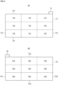
- FIG. 2 shows diagrams illustrating regions with high current densities and regions with low current densities in a positive electrode current collector and a negative electrode current collector when a voltage is applied to the electrode assembly of FIG. 1 .
- the positive electrode current collector may be equally divided into six regions. Among the six regions, a region 11A with a high current density may be a region in which the positive electrode tab is formed, and regions 11B with a low current density may be the remaining regions excluding the region with a high current density of the positive electrode current collector.
- the negative electrode current collector may be equally divided into six regions. Among the six regions, a region with a high current density may be a region in which the negative electrode tab is formed, and the regions with a low current density may be the remaining regions excluding the region with a high current density of the negative electrode current collector.
- a surface on which the negative electrode tab is formed is one surface 21a of the negative electrode current collector, a surface opposite to the one surface 21a of the negative electrode current collector is the other surface 21b, and surfaces connecting the one surface 21a and the other surface 21b are a first side surface 21c and a second surface 21d.
- the one surface (or the other surface) may be equally divided into three regions, the first side surface (or the second side surface) may be equally divided into two regions, and thus six regions 21A and 21B may be obtained.
- a region in which the negative electrode tab is formed may be the region 21A with a high current density.
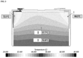
- FIG. 3 is an exemplary diagram illustrating a temperature distribution when a voltage is applied to the electrode assembly of FIG. 1 .
- a temperature of a positive electrode tab region (II) was 66.5 °C and a temperature of a negative electrode tab region (I) was 72.1 °C, whereas a temperature of a bottom portion (IV) was 52.6 °C and a temperature of a central portion (III) was 57.7 °C, and thus a temperature gradient occurred.
- FIG. 4 is a conceptual diagram for describing a distribution of holes 1 in the regions 11A and 21A with a high current density in FIG. 2 .
- FIG. 5 is a conceptual diagram for describing a distribution of holes 2 in the regions 11B and 21B with a low current density in FIG. 2 .
- a gap distance between the holes in the region with a high current density may be narrower than that in the region with a low current density.
- the gap distance between the holes may become small toward the positive electrode tab or the negative electrode tab.
- the gap distance between the holes in the region with a high current density may be the same or different and may be 50 ⁇ m or less, for example, 10 ⁇ m to 40 ⁇ m. In one specific example, the gap distance between the holes in the region with a low current density may be the same or different and may be 100 ⁇ m or less, for example, 100 ⁇ m to 500 ⁇ m.
- the "gap distance" means a gap distance between on hole and the nearest hole for the one hole.
- FIG. 6 is a conceptual diagram of an electrode assembly for a lithium secondary battery according to another embodiment.
- the positive electrode current collector may be equally divided into nine regions. Among the nine regions, a region with a high current density may be a region in which the positive electrode tab is formed, and regions with a low current density may be the remaining regions excluding the region with a high current density of the positive electrode current collector.
- the negative electrode current collector may be equally divided into nine regions. Among the nine regions, a region with a high current density may be a region in which the negative electrode tab is formed, and regions with a low current density may be the remaining regions excluding the region with a high current density of the negative electrode current collector.
- a surface on which the positive electrode tab 13 is formed is one surface 11a of the positive electrode current collector 11, a surface opposite to the one surface 11a of the positive electrode current collector 11 is the other surface 11b, and surfaces connecting the one surface 11a and the other surface 11b are a first side surface 11c and a second surface 11d.
- the one surface (or the other surface) may be equally divided into three regions, the first side surface (or the second side surface) may be equally divided into three regions, and thus nine regions 11A and 11B may be obtained.
- a region 11A in which the positive electrode tab is formed may be the region with a high current density.
- a surface on which the negative electrode tab 23 is formed is one surface 21a of the negative electrode current collector 21, a surface opposite to the one surface 21a of the positive electrode current collector 21 is the other surface 21b, and surfaces connecting the one surface 21a and the other surface 21b are a first side surface 21c and a second surface 21d.
- the one surface (or the other surface) may be equally divided into three regions, the first side surface (or the second side surface) may be equally divided into three regions, and thus nine regions 21A and 21B may be obtained.
- the region 2 1A in which the positive electrode tab is formed may be the region with a high current density.
- FIG. 7 is a conceptual diagram of an electrode assembly for a lithium secondary battery according to still another embodiment.
- the positive electrode current collector may be equally divided into four regions. Among the four regions, a region with a high current density may be a region in which the positive electrode tab is formed, and regions with a low current density may be the remaining regions excluding the region with a high current density of the positive electrode current collector.
- the negative electrode current collector may be equally divided into four regions. Among the four regions, a region with a high current density may be a region in which the negative electrode tab is formed, and regions with a low current density may be the remaining regions excluding the region with a high current density of the negative electrode current collector.
- a surface on which the positive electrode tab 13 is formed is one surface 11a of the positive electrode current collector 11, a surface opposite to the one surface 11a of the positive electrode current collector 11 is the other surface 11b, and surfaces connecting the one surface 11a and the other surface 11b are a first side surface 11c and a second surface 11d.
- the one surface (or the other surface) may be equally divided into two regions, the first side surface (or the second side surface) may be equally divided into two regions, and thus four regions 11A and 11B may be obtained.
- a region 11A in which the positive electrode tab is formed may be the region with a high current density.
- the positive electrode active material layer includes a positive electrode active material and may further include a binder and/or a conductive material.
- An alloy of lithium and a metal selected from Na, K, Rb, Cs, Fr, Be, Mg, Ca, Sr, Si, Sb, Pb, In, Zn, Ba, Ra, Ge, Al and Sn may be used as the alloy of lithium metal.
- the silicon-carbon composite may be a composite of silicon and amorphous carbon.
- the silicon-carbon composite may be in the form of silicon particles and amorphous carbon applied on surfaces of the silicon particles.
- the silicon-carbon composite may include a secondary particle (core) in which silicon primary particles are combined and an amorphous carbon coating layer (shell) positioned on a surface of the secondary particle.
- the amorphous carbon may also be positioned between the silicon primary particles and, for example, the silicon primary particles may be coated with amorphous carbon.
- the secondary particles may be present by being dispersed in an amorphous carbon matrix.
- the silicon-carbon composite may further include crystalline carbon.
- the silicon-carbon composite may include a core containing crystalline carbon and silicon particles and an amorphous carbon coating layer positioned on a surface of the core.
- the Si-based negative electrode active material or the Sn-based negative electrode active material may be used by being mixed with a carbon-based negative electrode active material.
- the binder serves to adhere negative electrode active material particles to each other and also to adhere the negative electrode active material to a current collector.
- a non-aqueous binder, an aqueous binder, a dry binder, or a combination thereof may be used as the binder.
- non-aqueous binder may include polyvinyl chloride, carboxylated polyvinyl chloride, polyvinyl fluoride, ethylene propylene copolymer, polystyrene, polyurethane, polytetrafluoroethylene, polyvinylidene fluoride, polyethylene, polypropylene, polyamideimide, polyimide, and a combination thereof.
- the aqueous binder may be one selected from styrene-butadiene rubber, (meth)acrylated styrene-butadiene rubber, (meth)acrylonitrile-butadiene rubber, (meth)acrylic rubber, butyl rubber, fluorine rubber, polyethylene oxide, polyvinylpyrrolidone, polyepichlorohydrin, polyphosphazene, Poly(meth)acrylonitrile, ethylene propylene diene copolymer, polyvinylpyridine, chlorosulfonated polyethylene, latex, polyester resin, (meth)acrylic resin, phenol resin, epoxy resin, polyvinyl alcohol, and a combination thereof.
- a cellulose-based compound capable of imparting viscosity may be further included.
- One or more of carboxymethyl cellulose, hydroxypropylmethyl cellulose, methyl cellulose, or alkali metal salts thereof can be mixed and used as the cellulose-based compound. Na, K, or Li may be used as the alkali metal.
- the dry binder is a polymer material capable of being fiberized and may be, for example, polytetrafluoroethylene, polyvinylidene fluoride, polyvinylidene fluoride-hexafluoropropylene copolymer, polyethylene oxide, or a combination thereof.
- One selected from copper foil, nickel foil, stainless steel foil, titanium foil, nickel foam, copper foam, a polymer substrate coated with a conductive metal, and a combination thereof may be used as the negative electrode current collector.
- An electrolyte for a lithium secondary battery contains a non-aqueous organic solvent and lithium salt.
- the non-aqueous organic solvent may be a carbonate-based, ester-based, ether-based, ketone-based, or alcohol-based solvent, an aprotic solvent, or a combination thereof.
- Dimethyl carbonate (DMC), diethyl carbonate (DEC), dipropyl carbonate (DPC), methylpropyl carbonate (MPC), ethylpropyl carbonate (EPC), methylethyl carbonate (MEC), ethylene carbonate (EC), propylene carbonate (PC), or butylene carbonate (BC) may be used as the carbonate-based solvent.
- Methyl acetate, ethyl acetate, n-propyl acetate, dimethyl acetate, methyl propionate, ethyl propionate, decanolide, mevalonolactone, valerolactone, or caprolactone may be used as the ester-based solvent.
- Ethyl alcohol or isopropyl alcohol may be used as the alcohol-based solvent, and nitrile such as R-CN (R is a straight-chain, branched, or ring-structured hydrocarbon group having 2 to 20 carbon atoms and may include a double bond, an aromatic ring, or an ether group), amide such as dimethylformamide, dioxolanes such as 1,3-dioxolane and 1,4-dioxolane, or sulfolane may be used as the aprotic solvent.
- R-CN R is a straight-chain, branched, or ring-structured hydrocarbon group having 2 to 20 carbon atoms and may include a double bond, an aromatic ring, or an ether group
- amide such as dimethylformamide
- dioxolanes such as 1,3-dioxolane and 1,4-dioxolane
- sulfolane may be used as the aprotic solvent.
- the non-aqueous organic solvents may be used alone or in combination of two or more thereof.
- cyclic carbonate and chain carbonate may be mixed and used, and the cyclic carbonate and the chain carbonate may be mixed at a volume ratio of 1:1 to 1:9.
- the lithium salt is a material that is dissolved in an organic solvent and acts as a source of lithium ions in the battery to enable a basic operation of a lithium secondary battery and tp promote movement of lithium ions between the positive electrode and the negative electrode.
- Representative examples of the lithium salt may include one or two or more selected from LiPF 6 , LiBF 4 , LiSbF 6 , LiAsF 6 , LiClO 4 , LiAlO 2 , LiAlCl 4 , LiPO 2 F 2 , LiCl, LiI, LiN(SO 3 C 2 F 5 ) 2 , Li(FSO 2 ) 2 N (lithium bis(fluorosulfonyl)imide (LiFSI)), LiC 4 F 9 SO 3 , LiN(C x F 2x+1 SO 2 )(C y F 2y+1 SO 2 ) (x and y are integers from 1 to 20), lithium trifluoromethane sulfonate, lithium tetrafluoroethan
- a separator may be present between the positive electrode and the negative electrode depending on a type of lithium secondary battery.
- Polyethylene, polypropylene, polyvinylidene fluoride, or a multilayer membrane of two or more layers thereof may be used as the separator.
- mixed multilayer membranes such as a polyethylene/polypropylene two-layer separator, a polyethylene/polypropylene/polyethylene three-layer separator, and a polypropylene/polyethylene/polypropylene three-layer separator may be used.
- the separator may include a porous base material and a coating layer containing an organic material, an inorganic material, or a combination thereof positioned on one or both surfaces of the porous base material.
- the porous base material may be any one polymer selected from polyolefin such as polyethylene and polypropylene, polyester such as polyethylene terephthalate and polybutylene terephthalate, polyacetal, polyamide, polyimide, polycarbonate, polyether ketone, polyaryl ether ketone, polyetherimide, polyamideimide, polybenzimidazole, polyethersulfone, polyphenylene oxide, cyclic olefin copolymer, polyphenylene sulfide, polyethylene naphthalate, glass fiber, Teflon, and polytetrafluoroethylene, or a polymer membrane formed from a copolymer or mixture of two or more thereof.
- polyolefin such as polyethylene and polypropylene
- polyester such as polyethylene terephthalate and polybutylene terephthalate
- polyacetal polyamide, polyimide, polycarbonate, polyether ketone, polyaryl ether ketone, polyetherimide,
- the organic material may include a polyvinylidene fluoride-based polymer or a (meth)acrylic-based polymer.
- the inorganic material may include an inorganic particle selected from Al 2 O 3 , SiO 2 , TiO 2 , SnO 2 , CeO 2 , MgO, NiO, CaO, GaO, ZnO, ZrO 2 , Y 2 O 3 , SrTiO 3 , BaTiO 3 , Mg(OH) 2 , boehmite, and a combination thereof, but the present invention is not limited thereto.
- an electrode included in the electrode assembly for a lithium secondary battery is provided.
- a lithium secondary battery including the electrode assembly for a lithium secondary battery is provided.
- the lithium secondary battery may be classified into a cylindrical battery, a prismatic battery, a pouch battery, and a coin battery according to a battery shape.
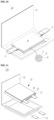
- FIGS. 8 to 11 are schematic diagrams illustrating lithium secondary batteries according to one embodiment, FIG. 8 shows a cylindrical battery, FIG. 9 shows a prismatic - battery, and FIGS. 10 and 11 show a pouch battery.
- a lithium secondary battery 100 may include an electrode assembly 40 with a separator 30 interposed between a positive electrode 10 and a negative electrode 20, and a case 50 in which the electrode assembly 40 is embedded.
- the positive electrode 10, the negative electrode 20, and the separator 30 may be impregnated with an electrolyte (not shown). As shown in FIG.
- the lithium secondary battery 100 may include a sealing member 60 for sealing the case 50.
- the lithium secondary battery 100 may include a positive electrode lead tab 11, a positive electrode terminal 12, a negative electrode lead tab 21, and a negative electrode terminal 22.
- the lithium secondary battery 100 may include an electrode tab 70, that is, a positive electrode tab 71 and a negative electrode tab 72, which serves as an electrical passage for guiding a current formed in the electrode assembly 40 to the outside.
- the lithium secondary battery according to one embodiment of the present invention can be applied to vehicles, mobile phones, and/or various types of electrical devices, and the present invention is not limited thereto.
- a plurality of holes were formed in aluminum foil (with a thickness of 20 ⁇ m) using a punching method.
- a cross section of the hole had a circular shape.
- a hole area ratio in a region in which a tab was expected to be attached to the aluminum foil was 30%, and a diameter of the hole was 300 ⁇ m or less.
- a hole area ratio in the remaining region, excluding the above region, was 5%, and a diameter of the hole was 300 ⁇ m or less. In this case, the diameter of the hole in the region in which the tab was expected to be attached was smaller than the diameter of the hole in the remaining region excluding the above region.
- a plurality of holes were formed in copper foil (with a thickness of 20 ⁇ m) using a punching method.
- the holes had the same diameter of 250 ⁇ m, and a cross section of the hole had a circular shape.
- a hole area ratio in a region in which a tab was expected to be attached to the copper foil was 30%, and a diameter of the hole was 300 ⁇ m or less.
- a hole area ratio in the remaining region, excluding the above region, was 5%, and a diameter of the hole was 300 ⁇ m or less. In this case, the diameter of the hole in the region in which the tab was expected to be attached was smaller than the diameter of the hole in the remaining region excluding the above region.
- a lithium secondary battery was manufactured in the same manner as in Example 1 using the manufactured current collector.
- a current density was evaluated relative to a temperature distribution when a voltage of 4.5 V was applied to the manufactured battery.
- a current density ratio of a region in which a hole area ratio was 30% of the positive electrode current collector to a region in which a hole area ratio was 5% of the positive electrode current collector was 2: 1.
- a current density ratio of a region in which a hole area ratio was 40% of the negative electrode current collector to a region in which a hole area ratio was 5% of the negative electrode current collector was 2: 1. According to Example 1, the current density ratio is low so that degradation of the electrode plate can be suppressed, a battery capacity can be increased, and a battery lifetime can be improved.
- a plurality of holes were formed in aluminum foil (with a thickness of 20 ⁇ m) using a punching method.
- the holes had the same diameter of 250 ⁇ m, and a cross section of the hole had a circular shape.
- the positive electrode current collector of FIG. 2A was manufactured by adjusting a hole area ratio in a region in which a tab was expected to be attached to the aluminum foil to 30% and hole area ratios in the remaining regions, excluding the region in which the tab was expected to be attached to the aluminum foil, to 60%.
- a lithium secondary battery was manufactured in the same manner as in Example 1 using the manufactured current collector.
Landscapes
- Chemical & Material Sciences (AREA)
- Chemical Kinetics & Catalysis (AREA)
- Electrochemistry (AREA)
- General Chemical & Material Sciences (AREA)
- Engineering & Computer Science (AREA)
- Manufacturing & Machinery (AREA)
- Materials Engineering (AREA)
- Battery Electrode And Active Subsutance (AREA)
- Connection Of Batteries Or Terminals (AREA)
Applications Claiming Priority (1)
| Application Number | Priority Date | Filing Date | Title |
|---|---|---|---|
| KR1020230192250A KR20250101034A (ko) | 2023-12-27 | 2023-12-27 | 리튬 이차 전지용 전극의 조립체, 이에 포함되는 전극 및 이를 포함하는 리튬 이차 전지 |
Publications (1)
| Publication Number | Publication Date |
|---|---|
| EP4579822A1 true EP4579822A1 (de) | 2025-07-02 |
Family
ID=94128829
Family Applications (1)
| Application Number | Title | Priority Date | Filing Date |
|---|---|---|---|
| EP24223373.2A Pending EP4579822A1 (de) | 2023-12-27 | 2024-12-27 | Elektrodenanordnung für eine wiederaufladbare lithiumbatterie, darin enthaltene elektrode und wiederaufladbare lithiumbatterie mit der elektrodenanordnung |
Country Status (3)
| Country | Link |
|---|---|
| EP (1) | EP4579822A1 (de) |
| KR (1) | KR20250101034A (de) |
| CN (1) | CN120221802A (de) |
Citations (4)
| Publication number | Priority date | Publication date | Assignee | Title |
|---|---|---|---|---|
| EP1045466A1 (de) * | 1999-04-16 | 2000-10-18 | Samsung SDI Co., Ltd. | Stromkollektor, Elektrode und diesen Stromkollektor enthaltende Sekundärbatterie |
| US20030104281A1 (en) * | 2001-11-28 | 2003-06-05 | Dominick Frustaci | Electrochemical cell current collector having openings of progressively larger sizes converging at a tab |
| US20120214059A1 (en) * | 2010-09-10 | 2012-08-23 | Robert Bosch Gmbh | Collection structure in batteries |
| EP3989326A1 (de) * | 2020-05-14 | 2022-04-27 | LG Energy Solution, Ltd. | Elektrodenanordnung mit erhöhter sicherheit und lithiumsekundärbatterie damit |
-
2023
- 2023-12-27 KR KR1020230192250A patent/KR20250101034A/ko active Pending
-
2024
- 2024-12-27 EP EP24223373.2A patent/EP4579822A1/de active Pending
- 2024-12-27 CN CN202411951646.8A patent/CN120221802A/zh active Pending
Patent Citations (4)
| Publication number | Priority date | Publication date | Assignee | Title |
|---|---|---|---|---|
| EP1045466A1 (de) * | 1999-04-16 | 2000-10-18 | Samsung SDI Co., Ltd. | Stromkollektor, Elektrode und diesen Stromkollektor enthaltende Sekundärbatterie |
| US20030104281A1 (en) * | 2001-11-28 | 2003-06-05 | Dominick Frustaci | Electrochemical cell current collector having openings of progressively larger sizes converging at a tab |
| US20120214059A1 (en) * | 2010-09-10 | 2012-08-23 | Robert Bosch Gmbh | Collection structure in batteries |
| EP3989326A1 (de) * | 2020-05-14 | 2022-04-27 | LG Energy Solution, Ltd. | Elektrodenanordnung mit erhöhter sicherheit und lithiumsekundärbatterie damit |
Also Published As
| Publication number | Publication date |
|---|---|
| CN120221802A (zh) | 2025-06-27 |
| KR20250101034A (ko) | 2025-07-04 |
Similar Documents
| Publication | Publication Date | Title |
|---|---|---|
| EP4579822A1 (de) | Elektrodenanordnung für eine wiederaufladbare lithiumbatterie, darin enthaltene elektrode und wiederaufladbare lithiumbatterie mit der elektrodenanordnung | |
| EP4704244A1 (de) | Elektrodenanordnung und sekundärbatterie | |
| US20260066295A1 (en) | Negative electrode active material for rechargeable lithium battery and rechargeable lithium battery including the same | |
| US20260045482A1 (en) | Rechargeable lithium battery and method of fabricating the same | |
| US20250343235A1 (en) | Negative electrodes for rechargeable lithium batteries, and rechargeable lithium batteries including same | |
| US20260074324A1 (en) | Composite substrate for rechargeable lithium battery and rechargeable lithium battery including the same | |
| EP4700839A2 (de) | Elektroden für eine wiederaufladbare lithiumbatterie und wiederaufladbare lithiumbatterie damit | |
| EP4718510A1 (de) | Positive elektrode und wiederaufladbare lithiumbatterie damit | |
| US20250201848A1 (en) | Negative electrode for rechargeable lithium battery and rechargeable lithium battery including the same | |
| US20250174637A1 (en) | Negative electrode for rechargeable lithium battery and rechargeable lithium battery including same | |
| EP4629347A1 (de) | Positive elektrode mit niedrigem widerstand und wiederaufladbare lithiumbatterie damit | |
| US20250246624A1 (en) | Negative electrode for rechargeable lithium battery and rechargeable lithium battery including same | |
| US20260066492A1 (en) | Electrode for rechargeable lithium battery and rechargeable lithium battery including the same | |
| US20250246599A1 (en) | Negative electrode for rechargeable lithium battery and rechargeable lithium battery including same | |
| US20250293261A1 (en) | Composite substrate for rechargeable lithium battery and rechargeable lithium battery including the composite substrate | |
| US20250118750A1 (en) | Negative electrode for rechargeable lithium battery and rechargeable lithium battery including the same | |
| US20250372820A1 (en) | Separator for rechargeable lithium battery, method of manufacturing the same, and rechargeable lithium battery including the same | |
| US20250391869A1 (en) | Positive electrode for rechargeable lithium battery and rechargeable lithium battery comprising the same | |
| US20250038209A1 (en) | Electrode for rechargeable lithium battery and rechargeable lithium battery including the same | |
| US20250336982A1 (en) | Positive electrode for rechargeable lithium batteries and rechargeable lithium batteries containing the positive electrode | |
| US20250364542A1 (en) | Negative electrode active material, negative electrode including the negative electrode active material, rechargeable lithium battery including the negative electrode active material, and method of preparing the negative electrode active material | |
| US20260066300A1 (en) | Positive electrode and rechargeable lithium battery including the same | |
| US20250125359A1 (en) | Negative active material for rechargeable lithium battery, negative electrode including same, and rechargeable lithium battery including same | |
| EP4645487A1 (de) | Verbundsubstrat für eine wiederaufladbare lithiumbatterie und wiederaufladbare lithiumbatterie damit | |
| US20250336968A1 (en) | Positive electrode and rechargeable lithium battery including the positive electrode |
Legal Events
| Date | Code | Title | Description |
|---|---|---|---|
| PUAI | Public reference made under article 153(3) epc to a published international application that has entered the european phase |
Free format text: ORIGINAL CODE: 0009012 |
|
| STAA | Information on the status of an ep patent application or granted ep patent |
Free format text: STATUS: REQUEST FOR EXAMINATION WAS MADE |
|
| 17P | Request for examination filed |
Effective date: 20241227 |
|
| AK | Designated contracting states |
Kind code of ref document: A1 Designated state(s): AL AT BE BG CH CY CZ DE DK EE ES FI FR GB GR HR HU IE IS IT LI LT LU LV MC ME MK MT NL NO PL PT RO RS SE SI SK SM TR |