EP4579591A2 - Verfahren und system zur identifizierung pathologischer veränderungen in medizinischen nachfolgebildern - Google Patents
Verfahren und system zur identifizierung pathologischer veränderungen in medizinischen nachfolgebildern Download PDFInfo
- Publication number
- EP4579591A2 EP4579591A2 EP25175886.8A EP25175886A EP4579591A2 EP 4579591 A2 EP4579591 A2 EP 4579591A2 EP 25175886 A EP25175886 A EP 25175886A EP 4579591 A2 EP4579591 A2 EP 4579591A2
- Authority
- EP
- European Patent Office
- Prior art keywords
- image data
- follow
- pathological changes
- image
- reference image
- Prior art date
- Legal status (The legal status is an assumption and is not a legal conclusion. Google has not performed a legal analysis and makes no representation as to the accuracy of the status listed.)
- Pending
Links
Images
Classifications
-
- G—PHYSICS
- G06—COMPUTING OR CALCULATING; COUNTING
- G06T—IMAGE DATA PROCESSING OR GENERATION, IN GENERAL
- G06T7/00—Image analysis
- G06T7/0002—Inspection of images, e.g. flaw detection
- G06T7/0012—Biomedical image inspection
- G06T7/0014—Biomedical image inspection using an image reference approach
- G06T7/0016—Biomedical image inspection using an image reference approach involving temporal comparison
-
- G—PHYSICS
- G16—INFORMATION AND COMMUNICATION TECHNOLOGY [ICT] SPECIALLY ADAPTED FOR SPECIFIC APPLICATION FIELDS
- G16H—HEALTHCARE INFORMATICS, i.e. INFORMATION AND COMMUNICATION TECHNOLOGY [ICT] SPECIALLY ADAPTED FOR THE HANDLING OR PROCESSING OF MEDICAL OR HEALTHCARE DATA
- G16H50/00—ICT specially adapted for medical diagnosis, medical simulation or medical data mining; ICT specially adapted for detecting, monitoring or modelling epidemics or pandemics
- G16H50/20—ICT specially adapted for medical diagnosis, medical simulation or medical data mining; ICT specially adapted for detecting, monitoring or modelling epidemics or pandemics for computer-aided diagnosis, e.g. based on medical expert systems
-
- G—PHYSICS
- G06—COMPUTING OR CALCULATING; COUNTING
- G06N—COMPUTING ARRANGEMENTS BASED ON SPECIFIC COMPUTATIONAL MODELS
- G06N3/00—Computing arrangements based on biological models
- G06N3/02—Neural networks
- G06N3/04—Architecture, e.g. interconnection topology
- G06N3/045—Combinations of networks
-
- G—PHYSICS
- G06—COMPUTING OR CALCULATING; COUNTING
- G06N—COMPUTING ARRANGEMENTS BASED ON SPECIFIC COMPUTATIONAL MODELS
- G06N3/00—Computing arrangements based on biological models
- G06N3/02—Neural networks
- G06N3/04—Architecture, e.g. interconnection topology
- G06N3/0464—Convolutional networks [CNN, ConvNet]
-
- G—PHYSICS
- G06—COMPUTING OR CALCULATING; COUNTING
- G06N—COMPUTING ARRANGEMENTS BASED ON SPECIFIC COMPUTATIONAL MODELS
- G06N3/00—Computing arrangements based on biological models
- G06N3/02—Neural networks
- G06N3/08—Learning methods
-
- G—PHYSICS
- G06—COMPUTING OR CALCULATING; COUNTING
- G06N—COMPUTING ARRANGEMENTS BASED ON SPECIFIC COMPUTATIONAL MODELS
- G06N3/00—Computing arrangements based on biological models
- G06N3/02—Neural networks
- G06N3/08—Learning methods
- G06N3/09—Supervised learning
-
- G—PHYSICS
- G06—COMPUTING OR CALCULATING; COUNTING
- G06T—IMAGE DATA PROCESSING OR GENERATION, IN GENERAL
- G06T7/00—Image analysis
- G06T7/0002—Inspection of images, e.g. flaw detection
- G06T7/0012—Biomedical image inspection
-
- G—PHYSICS
- G06—COMPUTING OR CALCULATING; COUNTING
- G06T—IMAGE DATA PROCESSING OR GENERATION, IN GENERAL
- G06T7/00—Image analysis
- G06T7/30—Determination of transform parameters for the alignment of images, i.e. image registration
- G06T7/38—Registration of image sequences
-
- G—PHYSICS
- G16—INFORMATION AND COMMUNICATION TECHNOLOGY [ICT] SPECIALLY ADAPTED FOR SPECIFIC APPLICATION FIELDS
- G16H—HEALTHCARE INFORMATICS, i.e. INFORMATION AND COMMUNICATION TECHNOLOGY [ICT] SPECIALLY ADAPTED FOR THE HANDLING OR PROCESSING OF MEDICAL OR HEALTHCARE DATA
- G16H30/00—ICT specially adapted for the handling or processing of medical images
- G16H30/20—ICT specially adapted for the handling or processing of medical images for handling medical images, e.g. DICOM, HL7 or PACS
-
- G—PHYSICS
- G06—COMPUTING OR CALCULATING; COUNTING
- G06T—IMAGE DATA PROCESSING OR GENERATION, IN GENERAL
- G06T2207/00—Indexing scheme for image analysis or image enhancement
- G06T2207/10—Image acquisition modality
- G06T2207/10072—Tomographic images
- G06T2207/10081—Computed x-ray tomography [CT]
-
- G—PHYSICS
- G06—COMPUTING OR CALCULATING; COUNTING
- G06T—IMAGE DATA PROCESSING OR GENERATION, IN GENERAL
- G06T2207/00—Indexing scheme for image analysis or image enhancement
- G06T2207/10—Image acquisition modality
- G06T2207/10072—Tomographic images
- G06T2207/10088—Magnetic resonance imaging [MRI]
-
- G—PHYSICS
- G06—COMPUTING OR CALCULATING; COUNTING
- G06T—IMAGE DATA PROCESSING OR GENERATION, IN GENERAL
- G06T2207/00—Indexing scheme for image analysis or image enhancement
- G06T2207/10—Image acquisition modality
- G06T2207/10072—Tomographic images
- G06T2207/10104—Positron emission tomography [PET]
-
- G—PHYSICS
- G06—COMPUTING OR CALCULATING; COUNTING
- G06T—IMAGE DATA PROCESSING OR GENERATION, IN GENERAL
- G06T2207/00—Indexing scheme for image analysis or image enhancement
- G06T2207/10—Image acquisition modality
- G06T2207/10116—X-ray image
-
- G—PHYSICS
- G06—COMPUTING OR CALCULATING; COUNTING
- G06T—IMAGE DATA PROCESSING OR GENERATION, IN GENERAL
- G06T2207/00—Indexing scheme for image analysis or image enhancement
- G06T2207/20—Special algorithmic details
- G06T2207/20081—Training; Learning
-
- G—PHYSICS
- G06—COMPUTING OR CALCULATING; COUNTING
- G06T—IMAGE DATA PROCESSING OR GENERATION, IN GENERAL
- G06T2207/00—Indexing scheme for image analysis or image enhancement
- G06T2207/20—Special algorithmic details
- G06T2207/20084—Artificial neural networks [ANN]
-
- G—PHYSICS
- G06—COMPUTING OR CALCULATING; COUNTING
- G06T—IMAGE DATA PROCESSING OR GENERATION, IN GENERAL
- G06T2207/00—Indexing scheme for image analysis or image enhancement
- G06T2207/20—Special algorithmic details
- G06T2207/20212—Image combination
- G06T2207/20224—Image subtraction
-
- G—PHYSICS
- G06—COMPUTING OR CALCULATING; COUNTING
- G06T—IMAGE DATA PROCESSING OR GENERATION, IN GENERAL
- G06T2207/00—Indexing scheme for image analysis or image enhancement
- G06T2207/30—Subject of image; Context of image processing
- G06T2207/30004—Biomedical image processing
- G06T2207/30061—Lung
-
- G—PHYSICS
- G06—COMPUTING OR CALCULATING; COUNTING
- G06T—IMAGE DATA PROCESSING OR GENERATION, IN GENERAL
- G06T2207/00—Indexing scheme for image analysis or image enhancement
- G06T2207/30—Subject of image; Context of image processing
- G06T2207/30004—Biomedical image processing
- G06T2207/30068—Mammography; Breast
Definitions
- the present embodiments relate to medical image processing, such as image processing for computed tomography images or magnetic resonance images.
- Automated image processing for follow up reading and longitudinal change assessment is an important task in medical imaging techniques such as computed tomography (CT) or magnetic resonance imaging (MRI).
- CT computed tomography
- MRI magnetic resonance imaging
- the task of recognizing changes in medical images is a technical problem due to the challenge of distinguishing pathological from normal changes in the medical images. For example, for a follow up scan of a lung or other organ of a patient, normal anatomic changes such as respiration or other anatomical differences may mask pathological changes such as cancerous nodule growth or shrinkage.
- Reference and follow-up medical images may relate to two-dimensional data sets providing two dimensions in space. Further, reference and follow-up medical images may relate to three-dimensional data sets providing three dimensions in space.
- the reference and follow-up medical image data depict a body part of a patient in the sense that they contain a two- or three-dimensional image data of the patient's body part (i.e., follow-up and reference image generally show the same body part of the same patient).
- Reference and follow-up medical image data may, for example, be in the form of an array of pixels or voxels. Such arrays of pixels or voxels may be representative of intensity, absorption or other parameter as a function of three-dimensional position, and may, for example, be obtained by suitable processing of measurement signals obtained by a medical imaging modality.
- reference and follow-up image data relate to images acquired at different times, there will be changes visible from the reference image data to the follow-up image data.
- two types of changes can be defined.
- One type of changes are the anatomical changes or deformations. These changes relate to normal or "healthy" changes.
- One example for such anatomical deformations relates to the breathing motion of lung tissue. As a patient inhales or exhales, the shape of the lung changes. Thereby, the lower portions of the lungs may exhibit larger deformations than, for example, the center of the lung. As the lung deforms, neighboring tissue will likewise undergo anatomical deformations.
- the method essentially foresees to a apply a two-steps approach.
- deformation fields indicative of the anatomical deformations are calculated using one or more image registrations.
- these deformation fields will in most cases contain artefacts mainly stemming from inaccurate image registrations and boundary effects.
- the outcome of the image registration i.e., all deformation fields and motion models used during image registration and so forth
- the underlying image data i.e., follow-up image data and/or reference image data
- the step of generating (or, in other words calculating) a deformation field by using one or more image registrations may thus be seen as a first estimate about the anatomical changes.
- this may include applying a plurality of image registrations, e.g., a designated image registration for each anatomy identified in the depicted patient's body part.
- Image registration as such is a well-known method in the art. Essentially, this includes registering an image with a corresponding image of a time series and finding a deformation field between the two images that determines a relationship between the coordinate systems of the reference image data and the follow-up image data such that each anatomical location in the reference image data is mapped to the same anatomical location in the follow-up image data.
- the deformation field may comprise a plurality of individual displacement vectors respectively associated with the voxels of reference image data and follow-up image data.
- a rigid registration in this context may comprise a registration in which the coordinates of data points in one data set are subject to rotation and translation in order to register the data set to another data set.
- An affine registration in this context may comprise a registration in which the coordinates of data points in one dataset are subject to rotation, translation, scaling and/or shearing in order to register the dataset to another dataset.
- a rigid registration may be considered to be a particular type of affine registration.
- Non-rigid registrations can provide different displacements for each voxel of the data set to be registered and can, for example, use non-linear transformations, in which the coordinates of data points in one dataset are subject to flexible deformations in order to register the data set to another data set.
- Non-linear transformations may in some cases be defined using vector fields such as warp fields, or other fields or functions, defining an individual displacement for each voxel in a three-dimensional data set.
- image registration reference is made to US 2011 / 0 081 066 and US 2012 / 0 235 679 , the contents of which are included in this application by reference.
- the one or more image registrations used according to the first aspect may be rigid image registrations, non-rigid image registrations and combinations thereof.
- the deformation fields are used to align the reference image data with the follow-up image data.
- the alignment is used to identify pathological differences between the two data sets.
- the aligning may include applying the deformation fields to the reference image data to generate a deformed prior image or deformed reference image data as the co-aligned image data. Further, the step of aligning may include applying the deformation field (as inverse deformation field) to the follow-up image data to generate deformed follow-up image data.
- the co-aligned image data may also relate to data where the follow-up image data and/or reference image data are registered with the deformation field, e.g., so that a displacement is assigned to each pixel or voxel of follow-up image data and/or reference image data.
- the co-aligned image data thus relates the calculated deformation field(s) to the visual information contained in the follow-up image data and/or reference image data.
- the co-aligned reference image may be conceived as constituting filtered image data in which the anatomical deformations have been filtered out.
- the estimate of the anatomical changes will comprise artefacts in the form of faults, unphysical distortions and inaccuracies, however.
- the co-aligned image data is provided to the machine learned network.
- the co-aligned image data comprises information about the deformation field and part or all of the image content information that was used to generate the deformation field in the first place.
- the machine learned network is trained to use this information and identify pathological changes between the follow-up image data and the reference image data. To do so, it may be trained to recognize artefacts in the deformation fields (i.e., artefacts stemming from the step of generating) by comparing it to the underlying image data.
- the training of the neural network may make use of the fact that artefacts in the deformation field are still present after the images have been aligned and that these can be readily related to the underlying image data.
- artefacts in the deformation field may readily be recognized as such when compared to the underlying image data.
- the machine learned network may check if distortions or singularities in the deformation field(s) fall onto boundaries visible between organs or anatomies as this might indicate that irregularities in the deformation stem from artefacts in the image registration.
- the machine learned network may be trained to recognize pathological changes (or, in other words, disease patterns) characterized by visual image features.
- the machine learned network may flag deformations as relating to pathological changes when they occur within an otherwise homogenous image segment, for instance.
- the machine learned network is a machine learned (artificial) neural network, most preferably a convolutional neural network.
- a neural network is basically built up like a biological neural net, e.g., a human brain.
- an artificial neural network comprises an input layer and an output layer. It may further comprise a plurality of layers between input and output layer. Each layer comprises at least one, preferably a plurality of nodes. Each node may be understood as a biological processing unit, e.g., a neuron. In other words, each neuron corresponds to an operation applied to input data.
- Nodes of one layer may be interconnected by edges or connections to nodes of other layers, in particular, by directed edges or connections. These edges or connections define the data flow between the nodes of the network.
- edges or connections are equipped with a parameter, wherein the parameter is often denoted as "weight".
- This parameter can regulate the importance of the output of a first node to the input of a second node, wherein the first node and the second node are connected by an edge.
- a neural network can be trained. In particular, training of a neural network is performed based on known pairs of input and output values according to a 'supervised learning' technique, wherein the known input values are used as inputs of the neural network, and wherein the corresponding output value of the neural network is compared to the corresponding known output value.
- the artificial neural network independently learns and adapts the weights for the individual nodes as long as the output values of the last network layer sufficiently correspond to the known output values according to the trainings data.
- this technique is also called 'deep learning'.
- the terms 'neural network' and 'artificial neural network' can be used as synonyms.
- a first group of neural network layers may be applied to extract features from images.
- image data such as the deformed reference image data or deformed follow-up image data, i.e., the gray scale and/or color values for each individual image element of the image, and/or serve as input values for the neural network.
- corresponding features may be extracted from the deformation field.
- the thus extracted features like, contrast, gradients, texture, density, distortion, singularities, gradients, or the like may be fed as input values to a second group of network layers also known as classifiers which serve to further assign objects and/or characteristics to at least one of the extracted features present in the image.
- classifiers also known as classifiers which serve to further assign objects and/or characteristics to at least one of the extracted features present in the image.
- both functions of the described neural network may likewise be carried out by separated, individual neural networks.
- image analysis for feature extraction can be carried out by a first neural network
- classification i.e., object and/or characteristic assignment can be carried out by a second neural
- the machine learned neural network may be a convolutional neural network.
- the machine learned neural network may be a deep convolutional neural network.
- a fully convolutional, image-to-image neural network may be used in which the co-aligned image data is input into the network, and the output is a filter image or a likelihood map of pathological changes. Any type of image-to-image neural network may be used.
- Alternative machine-learned networks may be used that are configured or trained to identify pathological changes if provided with deformation fields and corresponding medical image data.
- the inventors have recognized that, through the use of convolutional layers and/or deconvolutional layers, a neural network can be employed especially efficiently for image processing, since despite many connections between node layers, only a few edge weights (namely the edge weights corresponding to the values of the convolutional kernel) have to be determined by training. With a same number of training data, the accuracy of the neural network can thus also be improved.
- the method steps as introduced above synergistically contribute to a method that allows for a reliable identification of pathological changes in follow-up medical images.
- a method is provided that assists the user in providing a medical diagnosis by processing physiological measurements.
- the processing is essentially divided into two interlinked steps: the computation of one or more deformation fields with the help of appropriate image registrations and the subsequent analysis of the results using artificial intelligence.
- Basing the method on image registrations means that schemes and algorithms may be deployed which over the years have been thoroughly optimized for specific organs and anatomies and which have proven extremely powerful for specific tasks.
- Using image registrations has the further advantage that the starting point for the machine learned network is considerably improved which alleviates the training phase and improves the overall accuracy of the method.
- the implementation of a machine learned network makes it possible to readily verify and highlight the outcome of the method for the user.
- the usage of the machine learned model is the precondition to readily use image registrations across different anatomies and/or to combine a plurality of image registrations. This is because the learned ability of distinguishing relevant from irrelevant changes inherently comprises an error correction for artefacts which are inevitable when image registrations are applied to whole body parts comprising a multitude of anatomies and structures. For the user, this is of considerable help since medical diagnoses are generally not exclusively focused on one organ only but require screening neighboring organs and tissue for cancerous ingrowths and metastases.
- the method according to the first aspect is able to optimally support the user in providing a medical diagnosis.
- the reference image data is transformed into the "coordinate system" of the follow-up image data.
- the ensuing deformed reference image data is corrected for anatomic changes and deformations that happened in the period of time between acquisition of reference image data and follow-up image data.
- deformed reference image data and follow-up image data would in principle be already fit for a direct comparison to determine pathological changes between the two images.
- Such comparison might, for instance, comprise subtracting the deformed reference image data from the follow-up image data.
- the deformed reference image data is still based on straight-forward image registration, which is prone to contain artefacts, however, any pathological changes comprised in the result would be barely discernible from the artefacts, in practice.
- deformed reference image data constitutes an important intermediate result which has the twofold advantage that it can be readily processed by the machine learned network and provides a good basis for the ensuing presentation of the pathological changes to the user. Further, also in terms of training the machine learned model it constitutes a reasonable starting point, since deformed reference image data can be readily calculated for the available training data sets.
- the step of aligning may likewise comprise calculating deformed follow-up image data by applying the at least one deformation field to the reference image data.
- this step might be supplemented by a step of inverting the deformation field.
- the step of analyzing comprises generating an image filter corresponding to the co-aligned image data, the image filter being configured to highlight pathological changes based on the output of the machine learned network.
- the image filter may be configured such that it constitutes image data compatible with reference image data and follow-up image data.
- the image filter may have the same or similar format and/or dimensions as the reference image data and/or the follow-up image data.
- the image filter may be configured such that when applied to reference image data and/or follow-up image data, the pathological changes are highlighted.
- the image filter may be configured such that it can be overlaid over reference image data and/or follow-up image data, or that it can be multiplied with reference image data and/or follow-up image data.
- the machine learned network might be configured as image-to-image network with the co-aligned image data as input and the image filter as output.
- an output is provided which can be intuitively accessed by the user. It allows for a quick visual inspection of the pathological changes from one medical examination to the other.
- the subtraction of the deformed reference image data from the follow-up image data generates image data which has been corrected for motions and deformations as identified by image registration.
- This image data is subsequently also denoted as subtraction image data.
- the subtraction image data retains the pathological changes.
- the deformed reference image data also contains artefacts stemming from erroneous image registration.
- the subtraction image data is a two- or three-dimensional image in which pathological changes as well as artefacts may appear as non-zero entries (pixels or voxels).
- the subtraction image data is multiplied with the image filter.
- the image filter is configured so that it filters out artefacts in the subtraction image data.
- the image filter may contain zeros at places in the three-dimensional image data where artefacts have been identified.
- the image filter may be configured to highlight pathological changes.
- the image filter may contain enhancing factors at places in the two- or three-dimensional image data where pathological changes have been identified. Enhancing factors may be such that the intensity or brightness (e.g., in terms of the grey scale value) of the respective pixel or voxel is increased or that a color is changed or added to highlight the corresponding pixel or voxel against the background.
- the result of the above process i.e., subtracting the deformed reference image from the follow-up image and multiplying the result with the image filter
- the method further comprises labeling the pathological changes for a user on the basis of the metadata.
- an "artificial" pair of reference image data and follow-up image data is generated of which the artefacts are known, and which can be input to the machine learned network to see if all artefacts are correctly filtered out.
- the training effect may be further enhanced by configuring the model such that it can simulate "artificial" pathological changes when applied to medical image data.
- a further step is directed to aligning the training reference image data and the simulated follow-up image data using the one or more deformation fields to generate co-aligned image data, followed by analyzing the co-aligned image data to identify pathological changes in the body part from the training reference image data to the simulated follow-up image data using a machine learned network.
- a further step is directed to compare the result with the known input generated by the one or more models for biomechanical soft tissue deformation and adjusting weights in the neural network as a function of the comparison.
- a system for identifying pathological changes in follow-up medical images comprises an interface unit for receiving reference image data showing a body part of a patient at a first time and follow-up image data showing a body part of a patient at a subsequent second time.
- the system is adapted to implement the inventive method for identifying pathological changes in follow-up medical images.
- the computing unit may comprise an image registration unit configured to generate the one or more deformation fields using at least one image registration.
- the registration unit may further be configured to generate the one or more deformation fields additionally based on one or more biomechanical models of soft tissue deformation.
- the computing unit may further comprise an aligning unit configured to generate the co-aligned image data.
- the computing unit is further configured to run a machined learned network for analyzing the co-aligned image data for distinguishing pathological relevant changes from anatomical deformations and artefacts stemming from the generation of the one or more deformation fields.
- the computing unit may further comprise a visualization unit configured to generate a visualization (for a user) highlighting the identified pathological changes against anatomical deformations and any artefacts included in the co-aligned image data, e.g., in the form of the aforementioned change visualization image data.
- a visualization unit configured to generate a visualization (for a user) highlighting the identified pathological changes against anatomical deformations and any artefacts included in the co-aligned image data, e.g., in the form of the aforementioned change visualization image data.
- the computing unit may be realized as a data processing system or as a part of a data processing system.
- a data processing system can, for example, comprise a cloud-computing system, a computer network, a computer, a tablet computer, a smartphone and/or the like.
- the computing unit can comprise hardware and/or software.
- the hardware can comprise, for example, one or more processor, one or more memories and combinations thereof.
- the one or more memories may store instructions for carrying out the method steps according to the invention.
- the hardware can be configurable by the software and/or be operable by the software. Generally, all units, sub-units or modules may at least temporarily be in data exchange with each other, e.g., via a network connection or respective interfaces. Consequently, individual units may be located apart from each other.
- the interface unit may comprise an interface for data exchange with a local server or a central web server via internet connection for receiving the reference image data or follow-up image data.
- the interface unit may be further adapted to interface with one or more users of the system, e.g., by displaying the result of the processing by the computing unit to the user (e.g., in a graphical user interface) or by allowing the user to adjust parameters for image processing or visualization and/or to select the reference image data and follow-up image data.
- the invention further relates to a training system for training a machine learned network, comprising an interface, embodied for receiving the machine learned network, and further embodied for receiving training reference image data showing a body part of a patient.
- the training system further comprises a processor configured to generate simulated follow-up image data by deforming the training reference image data using one or more models for biomechanical soft tissue deformation and, optionally, including one or more simulated pathological changes (and, further optionally, artefacts in the deformation).
- the processor is further configured to calculate one or more deformation fields for the training reference image data and the simulated follow-up image data describing anatomical deformations in the body part between the training reference image data and the simulated follow-up image data.
- the processor is further configured to align the training reference image data and the simulated follow-up image data using the one or more deformation fields to generate co-aligned image data, and to analyze the co-aligned image data to identify pathological changes in the body part from the training reference image data to the simulated follow-up image data using a machine learned network.
- the processor is further configured to compare the result with the known input generated by the one or more models for biomechanical soft tissue deformation and adjusting the weights in the neural network as a function of the comparison.
- the invention further relates to an image analysis system comprising the system for identifying pathological changes in follow-up medical images and a medical image system configured to acquire, store and/or forward follow-up medical images (comprising the reference image data and the follow-up image data).
- the interface unit is configured to receive the reference image data and follow-up image data from the medical image system.
- the medical image system comprises one or more archive stations for storing reference image data RI and/or follow-up image data FI, which may be realized as a cloud storage or as a local or spread storage, e.g., as a PACS (Picture Archiving and Communication System).
- the medical image system may comprise one or more medical imaging modalities, such as a computed tomography system, a magnetic resonance system, an angiography (or C-arm X-ray) system, a positron-emission tomography system, a mammography system, system for acquiring digital pathology images or the like.
- the present invention is directed to a computer-readable medium on which program elements are stored that are readable and executable by a computing unit of a system for quantifying a medical image volume, in order to perform steps of the inventive method, when the program elements are executed by the computing unit.
- the realization of the invention by a computer program product and/or a computer-readable medium has the advantage that already existing providing systems can be easily adopted by software updates in order to work as proposed by the invention.
- the present invention provides a method and system relying on a machine learned network for identifying pathologically relevant changes in follow up medical image data.
- the machine learned network is trained to filter out irrelevant changes (e.g., by training it to detect artefacts) and/or to highlight relevant (also barely visible) pathological changes based on input data which already contain a first estimate about potentially relevant pathological changes.
- this input for the machine learned network is generated by combining organ-specific (non-rigid) image registrations and, optionally, motion model fitting for a whole-body part of a patient.
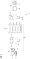
- Figure 1 depicts a system 1 for identifying pathological changes in follow up medical image data according to an embodiment of the present invention.
- System 1 is adapted to perform the method according to one or more embodiments, e.g., as further described with reference to Figures 2 or 4 .
- System 1 comprises a user interface 10 (as part of the interface unit) and a processing system 20 (as part of the computing unit). Further system 1 may comprise a medical image system 40 for acquiring, storing and/or forwarding reference image data RI and follow-up image data FI. Such image studies IS for follow-up-reading may be loaded from the medical image system 40, e.g., by the processing system 20 or by the user interface 10 directly.
- Reference image data RI and follow-up image data FI are three-dimensional medical image data sets acquired, for instance, using a computed tomography system or a magnetic resonance imaging system.
- the image information is encoded in a three-dimensional array of k times m times n voxels.
- reference image data RI and follow-up image data FI may relate to two-dimensional medical images, for instance acquired with a X-Ray facility, with the image information being encoded in m times n pixels.
- reference image data RI and follow-up image data FI show the same body part of a patient at different points in time.
- the follow-up image data FI relates to a follow-up examination at a later stage at a second time.
- the second time may be hours, days, week, months, or years after the first time. Further, there may be intervening scans or procedures between the first time and the second time.
- the follow-up image data FI is acquired using the same or similar settings and parameters as the reference image data RI. Similar settings and parameters may include, for example, the same medical imaging modality, a same dose (if available), the same phase timing, x-ray source voltage, contrast agent, MRI-protocol, among others.
- reference image data RI and follow-up image data FI will comprise various anatomies and organs.
- reference image data RI and follow-up image data FI might, for instance, depict the lung lobes, the rib cage, the heart, lymph nodes, and so forth.
- reference image data RI and/or follow-up image data FI relate to magnetic resonance (MR) image data of a patient (i.e., if they have been acquired using a magnetic resonance imaging system)
- reference image data RI and/or follow-up image data FI may have been acquired using different MR (pulse) sequences (i.e., reference image data RI has been acquired using a first MR sequence and follow-up image data FI has been acquired using a second MR sequence different than the first MR sequence).
- reference image data RI and follow-up image data FI may relate to different post-contrast sequences or follow-up image data FI may relate to a post-contrast sequence while the reference image data RI has been acquired before administering the contrast agent to the patient.
- Archive/review station 42 may further store further clinical information related to the reference image data RI and/or follow-up image data FI, wherein the clinical information may comprise, e.g., related medical findings, personal information related to the patient under consideration, patient records or the like.
- the clinical information may comprise, e.g., related medical findings, personal information related to the patient under consideration, patient records or the like.
- a further database (not shown) may store this related information.
- medical image system 40 may comprise a medical imaging modality 41, such as a computed tomography system, a magnetic resonance system, an angiography (or C-arm X-ray) system, a positron-emission tomography system, a mammography system, system for acquiring digital pathology images or the like.
- Medical image system 40 and, in particular, archive/review station 42 may likewise be activated on a request-base, wherein the request is sent by processing system 20 and/or user interface 10.
- Interface for data exchange may be realized as hardware- or software-interface, e.g., a PCI-bus, USB or fire-wire.
- Data transfer may be realized using a network connection.
- the network may be realized as local area network (LAN), e.g., an intranet or a wide area network (WAN).
- Network connection is preferably wireless, e.g., as wireless LAN (WLAN or Wi-Fi).
- the network may comprise a combination of different network examples.
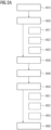
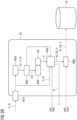
- Figure 2A depicts an inventive method for identifying pathological changes in follow-up medical images according to an embodiment of the present invention.
- Corresponding data streams are illustrated in Figure 2B .
- the method comprises several steps. The order of the steps does not necessarily correspond to the numbering of the steps but may also vary between different embodiments of the present invention. Optional steps are shown with dashed frames in Figure 2A .
- the reference image data RI and follow-up image data FI are provided (or received). This may involve selecting reference image data RI and follow-up image data FI from a plurality of follow-up images of a patient, e.g., stored in the medical image system 40. The selection may be performed manually by a user, e.g., by selecting appropriate image data in a graphical user interface running in the user interface 10. Moreover, the selection may be carried out automatically or semi-automatically by the system for users which need more assistance. In particular, this may involve automatically querying appropriate databases 42 for reference image data for a follow-up examination currently under review by the user at the user interface. Moreover, providing may involve merely receiving reference RI and follow-up image data FI.
- Step M10 may be performed at least partially either on user interface 10 or on processing system 20. Corresponding data exchange is included in this step where necessary.
- step M20 provides a comprehensive first estimate of the anatomical deformations in the whole-body part depicted in reference image data RI and follow-up image data FI.
- one or more deformation fields DF are calculated reflecting anatomic deformations between reference image data RI and follow-up image data FI.
- a deformation field DF can be conceived as an ensemble of deformation vectors indicative of the displacement of a voxel (or pixel) or group of voxels (pixels) from the reference image data RI to the follow-up image data FI.
- each voxel of the reference image data RI is assigned a deformation vector.
- the deformation field DF may be coarse-grained in the sense that groups of voxels (pixels) are combined and assigned a common deformation vector.
- the deformation fields DF are generated using image registration techniques and, in particular, non-rigid image registrations (sub-step M22).
- image registration techniques and, in particular, non-rigid image registrations (sub-step M22).
- non-rigid image registrations As all anatomies and organs comprised in the body part shall be appropriately addressed, it is preferred to rely on designated non-rigid image registration for individual organs and anatomies if available. If no designated non-rigid image registrations are available for certain structures of the body part, general non-rigid image registrations may be used.
- step M20 might as well comprise applying one uniform image registration only.
- the image registration in step M22 may be preceded by an optional sub-step M21 of segmenting reference image data RI and follow-up image data FI according to the anatomies and organs comprised in the depicted body part.
- Segmentation may comprise applying (in principle known) image segmentation procedures to identify and delineate organs and anatomies in reference image data RI and follow-up image data FI.
- a lung segmentation may be applied to identify lung lobes in reference image data RI and follow-up image data FI which facilitates the usage of image registrations specifically optimized for calculating anatomic deformations in lung tissue.
- Other anatomies shown in reference image data RI and follow-up image data FI may be treated similarly.
- the result of the image registration may be fitted to one or more motion models of soft tissue deformation in optional sub-step M23.
- each of the obtained deformation fields DF may be fitted separately.
- the overall displacement field as pieced together from the plurality of individual displacement fields may be fitted.
- the motion models may, for instance, be based on Navier-Cauchy equations for three-dimensional soft tissue deformation, the parameters of which are well known for certain types of tissue (e.g., from fitting the model to comparative image data or from separate experiments determining the visco-elastic properties of the underlying tissue).
- step M23 may bring about the benefit that certain artefacts in the displacement fields such as singularities, unphysical distortions or disruptions between the individual deformation fields DF are filtered out already at this stage.
- the motion models might be used for interpolating "blank spots" of the image volume for which no deformation fields DF could be generated with image registration.
- step M20 is performed in processing system 20.
- the deformed reference image data may be conceived as comparative data to the follow-up image data FI which comparative data has been corrected for the anatomic deformations between reference image data RI and follow-up image data FI as estimated in step M20. If the image registration in step M20 was 100 % accurate, subtracting the deformed reference image data from the follow-up image data FI would result in an image data set which only comprises pathological changes which occurred in the period of time between the reference image data RI and the follow-up image data FI were taken. As image registration for whole body parts comprising a plurality of anatomies and structures is usually far from being 100 % accurate, however, the subtraction image at this point will additionally comprise artefacts from improper image registrations. These are notoriously difficult to distinguish from pathological changes or, even worse, may mask pathological changes altogether.
- step M30 is performed in processing system 20.
- the co-aligned image data CAI is fed into the machine learned network 100 trained to identify the pathological changes for a user in ensuing step M40.
- "identifying” does not necessarily mean that the machine learned network 100 positively identifies the pathological changes.
- it is in principle enough to recognize the aforementioned artefacts in the co-aligned image data CAI and filter these out as the result would already highlight the pathological changes for the user against other anatomical changes and any artefacts.
- the versatility of the machine learned network 100 can be enhanced, however, if the machine learned network 100 has further been trained to also recognize pathological changes in the sense of positively identifying these in the co-aligned image data CAI.
- the output of the machine learned network 100 might be provided in the form of numerical values designating coordinates and, optionally, further parameters or metadata of the pathological changes (such as, for instance, growth rate, tissue penetration, pathology type, volume, cross-section, circumference, diameter, state of the contour, degree of calcification or fat deposition, degree of solidity, and so forth).
- the machine learned network 100 might be configured to output an image filter IF configured to filter out anatomical changes and artefacts in the deformation field DF and/or to visually enhance pathological changes in the co-aligned image data CAI.
- the image filter IF may be configured such that the anatomical changes and artefacts in the deformation field DF are filtered out and/or pathological changes are enhanced if applied to the aforementioned subtraction image data (generated by subtracting the deformed reference image data from the follow-up image data FI).
- the image filter IF may be considered as a weighted mask for bringing pathological changes to the attention of the user.
- the image filter will have the same or at least a similar format as the reference image data RI and follow-up image data FI.
- step M40 is performed in processing system 20.
- the results as provided by the machine learned network 100 are used to generate a visualization for the user.
- the visualization may comprise rendering one or more representation of the follow-up image data FI with the pathological changes highlighted for the user, e.g., as mentioned, by introducing symbols, applying color maps or heatmaps, and/or adjusting brightness or luminescence values.
- the result of the rendering can be in the form of one or more assistance images AI indicating to the user where the pathological changes are and/or what magnitude they have.
- the rendering may be a two-dimensional rendering on the basis of an appropriate representation of the follow-up image data FI such as a cross-section or slice through the image volume.
- the representation may be selected manually by the user, e.g., by scrolling through the follow-up image data FI, or (semi- )automatically by the system. Further, known volumetric rendering techniques such as ray-tracing, ray-casting or the like may be employed. In this regard, the user may specify parameters such as the viewing angle or the viewing distance. Preferably, this can be done in an interactive manner via user interface 10 with the help of a suited graphical user interface.
- One specific way to highlight the pathological changes is, as mentioned, to subtract the co-aligned images from one another, e.g., by subtracting the deformed reference image data from the follow-up image data FI (sub-step M51).
- the result can then be multiplied with the image filter IF in sub-step M52 thereby filtering out residual artefacts in the subtraction image and/or highlighting pathological changes.
- the resulting corrected difference image (which is also referred to as "change visualization image data" - CVI) can be conceived as image data as well - which, by construction, should only contain entries for such voxels belonging to pathological changes.
- the change visualization data CVI may be used to generate overlays over the follow-up image data FI or as additional information upon volumetric rendering of the follow-up image data FI.
- the change visualization data CVI will have the largest magnitudes in areas of large change, such as the border around an expanding tumor or indications of tissue diseases like emphysema.
- the magnitude of the change may be visualized as a heatmap, e.g., as an overlay image on the follow-up image data FI to help guide the image reading by the user.
- a color gradient having a given color spectrum may be assigned to the magnitude of changes so that large positive changes (growth, newly occurring lesions etc.) are associated with one end of the color spectrum and large negative changes (shrinkage, disappearance) are associated to the other end of the color spectrum.
- the visualization may optionally be constricted or "windowed” to only provide information for regions or image segments that are of interest to the user. With that, it can be prevented that the assistance image AI is obscured with information outside of the region of interest.
- imaging window may be implemented using segmentation masks or filters to only show pathological changes within anatomies or organs as selected by the user.
- the HU intensity filter currently applied by the user may be read and the visualization may then be adapted on that basis. If, for instance, a HU window is selected by the user, the method may automatically determine which regions of the image data are still within the applied imaging window and only show such pathological changes that lie within these regions.
- the results provided to the user may be enhanced with metadata further describing the identified pathological changes.
- the metadata may be used to create labels which may be directly included in the above-mentioned rendering of the follow up image data at corresponding positions where pathological changes have been identified.
- the metadata may be used to generate a list or table of the pathological changes for the user, comprising the identified pathological changes in conjunction with the corresponding metadata.
- Step M50 may be performed at least partially either on user interface 10 or on processing system 20. Corresponding data exchange is included in this step where necessary. Preferably, step M50 is performed in processing system 20.
- step M60 the result of the processing of steps M10-M50 is forwarded to the medical image system 40 for archiving the results for later use alongside with the reference image data RI and follow-up image data FI.
- any output of the machine learned network 100 and any outcome of the ensuing further processing steps may be archived, in particular, image filter IF, change visualization image data CVI and/or the assistance images AI.
- the list may be exported in the form of a structured report.
- step M60 is implemented such that the user has to actively decide whether or not she or he wants the evaluation results to be archived. This can be realized by a corresponding button in the graphical user interface running in user interface 10, for instance. Step M60 may be performed at least partially either on user interface 10 or on processing system 20. Corresponding data exchange is included in this step where necessary.
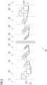
- Figure 3 depicts an example representation of an image-to-image machine learned network 100 trained to identify pathological changes, e.g., by outputting an image filter IF or by providing coordinates of pathological relevant changes.
- Image filter IF may be configured to suppress artefacts in the deformation field DF and/or enhancing pathological changes (e.g., if multiplied with the reference image data RI or follow-up image data FI).
- the network's 100 output is indicative of pathologically relevant changes between the reference image data RI and follow-up image data FI against anatomical deformations and artefacts comprised in the co-aligned image date CAI.
- the machine-learned network 100 takes as input the co-aligned image data CAI and is thereby provided with the image registration results (optionally including any model fitting results) alongside with the underlying (visual) image information in the form of reference image data RI and/or follow-up image data FI.
- the arrangement of the machine-learned network 100 is a neural network for deep learning. Other network arrangements may be used, such as a support vector machine. Deep architectures include convolutional neural networks (CNN) or deep belief nets (DBN).
- the arrangement of the machine learned network 100 is a fully convolutional network (FCN). Alternative network arrangements may be used, for example, a 3D Very Deep Convolutional Networks (3D-VGGNet).
- a VGGNet stacks many layer blocks containing narrow convolutional layers followed by max pooling layers.
- the machine-learned network 100 is defined in the form of a plurality of sequential layers 101-107.
- the term sequential is used to indicate the general flow of output feature values from one layer to input to a next layer. The information from the next layer is fed to a next layer, and so on until the final output layer.
- Layers 101-107 may only feed forward or may be bidirectional, including some feedback to a previous layer.
- the layers 101-107 may be weighted.
- each layer 101-107 generally comprises a number of nodes that are also weighted.
- each node can be seen as executing a mathematical operation mapping one or more input values to an output value.
- the nodes of each layer may connect with all or only a sub-set of nodes of a previous and/or subsequent layer. Two nodes are "connected” if their inputs and/or outputs are connected. Further, skip connections may be used, so that layers may also output to other layers than the sequentially next layer.
- layer 101 is the input layer.
- Input values for the nodes of layer 101 are image element values, preferably voxel values, and the deformation fields DF of the co-aligned image data CAI.
- Layer 107 is the output layer. Output values of the nodes of output layer 107 may be image element values of the image filter FI. As an alternative, output layer 107 may indicate pathological changes by outputting corresponding coordinates and values for the associated amount of change. In between input 101 and output layer 107 there is a number of hidden layers 102-106.
- Various layers may be used, such as convolutional 102, pooling 103 (e.g., max-pooling or average-pooling), up-sampling 105, deconvolutional 106, fully connected 104, or other types of layers.
- Convolutional layers convolve the input and pass its result to the next layer by moving an image filter kernel over the input.
- Pooling layers 103 reduce the dimensions of the data by combining the outputs of node clusters at one layer into a single node in the next layer, thereby streamlining the underlying computation.
- Up-sampling 105 and deconvolution layers 106 reverse the actions of convolution 102 and pooling layer 103 in terms of the abstraction level to reconstruct the output image (i.e., the image filter IF).
- a fully connected layer 104 connects every node in one layer to every node in another layer, so that essentially every feature gets a "vote".
- the machine-learned network 100 of this embodiment learns by adapting weights or weighting parameters of individual layers and nodes based on training data. Rather than pre-programming potential artefacts or pathological changes and trying to identify these in the co-aligned image data CAI, the machine learned network architecture is defined to learn these patterns at different levels of abstraction based on input data.
- the learning may be conceived as learning lower-level features (i.e., features at a more abstract or compressed level) of the pathological changes and/or deformation artefacts which are common and from which pathological changes and/or deformation artefacts may be reconstructed.
- this process is cascaded since in each layer learns features for reconstructing the features of the previous layer are learned, providing more abstraction (c.f., layers 102-104).
- layers 102-104 layers 102-104.
- subsequent units have more abstraction.
- Each node of a layer may be considered representing a feature.
- Different layers are provided for learning different features.
- one feature may be a line directly found in the co-aligned image data CAI.
- the next layer may combine lines, so that one of the new features is a corner or intersection.
- the next layer may combine features (e.g., the corner and length of lines) from a previous layer so that the next layer provides a shape indication.
- the level of abstraction reverses (c.f. layers 105-106). Each layer then reduces the level of abstraction or compression.
- the machine learned network 100 may preferably be trained using a method according to supervised learning. Well established is the backpropagation method, which may be applied for embodiments of the present invention.
- the machine learned network 100 is applied to training input values to produce corresponding output values the target values of which are known.
- the difference between produced and target output values e.g., in the form of the mean squared error (MSE) of the difference between produced and target values
- MSE mean squared error
- the goal of the training is to find a (local) minimum of the loss function by iteratively adjusting the weights of the machine learned network 100 so that the machine learned network 100 is finally enabled to generate acceptable results across a (sufficiently) large cohort of training data.
- This optimization problem can be carried out using stochastic gradient descent or other approaches known in the art.
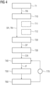
- Figure 4 depicts an inventive method for training a machine learned network 100 to recognize pathological changes if provided with (a) deformation field(s) DF between reference image data RI and follow-up image data FI, the deformation fields being generated by one or more image registrations and (b) the image data from reference image data RI and/or follow-up image data FI.
- the method comprises several steps. The order of the steps does not necessarily correspond to the numbering of the steps but may also vary between different embodiments of the present invention. Optional steps are shown with dashed frames in Figure 4 .
- a first step T1 is directed to provide a plurality of training reference image data sets TRI.
- the training reference image data sets TRI are preferably of the same type as the image data to be processed by the deployed and readily trained machine learned model. Accordingly, the training reference image data sets TRI each likewise show a body part of a patient comprising a plurality of anatomic structures and organs and have been acquired using one of the abovementioned medical imaging modalities.
- a subsequent step T10 is directed to generate a plurality of simulated follow up image data sets SFI by deforming each training reference image data set TRI using one or more biomechanical models of soft tissue deformation (subsequently also called “motion models").
- the models can be of the same kind as described before in connection with step M20. Alternatively, specifically adapted models might be used.
- the motion models may be applied in an "organ specific" fashion so that every organ and/or anatomy comprised in the training reference image data is deformed by applying a designated motion model.
- the step of deforming T10 might be preceded by a step of recognizing anatomic structures in the training reference image data.
- artefacts relate to non-physiological (non-anatomic) deformations which arise from image processing.
- pathological changes may be simulated as well (c.f., optional sub-step T12), e.g., by applying a designated modelling module to the training reference image data TRI.
- any metadata associated to the simulated pathological changes may be simulated as well, such as type, volume, cross-section, circumference, diameter, state of the contour, degree of calcification or fat deposition, degree of solidity, and so forth.
- subsequent step T20 one or more deformation fields DF are respectively calculated between each pair of training reference image data TRI and simulated follow-up image data SFI as described before in connection with step M20.
- a training co-aligned image data set is respectively generated from the pairs of training reference image data TRI and simulated follow-up image data SFI as described before in connection with step M30.
- the training co-aligned image data may be a deformed version of the training reference image data TRI.
- one training co-aligned image data is provided to the (not readily trained) machine learned model.
- the machine learned model will recognize any artefacts and/or pathological changes according to the learned task in step T40 as described in connection with step M40 above. In particular, this may involve generating an image filter IF for the underlying pair of training reference image data TRI and simulated follow-up image data SFI. If the pair contained artefacts in the deformation field DF, the corresponding image filter IF is supposed to filter these out. Further, the image filter IF may be supposed to enhance pathological changes if any.
- the performance of the machine learned model (i.e., the quality of the image filter) is evaluated in subsequent step T50.
- One way of implementing this would be comparing corresponding change visualization data CVI voxel-by-voxel (pixel-by-pixel). As explained above in connection with step M50, this involves subtracting the deformed training reference image data TRI from the simulated follow-up image data SFI and multiplying the result with the image filter IF. As the result should only contain (optionally highlighted) pathological changes (if any), it can be compared to a representation of the simulated pathological changes (in a desirable highlighting) in an otherwise empty image data set of the format of the training reference image data TRI.
- this comparative data will be empty altogether - as should be the change visualization data CVI.
- Another way of implementing the comparison would be comparing the image filters generated by the machine learned network 100 to corresponding image filters respectively computed from the knowledge about the simulated pathological changes.
- the comparison is used as a loss function to adjust weights of the machine learned network 100 (step T60).
- step T70 the steps of identifying pathological changes by the machine learned network 100 (step T40) and comparing the result to the known output (step T50) are repeated with paired sets of training reference image data TRI and simulated follow-up image data SFI until the machine learned network 100 is able to generate results that are acceptable (i.e., until a local minimum of the loss function is reached). Once all pairs have been used, pairs are randomly shuffled for the next pass.
- the training based on simulated follow-up image data SFI is preferably complemented by training based on "real" pairs of follow up image data in which the physiological changes have been appropriately annotated and highlighted by an expert.
Landscapes
- Engineering & Computer Science (AREA)
- Theoretical Computer Science (AREA)
- Physics & Mathematics (AREA)
- Health & Medical Sciences (AREA)
- General Health & Medical Sciences (AREA)
- General Physics & Mathematics (AREA)
- Biomedical Technology (AREA)
- Medical Informatics (AREA)
- Data Mining & Analysis (AREA)
- Computational Linguistics (AREA)
- Life Sciences & Earth Sciences (AREA)
- Molecular Biology (AREA)
- Computing Systems (AREA)
- General Engineering & Computer Science (AREA)
- Biophysics (AREA)
- Mathematical Physics (AREA)
- Software Systems (AREA)
- Artificial Intelligence (AREA)
- Evolutionary Computation (AREA)
- Radiology & Medical Imaging (AREA)
- Nuclear Medicine, Radiotherapy & Molecular Imaging (AREA)
- Computer Vision & Pattern Recognition (AREA)
- Public Health (AREA)
- Quality & Reliability (AREA)
- Epidemiology (AREA)
- Primary Health Care (AREA)
- Pathology (AREA)
- Databases & Information Systems (AREA)
- Image Analysis (AREA)
- Apparatus For Radiation Diagnosis (AREA)
- Image Processing (AREA)
Priority Applications (1)
| Application Number | Priority Date | Filing Date | Title |
|---|---|---|---|
| EP25175886.8A EP4579591A3 (de) | 2019-11-29 | 2019-11-29 | Verfahren und system zur identifizierung pathologischer veränderungen in medizinischen nachfolgebildern |
Applications Claiming Priority (2)
| Application Number | Priority Date | Filing Date | Title |
|---|---|---|---|
| EP19212525.0A EP3828818B1 (de) | 2019-11-29 | 2019-11-29 | Verfahren und system zur identifizierung von pathologischen veränderungen in medizinischen nachuntersuchungsbildern |
| EP25175886.8A EP4579591A3 (de) | 2019-11-29 | 2019-11-29 | Verfahren und system zur identifizierung pathologischer veränderungen in medizinischen nachfolgebildern |
Related Parent Applications (2)
| Application Number | Title | Priority Date | Filing Date |
|---|---|---|---|
| EP19212525.0A Division-Into EP3828818B1 (de) | 2019-11-29 | 2019-11-29 | Verfahren und system zur identifizierung von pathologischen veränderungen in medizinischen nachuntersuchungsbildern |
| EP19212525.0A Division EP3828818B1 (de) | 2019-11-29 | 2019-11-29 | Verfahren und system zur identifizierung von pathologischen veränderungen in medizinischen nachuntersuchungsbildern |
Publications (2)
| Publication Number | Publication Date |
|---|---|
| EP4579591A2 true EP4579591A2 (de) | 2025-07-02 |
| EP4579591A3 EP4579591A3 (de) | 2025-10-22 |
Family
ID=68732920
Family Applications (2)
| Application Number | Title | Priority Date | Filing Date |
|---|---|---|---|
| EP19212525.0A Active EP3828818B1 (de) | 2019-11-29 | 2019-11-29 | Verfahren und system zur identifizierung von pathologischen veränderungen in medizinischen nachuntersuchungsbildern |
| EP25175886.8A Pending EP4579591A3 (de) | 2019-11-29 | 2019-11-29 | Verfahren und system zur identifizierung pathologischer veränderungen in medizinischen nachfolgebildern |
Family Applications Before (1)
| Application Number | Title | Priority Date | Filing Date |
|---|---|---|---|
| EP19212525.0A Active EP3828818B1 (de) | 2019-11-29 | 2019-11-29 | Verfahren und system zur identifizierung von pathologischen veränderungen in medizinischen nachuntersuchungsbildern |
Country Status (3)
| Country | Link |
|---|---|
| US (1) | US12008759B2 (de) |
| EP (2) | EP3828818B1 (de) |
| CN (1) | CN112885453B (de) |
Families Citing this family (21)
| Publication number | Priority date | Publication date | Assignee | Title |
|---|---|---|---|---|
| US10783634B2 (en) * | 2017-11-22 | 2020-09-22 | General Electric Company | Systems and methods to deliver point of care alerts for radiological findings |
| US11893482B2 (en) * | 2019-11-14 | 2024-02-06 | Microsoft Technology Licensing, Llc | Image restoration for through-display imaging |
| KR102387928B1 (ko) * | 2020-07-06 | 2022-04-19 | 메디컬아이피 주식회사 | 의료영상을 기초로 인체 조직을 분석하는 방법 및 그 장치 |
| US20220068467A1 (en) * | 2020-08-31 | 2022-03-03 | International Business Machines Corporation | Simulated follow-up imaging |
| CN113538533B (zh) * | 2021-06-22 | 2023-04-18 | 南方医科大学 | 一种脊柱配准方法、装置、设备及计算机存储介质 |
| US12062153B2 (en) * | 2021-07-07 | 2024-08-13 | Canon Medical Systems Corporation | Apparatus, method, and non-transitory computer-readable storage medium for improving image quality of a medical image volume |
| TWI778759B (zh) * | 2021-08-23 | 2022-09-21 | 佛教慈濟醫療財團法人 | 醫療影像處理方法和設備、及其電腦儲存介質和電腦程式產品 |
| CN113989338B (zh) * | 2021-09-06 | 2024-11-08 | 北京东软医疗设备有限公司 | 图像配准方法及装置、存储介质及计算机设备 |
| CN114359356B (zh) * | 2021-12-28 | 2024-11-26 | 上海联影智能医疗科技有限公司 | 图像配准模型的训练方法、图像配准方法、设备及介质 |
| CN114359360B (zh) * | 2022-03-17 | 2022-06-10 | 成都信息工程大学 | 一种基于对抗的双向一致性约束医学图像配准算法 |
| EP4505407A4 (de) | 2022-04-22 | 2025-08-13 | Veytel Inc | Verfahren zur registrierung von zwei oder mehr patientenbildern zur zeitlichen änderungsbeurteilung |
| EP4270309A1 (de) * | 2022-04-25 | 2023-11-01 | Koninklijke Philips N.V. | Bildverarbeitungsvorrichtung und -verfahren |
| WO2024100240A1 (en) | 2022-11-10 | 2024-05-16 | Universiteit Antwerpen | Longitudinal magnetic resonance imaging method |
| CN115714025B (zh) * | 2022-11-29 | 2025-10-03 | 汤臣倍健股份有限公司 | 一种健康问答模型的训练、健康问答方法及相关装置 |
| EP4379672A1 (de) | 2022-11-29 | 2024-06-05 | Siemens Healthineers AG | Verfahren und systeme zur klassifizierung eines datensatzes medizinischer bilder |
| US20240282431A1 (en) * | 2023-02-17 | 2024-08-22 | GE Precision Healthcare LLC | System and method for automated longitudinal review |
| US20240420319A1 (en) * | 2023-06-15 | 2024-12-19 | Taipei Medical University | Devices and methods for detecting pulmonary function based on low-dose ct images |
| CN116894817B (zh) * | 2023-07-12 | 2025-09-02 | 上海交通大学 | 一种基于两阶段多任务学习的肿瘤进展评估方法 |
| EP4495939A1 (de) * | 2023-07-20 | 2025-01-22 | Siemens Healthineers AG | Verfahren und systeme zur bereitstellung eines medizinischen videoberichts |
| CN119048886B (zh) * | 2024-11-04 | 2025-01-28 | 中国空气动力研究与发展中心低速空气动力研究所 | 一种旋翼dic变形测量标识点识别方法及介质 |
| CN120107264A (zh) * | 2025-05-08 | 2025-06-06 | 深圳市朗帅科技有限公司 | 一种功率器件缺陷检测方法及系统 |
Citations (2)
| Publication number | Priority date | Publication date | Assignee | Title |
|---|---|---|---|---|
| US20110081066A1 (en) | 2009-10-07 | 2011-04-07 | Marie-Pierre Jolly | System and method for cardiac segmentation in mr-cine data using inverse consistent non-rigid registration |
| US20120235679A1 (en) | 2011-03-17 | 2012-09-20 | Siemens Corporation | Motion compensated magnetic resonance reconstruction in real-time imaging |
Family Cites Families (7)
| Publication number | Priority date | Publication date | Assignee | Title |
|---|---|---|---|---|
| US7653263B2 (en) * | 2005-06-30 | 2010-01-26 | General Electric Company | Method and system for volumetric comparative image analysis and diagnosis |
| US11576645B2 (en) * | 2015-03-02 | 2023-02-14 | Shanghai United Imaging Healthcare Co., Ltd. | Systems and methods for scanning a patient in an imaging system |
| US9767380B2 (en) * | 2015-04-13 | 2017-09-19 | Varian Medical Systems International Ag. | Image comparison tool tolerant to deformable image matching |
| US10842379B2 (en) | 2016-01-29 | 2020-11-24 | Siemens Healthcare Gmbh | Multi-modality image fusion for 3D printing of organ morphology and physiology |
| PL3554631T3 (pl) | 2016-12-13 | 2022-09-12 | Novocure Gmbh | Leczenie pacjentów polami ttfields ze zoptymalizowanymi pozycjami elektrod z wykorzystaniem odkształcalnych matryc |
| CN109003267B (zh) | 2017-08-09 | 2021-07-30 | 深圳科亚医疗科技有限公司 | 从3d图像自动检测目标对象的计算机实现方法和系统 |
| JP7229881B2 (ja) * | 2018-08-14 | 2023-02-28 | キヤノン株式会社 | 医用画像処理装置、学習済モデル、医用画像処理方法及びプログラム |
-
2019
- 2019-11-29 EP EP19212525.0A patent/EP3828818B1/de active Active
- 2019-11-29 EP EP25175886.8A patent/EP4579591A3/de active Pending
-
2020
- 2020-11-23 US US17/101,069 patent/US12008759B2/en active Active
- 2020-11-26 CN CN202011346976.6A patent/CN112885453B/zh active Active
Patent Citations (2)
| Publication number | Priority date | Publication date | Assignee | Title |
|---|---|---|---|---|
| US20110081066A1 (en) | 2009-10-07 | 2011-04-07 | Marie-Pierre Jolly | System and method for cardiac segmentation in mr-cine data using inverse consistent non-rigid registration |
| US20120235679A1 (en) | 2011-03-17 | 2012-09-20 | Siemens Corporation | Motion compensated magnetic resonance reconstruction in real-time imaging |
Also Published As
| Publication number | Publication date |
|---|---|
| EP3828818B1 (de) | 2025-06-18 |
| US20210166391A1 (en) | 2021-06-03 |
| CN112885453B (zh) | 2024-09-20 |
| EP4579591A3 (de) | 2025-10-22 |
| EP3828818A1 (de) | 2021-06-02 |
| CN112885453A (zh) | 2021-06-01 |
| EP3828818C0 (de) | 2025-06-18 |
| US12008759B2 (en) | 2024-06-11 |
Similar Documents
| Publication | Publication Date | Title |
|---|---|---|
| EP3828818B1 (de) | Verfahren und system zur identifizierung von pathologischen veränderungen in medizinischen nachuntersuchungsbildern | |
| US10699410B2 (en) | Automatic change detection in medical images | |
| US11430119B2 (en) | Spatial distribution of pathological image patterns in 3D image data | |
| US10304198B2 (en) | Automatic medical image retrieval | |
| US11423554B2 (en) | Registering a two-dimensional image with a three-dimensional image | |
| US12205706B2 (en) | Method and system for computer aided detection of abnormalities in image data | |
| JP5520543B2 (ja) | 階層化メッシュに基づくデータの半自動整合 | |
| US11229377B2 (en) | System and method for next-generation MRI spine evaluation | |
| JP7457011B2 (ja) | 異常検出方法、異常検出プログラム、異常検出装置、サーバ装置及び情報処理方法 | |
| US20170221204A1 (en) | Overlay Of Findings On Image Data | |
| US12190522B2 (en) | Constrained object correction for a segmented image | |
| WO2016063235A2 (en) | Visualization of imaging uncertainty | |
| EP3989172A1 (de) | Verfahren zur erzeugung einer computerbasierten visualisierung von medizinischen 3d-bilddaten | |
| CN116664476A (zh) | 确定医学图像数据中描绘的解剖异常的变化的方法和系统 | |
| Balashova et al. | 3D organ shape reconstruction from Topogram images | |
| Lee et al. | Automatic left and right lung separation using free-formed surface fitting on volumetric CT | |
| EP4339961A1 (de) | Verfahren und systeme zur bereitstellung einer vorlagendatenstruktur für einen medizinischen bericht | |
| US11645767B2 (en) | Capturing a misalignment | |
| US12482123B2 (en) | Making measurements in images | |
| Sarkar | Deep Learning in Medical Imaging | |
| Javale et al. | Reconstruction of Greyscale X-Ray for Boundary Analysis of Anatomical Structure | |
| Medina et al. | Accuracy of connected confidence left ventricle segmentation in 3-D multi-slice computerized tomography images | |
| CN117252940A (zh) | 重建医学影像的方法、装置及电子设备 | |
| La Cruz | 3D modelling and reconstruction of peripheral arteries | |
| Şener | Automatic bayesian segmentation of human facial tissue using 3D MR-CT fusion by incorporating models of measurement blurring, noise and partial volume |
Legal Events
| Date | Code | Title | Description |
|---|---|---|---|
| PUAI | Public reference made under article 153(3) epc to a published international application that has entered the european phase |
Free format text: ORIGINAL CODE: 0009012 |
|
| STAA | Information on the status of an ep patent application or granted ep patent |
Free format text: STATUS: THE APPLICATION HAS BEEN PUBLISHED |
|
| AC | Divisional application: reference to earlier application |
Ref document number: 3828818 Country of ref document: EP Kind code of ref document: P |
|
| AK | Designated contracting states |
Kind code of ref document: A2 Designated state(s): AL AT BE BG CH CY CZ DE DK EE ES FI FR GB GR HR HU IE IS IT LI LT LU LV MC MK MT NL NO PL PT RO RS SE SI SK SM TR |
|
| PUAL | Search report despatched |
Free format text: ORIGINAL CODE: 0009013 |
|
| AK | Designated contracting states |
Kind code of ref document: A3 Designated state(s): AL AT BE BG CH CY CZ DE DK EE ES FI FR GB GR HR HU IE IS IT LI LT LU LV MC MK MT NL NO PL PT RO RS SE SI SK SM TR |
|
| RIC1 | Information provided on ipc code assigned before grant |
Ipc: G06T 7/00 20170101AFI20250917BHEP |