EP4579462A2 - Improved architectures for storing and retrieving system data in a non-volatile memory system - Google Patents
Improved architectures for storing and retrieving system data in a non-volatile memory system Download PDFInfo
- Publication number
- EP4579462A2 EP4579462A2 EP25176395.9A EP25176395A EP4579462A2 EP 4579462 A2 EP4579462 A2 EP 4579462A2 EP 25176395 A EP25176395 A EP 25176395A EP 4579462 A2 EP4579462 A2 EP 4579462A2
- Authority
- EP
- European Patent Office
- Prior art keywords
- volatile memory
- word
- data
- cells
- nvm
- Prior art date
- Legal status (The legal status is an assumption and is not a legal conclusion. Google has not performed a legal analysis and makes no representation as to the accuracy of the status listed.)
- Pending
Links
Images





Classifications
-
- G—PHYSICS
- G06—COMPUTING OR CALCULATING; COUNTING
- G06F—ELECTRIC DIGITAL DATA PROCESSING
- G06F11/00—Error detection; Error correction; Monitoring
- G06F11/07—Responding to the occurrence of a fault, e.g. fault tolerance
- G06F11/08—Error detection or correction by redundancy in data representation, e.g. by using checking codes
- G06F11/10—Adding special bits or symbols to the coded information, e.g. parity check, casting out 9's or 11's
- G06F11/1008—Adding special bits or symbols to the coded information, e.g. parity check, casting out 9's or 11's in individual solid state devices
- G06F11/1048—Adding special bits or symbols to the coded information, e.g. parity check, casting out 9's or 11's in individual solid state devices using arrangements adapted for a specific error detection or correction feature
-
- G—PHYSICS
- G06—COMPUTING OR CALCULATING; COUNTING
- G06F—ELECTRIC DIGITAL DATA PROCESSING
- G06F11/00—Error detection; Error correction; Monitoring
- G06F11/07—Responding to the occurrence of a fault, e.g. fault tolerance
- G06F11/08—Error detection or correction by redundancy in data representation, e.g. by using checking codes
- G06F11/10—Adding special bits or symbols to the coded information, e.g. parity check, casting out 9's or 11's
- G06F11/1008—Adding special bits or symbols to the coded information, e.g. parity check, casting out 9's or 11's in individual solid state devices
- G06F11/1068—Adding special bits or symbols to the coded information, e.g. parity check, casting out 9's or 11's in individual solid state devices in sector programmable memories, e.g. flash disk
-
- G—PHYSICS
- G11—INFORMATION STORAGE
- G11C—STATIC STORES
- G11C11/00—Digital stores characterised by the use of particular electric or magnetic storage elements; Storage elements therefor
- G11C11/56—Digital stores characterised by the use of particular electric or magnetic storage elements; Storage elements therefor using storage elements with more than two stable states represented by steps, e.g. of voltage, current, phase, frequency
- G11C11/5621—Digital stores characterised by the use of particular electric or magnetic storage elements; Storage elements therefor using storage elements with more than two stable states represented by steps, e.g. of voltage, current, phase, frequency using charge storage in a floating gate
- G11C11/5642—Sensing or reading circuits; Data output circuits
-
- G—PHYSICS
- G11—INFORMATION STORAGE
- G11C—STATIC STORES
- G11C16/00—Erasable programmable read-only memories
- G11C16/02—Erasable programmable read-only memories electrically programmable
- G11C16/06—Auxiliary circuits, e.g. for writing into memory
- G11C16/26—Sensing or reading circuits; Data output circuits
-
- G—PHYSICS
- G11—INFORMATION STORAGE
- G11C—STATIC STORES
- G11C16/00—Erasable programmable read-only memories
- G11C16/02—Erasable programmable read-only memories electrically programmable
- G11C16/06—Auxiliary circuits, e.g. for writing into memory
- G11C16/34—Determination of programming status, e.g. threshold voltage, overprogramming or underprogramming, retention
- G11C16/3418—Disturbance prevention or evaluation; Refreshing of disturbed memory data
- G11C16/3427—Circuits or methods to prevent or reduce disturbance of the state of a memory cell when neighbouring cells are read or written
-
- G—PHYSICS
- G11—INFORMATION STORAGE
- G11C—STATIC STORES
- G11C29/00—Checking stores for correct operation ; Subsequent repair; Testing stores during standby or offline operation
- G11C29/52—Protection of memory contents; Detection of errors in memory contents
-
- G—PHYSICS
- G11—INFORMATION STORAGE
- G11C—STATIC STORES
- G11C29/00—Checking stores for correct operation ; Subsequent repair; Testing stores during standby or offline operation
- G11C29/70—Masking faults in memories by using spares or by reconfiguring
- G11C29/74—Masking faults in memories by using spares or by reconfiguring using duplex memories, i.e. using dual copies
-
- G—PHYSICS
- G11—INFORMATION STORAGE
- G11C—STATIC STORES
- G11C5/00—Details of stores covered by group G11C11/00
- G11C5/005—Circuit means for protection against loss of information of semiconductor storage devices
-
- G—PHYSICS
- G11—INFORMATION STORAGE
- G11C—STATIC STORES
- G11C7/00—Arrangements for writing information into, or reading information out from, a digital store
- G11C7/06—Sense amplifiers; Associated circuits, e.g. timing or triggering circuits
- G11C7/08—Control thereof
-
- G—PHYSICS
- G11—INFORMATION STORAGE
- G11C—STATIC STORES
- G11C7/00—Arrangements for writing information into, or reading information out from, a digital store
- G11C7/10—Input/output [I/O] data interface arrangements, e.g. I/O data control circuits, I/O data buffers
- G11C7/1006—Data managing, e.g. manipulating data before writing or reading out, data bus switches or control circuits therefor
- G11C7/1012—Data reordering during input/output, e.g. crossbars, layers of multiplexers, shifting or rotating
-
- H—ELECTRICITY
- H03—ELECTRONIC CIRCUITRY
- H03K—PULSE TECHNIQUE
- H03K19/00—Logic circuits, i.e. having at least two inputs acting on one output; Inverting circuits
- H03K19/20—Logic circuits, i.e. having at least two inputs acting on one output; Inverting circuits characterised by logic function, e.g. AND, OR, NOR, NOT circuits
-
- G—PHYSICS
- G11—INFORMATION STORAGE
- G11C—STATIC STORES
- G11C29/00—Checking stores for correct operation ; Subsequent repair; Testing stores during standby or offline operation
- G11C29/04—Detection or location of defective memory elements, e.g. cell constructio details, timing of test signals
- G11C2029/0409—Online test
-
- G—PHYSICS
- G11—INFORMATION STORAGE
- G11C—STATIC STORES
- G11C29/00—Checking stores for correct operation ; Subsequent repair; Testing stores during standby or offline operation
- G11C29/04—Detection or location of defective memory elements, e.g. cell constructio details, timing of test signals
- G11C2029/0411—Online error correction
-
- G—PHYSICS
- G11—INFORMATION STORAGE
- G11C—STATIC STORES
- G11C29/00—Checking stores for correct operation ; Subsequent repair; Testing stores during standby or offline operation
- G11C29/04—Detection or location of defective memory elements, e.g. cell constructio details, timing of test signals
- G11C29/08—Functional testing, e.g. testing during refresh, power-on self testing [POST] or distributed testing
- G11C29/12—Built-in arrangements for testing, e.g. built-in self testing [BIST] or interconnection details
- G11C2029/4402—Internal storage of test result, quality data, chip identification, repair information
-
- G—PHYSICS
- G11—INFORMATION STORAGE
- G11C—STATIC STORES
- G11C29/00—Checking stores for correct operation ; Subsequent repair; Testing stores during standby or offline operation
- G11C29/04—Detection or location of defective memory elements, e.g. cell constructio details, timing of test signals
- G11C29/50—Marginal testing, e.g. race, voltage or current testing
- G11C2029/5006—Current
-
- G—PHYSICS
- G11—INFORMATION STORAGE
- G11C—STATIC STORES
- G11C29/00—Checking stores for correct operation ; Subsequent repair; Testing stores during standby or offline operation
- G11C29/04—Detection or location of defective memory elements, e.g. cell constructio details, timing of test signals
- G11C29/50—Marginal testing, e.g. race, voltage or current testing
-
- G—PHYSICS
- G11—INFORMATION STORAGE
- G11C—STATIC STORES
- G11C7/00—Arrangements for writing information into, or reading information out from, a digital store
- G11C7/02—Arrangements for writing information into, or reading information out from, a digital store with means for avoiding parasitic signals
Definitions
- Numerous embodiments are disclosed of improved architectures for storing and retrieving system data in a non-volatile memory system.
- Non-volatile memory systems are well-known in the prior art.
- Figure 1 depicts prior art non-volatile memory system 100.
- Non-volatile memory system 100 comprises array 101, row decoder 102, column decoder 103, and sense amplifier 104.
- Array 101 comprises an array of non-volatile memory cells arranged in rows and columns.
- Row decoder 102 is coupled to each row of non-volatile memory cells in array 101 and enables one or more rows for read, erase, or program operations, typically in response to a received row address.
- Column decoder 103 is coupled to each column of non-volatile memory cells in array 101 and enables one or more columns for read, erase, or program operations, typically in response to a received column address.
- row decoder 102 typically is coupled to a word line of each row of cells
- column decoder 103 typically is coupled to a bit line of each column of cells.
- Sense amplifier 104 is used during a read operation to sense the value stored in the selected cell or cells.
- each memory cell 210 includes source region 14 and drain region 16 formed in semiconductor substrate 12, with channel region 18 there between.
- Floating gate 20 is formed over and insulated from (and controls the conductivity of) a first portion of the channel region 18, and over a portion of the source region 14.
- Word line terminal 22 (which is typically coupled to a word line) has a first portion that is disposed over and insulated from (and controls the conductivity of) a second portion of the channel region 18, and a second portion that extends up and over the floating gate 20.
- the floating gate 20 and word line terminal 22 are insulated from the substrate 12 by a gate oxide.
- Bitline 24 is coupled to drain region 16.
- Memory cell 210 is erased (where electrons are removed from the floating gate) by placing a high positive voltage on the word line terminal 22 in relation to the substrate region 12 which causes electrons on the floating gate 20 to tunnel through the intermediate insulation from the floating gate 20 to the word line terminal 22 via Fowler-Nordheim tunneling.
- Memory cell 210 is programmed (where electrons are placed on the floating gate) by placing a positive voltage on the word line terminal 22, and a positive voltage on the source region 14. Electrons will flow from the drain region 16 toward the source region 14. The electrons will accelerate and become heated when they move through the channel region 18 under the gap between the word line terminal 22 and the floating gate 20, and the channel region 18 under the floating gate 20. Some of the heated electrons will be injected through the gate oxide onto the floating gate 20 due to the attractive electrostatic force from the floating gate 20 and the reduction in oxide energy barrier caused by said force.
- Memory cell 210 is read by placing positive read voltages on the drain region 16 and word line terminal 22 (which turns on the portion of the channel region 18 under the word line terminal) in relation to the source region 14. If the floating gate 20 is positively charged (i.e. erased of electrons), then the portion of the channel region 18 under the floating gate 20 is turned on as well, and current will flow across the channel region 18 to the source region 14, which is sensed as the erased or "1" state. If the floating gate 20 is negatively charged (i.e. programmed with electrons), then the portion of the channel region under the floating gate 20 is mostly or entirely turned off, and current will not flow (or there will be little flow) across the channel region 18 to the source region 14, which is sensed as the programmed or "0" state.
- the floating gate 20 is positively charged (i.e. erased of electrons)
- the portion of the channel region 18 under the floating gate 20 is turned on as well, and current will flow across the channel region 18 to the source region 14, which is sensed as the erased or "1" state
- Table No. 1 depicts typical voltage/current ranges that can be applied to the terminals of memory cell 210 for performing read, erase, and program operations: Table No. 1: Operation of Flash Memory Cell 210 of Figure 3 WL BL SL Read 2-3V 0.6-2V 0V Erase ⁇ 11-13V 0V 0V Program 1-2V 0.1-3 ⁇ A 9-10V
- Figure 3 depicts a four-gate memory cell 310 comprising source region 14, drain region 16, floating gate 20 over a first portion of channel region 18, a select gate 22 (typically coupled to a word line, WL) over a second portion of the channel region 18, a control gate 28 over the floating gate 20, and an erase gate 30 over the source region 14.
- WL word line
- FIG. 3 depicts a four-gate memory cell 310 comprising source region 14, drain region 16, floating gate 20 over a first portion of channel region 18, a select gate 22 (typically coupled to a word line, WL) over a second portion of the channel region 18, a control gate 28 over the floating gate 20, and an erase gate 30 over the source region 14.
- WL word line
- erase gate 30 over the source region 14.
- All gates are non-floating gates except floating gate 20, meaning that they are electrically connected or connectable to a voltage source. Programming is performed by heated electrons from the channel region 18 injecting themselves onto the floating gate 20. Erasing is performed by electrons tunneling from the floating gate
- Table No. 2 depicts typical voltage/current ranges that can be applied to the terminals of memory cell 310 for performing read, erase, and program operations: Table No. 2: Operation of Flash Memory Cell 310 of Figure 3 WL/SG BL CG EG SL Read 0.7-3.6V 0.4-2V 0-3.6V 0-3.6V 0V Erase 0V 0V 0V/-8V 8-12V 0V Program 0.5-2V 0.1-1 ⁇ A 8-11V 4-8V 4-5V
- Table No. 3 depicts typical voltage/current ranges that can be applied to the terminals of memory cell 410 for performing read, erase, and program operations: Table No. 3: Operation of Flash Memory Cell 410 of Figure 4 WL/SG BL EG SL Read 0.7-3.6V 0.4-2V 0-3.6V 0V Erase 0V 0V 10-12V 0V Program 0.5-2V 0.5-3 ⁇ A 4.5V 7-9V
- non-volatile memory technologies such as FINFET split gate flash or stack gate flash memory, NAND flash, SONOS (silicon-oxide-nitride-oxide-silicon, charge trap in nitride), MONOS (metal-oxide-nitride-oxide-silicon, metal charge trap in nitride), ReRAM (resistive ram), PCM (phase change memory), MRAM (magnetic ram), FeRAM (ferroelectric ram), CT (charge trap) memory, CN (carbon-nanotube) memory, OTP (bi-level or multi-level one time programmable), and CeRAM (correlated electron ram), without limitation.
- SONOS silicon-oxide-nitride-oxide-silicon, charge trap in nitride
- MONOS metal-oxide-nitride-oxide-silicon, metal charge trap in nitride
- ReRAM resistive ram
- PCM phase change memory
- MRAM magnetic ram
- the data stored in protected area 501 is critical to the accurate functioning of non-volatile memory system 100, the data stored in protected area 501 needs extra protection from low-probability data loss events such as charge loss, charge movement, read disturb, radiation-induced soft errors, and other mechanisms which cause changes in the read current/voltage of a small fraction of the cells.
- One prior art approach is to store each system bit in protected area 501 in two non-volatile memory cells in a redundant fashion.
- the read current from the two cells can be summed and compared against a reference value to determine the stored value.
- system data is much less likely to become corrupted due to charge loss, charge redistribution, disturb effects, and other phenomena that have caused data corruption in prior art non-volatile memory systems.
- a non-volatile memory system comprises an array of non-volatile memory cells arranged into rows and columns; a sense amplifier configured during a read operation to receive current from a first non-volatile memory cell in a first column of the array and to indicate a first value stored in the first non-volatile memory cell and to receive current from a second non-volatile memory cell in a second column of the array and to indicate a second value stored in the second non-volatile memory cell; and a logic circuit for receiving from the sense amplifier the first value and the second value and for generating a data bit output based on the first value and the second value.
- a non-volatile memory system comprises an array of non-volatile memory cells arranged into rows and columns; and a sense amplifier configured during a read operation to receive combined current from a first non-volatile memory cell and a second non-volatile memory cell in a selected column of the array and to generate a data bit output indicating a value based on the combined current.
- a non-volatile memory system comprises an array of non-volatile memory cells arranged into rows and columns, each row comprising a word of non-volatile memory cells and error correction code data calculated from the word; a sense amplifier configured during a read operation to receive current from the array and to output a word and error correction code data for the word; and an error correction code engine for correcting one or more errors in the word using the error correction code data for the word.
- FIGS. 6-8 depict embodiments that are particularly suitable for non-volatile memory (NVM) cell designs where a charge loss, charge redistribution, disturb, or other physical or electrical changes in the NVM cell will cause a cell to gravitate towards a "1" state, which might flip a stored "0" to a "1” but will not affect a stored "1".
- NVM non-volatile memory
- FIG 6 depicts system data architecture 600.
- Each bit of system data is written into two redundant NVM cells, such as cells 601 and 602, located in the same row accessible by the same word line, such as wordline 601, and in different columns accessible by different bit lines, such as bit lines 604 and 605.
- NVM cells 601 and 602 are simultaneously but independently sensed by sense amplifier 104 against a reference current to determine their respective logic states.
- Data read from the two cells as output by sense amplifier 104 (which indicates a first value stored one of the two NVM cells 601, 602 and a second value stored in the other of the two NVM cells 601, 602) are routed through AND device 603 (a logic device performing an AND function, which can be implemented using hardware logic or by firmware executed on a controller or processor) to generate the final system data (indicated by "Output").
- AND device 603 a logic device performing an AND function, which can be implemented using hardware logic or by firmware executed on a controller or processor
- NVM cells 601 and 602 originally stored a "0” and neither cell has flipped, then the output will be a "0". If NVM cells 601 and 602 originally stored a “0” and one of the two NVM cells 601, 602 has flipped from a "0" to a “1,” the output will still be a "0” because the output of AND device 603 will be “0". The probability of both NVM cells flipping from a "0" to a "1" is extremely low.
- NVM cells 601 and 602 originally stored a 1, then it is expected that both NVM cells 601 and 602 will still store a "1" because the underlying NVM cell architecture is assumed to be of the type where a leakage or disturb will cause a "0" to flip to a "1” but will not cause a "1” to flip to a "0".
- Bitline 606 and wordline 603 are shown for completeness.
- Figure 7 depicts system data architecture 700.
- Each bit of system data is written into two redundant NVM cells.
- the redundant NVM cells each can be located in any row and in any column. That is, there is no restriction on where the redundant NVM cells can be placed, and they need not be located in the same row or column or adjacent rows or columns.
- a pair of redundant bits are stored in NVM cell 701 accessible by wordline 601 and bit line 604 and in NVM cell 702 accessible by wordline 603 and bitline 606. Bitline 602 and wordline 605 are shown for completeness.
- NVM cells 701 and 702 are independently sensed by sense amplifier 104 against a reference current to determine their respective logic states.
- Read data from the two NVM cells output by sense amplifier 104 (which indicates a first value stored one of the two NVM cells 701, 702 and a second value stored in the other of the two NVM cells 701, 702) are processed with AND device 603 (a logic device performing an AND function, which can be implemented using hardware logic or by firmware executed on a controller or processor) to generate the final system data (indicated by "Output").
- AND device 603 a logic device performing an AND function, which can be implemented using hardware logic or by firmware executed on a controller or processor
- NVM cells 701 and 702 originally stored a "0" and neither cell has flipped, then the output will be a "0". If NVM cells 701 and 702 originally stored a “0” and one of the two NVM cells 701, 702 has flipped from a "0" to a "1,” the final data will still be a "0” because the output of the AND operation will be "0". The probability of both NVM cells 701 and 702 flipping from a "0" to a "1" is extremely low.
- NVM cells 701 and 702 originally stored a "1"
- NVM cell architecture is assumed to be of the type where a leakage, disturb, or other changes will cause a "0" to flip to a "1” but will not cause a "1” to flip to a "0".
- FIG 8 depicts system data architecture 800.
- Each bit of system data is written into two redundant NVM cells, such as NVM cells 801 and 802, located in the same column accessible by the same bit line, such as bitline 604, but located in different rows accessible by different wordlines, such as wordlines 601 and 603.
- Bitlines 605, 606 and wordline 602 are shown for completeness.
- both wordlines 601 and 603 are selected.
- Read current from NVM cells 801 and 802 are combined in the common bitline 604.
- the summed current is sensed by sense amplifier 104 against a reference current to determine its logic state.
- the reference current is set to a level within a range which is: higher than the sum of a typical 0-state read current for the NVM cells and the upper limit of a neutral floating gate (FG) read current (for NVM cells which use charge storage in a polysilicon FG, where the upper limit refers to the upper limit of the range of neutral FG read current for NVM cells in the array); or higher than the sum of typical 0-state read current plus the saturation point of 0-state read current movement (for NVM cells which use other storage mechanisms).
- the reference level is also lower than two times the lower limit of read current of 1-state cells which are read immediately after being set to 1-state.
- a read with the reference current within the above mentioned range is performed on the protected area 501, to guarantee that the two NVM cells 801 and 802 can be erased sufficiently to ensure the combined read current exceeds the reference level, under worst-case erase and read conditions, where the "worst case” is the weakest erase and read conditions across specified process/temperature/voltage ranges, which can vary from technology to technology. These conditions typically are captured during testing.
- NVM cells 801 and 802 originally stored a "1"
- NVM cells 801, 802 will still store a "1” because the underlying NVM cell architecture is assumed to be of the type where a leakage, disturb, or other changes will cause a "0" to flip to a "1” but will not cause a "1” to flip to a "0".
- Figures 9-10 depict embodiments that are particularly suitable for NVM cell designs where a charge loss, charge redistribution, or disturb will cause a cell to gravitate towards a "0" state, which might flip a stored "1" to a "0” but will not affect a stored "0".
- Figure 9 depicts system data architecture 900.
- Each bit of system data is written into two redundant NVM cells, such as cells 901 and 902, located in the same row accessible by the same wordline, such as wordline 601, but located in different columns accessible by different bitlines, such as bitlines 604 and 605.
- Bitline 606 and wordlines 602, 603 are shown for completeness.
- NVM cells 901 and 902 originally stored a "1" and neither cell has flipped, then the output will be a "1". If NVM cells 901 and 902 originally stored a “1” and one of the two NVM cells has flipped from a “1” to a "0,” the final data will still be a "1” because the output of OR device 903 will be "0". The probability of both NVM cells 901, 902 flipping from a "1" to a "0" is extremely low.
- NVM cells 901 and 902 originally stored a "0"
- NVM cells 901, 902 will still store a “0” because this scheme will only be used in NVM cell architecture where leakage, disturb, or other changes will cause a "1” to flip to a "0” but will not cause a "0” to flip.
- Figure 10 depicts system data architecture 1000. Each bit of system data is written into two redundant NVM cells.
- the redundant NVM cells each can be located in any row and column. That is, there is no restriction on where the NVM cells can be placed, and they need not be located in the same row or column or adjacent rows or columns.
- NVM cells 1001 and 1002 originally stored a "1" and neither NVM cell has flipped, then the output will be a "1". If NVM cells 1001 and 1002 originally stored a “1” and one of the two NVM cells has flipped from a "1" to a "0,” the final data will still be a "1” because the output of OR device 903 will be "0". The probability of both NVM cells 1001, 1002 flipping from a "1" to a "0" is extremely low.
- NVM cells 1001 and 1002 originally stored a "0"
- NVM cells 1001, 1002 will still store a “0” because this scheme will only be used in NVM cell architecture where leakage, disturb, or other changes will cause a "1” to flip to a "0” but will not cause a "0” to flip.
- Figure 11 depicts system data architecture 1100.
- each word of system data such as word 1101
- ECC error correction code
- Each system bit is stored in a word and is stored without redundancy. Multiple words may be stored in a row, each with there associated error correction code data, without exceeding the scope.
- ECC data 1102 is generated for word 1101 using an ECC, such as the Hamming code, or a code generated by the majority voter algorithm (where data is stored in N redundant physical cells and the value of the stored data is deemed to be the value indicated by a majority of the N cells), to perform error detection and error correction such as 2-bit error detection and 1-bit error correction scheme.
- ECC data 1102 a parity bit scheme may be utilized to indicate error detection without correction.
- sense amplifier 104 receives current from the array and outputs a word and error correction code data for the word to ECC engine 1103. If any single bit in word 1101 has flipped in either direction, the error will be detected and/or corrected successfully by ECC engine 1103. The probability of more than one bit flipping is extremely low.
- system data architecture 1100 is additionally implemented with redundancy such as using multiple cells for each system bit to further enhance the reliability such as for functional safety for automotive applications.
- each system bit can be stored in two cells in two rows or two columns, as described in previous embodiments.
- ECC engine 1103 is implemented using an external controller or firmware.
- the term “adjacent” includes “directly adjacent” (no intermediate materials, elements or space disposed therebetween) and “indirectly adjacent” (intermediate materials, elements or space disposed there between), “mounted to” includes “directly mounted to” (no intermediate materials, elements or space disposed there between) and “indirectly mounted to” (intermediate materials, elements or spaced disposed there between), and “electrically coupled” includes “directly electrically coupled to” (no intermediate materials or elements there between that electrically connect the elements together) and “indirectly electrically coupled to” (intermediate materials or elements there between that electrically connect the elements together).
- forming an element "over a substrate” can include forming the element directly on the substrate with no intermediate materials/elements therebetween, as well as forming the element indirectly on the substrate with one or more intermediate materials/elements there between.
Landscapes
- Engineering & Computer Science (AREA)
- Theoretical Computer Science (AREA)
- Physics & Mathematics (AREA)
- General Engineering & Computer Science (AREA)
- General Physics & Mathematics (AREA)
- Quality & Reliability (AREA)
- Computer Hardware Design (AREA)
- Computing Systems (AREA)
- Mathematical Physics (AREA)
- Read Only Memory (AREA)
- Techniques For Improving Reliability Of Storages (AREA)
- For Increasing The Reliability Of Semiconductor Memories (AREA)
- Information Retrieval, Db Structures And Fs Structures Therefor (AREA)
Abstract
Description
- This application claims priority to
U.S. Provisional Patent Application No. 63/131,624, filed on December 29, 2020 U.S. Patent Application No. 17/199,383, filed on March 11, 2021 - Numerous embodiments are disclosed of improved architectures for storing and retrieving system data in a non-volatile memory system.
- Non-volatile memory systems are well-known in the prior art.
Figure 1 depicts prior art non-volatilememory system 100.Non-volatile memory system 100 comprisesarray 101,row decoder 102,column decoder 103, andsense amplifier 104.Array 101 comprises an array of non-volatile memory cells arranged in rows and columns.Row decoder 102 is coupled to each row of non-volatile memory cells inarray 101 and enables one or more rows for read, erase, or program operations, typically in response to a received row address.Column decoder 103 is coupled to each column of non-volatile memory cells inarray 101 and enables one or more columns for read, erase, or program operations, typically in response to a received column address. When the non-volatile memory cells are flash memory cells,row decoder 102 typically is coupled to a word line of each row of cells, andcolumn decoder 103 typically is coupled to a bit line of each column of cells.Sense amplifier 104 is used during a read operation to sense the value stored in the selected cell or cells. - Various designs of non-volatile memory cells are known in the prior art. For example,
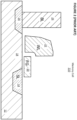
U.S. Patent 5,029,130 ("the '130 patent"), which is incorporated herein by reference, discloses an array of split gate non-volatile memory cells, which are a type of flash memory cells. Such amemory cell 210 is shown inFigure 2 . Eachmemory cell 210 includessource region 14 anddrain region 16 formed insemiconductor substrate 12, withchannel region 18 there between. Floatinggate 20 is formed over and insulated from (and controls the conductivity of) a first portion of thechannel region 18, and over a portion of thesource region 14. Word line terminal 22 (which is typically coupled to a word line) has a first portion that is disposed over and insulated from (and controls the conductivity of) a second portion of thechannel region 18, and a second portion that extends up and over thefloating gate 20. Thefloating gate 20 andword line terminal 22 are insulated from thesubstrate 12 by a gate oxide.Bitline 24 is coupled todrain region 16. -
Memory cell 210 is erased (where electrons are removed from the floating gate) by placing a high positive voltage on theword line terminal 22 in relation to thesubstrate region 12 which causes electrons on thefloating gate 20 to tunnel through the intermediate insulation from thefloating gate 20 to theword line terminal 22 via Fowler-Nordheim tunneling. -
Memory cell 210 is programmed (where electrons are placed on the floating gate) by placing a positive voltage on theword line terminal 22, and a positive voltage on thesource region 14. Electrons will flow from thedrain region 16 toward thesource region 14. The electrons will accelerate and become heated when they move through thechannel region 18 under the gap between theword line terminal 22 and thefloating gate 20, and thechannel region 18 under thefloating gate 20. Some of the heated electrons will be injected through the gate oxide onto thefloating gate 20 due to the attractive electrostatic force from thefloating gate 20 and the reduction in oxide energy barrier caused by said force. -
Memory cell 210 is read by placing positive read voltages on thedrain region 16 and word line terminal 22 (which turns on the portion of thechannel region 18 under the word line terminal) in relation to thesource region 14. If thefloating gate 20 is positively charged (i.e. erased of electrons), then the portion of thechannel region 18 under thefloating gate 20 is turned on as well, and current will flow across thechannel region 18 to thesource region 14, which is sensed as the erased or "1" state. If thefloating gate 20 is negatively charged (i.e. programmed with electrons), then the portion of the channel region under thefloating gate 20 is mostly or entirely turned off, and current will not flow (or there will be little flow) across thechannel region 18 to thesource region 14, which is sensed as the programmed or "0" state. - Table No. 1 depicts typical voltage/current ranges that can be applied to the terminals of
memory cell 210 for performing read, erase, and program operations:Table No. 1: Operation of Flash Memory Cell 210 of Figure 3WL BL SL Read 2-3V 0.6-2V 0V Erase ~11-13V 0V 0V Program 1-2V 0.1-3µA 9-10V - Other split gate memory cell configurations, which are other types of flash memory cells, are known. For example,
Figure 3 depicts a four-gatememory cell 310 comprisingsource region 14,drain region 16, floatinggate 20 over a first portion ofchannel region 18, a select gate 22 (typically coupled to a word line, WL) over a second portion of thechannel region 18, acontrol gate 28 over thefloating gate 20, and anerase gate 30 over thesource region 14. This configuration is described inU.S. Patent 7,868,375 , which is incorporated herein by reference for all purposes. Here, all gates are non-floating gates except floatinggate 20, meaning that they are electrically connected or connectable to a voltage source. Programming is performed by heated electrons from thechannel region 18 injecting themselves onto thefloating gate 20. Erasing is performed by electrons tunneling from thefloating gate 20 to theerase gate 30. - Table No. 2 depicts typical voltage/current ranges that can be applied to the terminals of
memory cell 310 for performing read, erase, and program operations:Table No. 2: Operation of Flash Memory Cell 310 of Figure 3WL/SG BL CG EG SL Read 0.7-3.6V 0.4-2V 0-3.6V 0-3.6V 0V Erase 0V 0V 0V/-8V 8-12V 0V Program 0.5-2V 0.1-1µA 8-11V 4-8V 4-5V -
Figure 4 depicts a three-gatememory cell 410, which is another type of flash memory cell.Memory cell 410 is identical to thememory cell 310 ofFigure 3 except thatmemory cell 410 does not have a separate control gate. The erase operation (whereby erasing occurs through use of the erase gate) and read operation are similar to that of theFigure 3 except there is no control gate bias applied. The programming operation also is done without the control gate bias, and as a result, a higher voltage must be applied on the source line during a program operation to compensate for a lack of control gate bias. - Table No. 3 depicts typical voltage/current ranges that can be applied to the terminals of
memory cell 410 for performing read, erase, and program operations:Table No. 3: Operation of Flash Memory Cell 410 of Figure 4WL/SG BL EG SL Read 0.7-3.6V 0.4-2V 0-3.6V 0V Erase 0V 0V 10-12V 0V Program 0.5-2V 0.5-3µA 4.5V 7-9V - The methods and means described herein may apply to other non-volatile memory technologies such as FINFET split gate flash or stack gate flash memory, NAND flash, SONOS (silicon-oxide-nitride-oxide-silicon, charge trap in nitride), MONOS (metal-oxide-nitride-oxide-silicon, metal charge trap in nitride), ReRAM (resistive ram), PCM (phase change memory), MRAM (magnetic ram), FeRAM (ferroelectric ram), CT (charge trap) memory, CN (carbon-nanotube) memory, OTP (bi-level or multi-level one time programmable), and CeRAM (correlated electron ram), without limitation.
- With reference to
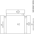
Figure 5 , prior artnon-volatile memory system 100 sometimes creates and maintainsprotected area 501 withinarray 101.Protected area 501 can then be used to store configuration data, trim data, fuses, and other types of data that are essential to the operation ofnon-volatile memory system 100, which will be referred to herein as "system data" or "system bits". User data will not be stored in protectedarea 501, and, optionally, protectedarea 501 is not accessible for read, erase, and program operations initiated from a source outside ofnon-volatile memory system 100. - Because the data stored in protected
area 501 is critical to the accurate functioning ofnon-volatile memory system 100, the data stored in protectedarea 501 needs extra protection from low-probability data loss events such as charge loss, charge movement, read disturb, radiation-induced soft errors, and other mechanisms which cause changes in the read current/voltage of a small fraction of the cells. - One prior art approach is to store each system bit in protected
area 501 in two non-volatile memory cells in a redundant fashion. In one approach, the read current from the two cells can be summed and compared against a reference value to determine the stored value. - However, even with redundancy, in some non-volatile memory cell designs, charge loss, charge redistribution, disturb, or other physical changes in the non-volatile memory cells will cause the cells to flip predominantly from a "1" state to "0" state, or from a "0" state to "1" state depending on the architecture of the non-volatile memory cell.
- This can corrupt the system bit. For example, if one of two non-volatile memory cells flips from a"0" state to a "1" state, the total read current will exceed the reference current, and the sensed data will flip from "0" to "1."
- What is needed is an embodiment for storing important system data in a non-volatile memory array so that the system data is less likely to become corrupted from charge loss, charge redistribution, disturb effects, or other physical changes in the non-volatile memory cell which cause a change in the read current or voltage, without limitation.
- Numerous embodiments are disclosed of improved architectures for storing and retrieving system data in a non-volatile memory system. Using these embodiments, system data is much less likely to become corrupted due to charge loss, charge redistribution, disturb effects, and other phenomena that have caused data corruption in prior art non-volatile memory systems.
- In one embodiment, a non-volatile memory system comprises an array of non-volatile memory cells arranged into rows and columns; a sense amplifier configured during a read operation to receive current from a first non-volatile memory cell in a first column of the array and to indicate a first value stored in the first non-volatile memory cell and to receive current from a second non-volatile memory cell in a second column of the array and to indicate a second value stored in the second non-volatile memory cell; and a logic circuit for receiving from the sense amplifier the first value and the second value and for generating a data bit output based on the first value and the second value.
- In another embodiment, a non-volatile memory system comprises an array of non-volatile memory cells arranged into rows and columns; and a sense amplifier configured during a read operation to receive combined current from a first non-volatile memory cell and a second non-volatile memory cell in a selected column of the array and to generate a data bit output indicating a value based on the combined current.
- In another embodiment, a non-volatile memory system, comprises an array of non-volatile memory cells arranged into rows and columns, each row comprising a word of non-volatile memory cells and error correction code data calculated from the word; a sense amplifier configured during a read operation to receive current from the array and to output a word and error correction code data for the word; and an error correction code engine for correcting one or more errors in the word using the error correction code data for the word.
-
-
Figure 1 depicts a prior art non-volatile memory system. -
Figure 2 depicts a prior art split gate flash memory cell. -
Figure 3 depicts another prior art split gate flash memory cell. -
Figure 4 depicts another prior art split gate flash memory cell. -
Figure 5 depicts a prior art non-volatile memory system with a protected area. -
Figure 6 depicts another embodiment of a system data architecture. -
Figure 7 depicts another embodiment of a system data architecture. -
Figure 8 depicts another embodiment of a system data architecture. -
Figure 9 depicts another embodiment of a system data architecture. -
Figure 10 depicts another embodiment of a system data architecture. -
Figure 11 depicts another embodiment of a system data architecture. -
Figures 6-8 depict embodiments that are particularly suitable for non-volatile memory (NVM) cell designs where a charge loss, charge redistribution, disturb, or other physical or electrical changes in the NVM cell will cause a cell to gravitate towards a "1" state, which might flip a stored "0" to a "1" but will not affect a stored "1". -
Figure 6 depictssystem data architecture 600. Each bit of system data is written into two redundant NVM cells, such ascells wordline 601, and in different columns accessible by different bit lines, such asbit lines - During a read operation, current from
NVM cells sense amplifier 104 against a reference current to determine their respective logic states. Data read from the two cells as output by sense amplifier 104 (which indicates a first value stored one of the twoNVM cells NVM cells 601, 602) are routed through AND device 603 (a logic device performing an AND function, which can be implemented using hardware logic or by firmware executed on a controller or processor) to generate the final system data (indicated by "Output"). - If
NVM cells NVM cells NVM cells device 603 will be "0". The probability of both NVM cells flipping from a "0" to a "1" is extremely low. - If
NVM cells NVM cells Bitline 606 andwordline 603 are shown for completeness. -
Figure 7 depictssystem data architecture 700. Each bit of system data is written into two redundant NVM cells. The redundant NVM cells each can be located in any row and in any column. That is, there is no restriction on where the redundant NVM cells can be placed, and they need not be located in the same row or column or adjacent rows or columns. In this example, a pair of redundant bits are stored inNVM cell 701 accessible bywordline 601 andbit line 604 and inNVM cell 702 accessible bywordline 603 andbitline 606.Bitline 602 andwordline 605 are shown for completeness. - During a read operation, current from
NVM cells sense amplifier 104 against a reference current to determine their respective logic states. Read data from the two NVM cells output by sense amplifier 104 (which indicates a first value stored one of the twoNVM cells NVM cells 701, 702) are processed with AND device 603 (a logic device performing an AND function, which can be implemented using hardware logic or by firmware executed on a controller or processor) to generate the final system data (indicated by "Output"). - If
NVM cells NVM cells NVM cells NVM cells - If
NVM cells -
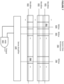
Figure 8 depictssystem data architecture 800. Each bit of system data is written into two redundant NVM cells, such asNVM cells bitline 604, but located in different rows accessible by different wordlines, such aswordlines Bitlines wordline 602 are shown for completeness. - During a read operation, both
wordlines NVM cells common bitline 604. The summed current is sensed bysense amplifier 104 against a reference current to determine its logic state. The reference current is set to a level within a range which is: higher than the sum of a typical 0-state read current for the NVM cells and the upper limit of a neutral floating gate (FG) read current (for NVM cells which use charge storage in a polysilicon FG, where the upper limit refers to the upper limit of the range of neutral FG read current for NVM cells in the array); or higher than the sum of typical 0-state read current plus the saturation point of 0-state read current movement (for NVM cells which use other storage mechanisms). The reference level is also lower than two times the lower limit of read current of 1-state cells which are read immediately after being set to 1-state. - During production test screen of a device following
system data architecture 800, a read with the reference current within the above mentioned range is performed on the protectedarea 501, to guarantee that the twoNVM cells - If the stored data in selected
NVM cells sense amplifier 104, (indicated by "Output") is still a "0". If the stored data in selected NVM calls 801 and 802 is "0", and one of the twoNVM cells sense amplifier 104 to be a "0". The probability of bothNVM cells - If
NVM cells NVM cells -
Figures 9-10 depict embodiments that are particularly suitable for NVM cell designs where a charge loss, charge redistribution, or disturb will cause a cell to gravitate towards a "0" state, which might flip a stored "1" to a "0" but will not affect a stored "0". -
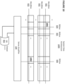
Figure 9 depictssystem data architecture 900. Each bit of system data is written into two redundant NVM cells, such ascells wordline 601, but located in different columns accessible by different bitlines, such asbitlines Bitline 606 andwordlines - During a read operation, current from
NVM cells sense amplifier 104 to determine a first value stored inNVM cell 901 and a second value stored inNVM 902. Read data from the two NVM cells output bysense amplifier 104 are processed with OR device 903 (a logic device performing an OR function, which can be implemented using hardware logic or by firmware executed on a controller or processor) to generate the final system data (indicated by "Output"). - If
NVM cells NVM cells device 903 will be "0". The probability of bothNVM cells - If
NVM cells NVM cells -
Figure 10 depictssystem data architecture 1000. Each bit of system data is written into two redundant NVM cells. The redundant NVM cells each can be located in any row and column. That is, there is no restriction on where the NVM cells can be placed, and they need not be located in the same row or column or adjacent rows or columns. - In this example, a pair of redundant bits are stored in
NVM cell 1001 accessible bywordline 601 andbit line 604 and inNVM cell 1002 accessible bywordline 603 andbitline 606.Bitline 605 andwordline 602 are shown for completeness. - During a read operation, current from
NVM cells sense amplifier 104 to determine a first value stored inNVM cell 1001 and a second value stored inNVM cell 1002. Read data from the two NVM cells output bysense amplifier 104 are processed with OR device 903 (a logic device performing an OR function, which can be implemented using hardware logic or by firmware executed on a controller or processor) to generate the final system data (indicated by "Output"). - If
NVM cells NVM cells device 903 will be "0". The probability of bothNVM cells - If
NVM cells NVM cells -
Figure 11 depicts an embodiment that is suitable for: (1) NVM cell designs where a charge loss, charge redistribution, disturb, or other physical changes to the cell will cause a cell to gravitate towards a "0" state, which might flip a stored "1" to a "0" but will not affect a stored "0"; (2) NVM cell designs where aforementioned changes will cause a cell to gravitate towards a "1" state, which might flip a stored "0" to a "1" but will not affect a stored "1"; and (3) NVM cell designs where aforementioned changes will cause an NVM cell to gravitate towards either state, which might flip some stored "0"s to "1"s but also might flip some stored "1"s to "0"s. -
Figure 11 depictssystem data architecture 1100. Here, each word of system data, such asword 1101, is stored with associated error correction code data, such as error correction code (ECC)data 1102 in a row. Each system bit is stored in a word and is stored without redundancy. Multiple words may be stored in a row, each with there associated error correction code data, without exceeding the scope. - Here,
ECC data 1102 is generated forword 1101 using an ECC, such as the Hamming code, or a code generated by the majority voter algorithm (where data is stored in N redundant physical cells and the value of the stored data is deemed to be the value indicated by a majority of the N cells), to perform error detection and error correction such as 2-bit error detection and 1-bit error correction scheme. In place ofECC data 1102, a parity bit scheme may be utilized to indicate error detection without correction. Whenbit 1101 is read, theentire word 1101 andECC data 1102 are read bysense amplifier 104 and sent toECC engine 1103. That is,sense amplifier 104 receives current from the array and outputs a word and error correction code data for the word toECC engine 1103. If any single bit inword 1101 has flipped in either direction, the error will be detected and/or corrected successfully byECC engine 1103. The probability of more than one bit flipping is extremely low. - In one embodiment,
system data architecture 1100 is additionally implemented with redundancy such as using multiple cells for each system bit to further enhance the reliability such as for functional safety for automotive applications. For example, each system bit can be stored in two cells in two rows or two columns, as described in previous embodiments. - In one embodiment,
ECC engine 1103 is implemented using an external controller or firmware. - It should be noted that, as used herein, the terms "over" and "on" both inclusively include "directly on" (no intermediate materials, elements or space disposed therebetween) and "indirectly on" (intermediate materials, elements or space disposed therebetween). Likewise, the term "adjacent" includes "directly adjacent" (no intermediate materials, elements or space disposed therebetween) and "indirectly adjacent" (intermediate materials, elements or space disposed there between), "mounted to" includes "directly mounted to" (no intermediate materials, elements or space disposed there between) and "indirectly mounted to" (intermediate materials, elements or spaced disposed there between), and "electrically coupled" includes "directly electrically coupled to" (no intermediate materials or elements there between that electrically connect the elements together) and "indirectly electrically coupled to" (intermediate materials or elements there between that electrically connect the elements together). For example, forming an element "over a substrate" can include forming the element directly on the substrate with no intermediate materials/elements therebetween, as well as forming the element indirectly on the substrate with one or more intermediate materials/elements there between.
- Further examples of the invention are given below:
- Example 1. A non-volatile memory system, comprising:
- an array of non-volatile memory cells arranged into rows and columns;
- a sense amplifier configured during a read operation to receive current from a first non-volatile memory cell in a first column of the array and to indicate a first value stored in the first non-volatile memory cell and to receive current from a second non-volatile memory cell in a second column of the array and to indicate a second value stored in the second non-volatile memory cell; and
- a logic circuit for receiving from the sense amplifier the indicated first value and the indicated second value and for generating a data bit output based on the indicated first value and the indicated second value.
- Example 2. The non-volatile memory system of example 1, wherein the first non-volatile memory cell and the second non-volatile memory cell are in the same row in the array.
- Example 3. The non-volatile memory system of example 2, wherein the logic circuit performs an AND operation on the first indicated value and the second indicated value to generate the data bit output.
- Example 4. The non-volatile memory system of example 2, wherein the logic circuit performs an OR operation on the first indicated value and the second indicated value to generate the data bit output.
- Example 5. The non-volatile memory system of example 1, wherein the first non-volatile memory cell and the second non-volatile memory cell are in different rows in the array.
- Example 6. The non-volatile memory system of example 5, wherein the logic circuit performs an AND operation on the first indicated value and the second indicated value to generate the data bit output.
- Example 7. The non-volatile memory system of example 5, wherein the logic circuit performs an OR operation on the first indicated value and the second indicated value to generate the data bit output.
- Example 8. A non-volatile memory system, comprising:
- an array of non-volatile memory cells arranged into rows and columns; and
- a sense amplifier configured during a read operation to receive combined current from a first non-volatile memory cell and a second non-volatile memory cell in a selected column of the array and to generate a data bit output indicating a value based on the combined current.
- Example 9. A non-volatile memory system, comprising:
- an array of non-volatile memory cells arranged into rows and columns, each row comprising a word of non-volatile memory cells and error correction code data calculated from the word;
- a sense amplifier configured during a read operation to receive current from the array and to output a word and error correction code data for the word; and
- an error correction code engine for correcting one or more errors in the word using the error correction code data for the word.
- Example 10. The non-volatile memory system of example 9, wherein the error correction code data for a word is generated using a Hamming code.
- Example 11. The non-volatile memory system of example 9, wherein the error correction code data for a word is generated using a majority voter algorithm.
Claims (4)
- A non-volatile memory system, comprising:an array of non-volatile memory cells arranged into rows and columns; anda sense amplifier configured during a read operation to receive combined current from a first non-volatile memory cell and a second non-volatile memory cell in a selected column of the array and to generate a data bit output indicating a value based on the combined current.
- A non-volatile memory system, comprising:an array of non-volatile memory cells arranged into rows and columns, each row comprising a word of non-volatile memory cells and error correction code data calculated from the word;a sense amplifier configured during a read operation to receive current from the array and to output a word and error correction code data for the word; andan error correction code engine for correcting one or more errors in the word using the error correction code data for the word.
- The non-volatile memory system of claim 2, wherein the error correction code data for a word is generated using a Hamming code.
- The non-volatile memory system of claim 2, wherein the error correction code data for a word is generated using a majority voter algorithm.
Applications Claiming Priority (4)
| Application Number | Priority Date | Filing Date | Title |
|---|---|---|---|
| US202063131624P | 2020-12-29 | 2020-12-29 | |
| US17/199,383 US11538532B2 (en) | 2020-12-29 | 2021-03-11 | Architectures for storing and retrieving system data in a non-volatile memory system |
| EP21720891.7A EP4272214B1 (en) | 2020-12-29 | 2021-03-30 | Improved architectures for storing and retrieving system data in a non-volatile memory system |
| PCT/US2021/025009 WO2022146465A1 (en) | 2020-12-29 | 2021-03-30 | Improved architectures for storing and retrieving system data in a non-volatile memory system |
Related Parent Applications (2)
| Application Number | Title | Priority Date | Filing Date |
|---|---|---|---|
| EP21720891.7A Division EP4272214B1 (en) | 2020-12-29 | 2021-03-30 | Improved architectures for storing and retrieving system data in a non-volatile memory system |
| EP21720891.7A Division-Into EP4272214B1 (en) | 2020-12-29 | 2021-03-30 | Improved architectures for storing and retrieving system data in a non-volatile memory system |
Publications (2)
| Publication Number | Publication Date |
|---|---|
| EP4579462A2 true EP4579462A2 (en) | 2025-07-02 |
| EP4579462A3 EP4579462A3 (en) | 2026-01-21 |
Family
ID=82118995
Family Applications (2)
| Application Number | Title | Priority Date | Filing Date |
|---|---|---|---|
| EP21720891.7A Active EP4272214B1 (en) | 2020-12-29 | 2021-03-30 | Improved architectures for storing and retrieving system data in a non-volatile memory system |
| EP25176395.9A Pending EP4579462A3 (en) | 2020-12-29 | 2021-03-30 | Improved architectures for storing and retrieving system data in a non-volatile memory system |
Family Applications Before (1)
| Application Number | Title | Priority Date | Filing Date |
|---|---|---|---|
| EP21720891.7A Active EP4272214B1 (en) | 2020-12-29 | 2021-03-30 | Improved architectures for storing and retrieving system data in a non-volatile memory system |
Country Status (6)
| Country | Link |
|---|---|
| US (1) | US11538532B2 (en) |
| EP (2) | EP4272214B1 (en) |
| JP (1) | JP7654797B2 (en) |
| KR (1) | KR20230080482A (en) |
| CN (1) | CN116569257A (en) |
| TW (2) | TWI803079B (en) |
Families Citing this family (1)
| Publication number | Priority date | Publication date | Assignee | Title |
|---|---|---|---|---|
| US11847021B2 (en) * | 2022-02-25 | 2023-12-19 | Macronix International Co., Ltd. | Memory block, memory device for error correction operation and method thereof |
Citations (2)
| Publication number | Priority date | Publication date | Assignee | Title |
|---|---|---|---|---|
| US5029130A (en) | 1990-01-22 | 1991-07-02 | Silicon Storage Technology, Inc. | Single transistor non-valatile electrically alterable semiconductor memory device |
| US7868375B2 (en) | 2007-08-06 | 2011-01-11 | Silicon Storage Technology, Inc. | Split gate non-volatile flash memory cell having a floating gate, control gate, select gate and an erase gate with an overhang over the floating gate, array and method of manufacturing |
Family Cites Families (19)
| Publication number | Priority date | Publication date | Assignee | Title |
|---|---|---|---|---|
| US4519079A (en) * | 1983-02-17 | 1985-05-21 | The United States Of America As Represented By The Secretary Of The Army | Error correction method and apparatus |
| US4748594A (en) | 1984-11-12 | 1988-05-31 | Nec Corporation | Integrated circuit device having a memory and majority logic |
| JP2001043691A (en) | 1999-07-28 | 2001-02-16 | Hitachi Ltd | Nonvolatile storage circuit and microcomputer |
| US6941505B2 (en) | 2000-09-12 | 2005-09-06 | Hitachi, Ltd. | Data processing system and data processing method |
| JP4066308B2 (en) * | 2001-11-05 | 2008-03-26 | 松下電器産業株式会社 | Semiconductor memory device and data processing device |
| US6687162B1 (en) * | 2002-04-19 | 2004-02-03 | Winbond Electronics Corporation | Dual reference cell for split-gate nonvolatile semiconductor memory |
| JP2005085316A (en) | 2003-09-05 | 2005-03-31 | Renesas Technology Corp | Nonvolatile semiconductor memory |
| JP4469649B2 (en) | 2003-09-17 | 2010-05-26 | 株式会社ルネサステクノロジ | Semiconductor flash memory |
| EP1912121B1 (en) * | 2006-09-13 | 2009-08-12 | STMicroelectronics S.r.l. | NAND flash memory device with ECC protected reserved area for non volatile storage of redundancy data |
| JP2009199695A (en) * | 2008-02-25 | 2009-09-03 | Toshiba Corp | Resistance change memory device |
| JP2010277662A (en) | 2009-05-29 | 2010-12-09 | Elpida Memory Inc | Semiconductor device and manufacturing method thereof |
| JP2011090735A (en) | 2009-10-21 | 2011-05-06 | Asahi Kasei Electronics Co Ltd | Memory device and data processing method of the memory device |
| US9019771B2 (en) * | 2012-10-26 | 2015-04-28 | Macronix International Co., Ltd. | Dielectric charge trapping memory cells with redundancy |
| TWI573148B (en) * | 2013-08-02 | 2017-03-01 | 東芝股份有限公司 | A controller, a memory system, and a memory device |
| US9842021B2 (en) * | 2015-08-28 | 2017-12-12 | Intel Corporation | Memory device check bit read mode |
| US9589604B1 (en) * | 2015-09-17 | 2017-03-07 | International Business Machines Corporation | Single ended bitline current sense amplifier for SRAM applications |
| US20180336139A1 (en) | 2017-05-16 | 2018-11-22 | Sandisk Technologies Llc | Systems and methods for a highly-available memory |
| US10403357B2 (en) * | 2017-09-18 | 2019-09-03 | Nxp Usa, Inc. | Resistive non-volatile memory and a method for sensing a memory cell in a resistive non-volatile memory |
| KR102629405B1 (en) * | 2018-11-09 | 2024-01-25 | 삼성전자주식회사 | Memory devices, memory systems and methods of operating memory devices |
-
2021
- 2021-03-11 US US17/199,383 patent/US11538532B2/en active Active
- 2021-03-30 EP EP21720891.7A patent/EP4272214B1/en active Active
- 2021-03-30 EP EP25176395.9A patent/EP4579462A3/en active Pending
- 2021-03-30 KR KR1020237015476A patent/KR20230080482A/en not_active Ceased
- 2021-03-30 CN CN202180083662.8A patent/CN116569257A/en active Pending
- 2021-03-30 JP JP2023539289A patent/JP7654797B2/en active Active
- 2021-12-01 TW TW110144765A patent/TWI803079B/en active
- 2021-12-01 TW TW112114169A patent/TWI892114B/en active
Patent Citations (2)
| Publication number | Priority date | Publication date | Assignee | Title |
|---|---|---|---|---|
| US5029130A (en) | 1990-01-22 | 1991-07-02 | Silicon Storage Technology, Inc. | Single transistor non-valatile electrically alterable semiconductor memory device |
| US7868375B2 (en) | 2007-08-06 | 2011-01-11 | Silicon Storage Technology, Inc. | Split gate non-volatile flash memory cell having a floating gate, control gate, select gate and an erase gate with an overhang over the floating gate, array and method of manufacturing |
Also Published As
| Publication number | Publication date |
|---|---|
| TW202331725A (en) | 2023-08-01 |
| EP4272214A1 (en) | 2023-11-08 |
| EP4579462A3 (en) | 2026-01-21 |
| US20220208277A1 (en) | 2022-06-30 |
| US11538532B2 (en) | 2022-12-27 |
| JP2024501836A (en) | 2024-01-16 |
| EP4272214B1 (en) | 2025-06-25 |
| TW202232495A (en) | 2022-08-16 |
| TWI892114B (en) | 2025-08-01 |
| CN116569257A (en) | 2023-08-08 |
| TWI803079B (en) | 2023-05-21 |
| KR20230080482A (en) | 2023-06-07 |
| JP2025102826A (en) | 2025-07-08 |
| JP7654797B2 (en) | 2025-04-01 |
Similar Documents
| Publication | Publication Date | Title |
|---|---|---|
| EP4026129B1 (en) | Method of improving read current stability in analog non-volatile memory by screening memory cells | |
| KR101368375B1 (en) | Erased sector detection mechanisms | |
| TWI286754B (en) | Algorithm dynamic reference programming | |
| KR100992985B1 (en) | Flash storage system with write / erase interrupt detection mechanism | |
| US20190303236A1 (en) | Multi-level recovery reads for memory | |
| US7151692B2 (en) | Operation scheme for programming charge trapping non-volatile memory | |
| TWI498919B (en) | Method and apparatus for programming memory cell array | |
| TW201511024A (en) | Efficient post write read in three dimensional nonvolatile memory | |
| TW201503138A (en) | Selection of data for redundancy calculation in three dimensional nonvolatile memory | |
| JP3079370B2 (en) | Non-volatile memory device | |
| US20050237842A1 (en) | Semiconductor integrated circuit device | |
| US20040125655A1 (en) | Non-volatile memory and operating method thereof | |
| EP4272214B1 (en) | Improved architectures for storing and retrieving system data in a non-volatile memory system | |
| EP4352728B1 (en) | Method of reducing random telegraph noise in non-volatile memory by grouping and screening memory cells | |
| US6934190B1 (en) | Ramp source hot-hole programming for trap based non-volatile memory devices | |
| US7457144B2 (en) | Memory device and method for verifying information stored in memory cells | |
| WO2022146465A1 (en) | Improved architectures for storing and retrieving system data in a non-volatile memory system | |
| JP7863228B2 (en) | An improved architecture for storing and retrieving system data in a non-volatile memory system. | |
| CN100449646C (en) | Programming method and apparatus for non-volatile memory | |
| US20040264253A1 (en) | Non-volatile semiconductor memory device and erasing control method thereof | |
| US12229004B2 (en) | Grouping and error correction for non-volatile memory cells | |
| JP3576686B2 (en) | Nonvolatile semiconductor memory device | |
| JP2000149574A (en) | New flash memory array and decoding structure |
Legal Events
| Date | Code | Title | Description |
|---|---|---|---|
| PUAI | Public reference made under article 153(3) epc to a published international application that has entered the european phase |
Free format text: ORIGINAL CODE: 0009012 |
|
| STAA | Information on the status of an ep patent application or granted ep patent |
Free format text: STATUS: THE APPLICATION HAS BEEN PUBLISHED |
|
| AC | Divisional application: reference to earlier application |
Ref document number: 4272214 Country of ref document: EP Kind code of ref document: P |
|
| AK | Designated contracting states |
Kind code of ref document: A2 Designated state(s): AL AT BE BG CH CY CZ DE DK EE ES FI FR GB GR HR HU IE IS IT LI LT LU LV MC MK MT NL NO PL PT RO RS SE SI SK SM TR |
|
| REG | Reference to a national code |
Ref country code: DE Ref legal event code: R079 Free format text: PREVIOUS MAIN CLASS: G06F0011100000 Ipc: G11C0007100000 |
|
| PUAL | Search report despatched |
Free format text: ORIGINAL CODE: 0009013 |
|
| AK | Designated contracting states |
Kind code of ref document: A3 Designated state(s): AL AT BE BG CH CY CZ DE DK EE ES FI FR GB GR HR HU IE IS IT LI LT LU LV MC MK MT NL NO PL PT RO RS SE SI SK SM TR |
|
| RIC1 | Information provided on ipc code assigned before grant |
Ipc: G11C 7/10 20060101AFI20251218BHEP Ipc: G11C 5/00 20060101ALI20251218BHEP Ipc: G11C 7/08 20060101ALI20251218BHEP Ipc: G11C 7/02 20060101ALI20251218BHEP Ipc: G06F 11/10 20060101ALI20251218BHEP Ipc: G11C 11/56 20060101ALI20251218BHEP |