EP4579364A1 - A method for controlling a planar motor system, a computer program product for actuating the method, a planar motor system and an handling apparatus comprising the planar motor system - Google Patents
A method for controlling a planar motor system, a computer program product for actuating the method, a planar motor system and an handling apparatus comprising the planar motor system Download PDFInfo
- Publication number
- EP4579364A1 EP4579364A1 EP24219883.6A EP24219883A EP4579364A1 EP 4579364 A1 EP4579364 A1 EP 4579364A1 EP 24219883 A EP24219883 A EP 24219883A EP 4579364 A1 EP4579364 A1 EP 4579364A1
- Authority
- EP
- European Patent Office
- Prior art keywords
- carrier
- points
- base element
- movement
- carriers
- Prior art date
- Legal status (The legal status is an assumption and is not a legal conclusion. Google has not performed a legal analysis and makes no representation as to the accuracy of the status listed.)
- Pending
Links
Images




Classifications
-
- G—PHYSICS
- G05—CONTROLLING; REGULATING
- G05B—CONTROL OR REGULATING SYSTEMS IN GENERAL; FUNCTIONAL ELEMENTS OF SUCH SYSTEMS; MONITORING OR TESTING ARRANGEMENTS FOR SUCH SYSTEMS OR ELEMENTS
- G05B19/00—Program-control systems
- G05B19/02—Program-control systems electric
- G05B19/418—Total factory control, i.e. centrally controlling a plurality of machines, e.g. direct or distributed numerical control [DNC], flexible manufacturing systems [FMS], integrated manufacturing systems [IMS] or computer integrated manufacturing [CIM]
- G05B19/4189—Total factory control, i.e. centrally controlling a plurality of machines, e.g. direct or distributed numerical control [DNC], flexible manufacturing systems [FMS], integrated manufacturing systems [IMS] or computer integrated manufacturing [CIM] characterised by the transport system
-
- G—PHYSICS
- G05—CONTROLLING; REGULATING
- G05B—CONTROL OR REGULATING SYSTEMS IN GENERAL; FUNCTIONAL ELEMENTS OF SUCH SYSTEMS; MONITORING OR TESTING ARRANGEMENTS FOR SUCH SYSTEMS OR ELEMENTS
- G05B19/00—Program-control systems
- G05B19/02—Program-control systems electric
- G05B19/18—Numerical control [NC], i.e. automatically operating machines, in particular machine tools, e.g. in a manufacturing environment, so as to execute positioning, movement or co-ordinated operations by means of program data in numerical form
- G05B19/406—Numerical control [NC], i.e. automatically operating machines, in particular machine tools, e.g. in a manufacturing environment, so as to execute positioning, movement or co-ordinated operations by means of program data in numerical form characterised by monitoring or safety
- G05B19/4061—Avoiding collision or forbidden zones
Definitions
- exclusion areas are non-limiting examples; it is understood that the exclusion area could also be defined by other elements.
- the method comprises generating the graph G and calculating the movement path P according to a Dijkstra algorithm.
- the invention concerns a planar motor system 1, comprising:
- control unit 4 is configured for controlling the movement of the carriers 3A,3B,3C,3D over the base element 2.
- system 1 planar motor system
- control unit 4 is configured for detecting, or receiving, one or more signals indicative of an event related to the functioning of the carriers 3A,3B,3C,3D and/or of the base element 2.
- the term "event” encompasses various occurrences, including but not limited to, signal reception and/or changes in the configuration of control unit 4, changing on the number of carriers or in the number or location of the processing station, among others.
- the events may be related to operation of the base element, the carriers and/or the packaging line.
- control unit 4 is configured to move (i.e. drive) each carrier 3A, 3B, 3C, 3D over the base element 2, preferably along two orthogonal directions (lying on the base element 2) and in height relative to the base element 2.
- control unit 4 is configured to rotate each carrier 3A, 3B, 3C, 3D at least partially over the base element 2, preferably around three orthogonal independent axes (one of which being orthogonal to a surface of the base element 2).
- the base element is magnetizable.
- the base element 2 comprises a plurality of coils (not shown) which can be selectively activated in a known manner to generate an electromagnetic field able to move the carriers 3A, 3B, 3C, 3D over the base element 2.
- control unit 4 is configured (e.g. by means of the computer program executed therein) for:
- the starting point P1 and the arrival point P2 may vary depending on the specific type of event, as will be elaborated upon in more detail later.
- different event signals may be related to different starting points P1 and arrival points P2.
- the movement path P from the starting point P1 to the arrival point P2 is calculated based on the detected event, as will be further disclosed later.
- control unit 4 is configured for calculating the path P from the starting point P1 to the arrival point P2, which include at least a transit point TP.
- the transit point TP is a point wherein the carrier 3A,3B,3C,3D should at least pass.
- the carrier may stop at least temporarily at the transit point TP.
- the transit point TP is one of the potential movement points of the graph G.
- the transit points TP may be indicative of a presence of respective handling stations, e.g. designated areas in the system wherein loading, unloading, processing, or manipulation of containers or products take place.
- the transit points TP could be, for example, one or more processing stations 9 such as a printing station or a capping station, a feeding conveyor 7, a discharge conveyor 8, etc.
- transit points TP due to the presence of transit points TP, it is possible to generate a movement path P that enables the carriers 3A,3B,3C,3D to pass precisely through desired points (i.e. transit point TP) where certain operations are performed, such as product reception or product processing, and so on.
- control unit 4 is configured (thanks to the computer program loaded and executed) for calculating the graph G excluding, from the plurality of potential movement points, points belonging to at least an excluded area EA over the base element 2.
- this allows for the exclusion of points from the movement path P where, for example, obstacles are present (which can be any objects or elements on the base element 2 that may hinder the free movement of carriers 3A, 3B, 3C, 3D).
- the excluded area comprises, for each carrier 3A,3B,3C,3D, the regions over the base element 2 wherein the other carriers 3A,3B,3C,3D are located.
- the region of the base element 2 occupied by a specific carrier 3A, 3B, 3C, 3D defines an excluded area for the other carriers 3A, 3B, 3C, 3D, thereby preventing collisions among carriers 3A, 3B, 3C, 3D when defining their paths following an event.
- control unit 4 is configured to calculate the graph G and the movement path P according to a Dijkstra algorithm.
- the starting point P1 corresponds to the current position of each carrier 3A, 3B, 3C, 3D
- the arrival point P2 is a predefined home position for each carrier 3A, 3B, 3C, 3D.
- the arrival point P2 (i.e. the home position) is distinct for each carrier 3A, 3B, 3C, 3D.
- the starting point P1 is different for each carrier 3A, 3B, 3C, 3D and corresponds to the instant position of the carrier (preferably at the time the event is detected or triggered).
- control unit 4 is configured to sequentially move one carrier 3A, 3B, 3C, 3D at a time along the calculated path P.
- the calculation of the movement path P is simplified because the excluded zones EA for the movement of a carrier 3A, 3B, 3C, 3D, corresponding to the instantaneous positions of the other carriers 3A, 3B, 3C, 3D, are not dynamic (i.e., subject to change over time due to the simultaneous motion of multiple carriers 3A, 3B, 3C, 3D) but rather static. Therefore, the control unit 4 (by means of the computer program executed therein) calculates the movement path P for a carrier 3A, 3B, 3C, 3D while considering the other carriers 3A, 3B, 3C, 3D as stationary or maintaining their position over the base element 2.
- the event represents a change in the number of the carriers 3A,3B,3C,3D, operating over the base element 2.
- the event corresponds to the movement or change in the number of a transit point TP (preferably corresponding to a processing station) above the base element 2.
- the control unit 4 performs a graph and movement path calculation for the corresponding number of carriers 3A, 3B, 3C, 3D operating over the base element 2 to optimize the trajectories of individual carriers 3A, 3B, 3C, 3D as a result of the variation in the number and/or position of the transit point TP.
- the control unit 4 is configured (by means of the computer program executed therein) to generate a graph G defined by a plurality of potential movement points over the base element 2, including the starting point P1 and the arrival point P2.
- control unit 4 (by means of the computer program executed therein) generates, according to predetermined rules, the potential movement points defining the graph G.
- each point is connected only to adjacent points along predetermined directions. Such connection is also called “edge”, whilst each point of the graph G is also called a “node”.
- the graph G is generated as follows.
- control unit 4 (by means of the computer program executed therein which operates the disclosed controlling method) is configured to determine a plurality of potential movement points defining the graph G, both horizontally and vertically relative to the edges of the base element 2.
- the starting point P1 is the center of a carrier 3A,3B,3C,3D (in Figure 3 , the starting point of carrier 3A has been labeled as P1A).
- a grid of potential movement points is constructed along two orthogonal directions, D1 and D2, each of which is parallel to a different side of the orthogonal sides of the base element 2.
- the direction D1 will hereafter be referred to as the horizontal direction, while the direction D2 will be referred to as the vertical direction.
- these potential movement points are located horizontally at least half the horizontal length of the carrier 3A, 3B, 3C, 3D. Additionally, they are positioned vertically at least half the vertical length of the carrier 3A, 3B, 3C, 3D.
- These potential movement points are spaced from each other at a predetermined interval, which may differ in the D1 direction compared to the D2 direction.
- the interval or distance between the potential movement points in the D1 direction is equal to or greater than the length L1 of the carrier in that direction.
- the interval or distance between the potential movement points in the D2 direction is equal to or greater than the length L2 of the carrier in that direction.
- control unit 4 has a memory 10 containing predetermined weight values for at least a portion of the adjacent feasible movement points in the graph G.
- the control unit 4 (by means of the computer program executed therein which actuates the disclosed controlling method) is configured to set a predetermined weight (e.g. a low weight, in the case of a path calculation function that minimize the sum of weights). Additionally, the control unit 4 is configured (by means of the computer program executed therein which actuates the disclosed controlling method) to set predetermined weights for points within the transit point TP. This way, advantageously, the control unit 4 calculates the movement path to ensure it passes through the desired transit point TP.
- a predetermined weight e.g. a low weight, in the case of a path calculation function that minimize the sum of weights.
- the predetermined weight values represent the distances, meaning they are positively correlated with the distance between adjacent feasible moving points in the graph G.
- the calculated path P from the starting point P1 to the arrival point P2 corresponds to the path that minimizes the overall distance between the starting point P1 and the arrival point P2. In other words, this path optimizes (minimizes) the conveying time of the carrier 3A, 3B, 3C, 3D.
- control unit 4 has predetermined preferential weight values for some points of the potential movement points over the base element 2, different for each carrier 3A,3B,3C,3D, the predetermined preferential weight values defining preferential path for each carrier 3A,3B,3C,3D.
- control unit 4 can be configured (by means of the computer program executed therein which operates the disclosed controlling method) to assign weight values to diagonal edges that differ from the weight values assigned to vertical or horizontal edges.
- control unit 4 (by means of the computer program executed therein which operates the disclosed controlling method) is configured to assign different weights values to trajectories with different inclinations.
- control unit 4 could be configured (by means of the computer program executed therein which operates the disclosed controlling method) to calculate the speed of a carrier 3A,3B,3C,3D along each edge (connection) of the movement path P based on the weight value of the same edge.
- control unit 4 is configured to assign a movement speed to each carrier 3A, 3B, 3C, 3D on a single edge based on the weight value.
- the first carrier 3A needs to be moved to position P2, which is commonly referred to as the home position.
- Figure 4 represents the movement path P calculated by the control unit 4 between the starting position P1 and the arrival position P2. It is worth noting that this movement path P is the shortest distance path between the starting position P1 and the arrival position P2.
- Figure 5 represents the graph G related to carrier 3B.
- the interpolated portion may comprise the portion whereby the carrier 3A,3B,3C,3D carries an object.
- each carrier 3A, 3B, 3C, 3D there is no deceleration/acceleration of each carrier 3A, 3B, 3C, 3D between one point and the next, as would occur in the case of a number of discrete points comprising the movement path P. Under this scenario, the speed of each carrier 3A,3B,3C,3D remains more constant.
- the mathematical function is a spline function interpolating said portion of the potential movement points of the graph G.
- a spline is a mathematical curve that is defined by a set of control points (i.e. the portion of the potential movement points of the graph G defining the movement path P from the starting point P1 to the arrival point P2).
- control unit 4 comprises an interface unit 6, configured for receiving an event signal.
- control unit 4 is configured for detecting, or receiving information concerning, an event relative to the functioning of the carriers 3A, 3B, 3C, 3D and / or of the base element 2 based on such event signal.
- detecting an event refers to the fact that the control unit 4, through issued commands, sensors, or signals, is instructed that a change in operating conditions has occurred.
- the interface unit can comprise a wi-fi module or an electric connector having inputs or outputs or commands (buttons, touch screen, a receiver for vocal commands, etc.).
- the control unit 4 could be the control unit of a packaging line, such as a PLC or defined by any computerized means (even remote) which can carry out the method according to the invention.
- the event signal could be the signal from the packaging line's control unit.
- planar motor system 1 and the method according to the invention allows for a reduction in collisions between carriers 3A, 3B, 3C, 3D and optimizes their trajectories.
- calculating the trajectory, specifically the movement path P, using a graph G allows for the reduction of any collision risks. This is achieved through precise calculations of the paths taken by the different carriers 3A, 3B, 3C, 3D, with the aim of avoiding collisions between them.
- an apparatus 11 for handling products PR comprising:
- the apparatus 11 further comprises:
- the apparatus 11 for handling products PR is part of a packaging line, which is not illustrated.
Landscapes
- Engineering & Computer Science (AREA)
- General Engineering & Computer Science (AREA)
- Manufacturing & Machinery (AREA)
- Quality & Reliability (AREA)
- Physics & Mathematics (AREA)
- General Physics & Mathematics (AREA)
- Automation & Control Theory (AREA)
- Control Of Position, Course, Altitude, Or Attitude Of Moving Bodies (AREA)
- Control Of Conveyors (AREA)
Abstract
It is disclosed a method for controlling a planar motor system (1), the planar motor system (1) comprising a base element (2) and a plurality of carriers (3A,3B,3C,3D), movable independently over the base element (2);
the method comprising the following phases:
- receiving an event signal indicative an event related to the operation of the carriers (3A,3B,3C,3D) and / or of the base element (2),
and performing the following operation, as a function of the event signal:
- determining, for each carrier (3A,3B,3C,3D), a starting point (P1) and an arrival point (P2),
- generating a graph (G) defined by a plurality of potential movement points over the base element (2), including the starting point (P1) and the arrival point (P2),
- calculating a movement path (P) from the starting point (P1) to the arrival point (P2), which connects a portion of the potential movement points of the graph (G) .
the method comprising the following phases:
- receiving an event signal indicative an event related to the operation of the carriers (3A,3B,3C,3D) and / or of the base element (2),
and performing the following operation, as a function of the event signal:
- determining, for each carrier (3A,3B,3C,3D), a starting point (P1) and an arrival point (P2),
- generating a graph (G) defined by a plurality of potential movement points over the base element (2), including the starting point (P1) and the arrival point (P2),
- calculating a movement path (P) from the starting point (P1) to the arrival point (P2), which connects a portion of the potential movement points of the graph (G) .
Description
- The present invention relates to a planar motor system and to a method for operating such planar motor system, which planar motor system could be advantageously employed as a part of a product handling apparatus for a packaging line.
- As it is commonly understood, numerous liquid or pourable food products are distributed in containers that are manufactured within a packaging production line, notably through the utilization of a packaging apparatus. Conventionally, after their production, these containers are subsequently transported to specific operational stations, such as those designed for sealing or for conducting additional procedures on the same container.
- Planar motor systems have been established for the conveyance of diverse product types. Conventionally, a planar motor system comprises a base element and an array of carriers that move over the base element. These carriers possess the capability to traverse along two principal axes, specifically the x-axis and the y-axis, and their relative elevation concerning the base element can be modulated along the z-axis.
- Furthermore, these carriers are equipped with the capacity for full rotation about an axis orthogonal to the base element, i.e., the z-axis, and can be rotated along two additional axes parallel to both the x-axis and the y-axis, albeit within a constrained angular range.
- Such planar motor systems are controlled by a control unit, which operates on the base element to move or rotate, individually, each of the carrier in order to execute the assigned task.
- Such planar motor systems could be advantageously employed downstream to a packaging machine, for carrying out operation on the produced container.
- In the context of normal operation, various events can occur that may affect the functioning of the planar motor system.
- For example, it can occur that the control unit of the planar motor system is susceptible to errors, which may also arise from circumstances occurring on individual carriers, such as the application of excessive force that the magnet cannot compensate for or other factors.
- In such situations, since the upstream packaging machine operates at a constant speed, it is imperative to promptly restore the operability of the planar motor system to prevent production stoppages or the rejection of containers.
- Hence, a need exists for a planar motor system that can operate optimally regardless of circumstances and can rapidly restore its functionality, for instance in cases of malfunctions or changes in the operational configuration.
- Furthermore, there is a particularly strong need to have at one's disposal a planar motor system in which collisions between different carriers are substantially avoided.
- There is a highly recognized need in the relevant sector to have access to a planar motor system that can operate efficiently and safely under all circumstances and can adapt very quickly to events or changes that may occur during operation.
- One objective of the present invention is therefore to make available a planar motor system and a control method that can, advantageously, rapidly and flexibly adapt to events or changes that occur in its operation, minimizing the risk of collisions between carriers.
- The advantages of the invention will be more conspicuously evident in the ensuing detailed description, accompanied by reference to the appended drawings, which represent a purely exemplary and non-limiting embodiment, wherein:
-
Figure 1 provides a schematic top view of the planar motor system according to the invention, which is used in a product handling apparatus. -
Figure 2 offers a schematic top view of the planar motor system according to the invention, also employed in a product handling apparatus. -
Figures 3 to 5 schematically represent a graph traced over a base element of the planar motor system according to the invention. - The invention concerns a method for controlling a planar motor system 1 comprising a
base element 2 and a plurality ofcarriers base element 2. - The method comprises receiving an event signal indicative of an event related to the operation of the
carriers base element 2, and performs the following steps, as a function of the event signal: - determining, for each
carrier - generating a graph G defined by a plurality of potential movement points over the
base element 2, including the starting point P1 and the arrival point P2, - calculating, for each carrier, a movement path P from the starting point P1 to the arrival point P2 comprising a portion of the potential movement points of the graph G,
- driving the plurality of
carriers - In the following, further aspects of the invention will be disclosed, which could be each other combined.
- According to one aspect, the method comprises driving the plurality of
carriers base element 2, including predetermined starting points and predetermined arrival points for eachcarrier - In accordance with this aspect, the method involves moving
carriers - According to another aspect, the method comprises identifying a number of transit points TP indicative of a presence of respective handling stations, and calculating, for each carrier, the movement path P from the starting point P1 to the arrival point P2 also as a function of at least a transit point TP.
- Note that, in accordance with this aspect,
carriers - According to another aspect, the event signal is indicative of a variation in the number of
carriers base element 2. - Thus, following the above event signal, indicative of a variation in the number of
carriers base element 2, the method further comprising the following phases: - adjusting a number of transit points TP and/or exclusion areas EA based on the event signal indicative of a variation in the number of
operative carriers - adjusting the movement path P of the
carriers - This advantageously allows adapting the movement path of
carriers - According to a further aspect, the method comprises:
- identifying a number of excluded areas EA on the
base element 2 indicative of obstacles for at least one carrier in the plurality ofcarriers - calculating the graph G excluding, from the plurality of potential movement points, points belonging to the excluded areas EA of the
base element 2. - According to a further aspect, the excluded area EA comprises at least one of:
- for each
carrier base element 2 where theother carriers - obstacles present at the
base element 2 hindering the movement of thecarrier carrier - an area proximate to the borders of the
base element 2; - a safety area surrounding each
carrier - The previously defined examples of exclusion areas (EA) are non-limiting examples; it is understood that the exclusion area could also be defined by other elements.
- According to a still further aspect, the method comprises generating the graph G and calculating the movement path P according to a Dijkstra algorithm.
- According to another aspect, the event signal is indicative of an error condition, and wherein the phase of determining, for each
carrier carrier carrier - This scenario will be further described below.
- According to a different aspect of the method:
- the calculated movement path P from the starting point P1 to the arrival point P2 corresponds to the movement path, among the plurality of feasible moving points, which optimizes the sum of predetermined weight values associated to each connection between adjacent feasible moving points in the graph G;
- the predetermined weight values represent the distances between adjacent feasible moving points in the graph G;
- the calculated path P from the starting point P1 to the arrival point P2 corresponding to the path which minimizes the overall distance from the starting point P1 and the arrival point P2.
- According to an aspect of the method, the calculated path P from the starting point P1 to the arrival point P2 corresponds to the path, among the plurality of feasible moving points, which optimizes the sum of predetermined weight values associated to each connection between adjacent feasible moving points in the graph G and wherein the predetermined preferential weight values for some points of the potential movement points over the
base element 2 are different for eachcarrier carrier - According to a further aspect, the method comprises interpolating at least partly the portion of the potential movement points of the movement path, thereby reducing the number of movement points of the movement path.
- Further, the interpolated points comprise points whereby the carrier has a constant speed and/or a rectilinear path and/or whereby the
carrier - According to another aspect, the method comprises interpolating at least partly said portion of the potential movement points by means of a spline function.
- According to the invention, it is further disclosed a computer program product, loadable in a memory of at least one control unit, and comprising software code portions suitable for performing the phases of the method for controlling a planar motor system as disclosed.
- The invention concerns a planar motor system 1, comprising:
- a
base element 2; - a plurality of
carriers base element 2; - a
control unit 4 configured to perform the steps of the method herein described. - Preferably, the
control unit 4 is configured for controlling the movement of thecarriers base element 2. - In the subsequent discussion, a comprehensive disclosure of the planar motor system (referred to as "system 1") will be presented in intricate detail. It is to be understood that the particulars and aspects elucidated concerning the planar motor system 1 are equally applicable to the disclosed method.
- The computer program product previously introduced may be loaded in and executed by the
control unit 4. According to the invention, thecontrol unit 4 is configured for detecting, or receiving, one or more signals indicative of an event related to the functioning of thecarriers base element 2. - In the current description, the term "event" encompasses various occurrences, including but not limited to, signal reception and/or changes in the configuration of
control unit 4, changing on the number of carriers or in the number or location of the processing station, among others. The events may be related to operation of the base element, the carriers and/or the packaging line. - According to another aspect, the
control unit 4 is configured to move (i.e. drive) eachcarrier base element 2, preferably along two orthogonal directions (lying on the base element 2) and in height relative to thebase element 2. - Furthermore, according to another aspect, the
control unit 4 is configured to rotate eachcarrier base element 2, preferably around three orthogonal independent axes (one of which being orthogonal to a surface of the base element 2). - Preferably, the base element is magnetizable. According to this aspect, the
base element 2 comprises a plurality of coils (not shown) which can be selectively activated in a known manner to generate an electromagnetic field able to move thecarriers base element 2. - According to the description, the
control unit 4 is configured (e.g. by means of the computer program executed therein) for: - determining, for each
carrier - generating a graph G defined by a plurality of potential movement points over the
base element 2, including the starting point P1 and the arrival point P2, as a function of the detected event; - calculating a movement path P from the starting point P1 to the arrival point P2, which connects a portion of the potential movement points of the graph G, as a function of the detected event;
- driving the plurality of
carriers - Please take into consideration that the calculations or determination or generation mentioned above are performed by the
control unit 4, relying on the detected event. - For instance, the starting point P1 and the arrival point P2 may vary depending on the specific type of event, as will be elaborated upon in more detail later.
- In other words, different event signals may be related to different starting points P1 and arrival points P2.
- Further, the movement path P from the starting point P1 to the arrival point P2 is calculated based on the detected event, as will be further disclosed later.
- According to another aspect, the
control unit 4 is configured for calculating the path P from the starting point P1 to the arrival point P2, which include at least a transit point TP. - The transit point TP is a point wherein the
carrier - The transit point TP is one of the potential movement points of the graph G.
- The transit points TP may be indicative of a presence of respective handling stations, e.g. designated areas in the system wherein loading, unloading, processing, or manipulation of containers or products take place.
- For example, the transit points TP could be, for example, one or more processing stations 9 such as a printing station or a capping station, a feeding conveyor 7, a
discharge conveyor 8, etc. - In other words, advantageously, due to the presence of transit points TP, it is possible to generate a movement path P that enables the
carriers - According to another aspect, the
control unit 4 is configured (thanks to the computer program loaded and executed) for calculating the graph G excluding, from the plurality of potential movement points, points belonging to at least an excluded area EA over thebase element 2. - Advantageously, this allows for the exclusion of points from the movement path P where, for example, obstacles are present (which can be any objects or elements on the
base element 2 that may hinder the free movement ofcarriers - According to one aspect, the excluded area comprises, for each
carrier base element 2 wherein theother carriers - In other words, the region of the
base element 2 occupied by aspecific carrier other carriers carriers - Subsequently, a more in-depth description of the calculation of the graph G and the movement path P will be provided.
- According to an aspect, the
control unit 4 is configured to calculate the graph G and the movement path P according to a Dijkstra algorithm. - The description of the planar motor system's operation following an event that signifies an error condition and/or a restart will be provided in the following passages. In such a specific scenario, the starting point P1 corresponds to the current position of each
carrier carrier - It is important to note that in this case, the arrival point P2 (i.e. the home position) is distinct for each
carrier - In
figure 1 , the references P2A, P2B, P2C, P2D have been indicated as the arrival positions ofcarriers - In such scenario, the starting point P1 is different for each
carrier - Preferably, the
control unit 4 is configured to sequentially move onecarrier - Advantageously, in this manner, the calculation of the movement path P is simplified because the excluded zones EA for the movement of a
carrier other carriers multiple carriers
Therefore, the control unit 4 (by means of the computer program executed therein) calculates the movement path P for acarrier other carriers base element 2. - According to another aspect, the event represents a change in the number of the
carriers base element 2. - It is worth noting that, in accordance with this aspect, it is possible to decrease or increase the number of
carriers base element 2. Consequently, with a decreased or increased number of carriers, it is necessary or advisable to perform a graph and a movement path calculation for the corresponding number ofcarriers base element 2, for optimizing the trajectories ofindividual carriers carriers base element 2. - In another aspect, the event corresponds to the movement or change in the number of a transit point TP (preferably corresponding to a processing station) above the
base element 2. In this case, thecontrol unit 4 performs a graph and movement path calculation for the corresponding number ofcarriers base element 2 to optimize the trajectories ofindividual carriers - In the following, a more detailed description of the algorithm for calculating the graph G and the movement path P is provided.
- The
control unit 4 is configured (by means of the computer program executed therein) to generate a graph G defined by a plurality of potential movement points over thebase element 2, including the starting point P1 and the arrival point P2. - Thus, the control unit 4 (by means of the computer program executed therein) generates, according to predetermined rules, the potential movement points defining the graph G.
- In the graph G, each point is connected only to adjacent points along predetermined directions. Such connection is also called "edge", whilst each point of the graph G is also called a "node".
- The graph G is generated as follows.
- It should be noted that, according to another aspect, the control unit 4 (by means of the computer program executed therein which operates the disclosed controlling method) is configured to determine a plurality of potential movement points defining the graph G, both horizontally and vertically relative to the edges of the
base element 2. - Usually, the starting point P1 is the center of a
carrier Figure 3 , the starting point ofcarrier 3A has been labeled as P1A). - From the starting point P1, a grid of potential movement points is constructed along two orthogonal directions, D1 and D2, each of which is parallel to a different side of the orthogonal sides of the
base element 2. The direction D1 will hereafter be referred to as the horizontal direction, while the direction D2 will be referred to as the vertical direction. - Preferably, these potential movement points are located horizontally at least half the horizontal length of the
carrier carrier - These potential movement points are spaced from each other at a predetermined interval, which may differ in the D1 direction compared to the D2 direction. Preferably, the interval or distance between the potential movement points in the D1 direction is equal to or greater than the length L1 of the carrier in that direction. Likewise, preferably, the interval or distance between the potential movement points in the D2 direction is equal to or greater than the length L2 of the carrier in that direction.
- Furthermore, within the grid of potential movement points, if we consider four points that define the vertices of a square, these points are paired and connected through diagonals. In other words, each point on the grid is connected to others along directions D3 and D4, which are angularly arranged with respect to directions D1 and D2.
- In accordance with another aspect, the control unit 4 (by means of the computer program executed therein which actuates the disclosed controlling method) is configured to calculate weight values associated with each connection (i.e. edge) between adjacent feasible movement points in the graph G.
- Alternatively, or in combination with the previous aspect, the
control unit 4 has a memory 10 containing predetermined weight values for at least a portion of the adjacent feasible movement points in the graph G. - With reference to a transit point TP, which is a potential movement point where the movement path needs to pass through, preferably, the control unit 4 (by means of the computer program executed therein which actuates the disclosed controlling method) is configured to set a predetermined weight (e.g. a low weight, in the case of a path calculation function that minimize the sum of weights). Additionally, the
control unit 4 is configured (by means of the computer program executed therein which actuates the disclosed controlling method) to set predetermined weights for points within the transit point TP. This way, advantageously, thecontrol unit 4 calculates the movement path to ensure it passes through the desired transit point TP. - According to other aspects, the predetermined weight values represent the distances, meaning they are positively correlated with the distance between adjacent feasible moving points in the graph G. In this aspect, the calculated path P from the starting point P1 to the arrival point P2 corresponds to the path that minimizes the overall distance between the starting point P1 and the arrival point P2. In other words, this path optimizes (minimizes) the conveying time of the
carrier - According to another aspect, the
control unit 4 has predetermined preferential weight values for some points of the potential movement points over thebase element 2, different for eachcarrier carrier - In this manner, it is possible to advantageously establish preferred paths for each
carrier - It should be noted that having a preferential path is advantageous in cases where, for example, there is a processing station located on the
base element 2, which is a point wherecarriers - In such a scenario, the fact that each
carrier carriers - According to one aspect, the
control unit 4 can be configured (by means of the computer program executed therein which operates the disclosed controlling method) to assign weight values to diagonal edges that differ from the weight values assigned to vertical or horizontal edges. - In this way,
control unit 4 will tend to favor movements which minimize the distance between two adjacent points. - In more general terms, the control unit 4 (by means of the computer program executed therein which operates the disclosed controlling method) is configured to assign different weights values to trajectories with different inclinations.
- According to another aspect, the
control unit 4 could be configured (by means of the computer program executed therein which operates the disclosed controlling method) to calculate the speed of acarrier control unit 4 is configured to assign a movement speed to eachcarrier - In other words, the carrier's speed could be adjusted to different values depending on the values of the edge of the connection.
- Advantageously, this allows for setting the speed to an optimal value depending on the actual layout of each region of the movement path P, whether it is vertical, horizontal, or diagonal.
- According to another aspect, the
control unit 4 could be configured (by means of the computer program executed therein which operates the disclosed controlling method) to calculate the speed of acarrier carriers base element 2 may correspond to an increase in the speeds of thecarriers - Now,
figures 3 ,4 , and5 will be described in greater detail. - Referring to
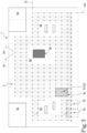
Figure 3 , this figure pertains to a scenario where there are two carriers, indicated as 3A and 3B, positioned above thebase element 2.Figure 3 represents the calculated graph G for the first carrier, 3A. The area around the second carrier, 3B, constitutes an excluded area EA. Advantageously, the excluded area EA indicative of presence of the carrier may be adapted based on the properties of the single carrier, e.g. presence of a gripper on the carrier or different dimensions thereof. - With reference to the starting point P1 of the
first carrier 3A, it is denoted as P1A. Thefirst carrier 3A needs to be moved to position P2, which is commonly referred to as the home position. - The control unit 4 (by means of the computer program executed therein which actuates the disclosed controlling method) is configured to calculate and generate points comprising graph G while maintaining a predetermined distance from the edges of the base element. In other words, there is an exclusion zone along the edges of the base element where points of graph G are not constructed, with a predetermined width.
-
Figure 4 represents the movement path P calculated by thecontrol unit 4 between the starting position P1 and the arrival position P2. It is worth noting that this movement path P is the shortest distance path between the starting position P1 and the arrival position P2. - On the other hand,
Figure 5 represents the graph G related tocarrier 3B. - According to another aspect, said movement path P is calculated by the
control unit 4 according to a mathematical function interpolating said portion of the potential movement points of the graph G. - In this manner, advantageously, it is possible to reconstruct a continuous-type movement path from a series of discrete points, as these points are connected by an interpolating mathematical function. At least a portion of the movement path P can be interpolated for one or more or all
carriers - For example, the interpolated portion may comprise the portion whereby the
carrier - Consequently, there is no deceleration/acceleration of each
carrier carrier - Preferably, the mathematical function is a spline function interpolating said portion of the potential movement points of the graph G.
- A spline is a mathematical curve that is defined by a set of control points (i.e. the portion of the potential movement points of the graph G defining the movement path P from the starting point P1 to the arrival point P2).
- According to another aspect, the
control unit 4 comprises aninterface unit 6, configured for receiving an event signal. - According to this aspect, the
control unit 4 is configured for detecting, or receiving information concerning, an event relative to the functioning of thecarriers base element 2 based on such event signal. - The term "detecting an event" refers to the fact that the
control unit 4, through issued commands, sensors, or signals, is instructed that a change in operating conditions has occurred. - The interface unit can comprise a wi-fi module or an electric connector having inputs or outputs or commands (buttons, touch screen, a receiver for vocal commands, etc.).
- The
control unit 4 could be the control unit of a packaging line, such as a PLC or defined by any computerized means (even remote) which can carry out the method according to the invention. - According to another aspect, the event signal could be the signal from the packaging line's control unit.
- Advantageously, the planar motor system 1 and the method according to the invention allows for a reduction in collisions between
carriers - Indeed, it should be noted that calculating the trajectory, specifically the movement path P, using a graph G allows for the reduction of any collision risks. This is achieved through precise calculations of the paths taken by the
different carriers - According to the present description, it is further disclosed an
apparatus 11 for handling products PR (in particular containers such as packages), comprising: - a planar motor system 1 as previously described,
- at least a container handling station 9, preferably a capping station, positioned at the
base element 2, wherein at least one carrier is configured to transit through the container handling station 9. - The
apparatus 11 further comprises: - a feeding conveyor 7, configured for conveying products PR in a predetermined entrance area of the
base element 2; - a
discharge conveyor 8 configured for receiving products PR in a predetermined exit area of thebase element 2 and conveying products PR outside thebase element 2. - The
apparatus 11 for handling products PR is part of a packaging line, which is not illustrated.
Claims (16)
- A method for controlling a planar motor system (1) comprising a base element (2) and a plurality of carriers (3A,3B,3C,3D), movable independently over the base element (2); the method comprising receiving an event signal indicative of an event related to the operation of the carriers (3A,3B,3C,3D) and/or of the base element (2), and performing the following steps, as a function of the event signal:- determining, for each carrier (3A,3B,3C,3D), a starting point (P1) and an arrival point (P2) as a function of the event signal,- generating a graph (G) defined by a plurality of potential movement points over the base element (2), including the starting point (P1) and the arrival point (P2),- calculating, for each carrier, a movement path (P) from the starting point (P1) to the arrival point (P2) comprising a portion of the potential movement points of the graph (G), and- driving the plurality of carriers (3A,3B,3C,3D) according to the calculated movement paths (P).
- The method according to claim 1, comprising driving the plurality of carriers (3A,3B,3C,3D) according to respective predetermined movement profiles and, if an event signal is received, updating the predetermined movement profiles based on the calculated movement paths (P), wherein the predetermined movement profiles are calculated based on an initial graph (G) defined by a plurality of potential movement points over the base element (2), including predetermined starting points and predetermined arrival points for each carrier (3A,3B,3C,3D) .
- The method according to any of the previous claims, comprising identifying a number of transit points (TP) indicative of a presence of respective handling stations, and calculating, for each carrier, the movement path (P) from the starting point (P1) to the arrival point (P2) also as a function of at least a transit point (TP).
- The method according to any of the previous claims, wherein the event signal is indicative of a variation in the number of carriers (3A,3B,3C,3D) operating over the base element (2) or a variation in the number of handling stations.
- The method according to any of the previous claims, comprising:- identifying a number of excluded areas (EA) on the base element (2) indicative of obstacles for at least one carrier in the plurality of carriers (3A,3B,3C,3D),- calculating the graph (G) excluding, from the plurality of potential movement points, points belonging to the excluded areas (EA) of the base element (2).
- The method according to the previous claim, wherein the excluded area (EA) comprises at least one of:- for each carrier (3A,3B,3C,3D), the regions over the base element (2) wherein the other carriers (3A,3B,3C,3D) are located,- obstacles present at the base element (2) hindering the movement of the carrier (3A, 3B, 3C, 3D) or the object carried by the carrier (3A, 3B, 3C, 3D),- an area proximate to the borders of the base element (2);- a safety area surrounding each carrier (3A, 3B, 3C, 3D), the safety area being calculated based on the dimensions of the single carrier.
- The method according to any previous claims, comprising generating the graph (G) and calculating the movement path (P) according to a Dijkstra algorithm.
- The method according to any previous claims, wherein the event signal is indicative of an error condition, and wherein the phase of determining, for each carrier (3A,3B,3C,3D), a starting point (P1) and an arrival point (P2) comprises identifying the starting point (P1) as an instant position of each carrier (3A, 3B, 3C, 3D) and the arrival point (P2) as a home position for each carrier (3A,3B,3C,3D).
- The method according to any of the previous claims, wherein:- the calculated movement path (P) from the starting point (P1) to the arrival point (P2) corresponds to the movement path, among the plurality of feasible moving points, which optimizes the sum of predetermined weight values associated to each connection between adjacent feasible moving points in the graph (G);- the predetermined weight values represent the distances between adjacent feasible moving points in the graph (G); and/or- the calculated path (P) from the starting point (P1) to the arrival point (P2) corresponding to the path which minimizes the overall distance from the starting point (P1) and the arrival point (P2).
- The method according to any of the previous claims, wherein the calculated path (P) from the starting point (P1) to the arrival point (P2) corresponds to the path, among the plurality of feasible moving points, which optimizes the sum of predetermined weight values associated to each connection between adjacent feasible moving points in the graph (G) and wherein the predetermined preferential weight values for some points of the potential movement points over the base element (2) are different for each carrier (3A,3B,3C,3D), the predetermined preferential weight values defining preferential different path for each carrier (3A,3B,3C,3D).
- The method according to any of the previous claims, comprising interpolating at least partly the portion of the potential movement points of the movement path, thereby reducing the number of movement points of the movement path.
- The method according to the previous claim, wherein the interpolated points comprise points whereby the carrier has a constant speed and/or a rectilinear path and/or whereby the carrier (3A,3B,3C,3D) carries an object.
- The method according to any of the previous claims 11 or 12, comprising interpolating at least partly said portion of the potential movement points by means of a spline function.
- A computer program product, loadable in a memory of at least one control unit, and comprising software code portions suitable for performing the phases of the method for controlling a planar motor system (1) according to any of the previous claims.
- A planar motor system (1), comprising:- a base element (2);- a plurality of carriers (3A,3B,3C,3D), movable independently over the base element (2);- a control unit (4) having stored thereon the computer program of the previous claim.
- Apparatus (11) for handling containers, comprising:- a planar motor system (1) according to the previous claim,- at least a container handling station (9), preferably a capping station, positioned at the base element (2), wherein at least one carrier (3A,3B,3C,3D) is configured to transit through the container handling station (9).
Applications Claiming Priority (1)
| Application Number | Priority Date | Filing Date | Title |
|---|---|---|---|
| IT102023000028095A IT202300028095A1 (en) | 2023-12-27 | 2023-12-27 | A METHOD FOR CONTROLLING A PLANAR MOTOR SYSTEM, A COMPUTER PRODUCT FOR IMPLEMENTING THE METHOD, A PLANAR MOTOR SYSTEM, AND A MANIPULATION APPARATUS COMPRISING THE PLANAR MOTOR SYSTEM |
Publications (1)
| Publication Number | Publication Date |
|---|---|
| EP4579364A1 true EP4579364A1 (en) | 2025-07-02 |
Family
ID=90057504
Family Applications (1)
| Application Number | Title | Priority Date | Filing Date |
|---|---|---|---|
| EP24219883.6A Pending EP4579364A1 (en) | 2023-12-27 | 2024-12-13 | A method for controlling a planar motor system, a computer program product for actuating the method, a planar motor system and an handling apparatus comprising the planar motor system |
Country Status (3)
| Country | Link |
|---|---|
| EP (1) | EP4579364A1 (en) |
| IT (1) | IT202300028095A1 (en) |
| WO (1) | WO2025140872A1 (en) |
Citations (2)
| Publication number | Priority date | Publication date | Assignee | Title |
|---|---|---|---|---|
| US20180180428A1 (en) * | 2016-12-22 | 2018-06-28 | Gestalt Systems GmbH | Navigation for vehicles |
| WO2021228733A1 (en) * | 2020-05-11 | 2021-11-18 | Roche Diagnostics Gmbh | Distribution system |
-
2023
- 2023-12-27 IT IT102023000028095A patent/IT202300028095A1/en unknown
-
2024
- 2024-12-13 EP EP24219883.6A patent/EP4579364A1/en active Pending
- 2024-12-13 WO PCT/EP2024/086306 patent/WO2025140872A1/en active Pending
Patent Citations (2)
| Publication number | Priority date | Publication date | Assignee | Title |
|---|---|---|---|---|
| US20180180428A1 (en) * | 2016-12-22 | 2018-06-28 | Gestalt Systems GmbH | Navigation for vehicles |
| WO2021228733A1 (en) * | 2020-05-11 | 2021-11-18 | Roche Diagnostics Gmbh | Distribution system |
Also Published As
| Publication number | Publication date |
|---|---|
| IT202300028095A1 (en) | 2025-06-27 |
| WO2025140872A1 (en) | 2025-07-03 |
Similar Documents
| Publication | Publication Date | Title |
|---|---|---|
| EP1635995B1 (en) | Control method for machines, including a system, computer program, data signal and gui | |
| EP3501880B1 (en) | Linear drive system having central, distributed and group control | |
| US11829144B2 (en) | Mover system | |
| CA2882452C (en) | Method of material handling with automatic guided vehicles | |
| CA2894546C (en) | Method of material handling with automatic guided vehicles | |
| CN109789545B (en) | Method and system for controlling speed of a transport path | |
| EP3291039B1 (en) | Article transport facility | |
| US11912508B2 (en) | Method for controlling a transport unit of a transport device in the form of a long-stator linear motor | |
| US20150114796A1 (en) | Conveyor Device for the Conveyance of Workpieces, Specifically of Circuit Boards, in the Conveyance Direction Along a Conveyance Path | |
| CN115993815A (en) | Motion control method and computer program product for mobile robot | |
| JP2022074478A (en) | Goods transport equipment | |
| WO2025140872A1 (en) | A method for controlling a planar motor system, a computer program product for actuating the method, a planar motor system and an handling apparatus comprising the planar motor system | |
| JP4442611B2 (en) | Traveling vehicle system | |
| CN114981187A (en) | Article storage facility | |
| US11339003B2 (en) | Transfer apparatus and transfer method | |
| EP3620879B1 (en) | A system and method for controlling a packaging machine | |
| JP4432974B2 (en) | Traveling vehicle system | |
| JP7856049B2 (en) | Goods handling equipment | |
| JP2019182638A (en) | Article conveyance facility | |
| JP2019120992A (en) | AGV control system | |
| US20120070260A1 (en) | Conveying system having endless drive medium and method for delivering/receiving article therein | |
| CN109911557B (en) | Transport system, method for controlling a transport system and transport system assembly | |
| CN118876058B (en) | Collision detection method, device, equipment and system | |
| JP7805798B2 (en) | Delivery system and delivery method | |
| JP4941622B2 (en) | Transfer line transfer control device |
Legal Events
| Date | Code | Title | Description |
|---|---|---|---|
| PUAI | Public reference made under article 153(3) epc to a published international application that has entered the european phase |
Free format text: ORIGINAL CODE: 0009012 |
|
| STAA | Information on the status of an ep patent application or granted ep patent |
Free format text: STATUS: THE APPLICATION HAS BEEN PUBLISHED |
|
| AK | Designated contracting states |
Kind code of ref document: A1 Designated state(s): AL AT BE BG CH CY CZ DE DK EE ES FI FR GB GR HR HU IE IS IT LI LT LU LV MC ME MK MT NL NO PL PT RO RS SE SI SK SM TR |
|
| STAA | Information on the status of an ep patent application or granted ep patent |
Free format text: STATUS: REQUEST FOR EXAMINATION WAS MADE |
|
| 17P | Request for examination filed |
Effective date: 20260102 |