EP4579338A1 - Vehicle imaging device with large aspect ratio using projection optical system - Google Patents
Vehicle imaging device with large aspect ratio using projection optical system Download PDFInfo
- Publication number
- EP4579338A1 EP4579338A1 EP23872668.1A EP23872668A EP4579338A1 EP 4579338 A1 EP4579338 A1 EP 4579338A1 EP 23872668 A EP23872668 A EP 23872668A EP 4579338 A1 EP4579338 A1 EP 4579338A1
- Authority
- EP
- European Patent Office
- Prior art keywords
- region
- mirror
- prism
- pbs
- pgu
- Prior art date
- Legal status (The legal status is an assumption and is not a legal conclusion. Google has not performed a legal analysis and makes no representation as to the accuracy of the status listed.)
- Pending
Links
Images















Classifications
-
- B—PERFORMING OPERATIONS; TRANSPORTING
- B60—VEHICLES IN GENERAL
- B60K—ARRANGEMENT OR MOUNTING OF PROPULSION UNITS OR OF TRANSMISSIONS IN VEHICLES; ARRANGEMENT OR MOUNTING OF PLURAL DIVERSE PRIME-MOVERS IN VEHICLES; AUXILIARY DRIVES FOR VEHICLES; INSTRUMENTATION OR DASHBOARDS FOR VEHICLES; ARRANGEMENTS IN CONNECTION WITH COOLING, AIR INTAKE, GAS EXHAUST OR FUEL SUPPLY OF PROPULSION UNITS IN VEHICLES
- B60K35/00—Instruments specially adapted for vehicles; Arrangement of instruments in or on vehicles
-
- B—PERFORMING OPERATIONS; TRANSPORTING
- B60—VEHICLES IN GENERAL
- B60K—ARRANGEMENT OR MOUNTING OF PROPULSION UNITS OR OF TRANSMISSIONS IN VEHICLES; ARRANGEMENT OR MOUNTING OF PLURAL DIVERSE PRIME-MOVERS IN VEHICLES; AUXILIARY DRIVES FOR VEHICLES; INSTRUMENTATION OR DASHBOARDS FOR VEHICLES; ARRANGEMENTS IN CONNECTION WITH COOLING, AIR INTAKE, GAS EXHAUST OR FUEL SUPPLY OF PROPULSION UNITS IN VEHICLES
- B60K35/00—Instruments specially adapted for vehicles; Arrangement of instruments in or on vehicles
- B60K35/20—Output arrangements, i.e. from vehicle to user, associated with vehicle functions or specially adapted therefor
- B60K35/21—Output arrangements, i.e. from vehicle to user, associated with vehicle functions or specially adapted therefor using visual output, e.g. blinking lights or matrix displays
- B60K35/22—Display screens
-
- B—PERFORMING OPERATIONS; TRANSPORTING
- B60—VEHICLES IN GENERAL
- B60K—ARRANGEMENT OR MOUNTING OF PROPULSION UNITS OR OF TRANSMISSIONS IN VEHICLES; ARRANGEMENT OR MOUNTING OF PLURAL DIVERSE PRIME-MOVERS IN VEHICLES; AUXILIARY DRIVES FOR VEHICLES; INSTRUMENTATION OR DASHBOARDS FOR VEHICLES; ARRANGEMENTS IN CONNECTION WITH COOLING, AIR INTAKE, GAS EXHAUST OR FUEL SUPPLY OF PROPULSION UNITS IN VEHICLES
- B60K35/00—Instruments specially adapted for vehicles; Arrangement of instruments in or on vehicles
- B60K35/20—Output arrangements, i.e. from vehicle to user, associated with vehicle functions or specially adapted therefor
- B60K35/21—Output arrangements, i.e. from vehicle to user, associated with vehicle functions or specially adapted therefor using visual output, e.g. blinking lights or matrix displays
- B60K35/23—Head-up displays [HUD]
-
- B—PERFORMING OPERATIONS; TRANSPORTING
- B60—VEHICLES IN GENERAL
- B60K—ARRANGEMENT OR MOUNTING OF PROPULSION UNITS OR OF TRANSMISSIONS IN VEHICLES; ARRANGEMENT OR MOUNTING OF PLURAL DIVERSE PRIME-MOVERS IN VEHICLES; AUXILIARY DRIVES FOR VEHICLES; INSTRUMENTATION OR DASHBOARDS FOR VEHICLES; ARRANGEMENTS IN CONNECTION WITH COOLING, AIR INTAKE, GAS EXHAUST OR FUEL SUPPLY OF PROPULSION UNITS IN VEHICLES
- B60K35/00—Instruments specially adapted for vehicles; Arrangement of instruments in or on vehicles
- B60K35/20—Output arrangements, i.e. from vehicle to user, associated with vehicle functions or specially adapted therefor
- B60K35/21—Output arrangements, i.e. from vehicle to user, associated with vehicle functions or specially adapted therefor using visual output, e.g. blinking lights or matrix displays
- B60K35/23—Head-up displays [HUD]
- B60K35/231—Head-up displays [HUD] characterised by their arrangement or structure for integration into vehicles
-
- B—PERFORMING OPERATIONS; TRANSPORTING
- B60—VEHICLES IN GENERAL
- B60K—ARRANGEMENT OR MOUNTING OF PROPULSION UNITS OR OF TRANSMISSIONS IN VEHICLES; ARRANGEMENT OR MOUNTING OF PLURAL DIVERSE PRIME-MOVERS IN VEHICLES; AUXILIARY DRIVES FOR VEHICLES; INSTRUMENTATION OR DASHBOARDS FOR VEHICLES; ARRANGEMENTS IN CONNECTION WITH COOLING, AIR INTAKE, GAS EXHAUST OR FUEL SUPPLY OF PROPULSION UNITS IN VEHICLES
- B60K35/00—Instruments specially adapted for vehicles; Arrangement of instruments in or on vehicles
- B60K35/20—Output arrangements, i.e. from vehicle to user, associated with vehicle functions or specially adapted therefor
- B60K35/28—Output arrangements, i.e. from vehicle to user, associated with vehicle functions or specially adapted therefor characterised by the type of the output information, e.g. video entertainment or vehicle dynamics information; characterised by the purpose of the output information, e.g. for attracting the attention of the driver
-
- B—PERFORMING OPERATIONS; TRANSPORTING
- B60—VEHICLES IN GENERAL
- B60K—ARRANGEMENT OR MOUNTING OF PROPULSION UNITS OR OF TRANSMISSIONS IN VEHICLES; ARRANGEMENT OR MOUNTING OF PLURAL DIVERSE PRIME-MOVERS IN VEHICLES; AUXILIARY DRIVES FOR VEHICLES; INSTRUMENTATION OR DASHBOARDS FOR VEHICLES; ARRANGEMENTS IN CONNECTION WITH COOLING, AIR INTAKE, GAS EXHAUST OR FUEL SUPPLY OF PROPULSION UNITS IN VEHICLES
- B60K35/00—Instruments specially adapted for vehicles; Arrangement of instruments in or on vehicles
- B60K35/60—Instruments characterised by their location or relative disposition in or on vehicles
-
- B—PERFORMING OPERATIONS; TRANSPORTING
- B60—VEHICLES IN GENERAL
- B60K—ARRANGEMENT OR MOUNTING OF PROPULSION UNITS OR OF TRANSMISSIONS IN VEHICLES; ARRANGEMENT OR MOUNTING OF PLURAL DIVERSE PRIME-MOVERS IN VEHICLES; AUXILIARY DRIVES FOR VEHICLES; INSTRUMENTATION OR DASHBOARDS FOR VEHICLES; ARRANGEMENTS IN CONNECTION WITH COOLING, AIR INTAKE, GAS EXHAUST OR FUEL SUPPLY OF PROPULSION UNITS IN VEHICLES
- B60K35/00—Instruments specially adapted for vehicles; Arrangement of instruments in or on vehicles
- B60K35/80—Arrangements for controlling instruments
- B60K35/81—Arrangements for controlling instruments for controlling displays
-
- B—PERFORMING OPERATIONS; TRANSPORTING
- B60—VEHICLES IN GENERAL
- B60K—ARRANGEMENT OR MOUNTING OF PROPULSION UNITS OR OF TRANSMISSIONS IN VEHICLES; ARRANGEMENT OR MOUNTING OF PLURAL DIVERSE PRIME-MOVERS IN VEHICLES; AUXILIARY DRIVES FOR VEHICLES; INSTRUMENTATION OR DASHBOARDS FOR VEHICLES; ARRANGEMENTS IN CONNECTION WITH COOLING, AIR INTAKE, GAS EXHAUST OR FUEL SUPPLY OF PROPULSION UNITS IN VEHICLES
- B60K37/00—Dashboards
- B60K37/20—Dashboard panels
-
- G—PHYSICS
- G02—OPTICS
- G02B—OPTICAL ELEMENTS, SYSTEMS OR APPARATUS
- G02B27/00—Optical systems or apparatus not provided for by any of the groups G02B1/00 - G02B26/00, G02B30/00
- G02B27/01—Head-up displays
-
- G—PHYSICS
- G02—OPTICS
- G02B—OPTICAL ELEMENTS, SYSTEMS OR APPARATUS
- G02B27/00—Optical systems or apparatus not provided for by any of the groups G02B1/00 - G02B26/00, G02B30/00
- G02B27/01—Head-up displays
- G02B27/0101—Head-up displays characterised by optical features
-
- G—PHYSICS
- G02—OPTICS
- G02B—OPTICAL ELEMENTS, SYSTEMS OR APPARATUS
- G02B27/00—Optical systems or apparatus not provided for by any of the groups G02B1/00 - G02B26/00, G02B30/00
- G02B27/01—Head-up displays
- G02B27/0149—Head-up displays characterised by mechanical features
-
- G—PHYSICS
- G02—OPTICS
- G02B—OPTICAL ELEMENTS, SYSTEMS OR APPARATUS
- G02B27/00—Optical systems or apparatus not provided for by any of the groups G02B1/00 - G02B26/00, G02B30/00
- G02B27/01—Head-up displays
- G02B27/0179—Display position adjusting means not related to the information to be displayed
-
- G—PHYSICS
- G02—OPTICS
- G02B—OPTICAL ELEMENTS, SYSTEMS OR APPARATUS
- G02B3/00—Simple or compound lenses
- G02B3/0006—Arrays
- G02B3/0012—Arrays characterised by the manufacturing method
-
- G—PHYSICS
- G03—PHOTOGRAPHY; CINEMATOGRAPHY; ANALOGOUS TECHNIQUES USING WAVES OTHER THAN OPTICAL WAVES; ELECTROGRAPHY; HOLOGRAPHY
- G03B—APPARATUS OR ARRANGEMENTS FOR TAKING PHOTOGRAPHS OR FOR PROJECTING OR VIEWING THEM; APPARATUS OR ARRANGEMENTS EMPLOYING ANALOGOUS TECHNIQUES USING WAVES OTHER THAN OPTICAL WAVES; ACCESSORIES THEREFOR
- G03B21/00—Projectors or projection-type viewers; Accessories therefor
-
- G—PHYSICS
- G03—PHOTOGRAPHY; CINEMATOGRAPHY; ANALOGOUS TECHNIQUES USING WAVES OTHER THAN OPTICAL WAVES; ELECTROGRAPHY; HOLOGRAPHY
- G03B—APPARATUS OR ARRANGEMENTS FOR TAKING PHOTOGRAPHS OR FOR PROJECTING OR VIEWING THEM; APPARATUS OR ARRANGEMENTS EMPLOYING ANALOGOUS TECHNIQUES USING WAVES OTHER THAN OPTICAL WAVES; ACCESSORIES THEREFOR
- G03B21/00—Projectors or projection-type viewers; Accessories therefor
- G03B21/005—Projectors using an electronic spatial light modulator but not peculiar thereto
- G03B21/008—Projectors using an electronic spatial light modulator but not peculiar thereto using micromirror devices
-
- G—PHYSICS
- G03—PHOTOGRAPHY; CINEMATOGRAPHY; ANALOGOUS TECHNIQUES USING WAVES OTHER THAN OPTICAL WAVES; ELECTROGRAPHY; HOLOGRAPHY
- G03B—APPARATUS OR ARRANGEMENTS FOR TAKING PHOTOGRAPHS OR FOR PROJECTING OR VIEWING THEM; APPARATUS OR ARRANGEMENTS EMPLOYING ANALOGOUS TECHNIQUES USING WAVES OTHER THAN OPTICAL WAVES; ACCESSORIES THEREFOR
- G03B21/00—Projectors or projection-type viewers; Accessories therefor
- G03B21/54—Accessories
- G03B21/56—Projection screens
- G03B21/60—Projection screens characterised by the nature of the surface
- G03B21/62—Translucent screens
- G03B21/625—Lenticular translucent screens
-
- B—PERFORMING OPERATIONS; TRANSPORTING
- B60—VEHICLES IN GENERAL
- B60K—ARRANGEMENT OR MOUNTING OF PROPULSION UNITS OR OF TRANSMISSIONS IN VEHICLES; ARRANGEMENT OR MOUNTING OF PLURAL DIVERSE PRIME-MOVERS IN VEHICLES; AUXILIARY DRIVES FOR VEHICLES; INSTRUMENTATION OR DASHBOARDS FOR VEHICLES; ARRANGEMENTS IN CONNECTION WITH COOLING, AIR INTAKE, GAS EXHAUST OR FUEL SUPPLY OF PROPULSION UNITS IN VEHICLES
- B60K2360/00—Indexing scheme associated with groups B60K35/00 or B60K37/00 relating to details of instruments or dashboards
- B60K2360/16—Type of output information
- B60K2360/166—Navigation
-
- B—PERFORMING OPERATIONS; TRANSPORTING
- B60—VEHICLES IN GENERAL
- B60K—ARRANGEMENT OR MOUNTING OF PROPULSION UNITS OR OF TRANSMISSIONS IN VEHICLES; ARRANGEMENT OR MOUNTING OF PLURAL DIVERSE PRIME-MOVERS IN VEHICLES; AUXILIARY DRIVES FOR VEHICLES; INSTRUMENTATION OR DASHBOARDS FOR VEHICLES; ARRANGEMENTS IN CONNECTION WITH COOLING, AIR INTAKE, GAS EXHAUST OR FUEL SUPPLY OF PROPULSION UNITS IN VEHICLES
- B60K2360/00—Indexing scheme associated with groups B60K35/00 or B60K37/00 relating to details of instruments or dashboards
- B60K2360/16—Type of output information
- B60K2360/167—Vehicle dynamics information
-
- B—PERFORMING OPERATIONS; TRANSPORTING
- B60—VEHICLES IN GENERAL
- B60K—ARRANGEMENT OR MOUNTING OF PROPULSION UNITS OR OF TRANSMISSIONS IN VEHICLES; ARRANGEMENT OR MOUNTING OF PLURAL DIVERSE PRIME-MOVERS IN VEHICLES; AUXILIARY DRIVES FOR VEHICLES; INSTRUMENTATION OR DASHBOARDS FOR VEHICLES; ARRANGEMENTS IN CONNECTION WITH COOLING, AIR INTAKE, GAS EXHAUST OR FUEL SUPPLY OF PROPULSION UNITS IN VEHICLES
- B60K2360/00—Indexing scheme associated with groups B60K35/00 or B60K37/00 relating to details of instruments or dashboards
- B60K2360/20—Optical features of instruments
- B60K2360/23—Optical features of instruments using reflectors
-
- G—PHYSICS
- G02—OPTICS
- G02B—OPTICAL ELEMENTS, SYSTEMS OR APPARATUS
- G02B27/00—Optical systems or apparatus not provided for by any of the groups G02B1/00 - G02B26/00, G02B30/00
- G02B27/01—Head-up displays
- G02B27/0101—Head-up displays characterised by optical features
- G02B2027/0118—Head-up displays characterised by optical features comprising devices for improving the contrast of the display / brillance control visibility
-
- G—PHYSICS
- G02—OPTICS
- G02B—OPTICAL ELEMENTS, SYSTEMS OR APPARATUS
- G02B27/00—Optical systems or apparatus not provided for by any of the groups G02B1/00 - G02B26/00, G02B30/00
- G02B27/01—Head-up displays
- G02B27/0101—Head-up displays characterised by optical features
- G02B2027/013—Head-up displays characterised by optical features comprising a combiner of particular shape, e.g. curvature
-
- G—PHYSICS
- G02—OPTICS
- G02B—OPTICAL ELEMENTS, SYSTEMS OR APPARATUS
- G02B27/00—Optical systems or apparatus not provided for by any of the groups G02B1/00 - G02B26/00, G02B30/00
- G02B27/01—Head-up displays
- G02B27/0149—Head-up displays characterised by mechanical features
- G02B2027/0154—Head-up displays characterised by mechanical features with movable elements
-
- G—PHYSICS
- G02—OPTICS
- G02B—OPTICAL ELEMENTS, SYSTEMS OR APPARATUS
- G02B27/00—Optical systems or apparatus not provided for by any of the groups G02B1/00 - G02B26/00, G02B30/00
- G02B27/28—Optical systems or apparatus not provided for by any of the groups G02B1/00 - G02B26/00, G02B30/00 for polarising
- G02B27/283—Optical systems or apparatus not provided for by any of the groups G02B1/00 - G02B26/00, G02B30/00 for polarising used for beam splitting or combining
-
- G—PHYSICS
- G02—OPTICS
- G02B—OPTICAL ELEMENTS, SYSTEMS OR APPARATUS
- G02B3/00—Simple or compound lenses
- G02B3/02—Simple or compound lenses with non-spherical faces
- G02B3/08—Simple or compound lenses with non-spherical faces with discontinuous faces, e.g. Fresnel lens
Definitions
- This specification relates to a vehicle imaging device.
- One particular implementation relates to a vehicle imaging device having a large aspect ratio using a projection optical system.
- a vehicle is an apparatus capable of being moved in a desired direction by a user who is on board.
- a representative example of a vehicle may be an automobile.
- ADAS advanced driver assistance system
- an autonomous vehicle is actively under development.
- a vehicle display that shows various driving information of the vehicle is located below a driver's forward visual field for driving, which affects driving safety, a phenomenon known as rubbernecking. Therefore, a vehicle imaging device, such as a head-up display (HUD), may be mounted on a vehicle to enhance driving safety by projecting an image on a windshield at the front of the vehicle, positioned close to the driver's line of sight while driving.
- HUD head-up display
- the prism may include a first absorbing layer attached to upper and side surfaces of the prism corresponding to the first region, and a second absorbing layer attached to upper and side surfaces of the prism corresponding to the second region.
- a P-wave of an optical signal output to the first region may pass through the first PBS arranged in the first region to be absorbed by the first absorbing layer.
- An S-wave of the optical signal output to the first region may be reflected from the first PBS and the second PBS to be incident onto the projection lens.
- the PGU may further include glass tiltably arranged between the polarization conversion plate and the prism in the first region of the display panel.
- the processor may control a tilt angle of the glass so that first pixels of the first data set and second pixels of the second data set are sequentially arranged.
- more information can be provided through an image having a large aspect ratio at a position, which is close to a driver's visual field for driving, in an imaging device having a large aspect ratio for the driver.
- an imaging device implemented by connecting a plurality of image modules can overcome the limitation of natural image implementation due to the lack of continuity at a connection portion of an image.
- a continuous image associated with driving-related information can be implemented using a single image module in a specific region of a windshield in front of a vehicle.
- a vehicle imaging device having a small and thin volume can be provided by using a projection optical system structure having a reflective structure and a screen panel offset to one side or another side.
- a vehicle imaging device with a thin and small volume can be implemented using an ultra short throw (UST) projector and a special screen in a limited space inside a vehicle where a steering wheel, pedals, or CQT are placed.
- UST ultra short throw
- a vehicle according to an embodiment of the disclosure may be understood as a conception including automobiles, motorcycles, and the like. Hereinafter, the vehicle will be described based on a car.
- a left side of a vehicle refers to a left side in a driving direction of the vehicle
- a right side of the vehicle refers to a right side in the driving direction
- FIG. 1 is a view illustrating appearance of a vehicle according to an embodiment.
- FIG. 2 is a diagram illustrating the appearance of the vehicle at various angles.
- FIGS. 3 and 4 are diagrams illustrating an inside of a vehicle according to an embodiment.
- FIG. 5 is a block diagram illustrating a vehicle according to an embodiment.
- a vehicle 100 may include wheels rotating by a power source, and a steering input apparatus 510 for adjusting a driving (ongoing, moving) direction of the vehicle 100.
- the vehicle 100 may be an autonomous vehicle.
- the vehicle 100 may be converted from the manual mode into the autonomous mode or from the autonomous mode into the manual mode based on a user input received through a user interface device 200.
- the vehicle 100 may be switched into the autonomous mode or the manual mode based on traveling situation information.
- the traveling situation information may be generated based on object information provided from an object detection device 300.
- the vehicle 100 may be switched from the manual mode into the autonomous mode or from the autonomous module into the manual mode based on traveling situation information generated in the object detection device 300.
- the vehicle 100 may be switched from the manual mode into the autonomous mode or from the autonomous mode into the manual mode based on traveling situation information received through a communication device 400.
- the vehicle 100 may be switched from the manual mode into the autonomous mode or from the autonomous module into the manual mode based on information, data or signal provided from an external device.
- the vehicle 100 When the vehicle 100 is driven in the autonomous mode, the vehicle 100 may be driven based on a driving system 700.
- the autonomous vehicle 100 may be driven based on information, data, or signals that are generated by a traveling system 710, a parking-lot departure system 740, and a parking system 750.
- the autonomous vehicle 100 may receive a user input for driving through a driving operation device 500.
- the vehicle 100 may be driven based on the user input received through the driving operation device 500.
- an overall length refers to a length from a front end to a rear end of the vehicle 100
- a width refers to a width of the vehicle 100
- a height refers to a length from a bottom of a wheel to a roof.
- an overall-length direction L may refer to a direction which is a criterion for measuring the overall length of the vehicle 100
- a width direction W may refer to a direction that is a criterion for measuring a width of the vehicle 100
- a height direction H may refer to a direction that is a criterion for measuring a height of the vehicle 100
- the vehicle 100 may include a user interface device 200, an object detection device 300, a communication device 400, a driving operation device 500, a vehicle drive device 600, a driving system 700, a navigation system 770, a sensing unit 120, an interface unit 130, a memory 140, a controller 170, and a power supply unit 190.
- the vehicle 100 may include more components in addition to components to be explained in this specification or may not include some of those components to be explained in this specification.
- the user interface device 200 is a device for communication between the vehicle 100 and a user.
- the user interface device 200 may receive a user input and provide information generated in the vehicle 100 to the user.
- the vehicle 100 may implement user interfaces (Uls) or user experiences (UXs) through the user interface device 200.
- Users user interfaces
- UXs user experiences
- the user interface device 200 may include an input unit 210, an internal camera 220, a biometric detection unit 230, an output unit 250, and a processor 270.
- the user interface device 200 may include more components in addition to components to be explained in this specification or may not include some of those components to be explained in this specification.
- the input unit 200 may allow the user to input information. Data collected in the input unit 120 may be analyzed by the processor 270 and processed as a user's control command.
- the input unit 200 may be disposed inside the vehicle.
- the input unit 200 may be disposed on one region of a steering wheel, one region of an instrument panel, one region of a seat, one region of each pillar, one region of a door, one region of a center console, one region of a headlining, one region of a sun visor, one region of a windshield, one region of a window, or the like.
- the input unit 200 may include a voice input part 211, a gesture input part 212, a touch input part 213, and a mechanical input part 214.
- the audio input part 211 may convert a user's voice input into an electric signal.
- the converted electric signal may be provided to the processor 270 or the controller 170.
- the audio input part 211 may include at least one microphone.
- the gesture input part 212 may convert a user's gesture input into an electric signal.
- the converted electric signal may be provided to the processor 270 or the controller 170.
- the gesture input part 212 may include at least one of an infrared sensor and an image sensor for detecting the user's gesture input.
- the gesture input part 212 may detect a user's three-dimensional (3D) gesture input.
- the gesture input part 212 may include a light-emitting diode outputting a plurality of infrared rays or a plurality of image sensors.
- the gesture input part 212 may detect the user's 3D gesture input by a time of flight (TOF) method, a structured light method or a disparity method.
- TOF time of flight
- the touch input part 213 may convert the user's touch input into an electric signal.
- the converted electric signal may be provided to the processor 270 or the controller 170
- the touch input part 213 may include a touch sensor for detecting the user's touch input.
- the touch input part 213 may be integrated with the display 251 so as to implement a touch screen.
- the touch screen may provide an input interface and an output interface between the vehicle 100 and the user.
- the mechanical input part 214 may include at least one of a button, a dome switch, a jog wheel, and a jog switch. An electric signal generated by the mechanical input part 214 may be provided to the processor 270 or the controller 170.
- the mechanical input part 214 may be arranged on a steering wheel, a center fascia, a center console, a cockpit module, a door, and the like.
- the internal camera 220 may acquire an internal image of the vehicle.
- the processor 270 may detect a user's state based on the internal image of the vehicle.
- the processor 270 may acquire information related to the user's gaze from the internal image of the vehicle.
- the processor 270 may detect a user gesture from the internal image of the vehicle.
- the biometric detection unit 230 may acquire the user's biometric information.
- the biometric detection unit 230 may include a sensor for detecting the user's biometric information and acquire fingerprint information and heart rate information regarding the user using the sensor.
- the biometric information may be used for user authentication.
- the display 251 may output graphic objects corresponding to various types of information.
- the display 251 may include at least one of a liquid crystal display (LCD), a thin film transistor-LCD (TFT LCD), an organic light-emitting diode (OLED), a flexible display, a three-dimensional (3D) display and an e-ink display.
- LCD liquid crystal display
- TFT LCD thin film transistor-LCD
- OLED organic light-emitting diode
- flexible display a three-dimensional (3D) display
- 3D three-dimensional
- the display 251 may be inter-layered or integrated with a touch input part 213 to implement a touch screen.
- the display 251 may include a transparent display.
- the transparent display may be attached to the windshield or the window.
- the user interface device 200 may include a plurality of displays 251a to 251g.
- the display 251 may be arranged in one region of the steering wheel, one region 521a, 251b, 251e of the instrument panel, one region 251d of the seat, one region 251f of each pillar, one region 251g of the door, one region of the center console, one region of the headlining, or one region of the sun visor, or implemented in one region 251c of the windshield or one region 251h of the window.
- the audio output part 252 may convert an electric signal provided by the processor 270 or the controller 170 into an audio signal and output the audio signal. To this end, the audio output part 252 may include at least one speaker.
- an aspect of this specification is to provide a vehicle imaging device having a large aspect ratio using a projection optical system related to the vehicle. Another aspect of this specification is to display driving-related information on a screen having a large aspect ratio in a specific region of the windshield at the front of the vehicle. Still another aspect of this specification is to provide a vehicle imaging device having an optical structure and a special screen for allowing an image to have a large aspect ratio by using a single image module. Still another aspect of this specification is to implement continuous images related to driving-related information to have a large aspect ratio by using a single image module. Still another aspect of this specification is to provide a small and thin vehicle imaging device.
- FIG. 6A is a view of a configuration in which a screen of a certain ratio is formed in a specific region of front glass of a vehicle.
- FIG. 6B is a view of a structure in which a vehicle imaging device for creating the screen of the certain ratio of FIG. 6A is arranged inside a dashboard of the vehicle.
- an image having a width Wa in one axial direction and a length La in another axial direction may be displayed in a specific region 251R of a windshield of a vehicle.
- the image may be configured to include a plurality of image regions displaying information necessary for driving the vehicle.
- the plurality of image regions may include a first image region IR1 to a third image region IR3.
- a first image including vehicle-related information may be displayed in the first image region IR1 closest to a driver's visual field range in the vehicle.
- a second image associated with a vehicle driving path may be displayed in the second image region IR2.
- a third image associated with a map including an origin and a destination may be displayed in the third image region IR3.
- the width Wa in the one axial direction may be set to be longer than the length La in the another axial direction by a certain ratio, for example, at least 5 times.
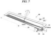
- the vehicle imaging device 1000 may be configured to include a cover 1010, a picture generation unit 1100, a screen panel 1200a, 1200, and a mirror 1300.
- the mirror 1300 may be implemented as a second mirror 1320a, 1320 having a curved shape.
- the mirror 1300 may alternatively be configured to include only one of a first mirror 1310a and a second mirror 1320a.
- the mirror 1300 may alternatively be configured to include only one of a first mirror 1310 and a second mirror 1320.
- the mirror 1300 may be configured to include a first mirror 1310a, 1310 and a second mirror 1320a, 1320.
- the cover 1010 may form the appearance of the dashboard of the vehicle.
- the picture generation unit 1100, the screen panel 1200a, 1200, the first mirror 1310a, 1310, and the second mirror 1320a, 1320 may be arranged inside the cover 1010.
- the first mirror 1310a, 1310 may be arranged on one side or another side of the picture generation unit 1100.
- the first mirror 1310a, 1310 may be configured to change a light path by reflecting light emitted to the one side or another side of the picture generation unit 1100.
- the second mirror 1320a, 1320 may be arranged between the first mirror 1310a, 1310 and the screen panel 1200a, 1200.
- the second mirror 1320a, 1320 may be configured to reflect light reflected from the first mirror 1310a, 1310 and transmit the reflected light to the screen panel 1200a, 1200.
- An image by light reflected from the screen panel 1200a, 1200 may be displayed in the specific region 251R of the windshield of the vehicle in a manner that a width Wa of the image in one axial direction is greater than a length La in another axial direction.
- the specific region 251R of the windshield may be a region within the driver's visual field range in the vehicle.
- the picture generation unit 1100 and the mirror 1320a may be arranged on a left side which is one side of the screen panel 1200a.
- the picture generation unit 1100, the first mirror 1310a, and the second mirror 1320a may be arranged on the left side which is the one side of the screen panel 1200a.
- the screen panel 1200a may be formed with a tilted structure in which a vertical distance to the cover 1010 decreases from left to right.
- the screen panel 1200a may be formed to have a positive slope from left to right.
- Light emitted from the picture generation unit 1100 may be reflected by the first mirror 1310a, the second mirror 1320a, and the screen panel 1200a, and may disperse within a certain angular range based on a direction perpendicular to the cover 1010.
- the picture generation unit 1100 and the mirror 1320 may be arranged on the right side which is another side of the screen panel 1200.
- the picture generation unit 1100, the first mirror 1310, and the second mirror 1320 may be arranged on the right side which is the another side of the screen panel 1200.
- the screen panel 1200 may be formed to have a negative slope from left to right.
- the screen panel 1200 may be formed with a tilted structure in which a vertical distance to the cover 1010 increases from left to right. Light emitted from the picture generation unit 1100 may be reflected by the first mirror 1310, the second mirror 1320, and the screen panel 1200, and may diffuse within a certain angular range based on the direction perpendicular to the cover 1010.
- the screen panel 1200a, 1200 may be formed inside the dashboard to have a first width W1 in one axial direction and a first length L1 in another axial direction.
- a ratio of the first width W1 in the one axial direction and the first length L1 in the another axial direction may be set as a first ratio.
- a ratio of the width Wa and the length La of an image displayed on a windshield may be set as a second ratio.
- a top of the image displayed on the windshield may be positioned lower than a center line of the windshield.
- the first and second ratios may be set to be at least 5:1.
- the screen panel may include a plurality of layers.
- FIG. 9A is a view of a structure in which a screen panel of a vehicle imaging device according to this specification includes a plurality of layers.
- a reflective layer 1210 of the screen panel 1200 may have patterns 1212 arranged with being spaced apart from each other.
- the patterns 1212 of the reflective layer 1210 may constitute a partial area of an ellipse formed in one and another axial directions.
- the patterns 1212 of the reflective layer 1210 may be arranged spaced apart in the another axial direction.
- the screen panel 1200 may be configured to include a reflective layer 1210 and a diffusion layer 1220.
- the reflective layer 1210 may have a fresnel structure and may also be referred to as a fresnel layer.
- the reflective layer 1210 may be arranged so that the patterns formed in the another axial direction are spaced apart in the one axial direction.
- the diffusion layer 1220 may be arranged on one surface of the reflective layer 1210. A rear surface of the diffusion layer 1220 may be attached to the one surface of the reflective layer 1210.
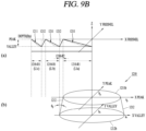
- FIG. 9B is a view of a fresnel structure of a reflective layer of a screen panel according to this specification.
- (a) of FIG. 9B is a cross-sectional view of the reflective layer 1210 of the screen panel.
- the reflective layer 1210 of the screen panel may be formed to have a certain depth Dp.
- the reflective layer 1210 may include first patterns 1211 in a first region 1210-R1 and second patterns 1212 in a second region 1210-R2.
- the first patterns 1211 may be formed as metal patterns and configured to reflect light.
- the second patterns 1212 may be formed as metal patterns or as non-metal patterns.
- light incident from the mirror 1300 in a desired direction may be reflected from the first patterns 1211.
- light incident in an undesired direction may be absorbed by the second patterns 1212 formed as the non-metal patterns. Accordingly, the light incident in the undesired direction may not be reflected from the reflective layer 1210 of the screen panel, thereby improving quality of the image displayed on the windshield.
- the reflective layer 1210 may include first patterns 1211 and second patterns 1212.
- the first patterns 1211 may have a cross-section formed in a linear or parabolic shape having a first slope angle and a front surface formed in an elliptical shape, and may be configured to reflect light.
- the second patterns 1212 may be arranged between the first patterns 1211.
- the second patterns 1212 may be formed in a linear or parabolic shape to have a second slope angle greater than the first slope angle of the first patterns 1211.
- the first patterns 1211 of the reflective layer 1210 in one side region where the picture generation unit 1100 is arranged may have a length that is longer than a length of the first patterns 1211 of the reflective layer 1210 in another side region.
- the PGU 1100 may be arranged inside the projector 2000 and may be configured to generate light to one side or another side.
- the processor 170 may be operably coupled with the PGU 1100.
- the processor 170 may be configured to control the PGU 1100 so that the first data set and the second data set are arranged alternately.
- the first data set and the second data set may be configured to have the P-wave shape and the S-wave shape, respectively, but are not limited thereto.
- an angle-adjustable glass may be arranged in a lower region of the prism to enable shifting of pixels.
- FIGS. 16A and 16B compare structures before and after glass is rotated in a PGU having the glass which is rotatable in one axial direction.
- FIG. 17A is a view of a structure in which the glass of FIG. 16B is tilted by a certain angle and a pixel adjustment principle according to the structure.
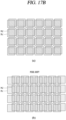
- FIG. 17B is a view of a structure in which pixels are shifted as the glass is adjusted in one axial direction and rotated in another axial direction.
- the PGU 1100 may include a display panel 1110, a prism 1120, a polarization conversion plate 1130, and glass 1140.
- the glass 1140 may be horizontally placed between the polarization conversion plate 1130 and the prism 1120 in the first region Rp1 of the display panel 1110.
- the P-wave that passes through the polarization conversion plate 1130 and the glass 1140 in the first region Rp1 may be reflected from the mirror 1121 and the PBS 1122 and transmitted to the second region Rp2.
- the S-wave passing through the PBS 1122 may be transmitted to the second region Rp2.
- the first pixels Px1 of the first data set and the second pixels Px2 of the second data set may overlap each other in the one axial direction and/or the another axial direction or be spaced apart by a value less than a threshold value.
- the PGU 1100 may include the display panel 1110, the prism 1120, the polarization conversion plate 1130, and the glass 1140.
- the glass 1140 may be tilted (adjusted) by a certain angle relative to a horizontal plane between the polarization conversion plate 1130 and the prism 1120 in the first region Rp1 of the display panel 1110.
- the P-wave that passes through the polarization conversion plate 1130 and the glass 1140 in the first region Rp1 may be reflected from the mirror 1121 and the PBS 1122 and transmitted to the second region Rp2.
- the S-wave passing through the PBS 1122 may be transmitted to the second region Rp2.
- a phase difference may be generated between the P-wave and S-wave as the glass 1140 is tilted (adjusted) by a certain angle relative to the horizontal plane.
- FIG. 17A illustrates a structure in which the glass 1140 is tilted by a certain angle.
- (b) of FIG. 17A illustrates pixels of a data set associated with an optical signal passing through the glass 1140 in a certain region Rc based on a center point of the glass 1140.
- the shift may occur or may be adjusted between the first pixels Px1 of the first data set associated with the P-wave and the second pixels Px2 of the second data set associated with the S-wave.
- the processor 170, 270 may control the tilt angle of the glass 1140 so that the first pixels Px1 of the first data set and the second pixels Px2 of the second data set are sequentially arranged.
- the processor 170, 270 may control the tilt angle of the glass 1140 to increase in case that the shift value of the second pixels Px2 is smaller than or equal to a first threshold value, compared to the first pixels Px1.
- the processor 170, 270 may control the tilt angle of the glass 1140 to decrease in case that the shift value of the second pixels Px2 is greater than or equal to a second threshold value, compared to the first pixels Px1.
- the first threshold value may be set to be smaller than 0.5 pixel
- the second threshold value may be set to be greater than 0.5 pixel.
- an image displayed in a specific region of the windshield by the vehicle imaging device implementing the pixel rearrangement according to the specification may be projected in a wide panel display (WPD) structure, in which a width in one axial direction is greater than or equal to a length in another axial direction by a certain ratio.
- WPD wide panel display
- FIGS. 18A and 18B compare images projected in various forms on a single panel or a dual panel.
- a first image including a first image region IR1 to a third image region IR3 may be displayed on a single panel.
- the first image region IR1 to the third image region IR3 may not be physically separated regions, but may be implemented as virtual image regions displayed on the single panel.
- the single panel may be implemented as a WVGA panel and may have an aspect ratio of, for example, but not limited to, 864 x 480.
- the first image may be displayed at a resolution of 850 x 85, but is not limited to this.
- the first image may be displayed at a resolution of H: 40.0 pixel/° and V: 39.6 pixels/° in the horizontal and vertical axis directions, but is not limited to this.
- a second image including a first image region IR1 to a third image region IR3 may be implemented as an H-compression type in the horizontal axis direction on the single panel.
- the first image may be displayed at a resolution of 850 x 170, but is not limited to this.
- the first image may be displayed at a still low resolution of H: 40.0 pixel/° and V: 79.1 pixel/° in the horizontal and vertical axis directions, but is not limited to this.
- a third image including a first image region IR1 to a third image region IR3 may be displayed on a dual panel.
- the first image region IR1 and a portion of the second image region IR2 may be displayed in the first panel region PR1.
- the remaining portion of the second image region IR2 and the third image region IR3 may be displayed in the second panel region PR2.
- the third image may be displayed at a resolution of H: 80.0 pixel/° and V: 79.1 pixel/° in the horizontal and vertical axis directions, but is not limited to this.
- more information can be provided through an image having a large aspect ratio at a position, which is close to a driver's visual field for driving, in an imaging device having a large aspect ratio for the driver.
- an imaging device implemented by connecting a plurality of image modules can overcome the limitation of natural image implementation due to the lack of continuity at a connection portion of an image.
- a continuous image associated with driving-related information can be implemented using a single image module in a specific region of a windshield in front of a vehicle.
- a vehicle imaging device with a small and thin volume can be provided by using a projection optical system structure having a reflective structure and a screen offset to one side or another side.
Landscapes
- Physics & Mathematics (AREA)
- Engineering & Computer Science (AREA)
- General Physics & Mathematics (AREA)
- Optics & Photonics (AREA)
- Chemical & Material Sciences (AREA)
- Combustion & Propulsion (AREA)
- Transportation (AREA)
- Mechanical Engineering (AREA)
- Manufacturing & Machinery (AREA)
- Instrument Panels (AREA)
- Fittings On The Vehicle Exterior For Carrying Loads, And Devices For Holding Or Mounting Articles (AREA)
Abstract
Description
- This specification relates to a vehicle imaging device. One particular implementation relates to a vehicle imaging device having a large aspect ratio using a projection optical system.
- A vehicle is an apparatus capable of being moved in a desired direction by a user who is on board. A representative example of a vehicle may be an automobile.
- For convenience of a user using a vehicle, various types of sensors and electronic devices are arranged in the vehicle. In particular, for the convenience of the user's driving, research on an advanced driver assistance system (ADAS) is being actively carried out. In addition, an autonomous vehicle is actively under development.
- In some embodiments, a vehicle display that shows various driving information of the vehicle is located below a driver's forward visual field for driving, which affects driving safety, a phenomenon known as rubbernecking. Therefore, a vehicle imaging device, such as a head-up display (HUD), may be mounted on a vehicle to enhance driving safety by projecting an image on a windshield at the front of the vehicle, positioned close to the driver's line of sight while driving.
- An infotainment device also needs to be installed in a passenger or rear seat of the vehicle to provide personal information and personal entertainment content. Therefore, there is a need for a vehicle imaging device that is capable of displaying driving-related information in a front region of a driver's seat of the vehicle or provide personal entertainment content in a front region of a passenger or rear seat of the vehicle.
- To display such driving-related information or entertainment content in a specific region of the windshield at the front of the vehicle, the vehicle imaging device may need to have a large aspect ratio in which a width in one direction is a certain percentage greater than a length in another direction. However, there is a problem in that any position and any structure to provide the vehicle imaging device for constituting a screen with a large aspect ratio in the vehicle are not mentioned.
- An aspect of this specification is to provide a vehicle imaging device having a large aspect ratio using a projection optical system related to the vehicle.
- Another aspect of this specification is to display driving-related information on a screen having a large aspect ratio in a specific region of the windshield at the front of the vehicle.
- Still another aspect of this specification is to provide a vehicle imaging device having an optical structure and a special screen for allowing an image to have a large aspect ratio by using a single image module.
- Still another aspect of this specification is to implement continuous images related to driving-related information to have a large aspect ratio by using a single image module.
- Still another aspect of this specification is to provide a small and thin vehicle imaging device.
- The tasks to be solved in the disclosure may not be limited to the aforementioned, and other problems to be solved by the disclosure will be obviously understood by a person skilled in the art based on the following description.
- In order to achieve those aspects and other advantages according to one or more embodiments, there is a vehicle imaging device including: a cover forming appearance of a dashboard of a vehicle; a picture generation unit (PGU) arranged inside the dashboard and configured to generate light to one side; a screen panel arranged between the PGU and the cover, and configured to reflect light generated by the PGU so that an image by the reflected light passes through the cover; and a mirror arranged on one side of the PGU, and configured to reflect the light generated to the one side so that the reflected light is transmitted to the screen panel, wherein the image by the light reflected from the screen panel may be displayed in a specific region of a windshield of a driver's seat of the vehicle, so that a width of the image in one axial direction is greater than a length in another axial direction.
- In an embodiment, the PGU and the mirror may be arranged on a left side of the screen panel. The screen panel may have an inclined structure in which a vertical distance to the cover decreases from left to right. The light generated by the PGU may be reflected from the first mirror, the second mirror, and the screen panel, and diffuse in a certain angular range based on a direction perpendicular to the cover.
- In an embodiment, the PGU and the mirror may be arranged on a right side of the screen panel. The screen panel may have an inclined structure in which a vertical distance to the cover increases from left to right. The light generated by the PGU may be reflected from the first mirror, the second mirror, and the screen panel, and diffuse in a certain angular range based on a direction perpendicular to the cover.
- In an embodiment, the mirror may include: a first mirror arranged on one side of the PGU and configured to change an optical path by reflecting the light generated to the one side; and a second mirror configured to reflect the light reflected from the first mirror to be transmitted to the screen panel. One surface of the first mirror, onto which the light generated by the PGU is incident, may be formed in a plane shape by being tilted to one side by a first angle relative to the incident light. One surface of the second mirror, onto which the light reflected from the first mirror is incident, may be formed in a curved shape by being tilted to another side by a second angle. The second angle may be set to be smaller than the first angle.
- In an embodiment, the screen panel may be formed inside the dashboard to have a first width in one axial direction and a first length in another axial direction. A ratio of the first width and the first length may be set to a first ratio. A ratio of the width and the length of the image displayed on the windshield may be set to a second ratio. A top of the image displayed on the windshield may be positioned lower than a center line of the windshield. The first and second ratios may be set to be at least 5:1.
- In an embodiment, the screen panel may include: a reflective layer including patterns formed in the another axial direction and arranged spaced apart in the one axial direction and configured to reflect the light generated by the PGU; and a diffusion layer arranged on one surface of the reflective layer and configured to diffuse the light reflected from the reflective layer in a certain angular range based on the direction perpendicular to the cover. The patterns may be arranged such that a spaced distance between the patterns of the reflective layer decreases as a vertical distance from the screen panel to the cover decreases.
- In an embodiment, the PGU may include: a display panel; a prism arranged spaced apart from the display panel and including a mirror and a polarization beam splitter (PBS) formed therein; a polarization conversion plate arranged parallel to the display panel between the display panel and the prism; and a projection lens including a plurality of lenses arranged spaced apart from the prism.
- In an embodiment, the display panel may include a first region corresponding to a region where the polarization conversion plate and the mirror are arranged, and a second region corresponding to a region where the PBS is arranged. One end of the polarization conversion plate may correspond to one end of the display panel. Another end of the polarization conversion plate may correspond to a center of the display panel.
- In an embodiment, an S-wave passing through the polarization conversion plate in the first region may be reflected from the mirror and the PBS to be incident onto the projection lens. A P-wave output in the second region may pass through the PBS to be incident onto the projection lens. The prism may include a first absorbing layer attached to upper and side surfaces of the prism corresponding to the first region or a second absorbing layer attached to upper and side surfaces of the prism corresponding to the second region.
- In an embodiment, the PGU may include: a display panel configured to radiate a P-polarized signal; a prism arranged spaced apart from the display panel and including a mirror and a half mirror arranged therein; and a projection lens including a plurality of lenses arranged spaced apart from the prism. P-polarized signals radiated from a first region, which is one side of the display panel, may be all reflected from the mirror and reflected by a certain percentage from the half mirror to be incident onto the projection lens. A remaining percentage of the P-polarized signal passed through the half mirror, of P-polarized signals radiated from the second region, which is another side of the display panel, may be incident onto the projection lens.
- In an embodiment, the PGU may include: a display panel; a lower prism arranged spaced apart from the display panel and having a certain height; a prism arranged above the lower prism, and including therein a first PBS and a second PBS; and a projection lens including a plurality of lenses arranged spaced apart from the prism.
- In an embodiment, the display panel may include a first region corresponding to a region where the first PBS is arranged, and a second region corresponding to a region where the second PBS is arranged. An upper end of the first PBS may correspond to a center of the display panel. A lower end of the second PBS may correspond to the center of the display panel.
- In an embodiment, the first PBS may be implemented as a mirror. The prism may include an absorbing layer attached to upper and side surfaces of the prism corresponding to the second region. A P-wave of an optical signal output to the first region may be reflected from the mirror arranged in the first region of the prism and may pass through the second PBS to be absorbed by the absorbing layer. An S-wave of the optical signal output to the first region may be reflected from the mirror and reflected from the second PBS to be incident onto the projection lens.
- In an embodiment, an S-wave reflected from the second PBS, of an optical signal output to the second region, may be absorbed by the absorbing layer. A P-wave passing through the second PBS, of the optical signal output to the second region, may be incident onto the projection lens.
- In an embodiment, the prism may include a first absorbing layer attached to upper and side surfaces of the prism corresponding to the first region, and a second absorbing layer attached to upper and side surfaces of the prism corresponding to the second region. A P-wave of an optical signal output to the first region may pass through the first PBS arranged in the first region to be absorbed by the first absorbing layer. An S-wave of the optical signal output to the first region may be reflected from the first PBS and the second PBS to be incident onto the projection lens.
- In an embodiment, an S-wave reflected from the second PBS, of an optical signal output to the second region, may be absorbed by the second absorbing layer. A P-wave passing through the second PBS, of the optical signal output to the second region, may be incident onto the projection lens.
- In an embodiment, the PGU may include: a display panel configured to radiate an unpolarized signal; a lower prism arranged spaced apart from the display panel and having a certain height; a prism arranged above the lower prism and comprising a mirror and a half mirror arranged therein; and a projection lens including a plurality of lenses arranged spaced apart from the prism. Unpolarized signals radiated from a first region, which is one side of the display panel, may be all reflected from the mirror and reflected by a certain percentage from the half mirror to be incident onto the projection lens. A remaining percentage of the unpolarized signal passed through the half mirror, of unpolarized signals radiated from the first region, which is another side of the display panel, may be incident onto the projection lens.
- In an embodiment, the PGU may further include a second polarization conversion plate attached to an upper portion of the prism between the mirror and the PBS or attached to an upper portion of the prism between the first PBS and the second PBS and configured to synthesize the P-wave with the S-wave.
- In an embodiment, the vehicle imaging device may further include a processor arranged in the vehicle and configured to control data included in an optical signal output from the PGU. The processor may control the PGU so that a first data set having a shape of the P-wave and a second data set having a shape of the S-wave are arranged alternately.
- In an embodiment, the processor may control a first data set and a second data set to be alternately arranged in the one axial direction by inserting second data of the second data set between adjacent data constituting the first data set. The processor may display the image, which is implemented by the first data set and the second data set arranged alternately, in the specific region.
- In an embodiment, the PGU may further include glass tiltably arranged between the polarization conversion plate and the prism in the first region of the display panel. The processor may control a tilt angle of the glass so that first pixels of the first data set and second pixels of the second data set are sequentially arranged.
- In an embodiment, the processor may increase the tilt angle of the glass in case that a shift value of the second pixels, compared to the first pixels, is smaller than or equal to a first threshold value. The processor may decrease the tilt angle of the glass in case that a shift value of the second pixels, compared to the first pixels, is greater than or equal to a second threshold value. The first threshold value may be set to be smaller than 0.5 pixel, and the second threshold value may be set to be greater than 0.5 pixel.
- A projector according to another aspect of the specification includes a picture generation unit (PGU) arranged inside the projector and configured to generate light to one side; and a processor operatively coupled to the PGU and configured to control the PGU such that a first data set and a second data set are arranged alternately. The processor may control the first data set and the second data set to be alternately arranged in one axial direction by inserting second data of the second data set between adjacent data constituting the first data set, and control an image implemented by the first data set and the second data set arranged alternately to be displayed in a specific region.
- Details of other embodiments are included in the detailed description and drawings.
- The technical features of a vehicle imaging device having a large aspect ratio using a projection optical system according to the specification will be summarized as follows.
- According to the specification, more information can be provided through an image having a large aspect ratio at a position, which is close to a driver's visual field for driving, in an imaging device having a large aspect ratio for the driver.
- According to the specification, an imaging device implemented by connecting a plurality of image modules can overcome the limitation of natural image implementation due to the lack of continuity at a connection portion of an image.
- According to the specification, a continuous image associated with driving-related information can be implemented using a single image module in a specific region of a windshield in front of a vehicle.
- According to the specification, a vehicle imaging device having a small and thin volume can be provided by using a projection optical system structure having a reflective structure and a screen panel offset to one side or another side.
- According to the specification, a vehicle imaging device with a thin and small volume can be implemented using an ultra short throw (UST) projector and a special screen in a limited space inside a vehicle where a steering wheel, pedals, or CQT are placed.
- The effects of the disclosure are not limited to those effects mentioned above, and other effects not mentioned may be clearly understood by those skilled in the art from the description of the appended claims.
-
-
FIG. 1 is a view illustrating appearance of a vehicle according to an embodiment. -
FIG. 2 is a diagram illustrating appearance of a vehicle at various angles according to an embodiment. -
FIGS. 3 and4 are diagrams illustrating an inside of a vehicle according to an embodiment. -
FIG. 5 is a block diagram illustrating a vehicle according to an embodiment. -
FIG. 6A is a view of a configuration in which a screen of a certain ratio is formed in a specific region of front glass of a vehicle. -
FIG. 6B is a view of a structure in which a vehicle imaging device for creating the screen of the certain ratio ofFIG. 6A is arranged inside a dashboard of the vehicle. -
FIG. 7 is a view of a structure in which a picture generation unit and internal components of the vehicle imaging device ofFIG. 6B are arranged inside a cover. -
FIG. 8A is a view of a structure in which the picture generation unit is arranged on a left side of a screen panel in the vehicle imaging device ofFIG. 7 . -
FIG. 8B is a view of a structure in which the picture generation unit is arranged on a right side of the screen panel in the vehicle imaging device ofFIG. 7 . - FIG. 9A is a view of a structure in which a screen panel of a vehicle imaging device according to this specification includes a plurality of layers.
- FIG. 9B is a view of a fresnel structure of a reflective layer of a screen panel according to this specification.
-
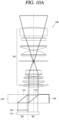
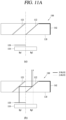
FIGS. 10A and10B are views of embodiments in which a prism structure and a projection lens structure are arranged above a display panel. - FIGS. 11A and 11B are views of P-wave and S-wave optical signals in a PGU structure having a single PBS structure and a PGU structure having a double PBS structure, in the structure of
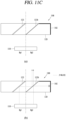
FIG. 10A . - FIG. 11C is a view of P-polarized signals in mirror-type and half mirror-type PGU structures in the structure of
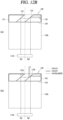
FIG. 10A . - FIGS. 12A and 12B are views of P-wave and S-wave optical signals in a PGU structure having a single PBS structure and a PGU structure having a double PBS structure, in the structure of
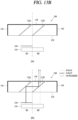
FIG. 10B . - FIG. 12C is a view of an unpolarized signal in mirror-type and half mirror-type PGU structures in the structure of
FIG. 10A . - FIGS. 13A and 13B are views of a structure in which a second polarization conversion plate is further attached to an upper portion of a prism in FIGS. 11A and 11B.
- FIGS. 14A and 14B are views of a structure in which a second polarization conversion plate is further attached to an upper portion of a prism in FIGS. 12A and 12B.
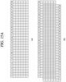
- FIG. 15A compares images generated by first and second systems that do not perform pixel rearrangement.
- FIG. 15B compares screens enlarged in one axial direction in the first and second systems of FIG. 15A.
-
FIG. 15C is a view of a configuration of a projector, which is an imaging device that performs pixel rearrangement. - FIGS. 16A and 16B compare structures of a PGU having a glass rotatable in one axial direction before and after the glass is rotated.
- FIG. 17A is a view of a structure in which the glass of FIG. 16B is tilted by a certain angle and a pixel adjustment principle according to the structure.
- FIG. 17B is a view of a structure in which pixels are shifted as the glass is adjusted in one axial direction and rotated in another axial direction.
- FIGS. 18A and
18B compare images implemented in various shapes on a single panel or a dual panel. - Description will now be given in detail according to one or more embodiments disclosed herein, with reference to the accompanying drawings. For the sake of brief description with reference to the drawings, the same or equivalent components may be provided with the same or similar reference numbers, and description thereof will not be repeated. The terms "module" and "unit" as used herein interchangeably or individually used to refer to a constituent element only for convenience in description in the specification and therefore are not themselves intended to take on different meanings or to depict different functions. In describing one or more embodiments disclosed herein, a detailed description of a related well-known technology will be omitted when it is determined that it would obscure the gist of the disclosure. The accompanying drawings are used to help easily understand the technical idea of the disclosure and it should be understood that the idea of the disclosure is not limited by the accompanying drawings. The idea of the disclosure should be construed to extend to any alterations, equivalents, and substitutes besides the accompanying drawings.
- The terms including an ordinal number such as first, second, and the like may be used to describe various elements, but the elements should not be limited by those terms. The terms are used merely for the purpose of distinguishing one element from another.
- It will be understood that when an element is referred to as being "connected with" another element, the element may be connected with the another element or intervening elements may also be present. In contrast, when an element is referred to as being "directly connected with" another element, there are no intervening elements present.
- As used herein, the singular form is intended to include the plural forms as well, unless context clearly indicates otherwise.
- In the present application, it should be further understood that the terms "comprises," "includes," etc. specify the presence of stated features, integers, steps, operations, elements, components, or combinations thereof, but do not preclude the presence or addition of one or more other features, integers, steps, operations, elements, components, or combinations thereof.
- A vehicle according to an embodiment of the disclosure may be understood as a conception including automobiles, motorcycles, and the like. Hereinafter, the vehicle will be described based on a car.
- The vehicle according to the embodiment of the disclosure may be a conception including all of an internal combustion engine car having an engine as a power source, a hybrid vehicle having an engine and an electric motor as power sources, an electric vehicle having an electric motor as a power source, and the like.
- In the following description, a left side of a vehicle refers to a left side in a driving direction of the vehicle, and a right side of the vehicle refers to a right side in the driving direction.
-
FIG. 1 is a view illustrating appearance of a vehicle according to an embodiment. -
FIG. 2 is a diagram illustrating the appearance of the vehicle at various angles. -
FIGS. 3 and4 are diagrams illustrating an inside of a vehicle according to an embodiment. -
FIG. 5 is a block diagram illustrating a vehicle according to an embodiment. - As illustrated in
FIGS. 1 to 5 , avehicle 100 may include wheels rotating by a power source, and asteering input apparatus 510 for adjusting a driving (ongoing, moving) direction of thevehicle 100. - The
vehicle 100 may be an autonomous vehicle. - The
vehicle 100 may be switched into an autonomous mode or a manual mode based on a user input. - For example, the
vehicle 100 may be converted from the manual mode into the autonomous mode or from the autonomous mode into the manual mode based on a user input received through auser interface device 200. - The
vehicle 100 may be switched into the autonomous mode or the manual mode based on traveling situation information. The traveling situation information may be generated based on object information provided from anobject detection device 300. - For example, the
vehicle 100 may be switched from the manual mode into the autonomous mode or from the autonomous module into the manual mode based on traveling situation information generated in theobject detection device 300. - In an example, the
vehicle 100 may be switched from the manual mode into the autonomous mode or from the autonomous mode into the manual mode based on traveling situation information received through acommunication device 400. - The
vehicle 100 may be switched from the manual mode into the autonomous mode or from the autonomous module into the manual mode based on information, data or signal provided from an external device. - When the
vehicle 100 is driven in the autonomous mode, thevehicle 100 may be driven based on adriving system 700. - For example, the
autonomous vehicle 100 may be driven based on information, data, or signals that are generated by a travelingsystem 710, a parking-lot departure system 740, and aparking system 750. - When the
vehicle 100 is driven in the manual mode, theautonomous vehicle 100 may receive a user input for driving through a drivingoperation device 500. Thevehicle 100 may be driven based on the user input received through the drivingoperation device 500. - An overall length refers to a length from a front end to a rear end of the
vehicle 100, a width refers to a width of thevehicle 100, and a height refers to a length from a bottom of a wheel to a roof. In the following description, an overall-length direction L may refer to a direction which is a criterion for measuring the overall length of thevehicle 100, a width direction W may refer to a direction that is a criterion for measuring a width of thevehicle 100, and a height direction H may refer to a direction that is a criterion for measuring a height of thevehicle 100 - As illustrated in
FIG. 5 , thevehicle 100 may include auser interface device 200, anobject detection device 300, acommunication device 400, a drivingoperation device 500, avehicle drive device 600, adriving system 700, anavigation system 770, asensing unit 120, aninterface unit 130, amemory 140, acontroller 170, and apower supply unit 190. - According to embodiments, the
vehicle 100 may include more components in addition to components to be explained in this specification or may not include some of those components to be explained in this specification. - The
user interface device 200 is a device for communication between thevehicle 100 and a user. Theuser interface device 200 may receive a user input and provide information generated in thevehicle 100 to the user. Thevehicle 100 may implement user interfaces (Uls) or user experiences (UXs) through theuser interface device 200. - The
user interface device 200 may include aninput unit 210, aninternal camera 220, abiometric detection unit 230, anoutput unit 250, and aprocessor 270. - According to embodiments, the
user interface device 200 may include more components in addition to components to be explained in this specification or may not include some of those components to be explained in this specification. - The
input unit 200 may allow the user to input information. Data collected in theinput unit 120 may be analyzed by theprocessor 270 and processed as a user's control command. - The
input unit 200 may be disposed inside the vehicle. For example, theinput unit 200 may be disposed on one region of a steering wheel, one region of an instrument panel, one region of a seat, one region of each pillar, one region of a door, one region of a center console, one region of a headlining, one region of a sun visor, one region of a windshield, one region of a window, or the like. - The
input unit 200 may include avoice input part 211, agesture input part 212, atouch input part 213, and amechanical input part 214. - The
audio input part 211 may convert a user's voice input into an electric signal. The converted electric signal may be provided to theprocessor 270 or thecontroller 170. - The
audio input part 211 may include at least one microphone. - The
gesture input part 212 may convert a user's gesture input into an electric signal. The converted electric signal may be provided to theprocessor 270 or thecontroller 170. - The
gesture input part 212 may include at least one of an infrared sensor and an image sensor for detecting the user's gesture input. - According to embodiments, the
gesture input part 212 may detect a user's three-dimensional (3D) gesture input. To this end, thegesture input part 212 may include a light-emitting diode outputting a plurality of infrared rays or a plurality of image sensors. - The
gesture input part 212 may detect the user's 3D gesture input by a time of flight (TOF) method, a structured light method or a disparity method. - The
touch input part 213 may convert the user's touch input into an electric signal. The converted electric signal may be provided to theprocessor 270 or thecontroller 170 - The
touch input part 213 may include a touch sensor for detecting the user's touch input. - According to an embodiment, the
touch input part 213 may be integrated with thedisplay 251 so as to implement a touch screen. The touch screen may provide an input interface and an output interface between thevehicle 100 and the user. - The
mechanical input part 214 may include at least one of a button, a dome switch, a jog wheel, and a jog switch. An electric signal generated by themechanical input part 214 may be provided to theprocessor 270 or thecontroller 170. - The
mechanical input part 214 may be arranged on a steering wheel, a center fascia, a center console, a cockpit module, a door, and the like. - The
internal camera 220 may acquire an internal image of the vehicle. Theprocessor 270 may detect a user's state based on the internal image of the vehicle. Theprocessor 270 may acquire information related to the user's gaze from the internal image of the vehicle. Theprocessor 270 may detect a user gesture from the internal image of the vehicle. - The
biometric detection unit 230 may acquire the user's biometric information. Thebiometric detection unit 230 may include a sensor for detecting the user's biometric information and acquire fingerprint information and heart rate information regarding the user using the sensor. The biometric information may be used for user authentication. - The
output unit 250 may generate an output related to a visual, auditory, or tactile signal. - The
output unit 250 may include at least one of adisplay 251, anaudio output part 252, and ahaptic output part 253. - The
display 251 may output graphic objects corresponding to various types of information. - The
display 251 may include at least one of a liquid crystal display (LCD), a thin film transistor-LCD (TFT LCD), an organic light-emitting diode (OLED), a flexible display, a three-dimensional (3D) display and an e-ink display. - The
display 251 may be inter-layered or integrated with atouch input part 213 to implement a touch screen. - The
display 251 may be implemented as a head up display (HUD), a center information display (CID), a cluster, and/or a rear seat entertainment (RSE). When thedisplay 251 is implemented as the HUD, thedisplay 251 may be provided with a projection module and thus output information through an image which is projected onto a windshield or a window. - The
display 251 may include a transparent display. The transparent display may be attached to the windshield or the window. - The transparent display may have a predetermined degree of transparency and output a predetermined screen thereon. The transparent display may include at least one of a thin film electroluminescent (TFEL), a transparent organic light-emitting diode (OLED), a transparent liquid crystal display (LCD), a transmissive transparent display, or a transparent LED display. The transparent display may have adjustable transparency.
- In some examples, the
user interface device 200 may include a plurality ofdisplays 251a to 251g. - The
display 251 may be arranged in one region of the steering wheel, oneregion 521a, 251b, 251e of the instrument panel, oneregion 251d of the seat, oneregion 251f of each pillar, oneregion 251g of the door, one region of the center console, one region of the headlining, or one region of the sun visor, or implemented in oneregion 251c of the windshield or oneregion 251h of the window. - Driving-related information for a driver may be displayed in one
region 251a, 251b of the instrument panel. A personal infotainment display may be implemented in oneregion 251e of the instrument panel by a vehicle imaging device for a passenger seated in a front passenger seat. A personal infotainment display may be implemented in oneregion 251d of the seat by a vehicle imaging device for rear seat entertainment (RSE). - The
audio output part 252 may convert an electric signal provided by theprocessor 270 or thecontroller 170 into an audio signal and output the audio signal. To this end, theaudio output part 252 may include at least one speaker. - The
haptic output part 253 may generate a tactile output. For example, thehaptic output part 253 may vibrate the steering wheel, a safety belt, a seat 110FL, 110FR, 110RL, 110RR such that the user can recognize such output. - The
processor 270 may control an overall operation of each unit of theuser interface device 200. - According to an embodiment, the
user interface device 200 may include a plurality ofprocessors 270 or may not include anyprocessor 270. - When the
processor 270 is not included in theuser interface device 200, theuser interface device 200 may operate according to a control of a processor of another device within thevehicle 100 or thecontroller 170. - In some embodiments, the
user interface device 200 may be named a display device for vehicle. - The
user interface device 200 may operate under the control of thecontroller 170. - The
object detection device 300 is a device for detecting an object located outside thevehicle 100. - Examples of the object may include a variety of objects associated with driving (operation) of the
vehicle 100. - In some embodiments, a vehicle imaging device according to this specification will be described. In some embodiments, a vehicle display that shows various driving information related to a vehicle may be located below a driver's forward visual field for driving, which affects driving safety (rubbernecking). Therefore, a vehicle imaging device, such as a head-up display (HUD), may be mounted on a vehicle to enhance driving safety by projecting an image on a windshield at the front of the vehicle, positioned close to the driver's line of sight while driving.
- An infotainment device also needs to be installed in a passenger or rear seat of the vehicle to provide personal information and personal entertainment content. Therefore, there is a need for a vehicle imaging device that is capable of displaying driving-related information in a front region of a driver's seat of the vehicle or provide personal entertainment content in a front region of a passenger or rear seat of the vehicle.
- To display such driving-related information or entertainment content in a specific region of the windshield at the front of the vehicle, the vehicle imaging device may need to have a large aspect ratio in which a width in one direction is a certain percentage greater than a length in another direction. However, there is a problem in that any position and any structure to provide the vehicle imaging device for constituting a screen with a large aspect ratio in the vehicle are not mentioned.
- To solve these problems, an aspect of this specification is to provide a vehicle imaging device having a large aspect ratio using a projection optical system related to the vehicle. Another aspect of this specification is to display driving-related information on a screen having a large aspect ratio in a specific region of the windshield at the front of the vehicle. Still another aspect of this specification is to provide a vehicle imaging device having an optical structure and a special screen for allowing an image to have a large aspect ratio by using a single image module. Still another aspect of this specification is to implement continuous images related to driving-related information to have a large aspect ratio by using a single image module. Still another aspect of this specification is to provide a small and thin vehicle imaging device.
- Hereinafter, a vehicle imaging device for achieving the aforementioned purposes will be described in detail with reference to the drawings. In this regard,
FIG. 6A is a view of a configuration in which a screen of a certain ratio is formed in a specific region of front glass of a vehicle.FIG. 6B is a view of a structure in which a vehicle imaging device for creating the screen of the certain ratio ofFIG. 6A is arranged inside a dashboard of the vehicle. - In some embodiments,
FIG. 7 is a view of a structure in which a picture generation unit and internal components of the vehicle imaging device ofFIG. 6B are arranged inside a cover.FIG. 8A is a view of a structure in which the picture generation unit is arranged on a left side of a screen panel in the vehicle imaging device ofFIG. 7 .FIG. 8B is a view of a structure in which the picture generation unit is arranged on a right side of the screen panel in the vehicle imaging device ofFIG. 7 . - Referring to
FIG. 6A , an image having a width Wa in one axial direction and a length La in another axial direction may be displayed in aspecific region 251R of a windshield of a vehicle. The image may be configured to include a plurality of image regions displaying information necessary for driving the vehicle. The plurality of image regions may include a first image region IR1 to a third image region IR3. A first image including vehicle-related information may be displayed in the first image region IR1 closest to a driver's visual field range in the vehicle. A second image associated with a vehicle driving path may be displayed in the second image region IR2. A third image associated with a map including an origin and a destination may be displayed in the third image region IR3. As the plurality of images are displayed in thespecific region 251R, the width Wa in the one axial direction may be set to be longer than the length La in the another axial direction by a certain ratio, for example, at least 5 times. - Referring to
FIGS. 6A and6B , avehicle imaging device 1000 may be arranged inside the dashboard of the vehicle. Thevehicle video device 1000 may be arranged in a specific region inside the dashboard not to overlap a region where a steering wheel and pedals are arranged. An image by light, which is reflected from ascreen panel 1200 constituting thevehicle imaging device 1000, may be displayed in thespecific region 251R of the windshield of the vehicle. Thespecific region 251R may be implemented with a certain length La so that the image is displayed in the driver's visual field range. A distance from a center of the driver's gaze to a center of thespecific region 251R may be defined as a certain distance, for example, approximately 1.2 m. - Referring to
FIGS. 6A to 8B , thevehicle imaging device 1000 may be configured to include acover 1010, apicture generation unit 1100, ascreen panel second mirror first mirror 1310a and asecond mirror 1320a. The mirror 1300 may alternatively be configured to include only one of afirst mirror 1310 and asecond mirror 1320. - As another example, the mirror 1300 may be configured to include a
first mirror second mirror cover 1010 may form the appearance of the dashboard of the vehicle. Thepicture generation unit 1100, thescreen panel first mirror second mirror cover 1010. - In some embodiments, the
cover 1010 of thevehicle imaging device 1000 according to the specification may include a transmission region (or transparent region) through which optical signals including images are transmitted, and a non-transmission region (or opaque region) in which internal components are arranged. Referring toFIG. 7 , thecover 1010 may include anopaque region 1010a and a transparent region 1010b. - Referring to
FIGS. 6A to 8B , theopaque region 1010a may be formed in one side region and/or another side region corresponding to regions where thepicture generation unit 1100 and the first andsecond mirrors screen panel 1200 is arranged. Theopaque region 1010a may be formed to surround the transparent region 1010b. An image formed by reflection from thescreen panel 1200 may pass through the transparent region 1010b of thecover 1010 to be displayed in thespecific region 251R of the windshield in a passenger seat. - A picture generation unit (PGU) 1100 may be arranged inside the dashboard and configured to generate light to one side. The
screen panel picture generation unit 1100 and thecover 1010. Thescreen panel picture generation unit 1100 so that an image by the reflected light passes through thecover 1010. - The mirror 1300 may be arranged on one side or another side of the
picture generation unit 1100. The mirror 1300 may be configured to reflect light emitted to one side and transmit the light to thescreen panel 1200. Themirror screen panel 1200. - The
first mirror picture generation unit 1100. Thefirst mirror picture generation unit 1100. Thesecond mirror first mirror screen panel second mirror first mirror screen panel screen panel specific region 251R of the windshield of the vehicle in a manner that a width Wa of the image in one axial direction is greater than a length La in another axial direction. Thespecific region 251R of the windshield may be a region within the driver's visual field range in the vehicle. - Referring to
FIG. 8A , thepicture generation unit 1100 and themirror 1320a may be arranged on a left side which is one side of thescreen panel 1200a. Thepicture generation unit 1100, thefirst mirror 1310a, and thesecond mirror 1320a may be arranged on the left side which is the one side of thescreen panel 1200a. Thescreen panel 1200a may be formed with a tilted structure in which a vertical distance to thecover 1010 decreases from left to right. Thescreen panel 1200a may be formed to have a positive slope from left to right. Light emitted from thepicture generation unit 1100 may be reflected by thefirst mirror 1310a, thesecond mirror 1320a, and thescreen panel 1200a, and may disperse within a certain angular range based on a direction perpendicular to thecover 1010. - Referring to
FIGS. 7 and8B , thepicture generation unit 1100 and themirror 1320 may be arranged on the right side which is another side of thescreen panel 1200. Thepicture generation unit 1100, thefirst mirror 1310, and thesecond mirror 1320 may be arranged on the right side which is the another side of thescreen panel 1200. Thescreen panel 1200 may be formed to have a negative slope from left to right. Thescreen panel 1200 may be formed with a tilted structure in which a vertical distance to thecover 1010 increases from left to right. Light emitted from thepicture generation unit 1100 may be reflected by thefirst mirror 1310, thesecond mirror 1320, and thescreen panel 1200, and may diffuse within a certain angular range based on the direction perpendicular to thecover 1010. - Referring to
FIGS. 6 to 8B , thescreen panel - In some embodiments, in the vehicle imaging device according to the specification, the screen panel may include a plurality of layers. In this regard, FIG. 9A is a view of a structure in which a screen panel of a vehicle imaging device according to this specification includes a plurality of layers.
- Referring to
FIG. 7 through (a) of FIG. 9A, areflective layer 1210 of thescreen panel 1200 may havepatterns 1212 arranged with being spaced apart from each other. Thepatterns 1212 of thereflective layer 1210 may constitute a partial area of an ellipse formed in one and another axial directions. Thepatterns 1212 of thereflective layer 1210 may be arranged spaced apart in the another axial direction. - Referring to
FIG. 7 through (b) of FIG. 9B, thescreen panel 1200 may be configured to include areflective layer 1210 and adiffusion layer 1220. Thereflective layer 1210 may have a fresnel structure and may also be referred to as a fresnel layer. Thereflective layer 1210 may be arranged so that the patterns formed in the another axial direction are spaced apart in the one axial direction. Thediffusion layer 1220 may be arranged on one surface of thereflective layer 1210. A rear surface of thediffusion layer 1220 may be attached to the one surface of thereflective layer 1210. - FIG. 9B is a view of a fresnel structure of a reflective layer of a screen panel according to this specification. (a) of FIG. 9B is a cross-sectional view of the
reflective layer 1210 of the screen panel. Referring to (a) of FIG. 9B, thereflective layer 1210 of the screen panel may be formed to have a certain depth Dp. Thereflective layer 1210 may includefirst patterns 1211 in a first region 1210-R1 andsecond patterns 1212 in a second region 1210-R2. Thefirst patterns 1211 may be formed as metal patterns and configured to reflect light. Thesecond patterns 1212 may be formed as metal patterns or as non-metal patterns. - Referring to FIGS. 7 to 9B, light incident from the mirror 1300 in a desired direction may be reflected from the
first patterns 1211. In another example, light incident in an undesired direction may be absorbed by thesecond patterns 1212 formed as the non-metal patterns. Accordingly, the light incident in the undesired direction may not be reflected from thereflective layer 1210 of the screen panel, thereby improving quality of the image displayed on the windshield. - In the first region 1210-R1, the
reflective layer 1210 may be formed as thefirst pattern 1211 having a first slope angle. In the second region 1210-R2, thereflective layer 1210 may be formed as thesecond pattern 1212 having a second slope angle greater than the first slope angle. Thereflective layer 1210 may be formed in a structure in which thefirst pattern 1211 of the first region 1210-R1 and thesecond pattern 1212 of the second region 1210-R2 are repeatedly formed. Referring toFIGS. 7 ,10A , and10B , the patterns may be arranged such that a spacing between thepatterns reflective layer 1210 decreases as a vertical distance from thescreen panel 1200 to thecover 1010 decreases. - The
first pattern 1211 may be formed in a certain linear shape or parabolic shape. - (b) of FIG. 9B shows elliptical structures of upper and lower surfaces of the
reflective layer 1210 of the screen panel and thesecond pattern 1212 on a side surface of thereflective layer 1210. Referring to (b) of FIG. 9B, afirst boundary region 1211b formed on the upper surface of thereflective layer 1210 may be referred to as a peak structure. Thefirst boundary region 1211b may have an elliptical structure. Thefirst boundary region 1211b having the elliptical structure may be formed as bp 2x2+ap 2y2 - ap 2bp 2=0. In this regard, ap denotes an x value of a peak at y=0 and bp denotes a y value of the peak at x=0. A third metal pattern 1213 formed on the lower surface may be referred to as a valley structure. Asecond boundary region 1212b may also have the elliptical structure. Thesecond boundary region 1212b having the elliptical structure may be formed as bv 2x2+av 2y2 - av 2bv 2=0. In this regard, av denotes an x value of a valley at y=0, and bv denotes a y value of the valley at x=0. - Referring to FIGS. 6A to 9B, the
reflective layer 1210 may havepatterns 1211 formed to reflect light emitted from thepicture generation unit 1100. Thepatterns 1211 may have a cross-section that is linear or parabolic and a front surface that is formed in an elliptical shape. Thediffusion layer 1220 may be arranged on one surface of thereflective layer 1210, and may be configured so that light reflected from thereflective layer 1210 is diffused within a certain angular range based on the direction perpendicular to thecover 1010. Thepatterns 1211 may be formed such that lengths L1a, L1b, and L1c of thepatterns 1211 of thereflective layer 1210 in the one axial direction decrease as a vertical distance from thescreen panel 1200 to thecover 1010 decreases. The first slope angle of thepatterns 1211 of thereflective layer 1210 may increase as the vertical distance from thescreen panel 1200 to thecover 1010 decreases. - The
reflective layer 1210 may includefirst patterns 1211 andsecond patterns 1212. Thefirst patterns 1211 may have a cross-section formed in a linear or parabolic shape having a first slope angle and a front surface formed in an elliptical shape, and may be configured to reflect light. Thesecond patterns 1212 may be arranged between thefirst patterns 1211. Thesecond patterns 1212 may be formed in a linear or parabolic shape to have a second slope angle greater than the first slope angle of thefirst patterns 1211. Thefirst patterns 1211 of thereflective layer 1210 in one side region where thepicture generation unit 1100 is arranged may have a length that is longer than a length of thefirst patterns 1211 of thereflective layer 1210 in another side region. - In some embodiments, in the vehicle imaging device according to the specification, a picture generation unit PGU may produce an image through a prism structure and a projection lens structure arranged in the front surface of the display panel, so that the image may be displayed in a specific region of the windshield. In this regard,
FIGS. 10A and10B are views of embodiments in which a prism structure and a projection lens structure are arranged above a display panel. - FIGS. 11A and 11B are views of P-wave and S-wave optical signals in a PGU structure having a single PBS structure and a PGU structure having a double PBS structure, in the structure of
FIG. 10A . FIG. 11C is a view of P-polarized signals in mirror-type and half mirror-type PGU structures in the structure ofFIG. 10A . - Referring to FIGS. 10A to 11C, a picture generation unit (PGU) 1100 may include a
display panel 1110, aprism 1120, apolarization conversion plate 1130, and aprojection lens 1150. Thedisplay panel 1110 may have an LCD structure. Theprism 1120 may be arranged spaced apart from thedisplay panel 1110. - Referring to
FIGS. 10A and 11A, theprism 1120 may include amirror 1121 and a polarization beam splitter (PBS) 1122 arranged therein. Referring to FIG. 11B, theprism 1120 may include afirst PBS 1122a and asecond PBS 1122 arranged therein. - Referring to FIGS. 10A to 11B, the
polarization conversion plate 1130 may be arranged between thedisplay panel 1110 and theprism 1120 to be parallel to thedisplay panel 1110. Thepolarization conversion plate 1130 may be configured as a half-wave plate. Theprojection lens 1150 may include a plurality of lenses spaced apart from theprism 1120. - The
display panel 1110 may include a first region Rp1 and a second region Rp2. The first region Rp1 may correspond to a region where thepolarization conversion plate 1130 and the mirror 1121 (or thefirst PBS 1122a) are arranged. The second region Rp2 may correspond to a region where thePBS 1122 is arranged. One end of thepolarization conversion plate 1130 may correspond to one end of thedisplay panel 1110. Another end of thepolarization conversion plate 1130 may correspond to the center of thedisplay panel 1110. - An S-wave that passes through the
polarization conversion plate 1130 in the first region Rp1 may be reflected from the mirror 1121 (or thefirst PBS 1122a) and thePBS 1122 to be incident onto theprojection lens 1150. A P-wave output from the second region Rp2 may pass through thePBS 1122 to be incident onto theprojection lens 1150. Theprism 1120 may include afirst absorption layer 1161 attached to upper and side surfaces of theprism 1120 corresponding to the first region Rp1. Theprism 1120 may include asecond absorption layer 1162 attached to upper and side surfaces of theprism 1120 corresponding to the second region Rp2. Ends of thefirst absorption layer 1161 and thesecond absorption layer 1162 may extend up to points, at which upper ends of the mirror 1121 (or thefirst PBS 1122a) and thePBS 1122 are located, respectively. Accordingly, a first length of a side portion of thefirst absorption layer 1161 may be longer than a second length of a side portion of thesecond absorption layer 1162. - Referring to
FIGS. 10A and 11C, theprism 1120 may include amirror 1121 and ahalf mirror 1121b arranged inside. Themirror 1121 may be configured as a full mirror that reflects all of optical signals. Thehalf mirror 1121b may be configured to reflect a certain percentage (e.g., 50%) of optical signals. Thehalf mirror 1121b may be configured to reflect a certain percentage of optical signals and allow the remaining percentage of optical signals to pass therethrough. - The
display panel 1110 may be configured to radiate P-polarized signals. The P-polarized signals radiated from the first region Rp1, which is one side of thedisplay panel 1110, may be fully reflected from themirror 1121 and reflected by a certain percentage from thehalf mirror 1121b, thereby being incident onto theprojection lens 1150. The remaining percentage of the P-polarized signals which have passed through thehalf mirror 1121 may be reflected from theabsorption layer 1162. The P-polarized signals radiated from the second region Rp2 of thedisplay panel 1110 may be reflected by a certain percentage from thehalf mirror 1121 and reflected from theabsorption layer 1162. Among the P-polarized signals radiated from the second region Rp2, which is another side of thedisplay panel 1110, the remaining percentage of the P-polarized signals that have passed through thehalf mirror 1121 may be incident onto theprojection lens 1150. - FIGS. 12A and 12B are views of P-wave and S-wave optical signals in a PGU structure having a single PBS structure and a PGU structure having a double PBS structure, in the structure of
FIG. 10B . FIG. 12C is a view of unpolarized signals in mirror-type and half mirror-type PGU structures in the structure ofFIG. 10A . - Referring to
FIGS. 10B and 12A to 12C, the picture generation unit (PGU) 1100 may include adisplay panel 1110b, alower prism 1120a, aprism 1120, and aprojection lens 1150. Thedisplay panel 1110b may be formed as a DM or liquid crystal on silicon (LCos) structure. Thelower prism 1120a may be positioned spaced apart from thedisplay panel 1110 and may be formed to have a certain height. Thelower prism 1120a may be configured as a total internal reflection (TIR) prism. Theprism 1120 may be arranged above thelower prism 1120a. Theprism 1120 may include afirst PBS 1122a and asecond PBS 1122b. Theprojection lens 1150 may include a plurality of lenses spaced apart from theprism 1120. - The
display panel 1110b may include a first region Rp1 and a second region Rp2. The first region Rp1 may correspond to a region where thefirst PBS 1122a is arranged. The second region Rp2 may correspond to a region where thesecond PBS 1122b is arranged. An upper end of thefirst PBS 1122a may correspond to the center of thedisplay panel 1110b. A lower end of thesecond PBS 1122b may correspond to the center of thedisplay panel 1110b. - Referring to
FIGS. 10B and 12A, the first PBS may be implemented as themirror 1121. Accordingly, themirror 1121 and thesecond PBS 1122b may be formed inside theprism 1120. Theprism 1120 may include anabsorption layer 1162 attached to upper and side surfaces of theprism 1120 corresponding to the second region Rp2. Among the optical signals output to the first region Rp1, the P-wave may be reflected from themirror 1121 arranged in the first region Rp1 of theprism 1120 and pass through thesecond PBS 1122b to be absorbed by theabsorption layer 1162. Among the optical signals output to the first region Rp1, the S-wave may be reflected from themirror 1121 and reflected from thesecond PBS 1122b to be incident onto theprojection lens 1150. - Among the optical signals output to the second region Rp2, the S-wave reflected from the
second PBS 1122b may be absorbed by theabsorption layer 1162. Among the optical signals output to the second region Rp2, the P-wave that have passed through thesecond PBS 1122b may be incident onto theprojection lens 1150. - Referring to
FIGS. 10B and 12B, theprism 1120 may include afirst absorption layer 1161 and asecond absorption layer 1162. Thefirst absorption layer 1161 may be attached to upper and side surfaces of theprism 1120 corresponding to the first region Rp1. Thesecond absorption layer 1162 may be attached to upper and side surfaces of theprism 1120 corresponding to the second region Rp2. Among the optical signals output to the first region Rp1, the P-wave may pass through thefirst PBS 1122a arranged in the first region Rp1 and may be absorbed by thefirst absorption layer 1161 formed on the upper portion of theprism 1120. Among the optical signals output to the first region Rp1, the S-wave may be reflected from thefirst PBS 1122a and thesecond PBS 1122b to be incident onto theprojection lens 1150. - Among the optical signals output to the second region Rp2, the S-wave reflected from the
second PBS 1122b may be absorbed by thesecond absorption layer 1162. Among the optical signals output to the second region Rp2, the P-wave that have passed through thesecond PBS 1122b may be incident onto theprojection lens 1150. - Referring to
FIGS. 10B and 12C, theprism 1120 may include amirror 1121 and ahalf mirror 1121b arranged inside. Themirror 1121 may be configured as a full mirror that reflects all of optical signals. Thehalf mirror 1121b may be configured to reflect a certain percentage (e.g., 50%) of optical signals. Thehalf mirror 1121b may be configured to reflect a certain percentage of optical signals and allow the remaining percentage of optical signals to pass therethrough. - The
display panel 1110 may be configured to radiate unpolarized signals. The unpolarized signals radiated from the first region Rp1, which is one side of thedisplay panel 1110, may be fully reflected from themirror 1121 and reflected by a certain percentage from thehalf mirror 1121b, thereby being incident onto theprojection lens 1150. The remaining percentage of the unpolarized signals which have passed through thehalf mirror 1121 may be reflected from theabsorption layer 1162. The unpolarized signals radiated from the second region Rp2 of thedisplay panel 1110 may be reflected by a certain percentage from thehalf mirror 1121 and reflected from theabsorption layer 1162. Among the unpolarized signals radiated from the second region Rp2, which is another side of thedisplay panel 1110, the remaining percentage of the unpolarized signals that have passed through thehalf mirror 1121 may be incident onto theprojection lens 1150. - In some embodiments, in the vehicle imaging device according to the specification, a second polarization conversion plate may be further attached above the prism of the picture generation unit (PGU). In this regard, FIGS. 13A and 13B are view of a structure in which a second polarization conversion plate is further attached above the prism in FIGS. 11A and 11B. FIGS. 14A and 14B are view of a structure in which a second polarization conversion plate is further attached above the prism in FIGS. 12A and 12B.
- Referring to FIGS. 13A to 14B, the
PGU 1100 may further include a second polarization conversion plate 1165. Referring to FIGS. 13A and 14A, the second polarization conversion plate 1165 may be attached to the top of theprism 1120 between themirror 1121 and thePBS 1122. The second polarization conversion plate 1165 may be configured to synthesize the P-wave reflected from themirror 1121 and thePBS 1122 with the S-wave passing through thePBS 1122. The second polarization conversion plate 1165 may be implemented as a quarter-wave plate (QWP) or a half-wave plate (HWP). - One end of the second polarization conversion plate 1165 may be arranged at a point corresponding to the top of the
mirror 1121. Another end of the second polarization conversion plate 1165 may be arranged at a point corresponding to the top of thePBS 1122. The another end of the second polarization conversion plate 1165 may be arranged at a point corresponding to an end of theabsorption layer 1162 formed on the upper portion of theprism 1120. - Referring to FIGS. 13B and 14B, the second polarization conversion plate 1165 may be attached to the top of the
prism 1120 between thefirst PBS 1122a and thesecond PBS 1122b. The second polarization conversion plate 1165 may be configured to synthesize the P-wave reflected from thefirst PBS 1122a and thesecond PBS 1122b with the S-wave passing through thesecond PBS 1122b. One end of the second polarization conversion plate 1165 may be arranged at a point corresponding to the top of thefirst PBS 1122a. The one end of the second polarization conversion plate 1165 may be arranged at a point corresponding to an end of thefirst absorption layer 1161 formed on the upper portion of theprism 1120. Another end of the second polarization conversion plate 1165 may be arranged at a point corresponding to the top of thesecond PBS 1122b. The another end of the second polarization conversion plate 1165 may be arranged at a point corresponding to an end of thesecond absorption layer 1162 formed on the upper portion of theprism 1120. - In some embodiments, the processor of the vehicle having the vehicle imaging device according to the specification may be configured to control data included in an optical signal output from the picture generation unit (PGU). In this regard, FIG. 15A compares images generated by first and second systems that do not perform pixel rearrangement. FIG. 15B compares screens enlarged in one axial direction in the first and second systems of FIG. 15A.
- Referring to (a) of FIG. 15A, a first image generated in a first system that does not perform pixel rearrangement may include a plurality of columns. The first image that includes the plurality of columns may be formed with a first width in one axial direction and a first length in another axial direction.
- Referring to (b) of FIG. 15A, a second image generated by a second system that performs pixel rearrangement may include a plurality of columns. The second image which include the plurality of columns may include a first data set and a second data set. The first data set may be formed with a first width in one axial direction and a first length in another axial direction. The second data set may also be formed with the first width in the one axial direction and the first length in the another axial direction. In this regard, pixel rearrangement may be performed in a state in which starting points of the first data set and the second data set do not match.
- Referring to (a) of FIG. 15B, the first image generated by the first system that does not perform the pixel rearrangement may be deformed to increase in width in the one axial direction to be displayed in a specific region of the windshield of the vehicle. Therefore, the first image, which is stretched in width in the one axial direction, may have a reduced resolution in a direction of a horizontal axis. The stretched first image may be formed with a second width in the one axial direction and the first length in the another axial direction. The stretched second width may be set to about twice the first width.
- Referring to (b) of FIG. 15B, the first data set and the second data set of the second image generated by the second system that performs the pixel rearrangement may be arranged alternately. In this regard, pixel alignment may be performed after the pixel rearrangement is performed. As the pixel alignment is performed, the starting point of the first data set and the starting point of the second data set may be aligned with each other. As the pixel rearrangement and the pixel alignment are performed, the first data set and the second data set of the second image may be alternately arranged in the aligned state.
- Referring to
FIGS. 5 and 10A to 15B, theprocessor PGU 1100. - The
processor PGU 1100. Theprocessor PGU 1100 so that a first data set having a P-wave shape and a second data set having an S-wave shape are arranged alternately. Accordingly, the second image, in which the first data set and the second data set are alternately arranged, may be formed with the second width in the one axial direction and the first length in the another axial direction. Although the width increases in the one axial direction, the second image may maintain its resolution in the horizontal axis direction by virtue of the alternate arrangement of the first and second data sets. - The
processor processor - In some embodiments, an imaging device performing pixel rearrangement according to the specification may be implemented as a projector. In this regard,
FIG. 15C is a view of a configuration of a projector, which is an imaging device that performs pixel rearrangement. Referring toFIG. 15C , aprojector 2000 may include a picture generation unit (PGU) 1100 and aprocessor 170. Theprojector 2000 may be configured to further include thecover 1010, thescreen panel projector 2000, as illustrated in FIGS. 10A to 14B, may include thedisplay panel prism polarization conversion plate 1130, theglass 1140, and theprojection lens 1150. - The
PGU 1100 may be arranged inside theprojector 2000 and may be configured to generate light to one side or another side. Theprocessor 170 may be operably coupled with thePGU 1100. Theprocessor 170 may be configured to control thePGU 1100 so that the first data set and the second data set are arranged alternately. The first data set and the second data set may be configured to have the P-wave shape and the S-wave shape, respectively, but are not limited thereto. - The
processor 170 may control second data of the second data set to be inserted between adjacent data constituting the first data set, such that the first data set and the second data set are arranged alternately in the one axial direction. The processor may control an image, which is formed by the first data set and the second data set arranged alternately, to be displayed in a specific region of a screen. - The
glass 1140 of thePGU 1100 may be tiltably arranged between thepolarization conversion plate 1130 and theprism 1120 in a first region of thedisplay panel 1110. Theprocessor 170 may control a tilt angle of theglass 1140 so that first pixels of the first data set and second pixels of the second data set are sequentially arranged. Theprocessor 170 may increase the tilt angle of theglass 1140 in case that a shift value of the second pixels is less than or equal to a first threshold value, compared to the first pixels. Theprocessor 170 may decrease the tilt angle of theglass 1140 in case that the shift value of the second pixels is greater than or equal to a second threshold value, compared to the first pixels. The first threshold value may be set to be less than 0.5 pixel, and the second threshold value may be set to be greater than 0.5 pixel, but are not limited thereto. - In some embodiments, in the picture generation unit (PGU) of the vehicle imaging device according to the specification, an angle-adjustable glass may be arranged in a lower region of the prism to enable shifting of pixels. In this regard, FIGS. 16A and 16B compare structures before and after glass is rotated in a PGU having the glass which is rotatable in one axial direction.
- FIG. 17A is a view of a structure in which the glass of FIG. 16B is tilted by a certain angle and a pixel adjustment principle according to the structure. FIG. 17B is a view of a structure in which pixels are shifted as the glass is adjusted in one axial direction and rotated in another axial direction.
- Referring to (a) of FIG. 16A, the
PGU 1100 may include adisplay panel 1110, aprism 1120, apolarization conversion plate 1130, andglass 1140. Theglass 1140 may be horizontally placed between thepolarization conversion plate 1130 and theprism 1120 in the first region Rp1 of thedisplay panel 1110. - Referring to (b) of FIG. 16A, the P-wave that passes through the
polarization conversion plate 1130 and theglass 1140 in the first region Rp1 may be reflected from themirror 1121 and thePBS 1122 and transmitted to the second region Rp2. The S-wave passing through thePBS 1122 may be transmitted to the second region Rp2. - Referring to FIG. 16A and (a) of FIG. 16C, before the
glass 1140 is rotated (tilted), the first pixels Px1 of the first data set and the second pixels Px2 of the second data set may overlap each other in the one axial direction and/or the another axial direction or be spaced apart by a value less than a threshold value. - Referring to (a) of FIG. 16B, the
PGU 1100 may include thedisplay panel 1110, theprism 1120, thepolarization conversion plate 1130, and theglass 1140. Theglass 1140 may be tilted (adjusted) by a certain angle relative to a horizontal plane between thepolarization conversion plate 1130 and theprism 1120 in the first region Rp1 of thedisplay panel 1110. - Referring to (b) of FIG. 16B, the P-wave that passes through the
polarization conversion plate 1130 and theglass 1140 in the first region Rp1 may be reflected from themirror 1121 and thePBS 1122 and transmitted to the second region Rp2. The S-wave passing through thePBS 1122 may be transmitted to the second region Rp2. A phase difference may be generated between the P-wave and S-wave as theglass 1140 is tilted (adjusted) by a certain angle relative to the horizontal plane. - (a) of FIG. 17A illustrates a structure in which the
glass 1140 is tilted by a certain angle. (b) of FIG. 17A illustrates pixels of a data set associated with an optical signal passing through theglass 1140 in a certain region Rc based on a center point of theglass 1140. - Referring to FIG. 16B and (a) of FIG. 17A, the
glass 1140 may have a predetermined thickness (e.g., 0.2 mm). Theglass 1140 may be tilted (adjusted) by a certain angle (e.g., 3.3°) relative to the horizontal plane. Referring to FIG. 16B to (b) of FIG. 17A, the pixels may be spaced apart by a first interval (e.g., 7.7 um). As theglass 1140 is tilted by the certain angle (e.g., 3.3°) relative to the horizontal plane, the pixel positions may be shifted by a second interval (e.g., 3.35 um) in a sequential pixel shifting manner. As theglass 1140 is tilted by the certain angle, the P-wave signal and the S-wave signal passing through theglass 1140 may be shifted by the second interval. - Referring to FIGS. 16B and 17B, as the
glass 1140 is rotated (tilted), the shift may occur or may be adjusted between the first pixels Px1 of the first data set associated with the P-wave and the second pixels Px2 of the second data set associated with the S-wave. - Referring to
FIG. 5 and FIGS. 10A to 17B, theprocessor glass 1140 so that the first pixels Px1 of the first data set and the second pixels Px2 of the second data set are sequentially arranged. - The
processor glass 1140 to increase in case that the shift value of the second pixels Px2 is smaller than or equal to a first threshold value, compared to the first pixels Px1. Theprocessor glass 1140 to decrease in case that the shift value of the second pixels Px2 is greater than or equal to a second threshold value, compared to the first pixels Px1. The first threshold value may be set to be smaller than 0.5 pixel, and the second threshold value may be set to be greater than 0.5 pixel. - In some embodiments, an image displayed in a specific region of the windshield by the vehicle imaging device implementing the pixel rearrangement according to the specification may be projected in a wide panel display (WPD) structure, in which a width in one axial direction is greater than or equal to a length in another axial direction by a certain ratio. In this regard, FIGS. 18A and
18B compare images projected in various forms on a single panel or a dual panel. - Referring to (a) of FIG. 18A, a first image including a first image region IR1 to a third image region IR3 may be displayed on a single panel. The first image region IR1 to the third image region IR3 may not be physically separated regions, but may be implemented as virtual image regions displayed on the single panel. The single panel may be implemented as a WVGA panel and may have an aspect ratio of, for example, but not limited to, 864 x 480. The first image may be displayed at a resolution of 850 x 85, but is not limited to this. The first image may be displayed at a resolution of H: 40.0 pixel/° and V: 39.6 pixels/° in the horizontal and vertical axis directions, but is not limited to this.
- Referring to (b) of FIG. 18A, a second image including a first image region IR1 to a third image region IR3 may be implemented as an H-compression type in the horizontal axis direction on the single panel. The first image may be displayed at a resolution of 850 x 170, but is not limited to this. The first image may be displayed at a still low resolution of H: 40.0 pixel/° and V: 79.1 pixel/° in the horizontal and vertical axis directions, but is not limited to this.
- Referring to
FIG. 18B , a third image including a first image region IR1 to a third image region IR3 may be displayed on a dual panel. The first image region IR1 and a portion of the second image region IR2 may be displayed in the first panel region PR1. The remaining portion of the second image region IR2 and the third image region IR3 may be displayed in the second panel region PR2. The third image may be displayed at a resolution of 850 x 170 + 850 x 170 = 1700 x 170, but is not limited to this. The third image may be displayed at a resolution of H: 80.0 pixel/° and V: 79.1 pixel/° in the horizontal and vertical axis directions, but is not limited to this. However, there are issues, such as increased costs, increased volume, and image continuity due to having two panels. - So far, a vehicle imaging device having a large aspect ratio using a projection optical system according to the specification has been described. The technical features of the vehicle imaging device having the large aspect ratio using the projection optical system according to the specification will be summarized as follows, but are not limited thereto.
- According to the specification, more information can be provided through an image having a large aspect ratio at a position, which is close to a driver's visual field for driving, in an imaging device having a large aspect ratio for the driver.
- According to the specification, an imaging device implemented by connecting a plurality of image modules can overcome the limitation of natural image implementation due to the lack of continuity at a connection portion of an image.
- According to the specification, a continuous image associated with driving-related information can be implemented using a single image module in a specific region of a windshield in front of a vehicle.
- According to the specification, a vehicle imaging device with a small and thin volume can be provided by using a projection optical system structure having a reflective structure and a screen offset to one side or another side.
- According to the specification, a vehicle imaging device with a thin and small volume can be implemented using an ultra short throw (UST) projector and a special screen in a limited space inside a vehicle where a steering wheel, pedals, or CQT are placed.
- The effects of the disclosure are not limited to those effects mentioned above, and other effects not mentioned may be clearly understood by those skilled in the art from the description of the appended claims.
- The disclosure may be implemented as computer-readable codes in a program-recorded medium. The computer readable medium includes all kinds of recording devices in which data readable by a computer system is stored. Examples of the computer-readable medium include a hard disk drive (HDD), a solid state disk (SSD), a silicon disk drive (SDD), a ROM, a RAM, a CD-ROM, a magnetic tape, a floppy disk, an optical data storage device and the like. Also, the computer may include a processor or a controller. Therefore, the detailed description should not be limitedly construed in all of the aspects, and should be understood to be illustrative. The scope of the present disclosure should be determined by reasonable interpretation of the appended claims, and all changes within the equivalent scope of the present disclosure are embraced by the appended claims.
Claims (20)
- A vehicle imaging device comprising:a cover forming appearance of a dashboard of a vehicle;a picture generation unit (PGU) arranged inside the dashboard and configured to generate light to one side;a screen panel arranged between the PGU and the cover, and configured to reflect the light generated by the PGU so that an image by the reflected light passes through the cover; anda mirror arranged on one side of the PGU, and configured to reflect the light generated to the one side so that the reflected light is transmitted to the screen panel,wherein the image by the light reflected from the screen panel is displayed in a specific region of a windshield of a driver's seat of the vehicle, so that a width of the image in one axial direction is greater than a length in another axial direction.
- The vehicle imaging device of claim 1, wherein the PGU and the mirror are arranged on a left side of the screen panel,the screen panel has an inclined structure in which a vertical distance to the cover decreases from left to right, andthe light generated by the PGU is reflected from the first mirror, the second mirror, and the screen panel, and diffuses in a certain angular range based on a direction perpendicular to the cover.
- The vehicle imaging device of claim 1, wherein the PGU and the mirror are arranged on a right side of the screen panel,the screen panel has an inclined structure in which a vertical distance to the cover increases from left to right, andthe light generated by the PGU is reflected from the first mirror, the second mirror, and the screen panel, and diffuses in a certain angular range based on a direction perpendicular to the cover.
- The vehicle imaging device of claim 1, wherein the mirror comprises a first mirror arranged on one side of the PGU and configured to change an optical path by reflecting the light generated to the one side; and a second mirror configured to reflect the light reflected from the first mirror to be transmitted to the screen panel,one surface of the first mirror, onto which the light generated by the PGU is incident, is formed in a plane shape by being tilted to one side by a first angle relative to the incident light,one surface of the second mirror, onto which the light reflected from the first mirror is incident, is formed in a curved shape by being tilted to another side by a second angle, andthe second angle is smaller than the first angle.
- The vehicle imaging device of claim 2, wherein the screen panel is formed inside the dashboard to have a first width in one axial direction and a first length in another axial direction,a ratio of the first width and the first length is set to a first ratio,a ratio of the width and the length of the image displayed on the windshield is set to a second ratio,a top of the image displayed on the windshield is positioned lower than a center line of the windshield, andthe first ratio and the second ratio are at least 5:1.
- The vehicle imaging device of claim 5, wherein the screen panel comprises:a reflective layer comprising patterns formed in the another axial direction and arranged spaced apart in the one axial direction and configured to reflect the light generated by the PGU; anda diffusion layer arranged on one surface of the reflective layer and configured to diffuse the light reflected from the reflective layer in a certain angular range based on the direction perpendicular to the cover, andthe patterns are arranged such that a spaced distance between the patterns of the reflective layer decreases as a vertical distance from the screen panel to the cover decreases.
- The vehicle imaging device of claim 1, wherein the PGU comprises:a display panel;a prism arranged spaced apart from the display panel and comprising a mirror and a polarization beam splitter (PBS) formed therein;a polarization conversion plate arranged parallel to the display panel between the display panel and the prism; anda projection lens comprising a plurality of lenses arranged spaced apart from the prism.
- The vehicle imaging device of claim 7, wherein the display panel comprises:a first region corresponding to a region where the polarization conversion plate and the mirror are arranged; anda second region corresponding to a region where the PBS is arranged,an S-wave passing through the polarization conversion plate in the first region is reflected from the mirror and the PBS to be incident onto the projection lens,a P-wave output in the second region passes through the PBS to be incident onto the projection lens, andthe prism comprises a first absorbing layer attached to upper and side surfaces of the prism corresponding to the first region or a second absorbing layer attached to upper and side surfaces of the prism corresponding to the second region.
- The vehicle imaging device of claim 1, wherein the PGU comprises:a display panel configured to radiate a P-polarized signal;a prism arranged spaced apart from the display panel and comprising a mirror and a half mirror arranged therein; anda projection lens comprising a plurality of lenses arranged spaced apart from the prism,P-polarized signals radiated from a first region, which is one side of the display panel, are all reflected from the mirror and reflected by a certain percentage from the half mirror to be incident onto the projection lens, anda remaining percentage of the P-polarized signal passed through the half mirror, of P-polarized signals radiated from the second region, which is another side of the display panel, is incident onto the projection lens.
- The vehicle imaging device of claim 1,
wherein the PGU comprises:a display panel;a lower prism arranged spaced apart from the display panel and having a certain height;a prism arranged above the lower prism, and comprising therein a first PBS and a second PBS; anda projection lens comprising a plurality of lenses arranged spaced apart from the prism. - The vehicle imaging device of claim 10, wherein the display panel comprises:a first region corresponding to a region where the first PBS is arranged; anda second region corresponding to a region where the second PBS is arranged; and,an upper end of the first PBS corresponds to a center of the display panel, anda lower end of the second PBS corresponds to the center of the display panel.
- The vehicle imaging device of claim 11, wherein the first PBS is implemented as a mirror,the prism comprises an absorbing layer attached to upper and side surfaces of the prism corresponding to the second region,a P-wave of an optical signal output to the first region is reflected from the mirror arranged in the first region of the prism and passes through the second PBS to be absorbed by the absorbing layer,an S-wave of the optical signal output to the first region is reflected from the mirror and reflected from the second PBS to be incident onto the projection lens,an S-wave reflected from the second PBS, of an optical signal output to the second region, is absorbed by the absorbing layer, anda P-wave passing through the second PBS, of the optical signal output to the second region, is incident onto the projection lens.
- The vehicle imaging device of claim 11, wherein the prism comprises a first absorbing layer attached to upper and side surfaces of the prism corresponding to the first region, and a second absorbing layer attached to upper and side surfaces of the prism corresponding to the second region,a P-wave of an optical signal output to the first region passes through the first PBS arranged in the first region to be absorbed by the first absorbing layer, andan S-wave of the optical signal output to the first region is reflected from the first PBS and the second PBS to be incident onto the projection lens.
- The vehicle imaging device of claim 13, wherein an S-wave reflected from the second PBS, of an optical signal output to the second region, is absorbed by the second absorbing layer, and
a P-wave passing through the second PBS, of the optical signal output to the second region, is incident onto the projection lens. - The vehicle imaging device of claim 1, wherein the PGU comprises:a display panel configured to radiate an unpolarized signal;a lower prism arranged spaced apart from the display panel and having a certain height;a prism arranged above the lower prism and comprising a mirror and a half mirror arranged therein; anda projection lens comprising a plurality of lenses arranged spaced apart from the prism,unpolarized signals radiated from a first region, which is one side of the display panel, are all reflected from the mirror and reflected by a certain percentage from the half mirror to be incident onto the projection lens, anda remaining percentage of the unpolarized signal passed through the half mirror, of unpolarized signals radiated from the first region, which is another side of the display panel, is incident onto the projection lens.
- The vehicle imaging device of any of claims 8, 13, and 14, wherein the PGU further comprises a second polarization conversion plate attached to an upper portion of the prism between the mirror and the PBS or attached to an upper portion of the prism between the first PBS and the second PBS, and configured to synthesize the P-wave with the S-wave.
- The vehicle imaging device of any of claims 8, 13, and 14, further comprising a processor arranged in the vehicle and configured to control data included in an optical signal output from the PGU,
wherein the processor controls the PGU so that a first data set having a shape of the P-wave and a second data set having a shape of the S-wave are arranged alternately. - The vehicle imaging device of claim 17, wherein the processor controls a first data set and a second data set to be alternately arranged in the one axial direction by inserting second data of the second data set between adjacent data constituting the first data set, and
displays the image, implemented by the first data set and the second data set arranged alternately, in the specific region. - The vehicle imaging device of claim 18, wherein the PGU further comprises glass tiltably arranged between the polarization conversion plate and the prism in the first region of the display panel,the processor controls a tilt angle of the glass so that first pixels of the first data set and second pixels of the second data set are sequentially arranged,the processor increases the tilt angle of the glass in case that a shift value of the second pixels, compared to the first pixels, is smaller than or equal to a first threshold value, anddecreases the tilt angle of the glass in case that a shift value of the second pixels, compared to the first pixels, is greater than or equal to a second threshold value, andthe first threshold value is set to be smaller than 0.5 pixel, and the second threshold value is set to be greater than 0.5 pixel.
- A projector comprising:a picture generation unit (PGU) arranged inside the projector and configured to generate light to one side; anda processor operatively coupled to the PGU and configured to control the PGU such that a first data set and a second data set are arranged alternately,wherein the processor controls the first data set and the second data set to be alternately arranged in one axial direction by inserting second data of the second data set between adjacent data constituting the first data set, andcontrols an image, implemented by the first data set and the second data set arranged alternately, to be displayed in a specific region.
Applications Claiming Priority (2)
| Application Number | Priority Date | Filing Date | Title |
|---|---|---|---|
| KR20220121820 | 2022-09-26 | ||
| PCT/KR2023/003190 WO2024071537A1 (en) | 2022-09-26 | 2023-03-08 | Vehicle imaging device with large aspect ratio using projection optical system |
Publications (2)
| Publication Number | Publication Date |
|---|---|
| EP4579338A1 true EP4579338A1 (en) | 2025-07-02 |
| EP4579338A4 EP4579338A4 (en) | 2026-05-20 |
Family
ID=90478348
Family Applications (1)
| Application Number | Title | Priority Date | Filing Date |
|---|---|---|---|
| EP23872668.1A Pending EP4579338A4 (en) | 2022-09-26 | 2023-03-08 | Vehicle imaging device with high aspect ratio and an optical projection system |
Country Status (5)
| Country | Link |
|---|---|
| US (1) | US20260099047A1 (en) |
| EP (1) | EP4579338A4 (en) |
| KR (1) | KR20250077452A (en) |
| CN (1) | CN119907945A (en) |
| WO (1) | WO2024071537A1 (en) |
Family Cites Families (5)
| Publication number | Priority date | Publication date | Assignee | Title |
|---|---|---|---|---|
| JP6350283B2 (en) * | 2012-09-12 | 2018-07-04 | ソニー株式会社 | Image display device, image display method, and recording medium |
| US10247941B2 (en) * | 2015-01-19 | 2019-04-02 | Magna Electronics Inc. | Vehicle vision system with light field monitor |
| CN109414911B (en) * | 2016-05-19 | 2021-05-28 | 旭硝子汽车美国研发股份有限公司 | Vehicle window assembly with variable thickness distribution associated with forward facing camera |
| KR102427854B1 (en) * | 2017-09-25 | 2022-08-01 | 삼성전자주식회사 | Method and apparatus for rendering image |
| GB2569208B (en) * | 2018-07-19 | 2019-12-04 | Envisics Ltd | A head-up display |
-
2023
- 2023-03-08 US US19/114,164 patent/US20260099047A1/en active Pending
- 2023-03-08 CN CN202380067510.8A patent/CN119907945A/en active Pending
- 2023-03-08 WO PCT/KR2023/003190 patent/WO2024071537A1/en not_active Ceased
- 2023-03-08 KR KR1020257000582A patent/KR20250077452A/en active Pending
- 2023-03-08 EP EP23872668.1A patent/EP4579338A4/en active Pending
Also Published As
| Publication number | Publication date |
|---|---|
| US20260099047A1 (en) | 2026-04-09 |
| EP4579338A4 (en) | 2026-05-20 |
| WO2024071537A1 (en) | 2024-04-04 |
| KR20250077452A (en) | 2025-05-30 |
| CN119907945A (en) | 2025-04-29 |
Similar Documents
| Publication | Publication Date | Title |
|---|---|---|
| US12392949B2 (en) | Wide angle imaging directional backlights | |
| US9678341B2 (en) | Head-up display apparatus | |
| JP2022145766A (en) | Vehicle information display device and vehicle information display system | |
| US20170315352A1 (en) | Dual head-up display apparatus | |
| US20220388396A1 (en) | Light source apparatus, and information display system and head-up display apparatus using the same | |
| CN110873954A (en) | Display system, electron mirror system, and moving object | |
| CN114127612A (en) | Information display system with acute angle diffusion characteristic and image light control film used by same | |
| EP4578689A1 (en) | Personalized infotainment device for vehicle | |
| JP2015102603A (en) | Display device for vehicle | |
| CN120129859A (en) | 3D augmented reality head-up display device | |
| JP7059986B2 (en) | Windshield display device | |
| US20260099047A1 (en) | Vehicle imaging device with large aspect ratio using projection optical system | |
| EP4617764A1 (en) | Vehicle imaging device having reduced volume | |
| JP2021100846A (en) | Display system | |
| CN217879827U (en) | Projection system for vehicle and vehicle | |
| EP4621475A1 (en) | Vehicle imaging device that avoids sunlight | |
| WO2024105899A1 (en) | Head-up display device and vehicle | |
| KR20260000581A (en) | Reduced volume vehicle imaging device | |
| KR100813492B1 (en) | Car Head Up Display Device | |
| CN103813120B (en) | A kind of Vehicular video projection system | |
| KR20260065459A (en) | imaging display device | |
| EP4681956A1 (en) | Vehicle image-device having sunlight-avoidance structure | |
| KR20250144366A (en) | Vehicle video equipment | |
| CN223986252U (en) | Projection devices and vehicles | |
| KR20160041201A (en) | Apparatus for head up display of changing multi-mode and method there of |
Legal Events
| Date | Code | Title | Description |
|---|---|---|---|
| STAA | Information on the status of an ep patent application or granted ep patent |
Free format text: STATUS: THE INTERNATIONAL PUBLICATION HAS BEEN MADE |
|
| PUAI | Public reference made under article 153(3) epc to a published international application that has entered the european phase |
Free format text: ORIGINAL CODE: 0009012 |
|
| STAA | Information on the status of an ep patent application or granted ep patent |
Free format text: STATUS: REQUEST FOR EXAMINATION WAS MADE |
|
| 17P | Request for examination filed |
Effective date: 20250327 |
|
| AK | Designated contracting states |
Kind code of ref document: A1 Designated state(s): AL AT BE BG CH CY CZ DE DK EE ES FI FR GB GR HR HU IE IS IT LI LT LU LV MC ME MK MT NL NO PL PT RO RS SE SI SK SM TR |
|
| REG | Reference to a national code |
Ref country code: DE Ref legal event code: R079 Free format text: PREVIOUS MAIN CLASS: G03B0021625000 Ipc: B60K0035230000 |
|
| DAV | Request for validation of the european patent (deleted) | ||
| DAX | Request for extension of the european patent (deleted) | ||
| RIC1 | Information provided on ipc code assigned before grant |
Ipc: B60K 35/23 20240101AFI20251217BHEP Ipc: G03B 21/625 20140101ALI20251217BHEP Ipc: G03B 21/00 20060101ALI20251217BHEP Ipc: G02B 3/08 20060101ALI20251217BHEP Ipc: G02B 3/00 20060101ALI20251217BHEP Ipc: G02B 27/01 20060101ALI20251217BHEP Ipc: B60K 35/00 20240101ALI20251217BHEP |