EP4579166A1 - Dreidimensionale wärmeübertragungsvorrichtung - Google Patents
Dreidimensionale wärmeübertragungsvorrichtung Download PDFInfo
- Publication number
- EP4579166A1 EP4579166A1 EP24217366.4A EP24217366A EP4579166A1 EP 4579166 A1 EP4579166 A1 EP 4579166A1 EP 24217366 A EP24217366 A EP 24217366A EP 4579166 A1 EP4579166 A1 EP 4579166A1
- Authority
- EP
- European Patent Office
- Prior art keywords
- wick
- pipe
- heat transfer
- blocking
- flow
- Prior art date
- Legal status (The legal status is an assumption and is not a legal conclusion. Google has not performed a legal analysis and makes no representation as to the accuracy of the status listed.)
- Pending
Links
Images


Classifications
-
- F—MECHANICAL ENGINEERING; LIGHTING; HEATING; WEAPONS; BLASTING
- F28—HEAT EXCHANGE IN GENERAL
- F28D—HEAT-EXCHANGE APPARATUS, NOT PROVIDED FOR IN ANOTHER SUBCLASS, IN WHICH THE HEAT-EXCHANGE MEDIA DO NOT COME INTO DIRECT CONTACT
- F28D15/00—Heat-exchange apparatus with the intermediate heat-transfer medium in closed tubes passing into or through the conduit walls ; Heat-exchange apparatus employing intermediate heat-transfer medium or bodies
- F28D15/02—Heat-exchange apparatus with the intermediate heat-transfer medium in closed tubes passing into or through the conduit walls ; Heat-exchange apparatus employing intermediate heat-transfer medium or bodies in which the medium condenses and evaporates, e.g. heat pipes
- F28D15/0233—Heat-exchange apparatus with the intermediate heat-transfer medium in closed tubes passing into or through the conduit walls ; Heat-exchange apparatus employing intermediate heat-transfer medium or bodies in which the medium condenses and evaporates, e.g. heat pipes the conduits having a particular shape, e.g. non-circular cross-section, annular
-
- F—MECHANICAL ENGINEERING; LIGHTING; HEATING; WEAPONS; BLASTING
- F28—HEAT EXCHANGE IN GENERAL
- F28D—HEAT-EXCHANGE APPARATUS, NOT PROVIDED FOR IN ANOTHER SUBCLASS, IN WHICH THE HEAT-EXCHANGE MEDIA DO NOT COME INTO DIRECT CONTACT
- F28D15/00—Heat-exchange apparatus with the intermediate heat-transfer medium in closed tubes passing into or through the conduit walls ; Heat-exchange apparatus employing intermediate heat-transfer medium or bodies
- F28D15/02—Heat-exchange apparatus with the intermediate heat-transfer medium in closed tubes passing into or through the conduit walls ; Heat-exchange apparatus employing intermediate heat-transfer medium or bodies in which the medium condenses and evaporates, e.g. heat pipes
- F28D15/04—Heat-exchange apparatus with the intermediate heat-transfer medium in closed tubes passing into or through the conduit walls ; Heat-exchange apparatus employing intermediate heat-transfer medium or bodies in which the medium condenses and evaporates, e.g. heat pipes with tubes having a capillary structure
- F28D15/046—Heat-exchange apparatus with the intermediate heat-transfer medium in closed tubes passing into or through the conduit walls ; Heat-exchange apparatus employing intermediate heat-transfer medium or bodies in which the medium condenses and evaporates, e.g. heat pipes with tubes having a capillary structure characterised by the material or the construction of the capillary structure
-
- F—MECHANICAL ENGINEERING; LIGHTING; HEATING; WEAPONS; BLASTING
- F28—HEAT EXCHANGE IN GENERAL
- F28D—HEAT-EXCHANGE APPARATUS, NOT PROVIDED FOR IN ANOTHER SUBCLASS, IN WHICH THE HEAT-EXCHANGE MEDIA DO NOT COME INTO DIRECT CONTACT
- F28D15/00—Heat-exchange apparatus with the intermediate heat-transfer medium in closed tubes passing into or through the conduit walls ; Heat-exchange apparatus employing intermediate heat-transfer medium or bodies
- F28D15/02—Heat-exchange apparatus with the intermediate heat-transfer medium in closed tubes passing into or through the conduit walls ; Heat-exchange apparatus employing intermediate heat-transfer medium or bodies in which the medium condenses and evaporates, e.g. heat pipes
- F28D15/0275—Arrangements for coupling heat-pipes together or with other structures, e.g. with base blocks; Heat pipe cores
-
- F—MECHANICAL ENGINEERING; LIGHTING; HEATING; WEAPONS; BLASTING
- F28—HEAT EXCHANGE IN GENERAL
- F28F—DETAILS OF HEAT-EXCHANGE AND HEAT-TRANSFER APPARATUS, OF GENERAL APPLICATION
- F28F1/00—Tubular elements; Assemblies of tubular elements
- F28F1/10—Tubular elements and assemblies thereof with means for increasing heat-transfer area, e.g. with fins, with projections, with recesses
- F28F1/12—Tubular elements and assemblies thereof with means for increasing heat-transfer area, e.g. with fins, with projections, with recesses the means being only outside the tubular element
- F28F1/24—Tubular elements and assemblies thereof with means for increasing heat-transfer area, e.g. with fins, with projections, with recesses the means being only outside the tubular element and extending transversely
- F28F1/32—Tubular elements and assemblies thereof with means for increasing heat-transfer area, e.g. with fins, with projections, with recesses the means being only outside the tubular element and extending transversely the means having portions engaging further tubular elements
Definitions
- the present disclosure relates to a heat transfer device, in particular a three-dimensional heat transfer device.
- opposite ends of the at least one second pipe body can be connected to the thermal conductive shell and in communication with the liquid-tight chamber.
- the at least one second pipe body can include at least one blocking-flow wick disposed in a hollow space of the second pipe and at one end of the second pipe body.
- a cross-section area of the blocking-flow wick can match a cross-section of the hollow space of the second pipe.
- the device can further include a first wick that is disposed on the first shell body, and the blocking-flow wick is connected to the first wick.
- the device can further include a first wick and a second wick, the first wick is disposed in the first shell body and the second wick is disposed in the second shell body, and the blocking-flow wick is connected to the second wick.
- the blocking-flow wick can penetrate the second wick.
- an end of the blocking-flow wick that is facing the second shell can be at a same level as an outer surface of the second wick that is facing away the liquid-tight chamber.
- a volume of the blocking-flow wick can be smaller than 50% of a volume of the hollow space of the second pipe.
- the device can further include a pipe wick disposed in the first pipe, a cross-section area of the pipe wick is smaller than a hollow space of first pipe.
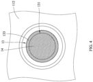
- Fig. 4 illustrates a cross-sectional view of the second pipe 13 of the 3D heat transfer device 10.
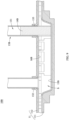
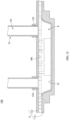
- Fig. 5 illustrates a cross-sectional view of the 3D heat transfer device 10 along the A-A line.
- Fig. 6 illustrates an enlarged view of the cross-section of region Z of Fig. 5 .
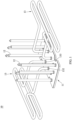
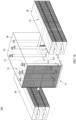
- Fig. 7 illustrates a perspective view with cross-section cut along A-A line of the 3D heat transfer device 10 shown in Fig. 3 .
- the cooling cycle is described hereinafter.
- the cooling fluid within in the liquid-tight chamber S can absorb the heat from a heat source and then vaporizes into a gaseous cooling fluid.
- the vaporized cooling fluid can flow from the liquid-tight chamber S to the hollow space 131 of the second pipe body 13 through the first end 132 along a direction A.
- the vaporized cooling fluid can be condensed back into the liquid form in the second pipe 13.
- the liquified cooling fluid can be propelled by the vaporized cooling fluid from the first end 132 to the second end 133 of the second pipe 13.
- Fig. 9 illustrates a cross-sectional view of the partial enlarged 3D heat transfer device 10B according to one embodiment of the present invention.
- the 3D heat transfer device 10B of the present embodiment is similar to the 3D heat transfer device 10 of the embodiments described above, so the differences between this embodiment and the earlier-mentioned embodiments will be explained below, and the similarities will not be repeated.
- the 3D heat transfer device 10A can include two blocking-flow wick 14B that is each disposed in the second end 133 of the two second pipes bodies.
- the 3D heat transfer device 10B can include a first wick 15B that is disposed in the first shell 111 and a second wick 16B that is disposed in the second shell 112.
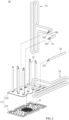
- Fig. 10 illustrates a perspective view of a 3D heat transfer device 10C in accordance with one embodiment of the present invention.
- the 3D heat transfer device 10C of this embodiment is similar to the 3D heat transfer device 10 of the earlier-mentioned embodiments, so the differences between this embodiment and the earlier-mentioned embodiments will be explained below, and the similarities will not be repeated.
- the 3D heat transfer device 10C can include a plurality of fins 18. These fins 18 are respectively surround the first pipes 12 and the second pipes 13. In this way, the heat dissipation area of the 3D heat transfer device 10C can be increased.
- Fig. 11 illustrates a cross-sectional view of the partial enlarged 3D heat transfer device 10D in accordance with one embodiment of the present invention.
- the 3D heat transfer device 10D of this embodiment is similar to the 3D heat transfer device 10 of the earlier-mentioned embodiments, so the differences between this embodiment and the earlier-mentioned embodiments will be explained below, and the similarities will not be repeated.
- a second wick 16D disposed in the second shell body 112 can block the second end 133 of the second pipe 13 and restrict the flow of the cooling fluid.
- the 3D heat transfer device 10D can include two third wicks 19 that each is disposed in the hollow space 131 of the second pipe 13 close to the second end 133.
- the third wick 19 can be hollow and can be disposed on the inner surface of the second pipe 13.
- the third wick 19 use a coarser powder or capillary to provide a greater permeability. That is, the third wick 19 can provide higher capillary transfer velocity. In this way, the liquified cooling fluid can be quickly absorbed into the third wick 19 and returned to the second wick 16D.
- the permeability of the third wick 19 is greater than the permeability of the blocking-flow wick 14 of the earlier-mentioned embodiments.
- the third wick 19 is connected and at the same level as the second wick 16D. That is, the bottom edge of the third wick 19 is connected and at the same level as the outer surface of the second wick 16D.
- Fig. 12 illustrates a cross-sectional view of the partial enlarged 3D heat transfer device 10E in accordance with one embodiment of the present invention.
- the 3D heat transfer device 10E of this embodiment is similar to the 3D heat transfer device 10 of the earlier-mentioned embodiments, so the differences between this embodiment and the earlier-mentioned embodiments will be explained below, and the similarities will not be repeated.
- the 3D heat transfer device 10E can include a second wick 16E disposed in the second shell body 112 of the thermal conductive shell body 12 and completely cover the inner surface of the second shell body 112.
- the second wick 16E also covers the second ends 133 of the second pipes 13.
- the second wick 16E can just cover the second ends 133 of the second pipes 13 to prevent the vaporized cooling fluid flow back to the liquid-tight chamber S.
- the 3D heat transfer devices described in the above embodiments can provide an increase to the heat dissipating area of the device by providing the second pipe bodies having a middle section that is away from the thermal conductive shell.
- the disclosed 3D heat transfer devices according to the above embodiment can have a lower thermal resistance and a higher heat transfer capacity. In this way, the heat dissipation efficiency of the 3D heat transfer device can be improved.
- compositions and methods are described in terms of “comprising,” “containing,” or “including” various components or steps, the compositions and methods can also “consist essentially of' or “consist of” the various components and steps. All numbers and ranges disclosed above may vary by some number. Whenever a numerical range with a lower limit and an upper limit is disclosed, any number and any included range falling within the range is specifically disclosed.
Landscapes
- Engineering & Computer Science (AREA)
- Life Sciences & Earth Sciences (AREA)
- Sustainable Development (AREA)
- Physics & Mathematics (AREA)
- Thermal Sciences (AREA)
- Mechanical Engineering (AREA)
- General Engineering & Computer Science (AREA)
- Cooling Or The Like Of Electrical Apparatus (AREA)
Applications Claiming Priority (1)
| Application Number | Priority Date | Filing Date | Title |
|---|---|---|---|
| CN202311843940.2A CN120232295A (zh) | 2023-12-28 | 2023-12-28 | 立体传热装置 |
Publications (1)
| Publication Number | Publication Date |
|---|---|
| EP4579166A1 true EP4579166A1 (de) | 2025-07-02 |
Family
ID=93794522
Family Applications (1)
| Application Number | Title | Priority Date | Filing Date |
|---|---|---|---|
| EP24217366.4A Pending EP4579166A1 (de) | 2023-12-28 | 2024-12-04 | Dreidimensionale wärmeübertragungsvorrichtung |
Country Status (4)
| Country | Link |
|---|---|
| US (1) | US20250216158A1 (de) |
| EP (1) | EP4579166A1 (de) |
| CN (1) | CN120232295A (de) |
| TW (1) | TW202526250A (de) |
Citations (5)
| Publication number | Priority date | Publication date | Assignee | Title |
|---|---|---|---|---|
| US20170153066A1 (en) * | 2015-12-01 | 2017-06-01 | Asia Vital Components Co., Ltd. | Heat dissipation device |
| US20200370837A1 (en) * | 2019-05-23 | 2020-11-26 | Asia Vital Components (China) Co., Ltd. | Complex vapor chamber structure |
| US20220018609A1 (en) * | 2020-07-20 | 2022-01-20 | Auras Technology Co., Ltd. | Three-dimensional heat dissipating device |
| US20230213288A1 (en) * | 2022-01-06 | 2023-07-06 | Vast Glory Electronics & Hardware & Plastic(Hui Zhou) Ltd. | Three-dimensional heat transfer device |
| US20230358482A1 (en) * | 2020-11-24 | 2023-11-09 | Vast Glory Electronics & Hardware & Plastic(Hui Zhou) Ltd. | Three-dimensional heat exchanger |
-
2023
- 2023-12-28 CN CN202311843940.2A patent/CN120232295A/zh active Pending
-
2024
- 2024-04-29 TW TW113115970A patent/TW202526250A/zh unknown
- 2024-11-13 US US18/945,734 patent/US20250216158A1/en active Pending
- 2024-12-04 EP EP24217366.4A patent/EP4579166A1/de active Pending
Patent Citations (5)
| Publication number | Priority date | Publication date | Assignee | Title |
|---|---|---|---|---|
| US20170153066A1 (en) * | 2015-12-01 | 2017-06-01 | Asia Vital Components Co., Ltd. | Heat dissipation device |
| US20200370837A1 (en) * | 2019-05-23 | 2020-11-26 | Asia Vital Components (China) Co., Ltd. | Complex vapor chamber structure |
| US20220018609A1 (en) * | 2020-07-20 | 2022-01-20 | Auras Technology Co., Ltd. | Three-dimensional heat dissipating device |
| US20230358482A1 (en) * | 2020-11-24 | 2023-11-09 | Vast Glory Electronics & Hardware & Plastic(Hui Zhou) Ltd. | Three-dimensional heat exchanger |
| US20230213288A1 (en) * | 2022-01-06 | 2023-07-06 | Vast Glory Electronics & Hardware & Plastic(Hui Zhou) Ltd. | Three-dimensional heat transfer device |
Also Published As
| Publication number | Publication date |
|---|---|
| CN120232295A (zh) | 2025-07-01 |
| TW202526250A (zh) | 2025-07-01 |
| US20250216158A1 (en) | 2025-07-03 |
Similar Documents
| Publication | Publication Date | Title |
|---|---|---|
| US7543630B2 (en) | Heat pipe incorporating outer and inner pipes | |
| US7013958B2 (en) | Sintered grooved wick with particle web | |
| CN100390488C (zh) | 热传递装置及其制造方法 | |
| CN203672209U (zh) | 一种具有梯度孔隙结构毛细吸液芯的微型毛细泵环 | |
| US20120043060A1 (en) | Loop heat pipe | |
| US20060196640A1 (en) | Vapor chamber with boiling-enhanced multi-wick structure | |
| US20030159809A1 (en) | Capillary evaporator | |
| US20100243214A1 (en) | Flat plate type micro heat transport device | |
| WO2006107492A2 (en) | Capillary condenser/evaporator | |
| JPH088421B2 (ja) | 放熱装置 | |
| WO2004042305A2 (en) | Optimal spreader system, device and method for fluid cooled micro-scaled heat exchange | |
| TWI780786B (zh) | 散熱裝置 | |
| US10240873B2 (en) | Joint assembly of vapor chambers | |
| US7234513B2 (en) | Microchannel flat-plate heat pipe with parallel grooves for recycling coolant | |
| US7120022B2 (en) | Loop thermosyphon with wicking structure and semiconductor die as evaporator | |
| US20050274496A1 (en) | Boiling cooler | |
| EP4579166A1 (de) | Dreidimensionale wärmeübertragungsvorrichtung | |
| KR100659582B1 (ko) | 루프형 마이크로 열이송 장치 | |
| CN110678038A (zh) | 一种散热装置及空调变频模块结构 | |
| TWM524451U (zh) | 整合式散熱裝置 | |
| US20250067519A1 (en) | Three-dimensional heat transfer device | |
| EP4600597A1 (de) | Kühlvorrichtung mit hoher wärmeleistung | |
| TWI600367B (zh) | 整合式散熱裝置 | |
| CN216282948U (zh) | 一种回路热管 | |
| KR102219184B1 (ko) | 3차원 환상형 히트싱크 |
Legal Events
| Date | Code | Title | Description |
|---|---|---|---|
| PUAI | Public reference made under article 153(3) epc to a published international application that has entered the european phase |
Free format text: ORIGINAL CODE: 0009012 |
|
| STAA | Information on the status of an ep patent application or granted ep patent |
Free format text: STATUS: THE APPLICATION HAS BEEN PUBLISHED |
|
| AK | Designated contracting states |
Kind code of ref document: A1 Designated state(s): AL AT BE BG CH CY CZ DE DK EE ES FI FR GB GR HR HU IE IS IT LI LT LU LV MC ME MK MT NL NO PL PT RO RS SE SI SK SM TR |
|
| STAA | Information on the status of an ep patent application or granted ep patent |
Free format text: STATUS: REQUEST FOR EXAMINATION WAS MADE |
|
| 17P | Request for examination filed |
Effective date: 20251119 |