EP4579158A1 - Refrigeration device - Google Patents
Refrigeration device Download PDFInfo
- Publication number
- EP4579158A1 EP4579158A1 EP23856619.4A EP23856619A EP4579158A1 EP 4579158 A1 EP4579158 A1 EP 4579158A1 EP 23856619 A EP23856619 A EP 23856619A EP 4579158 A1 EP4579158 A1 EP 4579158A1
- Authority
- EP
- European Patent Office
- Prior art keywords
- mounting
- door
- lateral
- plate
- main body
- Prior art date
- Legal status (The legal status is an assumption and is not a legal conclusion. Google has not performed a legal analysis and makes no representation as to the accuracy of the status listed.)
- Pending
Links
Images



Classifications
-
- F—MECHANICAL ENGINEERING; LIGHTING; HEATING; WEAPONS; BLASTING
- F25—REFRIGERATION OR COOLING; COMBINED HEATING AND REFRIGERATION SYSTEMS; HEAT PUMP SYSTEMS; MANUFACTURE OR STORAGE OF ICE; LIQUEFACTION SOLIDIFICATION OF GASES
- F25D—REFRIGERATORS; COLD ROOMS; ICE-BOXES; COOLING OR FREEZING APPARATUS NOT OTHERWISE PROVIDED FOR
- F25D23/00—General constructional features
- F25D23/02—Doors; Covers
-
- E—FIXED CONSTRUCTIONS
- E06—DOORS, WINDOWS, SHUTTERS, OR ROLLER BLINDS IN GENERAL; LADDERS
- E06B—FIXED OR MOVABLE CLOSURES FOR OPENINGS IN BUILDINGS, VEHICLES, FENCES OR LIKE ENCLOSURES IN GENERAL, e.g. DOORS, WINDOWS, BLINDS, GATES
- E06B3/00—Window sashes, door leaves, or like elements for closing wall or like openings; Layout of fixed or moving closures, e.g. windows in wall or like openings; Features of rigidly-mounted outer frames relating to the mounting of wing frames
- E06B3/70—Door leaves
- E06B3/7001—Coverings therefor; Door leaves imitating traditional raised panel doors, e.g. engraved or embossed surfaces, with trim strips applied to the surfaces
-
- F—MECHANICAL ENGINEERING; LIGHTING; HEATING; WEAPONS; BLASTING
- F25—REFRIGERATION OR COOLING; COMBINED HEATING AND REFRIGERATION SYSTEMS; HEAT PUMP SYSTEMS; MANUFACTURE OR STORAGE OF ICE; LIQUEFACTION SOLIDIFICATION OF GASES
- F25D—REFRIGERATORS; COLD ROOMS; ICE-BOXES; COOLING OR FREEZING APPARATUS NOT OTHERWISE PROVIDED FOR
- F25D11/00—Self-contained movable devices, e.g. domestic refrigerators
- F25D11/02—Self-contained movable devices, e.g. domestic refrigerators with cooling compartments at different temperatures
-
- F—MECHANICAL ENGINEERING; LIGHTING; HEATING; WEAPONS; BLASTING
- F25—REFRIGERATION OR COOLING; COMBINED HEATING AND REFRIGERATION SYSTEMS; HEAT PUMP SYSTEMS; MANUFACTURE OR STORAGE OF ICE; LIQUEFACTION SOLIDIFICATION OF GASES
- F25D—REFRIGERATORS; COLD ROOMS; ICE-BOXES; COOLING OR FREEZING APPARATUS NOT OTHERWISE PROVIDED FOR
- F25D23/00—General constructional features
- F25D23/02—Doors; Covers
- F25D23/028—Details
-
- A—HUMAN NECESSITIES
- A47—FURNITURE; DOMESTIC ARTICLES OR APPLIANCES; COFFEE MILLS; SPICE MILLS; SUCTION CLEANERS IN GENERAL
- A47B—TABLES; DESKS; OFFICE FURNITURE; CABINETS; DRAWERS; GENERAL DETAILS OF FURNITURE
- A47B96/00—Details of cabinets, racks or shelf units not covered by a single one of groups A47B43/00 - A47B95/00; General details of furniture
- A47B96/20—Furniture panels or like furniture elements
- A47B2096/208—Decorative panels for household appliances
-
- A—HUMAN NECESSITIES
- A47—FURNITURE; DOMESTIC ARTICLES OR APPLIANCES; COFFEE MILLS; SPICE MILLS; SUCTION CLEANERS IN GENERAL
- A47F—SPECIAL FURNITURE, FITTINGS, OR ACCESSORIES FOR SHOPS, STOREHOUSES, BARS, RESTAURANTS OR THE LIKE; PAYING COUNTERS
- A47F3/00—Show cases or show cabinets
- A47F3/04—Show cases or show cabinets air-conditioned, refrigerated
- A47F3/0404—Cases or cabinets of the closed type
- A47F3/0426—Details
- A47F3/043—Doors, covers
-
- E—FIXED CONSTRUCTIONS
- E06—DOORS, WINDOWS, SHUTTERS, OR ROLLER BLINDS IN GENERAL; LADDERS
- E06B—FIXED OR MOVABLE CLOSURES FOR OPENINGS IN BUILDINGS, VEHICLES, FENCES OR LIKE ENCLOSURES IN GENERAL, e.g. DOORS, WINDOWS, BLINDS, GATES
- E06B3/00—Window sashes, door leaves, or like elements for closing wall or like openings; Layout of fixed or moving closures, e.g. windows in wall or like openings; Features of rigidly-mounted outer frames relating to the mounting of wing frames
- E06B3/70—Door leaves
- E06B2003/7011—Door leaves with easily replaceable or interchangeable panels
-
- F—MECHANICAL ENGINEERING; LIGHTING; HEATING; WEAPONS; BLASTING
- F25—REFRIGERATION OR COOLING; COMBINED HEATING AND REFRIGERATION SYSTEMS; HEAT PUMP SYSTEMS; MANUFACTURE OR STORAGE OF ICE; LIQUEFACTION SOLIDIFICATION OF GASES
- F25D—REFRIGERATORS; COLD ROOMS; ICE-BOXES; COOLING OR FREEZING APPARATUS NOT OTHERWISE PROVIDED FOR
- F25D2400/00—General features of, or devices for refrigerators, cold rooms, ice-boxes, or for cooling or freezing apparatus not covered by any other subclass
- F25D2400/18—Aesthetic features
Definitions
- the present application relates to the field of refrigeration technology, particularly to refrigeration appliances.
- the mounting groove has an upper wall and a lower wall oppositely arranged in an up-down direction;
- the mounting member has a bottom plate supported on the lower wall, and positioning protrusions are provided on the lower wall, and positioning slots matching with the positioning protrusions are provided on the bottom plate.
- a refrigeration appliance As shown in FIGS. 1-6 , a refrigeration appliance is disclosed.
- the refrigeration appliance can be a refrigerator, including: a cabinet, a door 1 mounted on the cabinet, and a panel 2 mounted on the front side of the door 1.
- the panel 2 is mounted and fixed on the front side of the door 1 to form a decoration of the door 1.
- the panel 2 can be a stone panel, glass panel, or other decorative panel fixed on the door 1.
- the above structure allows the panel 2 to be separate from the door 1, enabling users to replace and select corresponding panels 2 according to their actual needs, thus meeting users' diverse requirements.
- the panel 2 can also be designed with patterns matching indoor decoration styles, thereby enhancing aesthetics.
- the above structure requires the panel 2 to be conveniently mounted and fixed on the door 1, therefore how to configure the panel 2 for convenient installation, fixing, or removal is an important issue.
- the door 1 also has positioning protrusions 13 provided on the lower walls 12; portions of the lower walls 12 of the mounting grooves 10 located at the front side of the positioning protrusions 13 form overlap portions 14; the planes where the overlap portions 14 are located extend horizontally and the overlap portions 14 are positioned near the openings of the mounting grooves 10.
- the overlap portion 14 is actually a part of the lower wall 12. After the mounting member 3 fixed on the panel 2 aligns with the mounting groove 10, the mounting member 3 can first be supported on the overlap portion 14, then the panel 2 can be pushed horizontally to achieve installation and fixing of the mounting member 3 in the mounting groove 10.
- a plurality of mounting members 3 matching with the mounting grooves 10 are provided on the side of the panel 2 facing the door 1, and positioning slots 30 matching with the positioning protrusions 13 are provided on the mounting members 3.
- the mounting grooves 10 opening toward the front side facilitate the alignment of mounting members 3 on the panel 2 with the mounting grooves 10, thus making it more convenient to position the mounting members 3 in the mounting grooves 10 for installing and fixing the panel 2.
- the mounting members 3 on the panel 2 first align with the positioning slots 30, then the mounting members 3 overlap with the overlap portions 14, and the panel 2 can be installed and fixed on the door 1 by pushing horizontally, which is more convenient than installing and fixing the panel through oblique insertion.
- inclined guide portions enables smoother installation and positioning of the panel 2 in the mounting grooves 30. It can be understood that since the height of the inclined guide portions gradually increases away from the openings of the mounting grooves 30, the panel 2 will relatively move upward or jump up on the inclined guide portions before being fully installed and fixed. Therefore, to prevent the panel 2 from being blocked during upward movement or jumping, the dimension from the top of the mounting member 3 to the upper wall 11 is not less than the distance from the top of the positioning protrusion 13 to the lower wall 12.
- the lateral support portion 32 includes a connecting plate 321 provided on one side of the bottom plate 31 and a transverse support plate 322 provided on the connecting plate 321.
- the connecting plate 321 is configured to abut against the side wall of the lateral limiting portion 15, and the transverse support plate 322 is supported on the top of the lateral limiting portion 15.
- the plane where the transverse support plate 322 is located is different from the plane where the bottom plate 31 is located, with the plane of the transverse support plate 322 being higher than that of the bottom plate 31.
- the plane of the transverse support plate 322 is parallel to the plane of the bottom plate 31, while the connecting plate 321 extends obliquely relative to the horizontal plane.
- the mounting member 3 disclosed in this embodiment enables the panel 2 to be stably supported in the mounting groove 10 and limits the mounting member 3 in the left-right direction, thereby avoiding wobbling of the mounting member 3 and providing higher stability after installation.
- arcuate transition portions are provided between the bottom plate 31 and the connecting plate 321, and between the connecting plate 321 and the transverse support plate 322.
- the arcuate transition portions make the transitions between the connecting plate 321 and bottom plate 31, and between the transverse support plate 322 and connecting plate 321 smoother, enabling smoother pushing of the mounting member 3 into the mounting groove 10.
- the decorative strip-mounting member 41 is provided with an upper positioning portion 411 that cooperates with the upper positioning slot 1101 to limit the decorative strip 4 in the front-back direction, and a lower positioning portion 412 that cooperates with the lower positioning slot 1102 to limit the decorative strip 4 in the left-right direction.
- the lower positioning portion 412 includes elastic snap feet with hook-shaped portions that are positioned in the lower positioning slot 1104 and abut against the second limiting protrusion 1104.
- the decorative strip 4 also has elastic engagement members 43 provided on the decorative plate 42, and positioning holes matching with the elastic engagement members 43 are provided on the door main body 100.
- the elastic engagement member 43 includes an engagement main body 431 positioned on the decorative plate 42 and multiple elastic snap feet 432 provided on the engagement main body 431.
- the multiple elastic snap feet 432 are arranged in a ring shape on the engagement main body 431 and have a first state where they converge toward each other and accumulate resilient force. In the first state, the elastic snap feet 432 converge together to allow the elastic engagement member 43 to pass through the positioning hole. After passing through the positioning hole, the accumulated resilient force drives the elastic snap feet 432 to expand and press against the side walls of the positioning hole, thereby positioning the elastic engagement member 43 in the positioning hole and achieving installation and fixing of the elastic engagement member 43 on the door 1.
- the parallel arrangement of the front cover plate 45 and mounting-fixing plate 33 together covers the mounting groove 10, effectively concealing it. After covering the mounting groove 10, they effectively compensate for the reduction in door thickness caused by the mounting groove 10, thereby reducing the impact on refrigerator insulation caused by the mounting groove 10.
- the panel 2 is positioned on the front side of the front cover plate 45 and completely covers the front cover plate 45 in the front direction. Covering the front cover plate 45 with panel 2 avoids exposing the decorative plate 4 in the front direction, making the refrigerator more aesthetically pleasing from the front view.
- the panel 2 also has upper connecting plates 5 oppositely arranged in the up-down direction on the side facing the door.
- the upper connecting plate 5 has connecting plate positioning holes that open in a direction away from the panel 2; the connecting plate positioning holes match with the bolts 1003.
- a pair of nuts 1002 are provided on the bolt 1003, and the upper connecting plate 5 is clamped and fixed by the pair of nuts 1002. Using a pair of nuts 1002 to clamp and fix the upper connecting plate 5 also makes it more convenient to adjust the position of the upper connecting plate 5.
Landscapes
- Engineering & Computer Science (AREA)
- Chemical & Material Sciences (AREA)
- Combustion & Propulsion (AREA)
- Physics & Mathematics (AREA)
- Mechanical Engineering (AREA)
- Thermal Sciences (AREA)
- General Engineering & Computer Science (AREA)
- Civil Engineering (AREA)
- Structural Engineering (AREA)
- Refrigerator Housings (AREA)
- Devices That Are Associated With Refrigeration Equipment (AREA)
Abstract
Description
- The present application relates to the field of refrigeration technology, particularly to refrigeration appliances.
- Refrigerator appliance is a widely used household appliance. With the improvement of people's living standards, users have higher requirements for the appearance of refrigerators. In the prior art, to ensure the aesthetics and diversity of refrigerator door panels, the panel and the door are typically designed as separate components, with the panel being mounted on the door.
- In the existing structural designs, the panel is not only difficult to install, but the fasteners are also easily exposed on the panel after installation, affecting the aesthetic appearance.
- The object of the present application is to provide a refrigeration appliance to address the deficiencies in the prior art, which enables the lateral mounting plate positioned in the mounting groove to be more conveniently operated when being fixed to the side wall, and since the panel is mounted on the side wall of the mounting groove through the lateral mounting plate, the panel can cover the fasteners from the front side after installation, thereby improving the aesthetic appearance of the front side of the refrigeration appliance.
- The present application provides a refrigeration appliance, comprising: a cabinet, a door mounted on the cabinet, and a panel mounted on a front side of the door;
- wherein a plurality of mounting grooves are provided on the door and open toward the panel, and a lateral opening is provided on a side of the door to expose the mounting grooves; the mounting groove has a side wall opposite to the lateral opening;
- wherein a plurality of mounting members are provided on a side of the panel facing the door, the mounting members are positioned in the mounting grooves and have lateral mounting plates opposite to the side walls, and the lateral mounting plates are fixed to the side walls.
- Furthermore, wherein door-mounting holes are provided on the side walls, mounting plate-mounting holes matching with the door-mounting holes are provided on the lateral mounting plates; the mounting plate-mounting holes are opposite to the lateral openings; the lateral mounting plates are fixed to the side walls by fasteners, and the fasteners are simultaneously positioned in the door-mounting holes and the mounting plate-mounting holes.
- Furthermore, wherein the mounting groove has an upper wall and a lower wall oppositely arranged in an up-down direction; the mounting member has a bottom plate supported on the lower wall, and positioning protrusions are provided on the lower wall, and positioning slots matching with the positioning protrusions are provided on the bottom plate.
- Furthermore, wherein a portion of the lower wall of the mounting groove located at a front side of the positioning protrusion forms an overlap portion, and a plane where the overlap portion is located extends horizontally.
- Furthermore, wherein the positioning protrusion has an inclined guide portion inclined toward an opening direction of the mounting groove, and a height of the inclined guide portion gradually increases away from the opening of the mounting groove.
- Furthermore, wherein a dimension from a top of the lateral mounting plate to the upper wall is not less than a distance from a top of the positioning protrusion to the lower wall.
- Furthermore, wherein the mounting member further has lateral support portions provided on opposite sides of the bottom plate, and a pair of lateral limiting portions are provided in the mounting groove to be opposite to the lateral support portions and limit the lateral support portions in a left-right direction;
- wherein the lateral support portion includes a connecting plate provided on one side of the bottom plate and a transverse support plate provided on the connecting plate, the connecting plate is configured to abut against a side wall of the lateral limiting portion, and the transverse support plate is supported on a top of the lateral limiting portion;
- wherein the connecting plate is fixedly connected with the lateral mounting plate;
- wherein arcuate transition portions are provided between the bottom plate and the connecting plate, and between the connecting plate and the transverse support plate;
- wherein the bottom plate, the connecting plate and the transverse support plate are integrally formed.
- Furthermore, wherein the door includes a door main body and upper and lower beams provided on top and bottom of the door main body; bolts extending in an up-down direction are provided on both the upper beam and the lower beam;
- wherein the panel further has upper and lower connecting plates oppositely arranged in the up-down direction on a side facing the door, both the upper and lower connecting plates have connecting plate positioning holes; the connecting plate positioning holes match with the bolts;
- wherein a pair of nuts are provided on the bolt, and the connecting plate is clamped and fixed by the pair of nuts.
- Furthermore, wherein the door includes a door main body and a door-mounting member provided on the door main body, the mounting grooves are provided on the door-mounting member, and the door-mounting member is integrally injection molded;
- wherein the lateral opening is provided on the door-mounting member, and the refrigeration appliance further has decorative strips provided on left and right sides of the door main body, decorative strip-mounting members are provided on a side of the decorative strips facing the door main body, the decorative strip-mounting members are opposite to the lateral openings and positioned on the door-mounting member;
- wherein decorative strip positioning slots are provided on the decorative strip-mounting members at positions of the lateral openings, opening directions of the decorative strip positioning slots are perpendicular to opening directions of the mounting grooves, and the decorative strip positioning slots are exposed toward the mounting grooves; the decorative strip-mounting members have elastic snap feet engaged in the decorative strip positioning slots.
- Furthermore, wherein the decorative strips further have elastic engagement members on a side facing the door main body, positioning holes matching with the elastic engagement members are provided on the door main body, the elastic engagement member includes an engagement main body positioned on the decorative strip and a plurality of elastic snap feet provided on the engagement main body, the plurality of elastic snap feet are arranged in a ring shape on the engagement main body and have a first state where they converge toward each other and accumulate resilient force.
- Compared with the prior art, the present application provides mounting grooves that open toward the front side on the door and lateral openings toward the door sides, which enables the lateral mounting plate positioned in the mounting groove to be more conveniently operated when being fixed to the side wall, and since the panel is mounted on the side wall of the mounting groove through the lateral mounting plate, the panel can cover the fasteners from the front side after installation, thereby improving the aesthetic appearance of the front side of the refrigeration appliance.
-
-
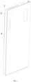
FIG. 1 is a structural diagram of the refrigeration appliance according to an embodiment of the present application; -
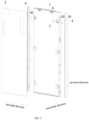
FIG. 2 is an exploded view of the refrigeration appliance according to an embodiment of the present application; -
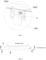
FIG. 3 is an enlarged view of area A inFIG. 2 ; -
FIG. 4 is a top view of the refrigeration appliance according to an embodiment of the present application; -
FIG. 5 is a sectional view along direction CC inFIG. 4 ; -
FIG. 6 is an enlarged view of area B inFIG. 5 ; -
FIG. 7 is a structural diagram of the refrigeration appliance with the panel removed according to an embodiment of the present application; -
FIG. 8 is a structural diagram of the panel of the refrigeration appliance according to an embodiment of the present application; -
FIG. 9 is a first structural diagram of the door-mounting member of the refrigeration appliance according to an embodiment of the present application; -
FIG. 10 is a front view of the door-mounting member of the refrigeration appliance according to an embodiment of the present application; -
FIG. 11 is a first structural diagram of the mounting member of the refrigeration appliance according to an embodiment of the present application; -
FIG. 12 is a second structural diagram of the mounting member of the refrigeration appliance according to an embodiment of the present application; -
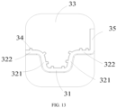
FIG. 13 is a front view of the mounting member of the refrigeration appliance according to an embodiment of the present application; -
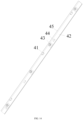
FIG. 14 is a structural diagram of the decorative strip of the refrigeration appliance according to an embodiment of the present application; -
FIG. 15 is a structural diagram of the elastic engagement member of the refrigeration appliance according to an embodiment of the present application; -
FIG. 16 is a structural diagram of the decorative strip-mounting member of the refrigeration appliance according to an embodiment of the present application. - Reference Numerals: 1-door, 10-mounting groove, 11-upper wall, 12-lower wall, 13-positioning protrusion, 14-overlap portion, 15-lateral limiting portion, 16-lateral opening, 17-side wall, 170-door-mounting hole, 2-panel, 3-mounting member, 30-positioning slot, 31-bottom plate, 32-lateral support portion, 321-connecting plate, 322-transverse support plate, 33-mounting-fixing plate, 34-reinforcing rib, 35-lateral mounting plate, 350-mounting plate-mounting hole, 4-decorative strip, 41-decorative strip-mounting member, 411-upper positioning portion, 412-lower positioning portion, 42-decorative plate, 43-elastic engagement member, 431-engagement main body, 432-elastic snap foot, 44-magnetic member, 45-front cover plate, 5-upper connecting plate, 100-door main body, 1001-upper beam, 1002-nut, 1003-bolt, 110-door-mounting member, 1101-upper positioning slot, 1102-lower positioning slot, 1103-first limiting protrusion, 1104-second limiting protrusion.
- In the description of this utility model, it should be understood that terms such as "center", "longitudinal", "transverse", "up", "down", "front", "rear", "left", "right", "vertical", "horizontal", "top", "bottom", "inner", "outer" indicating directional or positional relationships are based on the directional or positional relationships shown in the drawings, are merely for the convenience of describing this utility model and simplifying the description, and do not indicate or imply that the referred device or element must have a specific orientation, be constructed in a specific orientation, or operate in a specific orientation, therefore should not be construed as limitations of this utility model.
- Furthermore, terms "first" and "second" are used only for descriptive purposes and should not be understood as indicating or implying relative importance.
- In the description of this utility model, it should be noted that unless otherwise explicitly specified and limited, terms such as "mounted", "position", "connected" should be broadly understood. For example, they can refer to fixed connection, integral connection, or detachable connection; mechanical connection or electrical connection, or internal communication between two elements; direct connection or indirect connection through intermediate media. Those skilled in the art can understand the specific meanings of these terms based on specific circumstances.
- The embodiments described below with reference to the drawings are exemplary and are only used to explain the present application, and should not be construed as limitations of the present application.
- Embodiments of the present application: As shown in
FIGS. 1-6 , a refrigeration appliance is disclosed. The refrigeration appliance can be a refrigerator, including: a cabinet, adoor 1 mounted on the cabinet, and apanel 2 mounted on the front side of thedoor 1. Thepanel 2 is mounted and fixed on the front side of thedoor 1 to form a decoration of thedoor 1. In specific embodiments, thepanel 2 can be a stone panel, glass panel, or other decorative panel fixed on thedoor 1. The above structure allows thepanel 2 to be separate from thedoor 1, enabling users to replace and selectcorresponding panels 2 according to their actual needs, thus meeting users' diverse requirements. Thepanel 2 can also be designed with patterns matching indoor decoration styles, thereby enhancing aesthetics. - The above structure requires the
panel 2 to be conveniently mounted and fixed on thedoor 1, therefore how to configure thepanel 2 for convenient installation, fixing, or removal is an important issue. - In this embodiment of the refrigeration appliance, which has a
door 1 and apanel 2 mounted on thedoor 1, a plurality ofmounting grooves 10 are provided on thedoor 1 opening toward the front side. It can be understood that since thepanel 2 is mounted on the front side of thedoor 1, themounting grooves 10 also open toward thepanel 2, and themounting grooves 10 haveupper walls 11 andlower walls 12 oppositely arranged in the up-down direction. - The
door 1 also has positioningprotrusions 13 provided on thelower walls 12; portions of thelower walls 12 of themounting grooves 10 located at the front side of thepositioning protrusions 13form overlap portions 14; the planes where theoverlap portions 14 are located extend horizontally and theoverlap portions 14 are positioned near the openings of themounting grooves 10. Theoverlap portion 14 is actually a part of thelower wall 12. After the mountingmember 3 fixed on thepanel 2 aligns with the mountinggroove 10, the mountingmember 3 can first be supported on theoverlap portion 14, then thepanel 2 can be pushed horizontally to achieve installation and fixing of the mountingmember 3 in the mountinggroove 10. - A plurality of mounting
members 3 matching with the mountinggrooves 10 are provided on the side of thepanel 2 facing thedoor 1, andpositioning slots 30 matching with the positioningprotrusions 13 are provided on the mountingmembers 3. - In this embodiment, the mounting
grooves 10 opening toward the front side facilitate the alignment of mountingmembers 3 on thepanel 2 with the mountinggrooves 10, thus making it more convenient to position the mountingmembers 3 in the mountinggrooves 10 for installing and fixing thepanel 2. With theoverlap portions 14 extending horizontally provided near the openings on thelower walls 12 of the mountinggrooves 10, during installation, the mountingmembers 3 on thepanel 2 first align with thepositioning slots 30, then the mountingmembers 3 overlap with theoverlap portions 14, and thepanel 2 can be installed and fixed on thedoor 1 by pushing horizontally, which is more convenient than installing and fixing the panel through oblique insertion. - In this embodiment, positioning
protrusions 13 are also provided, which work withpositioning slots 30 on the mountingmembers 3 to achieve installation and fixing of the mountingmembers 3 in thepositioning slots 30. Since thepositioning protrusions 13 affect the horizontal pushing installation of thepanel 2, to reduce this impact, the positioningprotrusions 13 in this embodiment have inclined guide portions that are inclined toward the opening direction of the mountinggrooves 30, and the height of the inclined guide portions gradually increases away from the openings of the mountinggrooves 30. - The provision of inclined guide portions enables smoother installation and positioning of the
panel 2 in the mountinggrooves 30. It can be understood that since the height of the inclined guide portions gradually increases away from the openings of the mountinggrooves 30, thepanel 2 will relatively move upward or jump up on the inclined guide portions before being fully installed and fixed. Therefore, to prevent thepanel 2 from being blocked during upward movement or jumping, the dimension from the top of the mountingmember 3 to theupper wall 11 is not less than the distance from the top of thepositioning protrusion 13 to thelower wall 12. - As shown in
FIGS. 9-13 , in this embodiment, the mountingmember 3 has abottom plate 31 opposite to thelower wall 12 andlateral support portions 32 provided on opposite sides of thebottom plate 31. Thepositioning slot 30 is provided on thebottom plate 31, and a pair oflateral limiting portions 15 are provided in the mountinggroove 10 opposite to thelateral support portions 32 to limit thelateral support portions 32 in the left-right direction. The provision oflateral limiting portions 15 enables better positioning of thepanel 2 in the left-right direction. - The
lateral support portion 32 includes a connectingplate 321 provided on one side of thebottom plate 31 and atransverse support plate 322 provided on the connectingplate 321. The connectingplate 321 is configured to abut against the side wall of thelateral limiting portion 15, and thetransverse support plate 322 is supported on the top of thelateral limiting portion 15. The plane where thetransverse support plate 322 is located is different from the plane where thebottom plate 31 is located, with the plane of thetransverse support plate 322 being higher than that of thebottom plate 31. The plane of thetransverse support plate 322 is parallel to the plane of thebottom plate 31, while the connectingplate 321 extends obliquely relative to the horizontal plane. - In this embodiment, a pair of
lateral support portions 32 are symmetrically provided on opposite sides of thebottom plate 31. This structure allows both thelower wall 12 and thelateral limiting portions 15 to support the mountingmember 3, increasing the supporting areas. Specifically, the supporting areas for the mountingmember 3 include thebottom plate 31 and thetransverse support plates 322 provided on both sides of thebottom plate 31, with thebottom plate 31 andtransverse support plates 322 being on different horizontal planes. This structure not only increases the supporting area but also provides better support effect. Since thebottom plate 31 andtransverse support plates 322 are on different horizontal planes, they also provide some support and limitation to thepanel 2 in the up-down direction, preventing thepanel 2 from front-back rotation. - The mounting
member 3 disclosed in this embodiment enables thepanel 2 to be stably supported in the mountinggroove 10 and limits the mountingmember 3 in the left-right direction, thereby avoiding wobbling of the mountingmember 3 and providing higher stability after installation. - As shown in
FIGS. 11-13 , arcuate transition portions are provided between thebottom plate 31 and the connectingplate 321, and between the connectingplate 321 and thetransverse support plate 322. The arcuate transition portions make the transitions between the connectingplate 321 andbottom plate 31, and between thetransverse support plate 322 and connectingplate 321 smoother, enabling smoother pushing of the mountingmember 3 into the mountinggroove 10. - In this embodiment, the
bottom plate 31, connectingplate 321, andtransverse support plate 322 are integrally formed. The mountingmember 3 can be a plastic part, with thebottom plate 31, connectingplate 321, andtransverse support plate 322 being integrally injection molded. The integral formation enhances the strength of the entire mountingmember 3, thereby providing better support for thepanel 2. - Furthermore, to better achieve installation and fixing of the mounting
member 3 on thepanel 2, the mountingmember 3 also has a mounting-fixingplate 33 fixed on thepanel 2. The mounting-fixingplate 33 is fixedly attached to thepanel 2, and thebottom plate 31 andlateral support portions 32 are all provided on the side of the mounting-fixingplate 33 away from thepanel 2. - Furthermore, as shown in
FIGS. 11-13 , to enhance the supporting strength of the mountingmember 3, several reinforcingribs 34 extending in the front-back direction are provided on the side of the mountingmember 3 away from thelower wall 12. Multiple reinforcingribs 34 are provided, arranged parallel to and spaced from each other on the mountingmember 3. In another embodiment, the reinforcingribs 34 can also be divided into two parallel groups intersecting obliquely to form a grid structure. - As shown in
FIGS. 5-10 , in this embodiment, thedoor 1 includes a doormain body 100 and several door-mountingmembers 110 provided on the doormain body 100. The mountinggrooves 10 are provided on the door-mountingmembers 110, which are integrally injection molded, and the mountinggrooves 10 are formed during the molding process of the door-mountingmembers 110. - The door
main body 100 includes an outer shell and an inner liner provided on the outer shell, with a foam layer formed between the inner liner and outer shell. Mounting holes matching with the door-mountingmembers 110 are provided on the outer shell, and the door-mountingmembers 110 are pressed against the outer shell during the formation of the foam layer. - As shown in
FIG. 7 , multiple door-mountingmembers 110 are provided on onedoor 1, divided into two groups and arranged on both sides of the doormain body 100, and the door-mountingmembers 110 are positioned at the left and right edges of the doormain body 110, with the door-mountingmembers 110 exposed from the side of the doormain body 110. - In the above embodiment, the mounting
member 3 is installed and fixed in the mountinggroove 10 only through the engagement between the positioningprotrusion 13 and thepositioning slot 30 on thebottom plate 31. As shown inFIGS. 5-10 , to better achieve the installation and fixing of the mountingmember 3 in the mountinggroove 10, thedoor 1 haslateral openings 16 exposing the mountinggrooves 10 on its sides; the mountinggroove 10 hasside walls 17 opposite to the positions of thelateral openings 16. Specifically, thelateral openings 16 are provided on the door-mountingmembers 110, and theside walls 17 are positioned opposite to thelateral openings 16 in the left-right direction and on opposite sides of the mountinggroove 10. - As shown in
FIGS. 11-13 , the mountingmember 3 also haslateral mounting plates 35 positioned opposite to theside walls 17, and thelateral mounting plates 35 are fixed to theside walls 17. Thelateral mounting plates 35 are fixed to thetransverse support plates 322 and integrally formed with thetransverse support plates 322, with the planes of thelateral mounting plates 35 extending in the up-down direction. - Door-mounting
holes 170 are provided on theside walls 17, and mounting plate-mountingholes 350 matching with the door-mountingholes 170 are provided on thelateral mounting plates 35; the mounting plate-mountingholes 350 are positioned opposite to thepanel lateral openings 16; the mounting plate holes 350 are exposed to the outside through thelateral openings 16, and thelateral mounting plates 35 are fixed to theside walls 17 by fasteners, with the fasteners simultaneously positioned in both the door-mountingholes 170 and the mounting plate-mountingholes 350. - In this embodiment, the door-mounting
holes 170 are threaded holes, and the fasteners include bolts threaded into the threaded holes and nuts provided on the bolts. The nuts press against thelateral mounting plates 35 and clamp thelateral mounting plates 35 firmly to theside walls 17. - In this embodiment, providing
lateral openings 16 on the door-mountingmembers 110 makes it more convenient to operate the fasteners for installation and fixing on thedoor 1. Thelateral openings 16 expose the door-mountingholes 170 from the side direction of the door, making it convenient to install and fix the fasteners in the door-mountingholes 170. - Fixing the
lateral mounting plates 35 to theside walls 17 with fasteners avoids exposure of mounting components on the front side. After installing and fixing thelateral mounting plates 35 with fasteners, the fasteners are covered by thepanel 2, so only the panel is visible from the front direction, improving aesthetics compared to existing solutions where fasteners are exposed on the front side of thepanel 2. - As shown in
FIG. 2 , the refrigeration appliance also hasdecorative strips 4 provided on both left and right sides of thedoor 1. Decorative strip-mountingmembers 41 are provided on the side of thedecorative strips 4 facing the doormain body 100. The decorative strip-mountingmembers 41 are positioned opposite to thelateral openings 16 and positioned at thelateral openings 16. Specifically, the decorative strip-mountingmembers 41 are positioned on the door-mountingmembers 110. - Installing and fixing the
decorative strips 4 on the side of thedoor 1 through decorative strip-mountingmembers 41, while utilizing thelateral openings 16, reduces the number of openings on thedoor 1. Since thelateral openings 16 are integrally formed during the molding of the door-mountingmembers 110, they are easier to manufacture, simplifying the process while facilitating the assembly ofdecorative strips 4. Additionally, the decorative strip-mountingmembers 41 can provide some coverage for thelateral openings 16, and while covering the lateral openings, they can also compensate for the reduction in door thickness caused by the mountinggrooves 10, thereby reducing the decline in thermal insulation performance caused by the reduced door thickness. - In this embodiment, the decorative strip-mounting
members 41 are engaged with the door-mountingmembers 110. Using an engagement method makes it convenient to replace and disassemble thedecorative strips 4, allowing for replacement according to user requirements. - The door-mounting
member 110 hasupper positioning slots 1101 andlower positioning slots 1102 provided on the upper and lower sides of thelateral opening 16 respectively. - As shown in
FIGS. 5-7 , the decorative strip-mountingmember 41 is provided with anupper positioning portion 411 that cooperates with theupper positioning slot 1101 to limit thedecorative strip 4 in the front-back direction, and alower positioning portion 412 that cooperates with thelower positioning slot 1102 to limit thedecorative strip 4 in the left-right direction. - First limiting
protrusions 1103 and second limitingprotrusions 1104 are provided on the door-mountingmember 110 at the position of the lateral opening, arranged opposite to each other in the left-right direction. Thelower positioning slot 1102 is formed between the first limitingprotrusion 1103 and second limiting protrusion, and thelower positioning slot 1102 is exposed toward the mountinggroove 10. - The
lower positioning portion 412 includes elastic snap feet with hook-shaped portions that are positioned in thelower positioning slot 1104 and abut against the second limitingprotrusion 1104. - The
upper positioning slot 1101 opens toward thedecorative strip 4 and is exposed toward the mountinggroove 110. Theupper positioning portion 411 matches with theupper positioning slot 1101 and can be snap-fitted into theupper positioning slot 1101. - The
decorative strip 4 has adecorative plate 42 covering the side of thedoor 1, and the decorative strip-mountingmember 41 is integrally formed on thedecorative plate 42. Thedecorative strip 4 can be made of plastic or aluminum alloy. Making thedecorative strip 4 from plastic or aluminum alloy and integrally forming the decorative strip-mountingmember 41 on thedecorative plate 42 ensures more stable installation of thedecorative strip 4 on thedoor 1, avoiding large gaps between thedecorative strip 4 and thedoor 1 when laterally engaged. - The
decorative strip 4 also haselastic engagement members 43 provided on thedecorative plate 42, and positioning holes matching with theelastic engagement members 43 are provided on the doormain body 100. - As shown in
FIG. 15 , theelastic engagement member 43 includes an engagementmain body 431 positioned on thedecorative plate 42 and multipleelastic snap feet 432 provided on the engagementmain body 431. The multipleelastic snap feet 432 are arranged in a ring shape on the engagementmain body 431 and have a first state where they converge toward each other and accumulate resilient force. In the first state, theelastic snap feet 432 converge together to allow theelastic engagement member 43 to pass through the positioning hole. After passing through the positioning hole, the accumulated resilient force drives theelastic snap feet 432 to expand and press against the side walls of the positioning hole, thereby positioning theelastic engagement member 43 in the positioning hole and achieving installation and fixing of theelastic engagement member 43 on thedoor 1. - Installing and fixing the
decorative strip 4 throughelastic engagement members 43 makes it more convenient to install and remove thedecorative strip 4, facilitating replacement. To better achieve installation and fixing of thedecorative strip 4, theelastic engagement member 43 and the decorative strip-mountingmember 41 are staggered in the front-back direction. - Being staggered in the front-back direction provides two mounting positions for fixing the
decorative strip 4 on thedoor 1, enabling more stable support and fixing of thedecorative strip 4 on thedoor 1. - Furthermore, as shown in
FIG. 14 ,magnetic members 44 are also provided on the side of thedecorative strip 4 facing thedoor 1, and magnetic attraction grooves matching with themagnetic members 44 are provided on thedoor 1. - Since the outer shell of the
door 1 is typically made of iron material, providingmagnetic members 44 on thedecorative strip 4 to magnetically attach to thedoor 1 facilitates easy installation and fixing of thedecorative strip 4 on thedoor 1. - It can be understood that in specific embodiments, the
magnetic members 44 andelastic engagement members 43 do not need to be used simultaneously. They can be used independently, each working with the decorative strip-mountingmember 41 separately, or they can be used together to enhance the installation stability of thedecorative strip 4. - As shown in
FIGS. 7 and14 , thedecorative strip 4 has adecorative plate 42 provided on the side of thedoor 1 and afront cover plate 45 perpendicular to thedecorative plate 42. Thefront cover plate 45 is located at the front side of thedoor 1 and is arranged parallel to the mounting-fixingplate 33. - The parallel arrangement of the
front cover plate 45 and mounting-fixingplate 33 together covers the mountinggroove 10, effectively concealing it. After covering the mountinggroove 10, they effectively compensate for the reduction in door thickness caused by the mountinggroove 10, thereby reducing the impact on refrigerator insulation caused by the mountinggroove 10. - The
panel 2 is positioned on the front side of thefront cover plate 45 and completely covers thefront cover plate 45 in the front direction. Covering thefront cover plate 45 withpanel 2 avoids exposing thedecorative plate 4 in the front direction, making the refrigerator more aesthetically pleasing from the front view. - As shown in
FIGS. 2-5 , to achieve more stable installation and fixing of thepanel 2, thedoor 1 also has anupper beam 1001 provided at the top and bottom of the doormain body 100; theupper beam 1001 is provided withbolts 1003 extending in the up-down direction. - The
panel 2 also has upper connectingplates 5 oppositely arranged in the up-down direction on the side facing the door. The upper connectingplate 5 has connecting plate positioning holes that open in a direction away from thepanel 2; the connecting plate positioning holes match with thebolts 1003. - A pair of nuts 1002 are provided on the
bolt 1003, and the upper connectingplate 5 is clamped and fixed by the pair of nuts 1002. Using a pair of nuts 1002 to clamp and fix the upper connectingplate 5 also makes it more convenient to adjust the position of the upper connectingplate 5. - The above detailed description of the construction, features, and effects of the present application is based on the embodiments shown in the drawings. The above description is only preferred embodiments of the present application. However, the scope of implementation is not limited to what is shown in the drawings. Any changes made according to the concept of this application, or modifications made as equivalent implementations, as long as they do not exceed the spirit covered by the specification and drawings, should all be within the protection scope of this application.
Claims (10)
- A refrigeration appliance, comprising: a cabinet, a door mounted on the cabinet, and a panel mounted on a front side of the door;wherein a plurality of mounting grooves are provided on the door and open toward the panel, and a lateral opening is provided on a side of the door to expose the mounting grooves; the mounting groove has a side wall opposite to the lateral opening;wherein a plurality of mounting members are provided on a side of the panel facing the door, the mounting members are positioned in the mounting grooves and have lateral mounting plates opposite to the side walls, and the lateral mounting plates are fixed to the side walls.
- The refrigeration appliance according to claim 1, wherein door-mounting holes are provided on the side walls, mounting plate-mounting holes matching with the door-mounting holes are provided on the lateral mounting plates; the mounting plate-mounting holes are opposite to the lateral openings; the lateral mounting plates are fixed to the side walls by fasteners, and the fasteners are simultaneously positioned in the door-mounting holes and the mounting plate-mounting holes.
- The refrigeration appliance according to claim 1, wherein the mounting groove has an upper wall and a lower wall oppositely arranged in an up-down direction; the mounting member has a bottom plate supported on the lower wall, and positioning protrusions are provided on the lower wall, and positioning slots matching with the positioning protrusions are provided on the bottom plate.
- The refrigeration appliance according to claim 3, wherein a portion of the lower wall of the mounting groove located at a front side of the positioning protrusion forms an overlap portion, and a plane where the overlap portion is located extends horizontally.
- The refrigeration appliance according to claim 3, wherein the positioning protrusion has an inclined guide portion inclined toward an opening direction of the mounting groove, and a height of the inclined guide portion gradually increases away from the opening of the mounting groove.
- The refrigeration appliance according to claim 3, wherein a dimension from a top of the lateral mounting plate to the upper wall is not less than a distance from a top of the positioning protrusion to the lower wall.
- The refrigeration appliance according to claim 3, wherein the mounting member further has lateral support portions provided on opposite sides of the bottom plate, and a pair of lateral limiting portions are provided in the mounting groove to be opposite to the lateral support portions and limit the lateral support portions in a left-right direction;wherein the lateral support portion includes a connecting plate provided on one side of the bottom plate and a transverse support plate provided on the connecting plate, the connecting plate is configured to abut against a side wall of the lateral limiting portion, and the transverse support plate is supported on a top of the lateral limiting portion;wherein the connecting plate is fixedly connected with the lateral mounting plate;wherein arcuate transition portions are provided between the bottom plate and the connecting plate, and between the connecting plate and the transverse support plate;wherein the bottom plate, the connecting plate and the transverse support plate are integrally formed.
- The refrigeration appliance according to claim 1, wherein the door includes a door main body, an upper beam and lower beam, the upper beam is provided on top of the door main body, and the lower beam is provided on bottom of the door main body; bolts extending in an up-down direction are provided on both the upper beam and the lower beam;wherein the panel further has an upper and a lower connecting plate oppositely arranged in the up-down direction on a side facing the door, both the upper connecting plate and the lower connecting plate have connecting plate positioning holes; the connecting plate positioning holes match with the bolts;wherein a pair of nuts are provided on the bolt, and the connecting plate is clamped and fixed by the pair of nuts.
- The refrigeration appliance according to claim 1, wherein the door includes a door main body and a door-mounting member provided on the door main body, the mounting grooves are provided on the door-mounting member, and the door-mounting member is integrally injection molded;wherein the lateral opening is provided on the door-mounting member, and the refrigeration appliance further has decorative strips provided on left and right sides of the door main body, decorative strip-mounting members are provided on a side of the decorative strips facing the door main body, the decorative strip-mounting members are opposite to the lateral openings and positioned on the door-mounting member;wherein decorative strip positioning slots are provided on the decorative strip-mounting members at positions of the lateral openings, opening directions of the decorative strip positioning slots are perpendicular to opening directions of the mounting grooves, and the decorative strip positioning slots are exposed toward the mounting grooves; the decorative strip-mounting members have elastic snap feet engaged in the decorative strip positioning slots.
- The refrigeration appliance according to claim 9, wherein the decorative strips further have elastic engagement members on a side facing the door main body, positioning holes matching with the elastic engagement members are provided on the door main body, the elastic engagement member includes an engagement main body positioned on the decorative strip and a plurality of elastic snap feet provided on the engagement main body, the plurality of elastic snap feet are arranged in a ring shape on the engagement main body and have a first state where they converge toward each other and accumulate resilient force.
Applications Claiming Priority (2)
| Application Number | Priority Date | Filing Date | Title |
|---|---|---|---|
| CN202211021212.9A CN117663639A (en) | 2022-08-24 | 2022-08-24 | Refrigeration equipment |
| PCT/CN2023/114236 WO2024041529A1 (en) | 2022-08-24 | 2023-08-22 | Refrigeration device |
Publications (2)
| Publication Number | Publication Date |
|---|---|
| EP4579158A1 true EP4579158A1 (en) | 2025-07-02 |
| EP4579158A4 EP4579158A4 (en) | 2025-12-17 |
Family
ID=90012525
Family Applications (1)
| Application Number | Title | Priority Date | Filing Date |
|---|---|---|---|
| EP23856619.4A Pending EP4579158A4 (en) | 2022-08-24 | 2023-08-22 | REFRIGERATION |
Country Status (4)
| Country | Link |
|---|---|
| EP (1) | EP4579158A4 (en) |
| KR (1) | KR20250044900A (en) |
| CN (1) | CN117663639A (en) |
| WO (1) | WO2024041529A1 (en) |
Family Cites Families (10)
| Publication number | Priority date | Publication date | Assignee | Title |
|---|---|---|---|---|
| DE4334761A1 (en) * | 1993-10-12 | 1995-04-13 | Bosch Siemens Hausgeraete | Household appliance for installation in a furniture niche in a kitchenette or the like |
| KR20090115647A (en) * | 2008-11-05 | 2009-11-05 | 신국수 | Side frame for refrigerator door |
| KR102312667B1 (en) * | 2019-04-15 | 2021-10-15 | 삼성전자주식회사 | Refrigerator |
| CN211424843U (en) * | 2019-11-04 | 2020-09-04 | 苏州三星电子有限公司 | A refrigerator and the fixing structure of the refrigerator door panel |
| KR20220068124A (en) * | 2020-11-18 | 2022-05-25 | 삼성전자주식회사 | Refrigerator |
| CN113266990A (en) * | 2021-05-12 | 2021-08-17 | 合肥雪祺电气有限公司 | Embedded refrigerator door body and cabinet door mounting structure, mounting method and embedded refrigerator |
| CN215951916U (en) * | 2021-09-13 | 2022-03-04 | 广州美的华凌冰箱有限公司 | Door body and household appliance |
| CN216076860U (en) * | 2021-09-13 | 2022-03-18 | 广州美的华凌冰箱有限公司 | Door body and household appliance |
| CN216668085U (en) * | 2021-12-22 | 2022-06-03 | 长虹美菱股份有限公司 | Partition plate and refrigerator door body |
| CN218495580U (en) * | 2022-08-24 | 2023-02-17 | 青岛海尔电冰箱有限公司 | Refrigeration device |
-
2022
- 2022-08-24 CN CN202211021212.9A patent/CN117663639A/en active Pending
-
2023
- 2023-08-22 WO PCT/CN2023/114236 patent/WO2024041529A1/en not_active Ceased
- 2023-08-22 KR KR1020257006647A patent/KR20250044900A/en active Pending
- 2023-08-22 EP EP23856619.4A patent/EP4579158A4/en active Pending
Also Published As
| Publication number | Publication date |
|---|---|
| CN117663639A (en) | 2024-03-08 |
| WO2024041529A1 (en) | 2024-02-29 |
| KR20250044900A (en) | 2025-04-01 |
| EP4579158A4 (en) | 2025-12-17 |
Similar Documents
| Publication | Publication Date | Title |
|---|---|---|
| CN201697414U (en) | Connection structure of hinge on refrigerator door body and refrigerator | |
| WO2019101223A2 (en) | Decorative panel mounting structure | |
| RU2467265C2 (en) | Household appliance | |
| CN107604599B (en) | A countertop structure of a washing machine and a dishwasher and an assembling method thereof | |
| CN218495580U (en) | Refrigeration device | |
| CN113720084A (en) | Refrigerator with a door | |
| CN218495581U (en) | Refrigeration device | |
| KR100951363B1 (en) | Lower support for a partition | |
| CN218495579U (en) | Refrigeration device | |
| CN218495578U (en) | Refrigeration device | |
| CN218096810U (en) | Decorative strip and refrigerator | |
| WO2012055210A1 (en) | Fixing connector of solar cell panel frame | |
| CN217402824U (en) | Panel structure and air conditioner indoor unit with same | |
| WO2024041528A1 (en) | Refrigeration device | |
| WO2024041529A1 (en) | Refrigeration device | |
| KR200448355Y1 (en) | Upper frame fastening structure of partition and its fasteners | |
| CN215889231U (en) | Combined wall top closing-in line | |
| CA2837410A1 (en) | Clip assembly for a suspended ceiling | |
| CN211316347U (en) | Cabinet air conditioner | |
| CN222955109U (en) | Fixing piece for household appliance, positioning piece and household appliance | |
| CN208282373U (en) | Apron, indoor set and air conditioner | |
| CN218915338U (en) | Air conditioner panel assembly and air conditioner | |
| CN221684382U (en) | Mounting structure of host computer comprehensive screen lighting assembly | |
| RU2474023C2 (en) | Fastening part for cabinet, in particular, for electric distribution cabinet for electric wiring distribution and electric distribution cabinet | |
| CN222782330U (en) | Integrated board plug-in keel system |
Legal Events
| Date | Code | Title | Description |
|---|---|---|---|
| STAA | Information on the status of an ep patent application or granted ep patent |
Free format text: STATUS: THE INTERNATIONAL PUBLICATION HAS BEEN MADE |
|
| PUAI | Public reference made under article 153(3) epc to a published international application that has entered the european phase |
Free format text: ORIGINAL CODE: 0009012 |
|
| STAA | Information on the status of an ep patent application or granted ep patent |
Free format text: STATUS: REQUEST FOR EXAMINATION WAS MADE |
|
| 17P | Request for examination filed |
Effective date: 20250224 |
|
| AK | Designated contracting states |
Kind code of ref document: A1 Designated state(s): AL AT BE BG CH CY CZ DE DK EE ES FI FR GB GR HR HU IE IS IT LI LT LU LV MC ME MK MT NL NO PL PT RO RS SE SI SK SM TR |
|
| DAV | Request for validation of the european patent (deleted) | ||
| DAX | Request for extension of the european patent (deleted) | ||
| A4 | Supplementary search report drawn up and despatched |
Effective date: 20251114 |
|
| RIC1 | Information provided on ipc code assigned before grant |
Ipc: F25D 23/02 20060101AFI20251110BHEP Ipc: F25D 11/02 20060101ALI20251110BHEP |