EP4579154A1 - Refrigerated container - Google Patents
Refrigerated container Download PDFInfo
- Publication number
- EP4579154A1 EP4579154A1 EP23874570.7A EP23874570A EP4579154A1 EP 4579154 A1 EP4579154 A1 EP 4579154A1 EP 23874570 A EP23874570 A EP 23874570A EP 4579154 A1 EP4579154 A1 EP 4579154A1
- Authority
- EP
- European Patent Office
- Prior art keywords
- gas
- line
- warmed
- container body
- circulation line
- Prior art date
- Legal status (The legal status is an assumption and is not a legal conclusion. Google has not performed a legal analysis and makes no representation as to the accuracy of the status listed.)
- Pending
Links
Images






Classifications
-
- F—MECHANICAL ENGINEERING; LIGHTING; HEATING; WEAPONS; BLASTING
- F25—REFRIGERATION OR COOLING; COMBINED HEATING AND REFRIGERATION SYSTEMS; HEAT PUMP SYSTEMS; MANUFACTURE OR STORAGE OF ICE; LIQUEFACTION SOLIDIFICATION OF GASES
- F25B—REFRIGERATION MACHINES, PLANTS OR SYSTEMS; COMBINED HEATING AND REFRIGERATION SYSTEMS; HEAT PUMP SYSTEMS
- F25B9/00—Compression machines, plants or systems, in which the refrigerant is air or other gas of low boiling point
- F25B9/002—Compression machines, plants or systems, in which the refrigerant is air or other gas of low boiling point characterised by the refrigerant
- F25B9/004—Compression machines, plants or systems, in which the refrigerant is air or other gas of low boiling point characterised by the refrigerant the refrigerant being air
-
- F—MECHANICAL ENGINEERING; LIGHTING; HEATING; WEAPONS; BLASTING
- F25—REFRIGERATION OR COOLING; COMBINED HEATING AND REFRIGERATION SYSTEMS; HEAT PUMP SYSTEMS; MANUFACTURE OR STORAGE OF ICE; LIQUEFACTION SOLIDIFICATION OF GASES
- F25D—REFRIGERATORS; COLD ROOMS; ICE-BOXES; COOLING OR FREEZING APPARATUS NOT OTHERWISE PROVIDED FOR
- F25D11/00—Self-contained movable devices, e.g. domestic refrigerators
- F25D11/003—Transport containers
-
- F—MECHANICAL ENGINEERING; LIGHTING; HEATING; WEAPONS; BLASTING
- F25—REFRIGERATION OR COOLING; COMBINED HEATING AND REFRIGERATION SYSTEMS; HEAT PUMP SYSTEMS; MANUFACTURE OR STORAGE OF ICE; LIQUEFACTION SOLIDIFICATION OF GASES
- F25D—REFRIGERATORS; COLD ROOMS; ICE-BOXES; COOLING OR FREEZING APPARATUS NOT OTHERWISE PROVIDED FOR
- F25D17/00—Arrangements for circulating cooling fluids; Arrangements for circulating gas, e.g. air, within refrigerated spaces
- F25D17/04—Arrangements for circulating cooling fluids; Arrangements for circulating gas, e.g. air, within refrigerated spaces for circulating air, e.g. by convection
- F25D17/042—Air treating means within refrigerated spaces
-
- F—MECHANICAL ENGINEERING; LIGHTING; HEATING; WEAPONS; BLASTING
- F25—REFRIGERATION OR COOLING; COMBINED HEATING AND REFRIGERATION SYSTEMS; HEAT PUMP SYSTEMS; MANUFACTURE OR STORAGE OF ICE; LIQUEFACTION SOLIDIFICATION OF GASES
- F25B—REFRIGERATION MACHINES, PLANTS OR SYSTEMS; COMBINED HEATING AND REFRIGERATION SYSTEMS; HEAT PUMP SYSTEMS
- F25B2400/00—Component parts or details not otherwise provided for in this subclass
- F25B2400/14—Power generation using energy from the expansion of the refrigerant
-
- F—MECHANICAL ENGINEERING; LIGHTING; HEATING; WEAPONS; BLASTING
- F25—REFRIGERATION OR COOLING; COMBINED HEATING AND REFRIGERATION SYSTEMS; HEAT PUMP SYSTEMS; MANUFACTURE OR STORAGE OF ICE; LIQUEFACTION SOLIDIFICATION OF GASES
- F25B—REFRIGERATION MACHINES, PLANTS OR SYSTEMS; COMBINED HEATING AND REFRIGERATION SYSTEMS; HEAT PUMP SYSTEMS
- F25B27/00—Machines, plants or systems, using particular sources of energy
-
- F—MECHANICAL ENGINEERING; LIGHTING; HEATING; WEAPONS; BLASTING
- F25—REFRIGERATION OR COOLING; COMBINED HEATING AND REFRIGERATION SYSTEMS; HEAT PUMP SYSTEMS; MANUFACTURE OR STORAGE OF ICE; LIQUEFACTION SOLIDIFICATION OF GASES
- F25B—REFRIGERATION MACHINES, PLANTS OR SYSTEMS; COMBINED HEATING AND REFRIGERATION SYSTEMS; HEAT PUMP SYSTEMS
- F25B9/00—Compression machines, plants or systems, in which the refrigerant is air or other gas of low boiling point
- F25B9/06—Compression machines, plants or systems, in which the refrigerant is air or other gas of low boiling point using expanders
Definitions
- the present disclosure relates to a reefer container configured to allow cooling of a gas inside a container body.
- a reefer container is a container having a refrigeration function to freeze or cold-store goods such as cargo stored in the container.
- air in a cooling-required room is taken in as a refrigerant for the air-refrigerant refrigerator and the refrigerant air cooled by the refrigerator is blown directly into the cooling-required room, thereby cooling the cooling-required room (see Patent Document 1).
- air brought to high pressure and temperature by a compressor is cooled by a cooler and then brought to low pressure and temperature by an expander.
- Patent Document 1 JP3824757B
- the air-refrigerant refrigerator described in Patent Document 1 is capable of performing refrigerating operation for cooling air in the cooling-required room, it does not have a function for performing warming operation for warming the air in the cooling-required room.
- a temperature outside the container may become lower than a temperature inside the container.
- warming-up is required inside the container.
- installing a device in the container for performing the warming-up operation for warming the inside of the container narrows a cargo space inside the container.
- installing the device outside the container for performing warming-up operation requires a power source, a pipe, etc. to be additionally provided for suctioning gas warmed by this device into the container.
- the cargo space inside the container is narrowed.
- the devices forming the refrigerator 30 are arranged in a relatively narrow space in the external space 3 external to the container body 1 and along the partition wall 10.
- the reefer container 100 including the refrigerator 30 is favorably available as a container for purposes such as transportation.
- the above-described warmed gas introduction line 50 is arranged in such a manner as not to intersect a cooled gas line 22D connecting the heat exchanger 26 and the expander 28 in the circulation line 22 to each other.
- the above-described reefer container 100 includes the above-described warmed gas introduction line 50 having the upstream end 501 connected between the cooler 32 and the heat exchanger 26 (high-temperature side heat exchange part 262) in the circulation line 22, the above-described electric motor 46, a cooling medium supply line 60, and a cooling medium return line 62.
- the cooling medium supply line 60 has one end connected to the warmed gas introduction line 50, and forms at least a part of a flow path for extracting the circulating gas from the warmed gas introduction line 50 and supplying the extracted circulating gas to the electric motor 46 as a cooling medium for cooling the electric motor 46.
- the cooling medium return line 62 forms at least a part of a flow path for returning the circulating gas to a position in the circulation line 22 upstream from the compressor 24 after the circulating gas is supplied to the electric motor 46 through the cooling medium supply line 60.
- an upstream end (one end) of the cooling medium supply line 60 is connected to a position in the warmed gas introduction line 50 upstream from the warmed gas flow controller 52 (closer to the upstream end 501).
- a downstream end (one end) of the cooling medium return line 62 is connected between the low-temperature side heat exchange part 261 (heat exchanger 26) and the compressor 24 in the circulation line 22.
- the upstream end (one end) of the cooling medium supply line 60 may be connected between the cooler 32 and the heat exchanger 26 (high-temperature side heat exchange part 262) in the circulation line 22.
- the reefer container 100 may include a motor cooler 64.
- the motor cooler 64 receives the circulating gas cooled by the cooler 32 and guided through the cooling medium supply line 60.
- the motor cooler 64 is configured to exchange heat between the electric motor 46 and the circulating gas at a lower temperature than the electric motor 46 guided to the motor cooler 64.
- the electric motor 46 is cooled with the circulating gas guided to the motor cooler 64.
- the circulating gas having been used in the motor cooler 64 for cooling the electric motor 46 is returned through the cooling medium return line 62 to a position in the circulation line 22 upstream from the compressor 24.
- the reefer container 100 becomes capable of cooling the electric motor 46 with the circulating gas extracted from the warmed gas introduction line 50 and returning the circulating gas having been used for cooling the electric motor 46 to the circulation line 22.
- the circulation line 22, the warmed gas introduction line 50 and the like are available in part as a flow path for the cooling medium (circulating gas) for cooling the electric motor 46, making it possible to encourage compactness and weight reduction of the configuration of the reefer container 100.
- FIG. 13 is a schematic sectional view of the warmed gas flow controller 52 (53, 54) of the reefer container according to one embodiment of the present disclosure.
- the at least one warmed gas flow controller (warmed gas flow control valve) 52 described above includes a first warmed gas flow controller (warmed gas flow control valve) 53 provided in the warmed gas introduction line 50, and a second warmed gas flow controller (warmed gas flow control valve) 54 provided downstream from the first warmed gas flow controller 53 (closer to the downstream end 502) in the warmed gas introduction line 50.
- the first warmed gas flow controller 53 and the second warmed gas flow controller 54 are also applicable to the above-described embodiments shown in FIGS. 1 to 10 .
- the first warmed gas flow controller 53 and the second warmed gas flow controller 54 are configured to allow control of the flow rate of the circulating gas to be guided downstream from the warmed gas flow controller 52 (53, 54) (toward the downstream end 502) by changing degrees of opening of valve elements 531 and 541 respectively arranged in the warmed gas introduction line 50.
- Each of the first warmed gas flow controller 53 and the second warmed gas flow controller 54 may be an on-off valve controllable in a degree of opening to a fully-closed state and a fully-open state, or may be an opening control valve controllable in a degree of opening to a fully-closed state, a fully-open state, and at least one intermediate degree of opening between the fully-closed state and the fully-opened state.
- providing the two warmed gas flow controllers 53 and 54 in the warmed gas introduction line 50 makes it possible to improve heat shielding performance in the warmed gas introduction line 50. As a result, it is possible to reduce heat input to a part of the warmed gas introduction line 50 downstream from the second warmed gas flow controller 54 when the two warmed gas flow controllers 53 and 54 are closed.
- the first warmed gas flow controller 53 and the second warmed gas flow controller 54 have flange parts 532 and 542 respectively.
- the flange part 542 is fastened to the flange part 532 via a fastening member (in the illustrated example, a bolt and a nut) 522.
- a fastening member in the illustrated example, a bolt and a nut
- Providing the packing 521 between the two warmed gas flow controllers 53 and 54 achieves improvement of heat shielding performance in the warmed gas introduction line 50. This makes it possible to reduce heat input to a part of the warmed gas introduction line 50 downstream from the second warmed gas flow controller 54 when the two warmed gas flow controllers 53 and 54 are closed.
- FIGS. 14 and 15 are diagram schematically showing a circuit of the refrigerator 30 of the reefer container 100 according to one embodiment of the present disclosure.
- FIG. 16 is a schematic view of a deodorizing device 70 of the reefer container 100 according to one embodiment of the present disclosure.
- the deodorizing device 70 is preferably configured to generate the substance having a deodorizing function from the circulating gas.
- the internal gas and the circulating gas contain air
- the deodorizing device 70 includes an ozone generator 70A configured to generate ozone from the air in the circulating gas.
- the ozone generator 70A includes electrodes 71, 72 in a pair arranged in a state of facing each other, and a dielectric 73 arranged between the electrodes 71, 72 in a pair.
- the deodorizing device 70 may be configured to generate a substance originating from moisture and having a deodorizing function by applying a high voltage or emitting an ultrasonic wave, for example, to at least one of moisture in the circulating gas and water stored in the deodorizing device 70.
- the substance originating from moisture and having a deodorizing function may be a charged microparticle.
- the deodorizing device 70 can be provided outside the container body 1 unlike in a case where the internal gas is to be deodorized directly by the deodorizing device 70, making it possible to ensure a wide cargo space inside the container body 1.
- the deodorizing device 70 is preferably provided in a line such as the circulation line 22 or the warmed gas introduction line 50 through which the gas (circulating gas) extracted from inside the container body 1 is to flow.
- a line such as the circulation line 22 or the warmed gas introduction line 50 is available as a flow path for a fluid between the container body 1 and the deodorizing device 70, making it possible to encourage compactness and weight reduction of the construction of the reefer container 100.
- the above-described deodorizing device 70 is provided in the warmed gas introduction line 50.
- the deodorizing device 70 is installed upstream from the warmed gas flow controller 52 (closer to the upstream end 501) in the warmed gas introduction line 50.
- providing the deodorizing device 70 in the warmed gas introduction line 50 makes it possible to reduce a likelihood that the substance having a deodorizing function will be guided to the expander 28 in a low-temperature environment. Thus, it is possible to reduce a likelihood that the substance having a deodorizing function will be less effective or will be frozen in the expander 28. As a result, even if the quantity of the substance having a deodorizing function to be emitted from the deodorizing device 70 is reduced, deodorizing effect is still achieved actively. Furthermore, by providing the deodorizing device 70 in the warmed gas introduction line 50, the substance having a deodorizing function is guided into the container body 1. This allows the internal gas to be degermed and deodorized directly with the substance having a deodorizing function.
- the above-described deodorizing device 70 is installed in ordinary-temperature environment areas in the circulation line 22 through which the circulating gas at an ordinary temperature (equal to or greater than 0°C and equal to or less than 60°C) flows.
- the above-described deodorizing device 70 may be installed between the cooler 32 and the heat exchanger 26 (high-temperature side heat exchange part 262) in the circulation line 22, which is one of these ordinary-temperature environment areas.
- the above-described deodorizing device 70 may be installed between the low-temperature side heat exchange part 261 (heat exchanger 26) and the compressor 24 in the circulation line 22, which is one of these ordinary-temperature environment areas.
- providing the deodorizing device 70 in the above-described ordinary-temperature environment area in the circulation line 22 makes it possible to reduce a likelihood that the substance having a deodorizing function will be guided to the expander 28 in a low-temperature environment.
- deodorizing effect is still achieved actively.
- a pressure is relatively low between the low-temperature side heat exchange part 261 (heat exchanger 26) and the compressor 24 in the circulation line 22, so that the substance having a deodorizing function is emitted easily to the circulating gas.
- the circulating gas still flows as ordinary-temperature dry air between the low-temperature side heat exchange part 261 (heat exchanger 26) and the compressor 24 in the circulation line 22.
- it is easy to generate the substance having a deodorizing function to achieve high deodorizing effect using the substance having a deodorizing function.
- At least one of the above-described heat exchanger 26 and cooler 32 may include a plate heat exchanger or a microchannel heat exchanger.
- the plate heat exchanger or the microchannel heat exchanger may be formed using a material containing aluminum or titanium.
- the suction port 20 is provided with a filter part 21 such as that shown in FIG. 5 for removing a foreign matter.
- the filter part 21 includes a member with a plurality of holes or meshes, etc., and has a plurality of openings defined by these holes or meshes, for example.
- the partition wall 10 (in the example shown in FIG. 1 , the short-side wall 7 of the container body 1), making a separation between a region where the compressor 24, the cooler 32, the heat exchanger 26, and the expander 28 are installed externally to the container body 1 and the internal space 2 in the container body 1, extends along a plane perpendicular to the longitudinal direction of the container body 1.
- the devices (compressor 24, heat exchanger 26, expander 28) forming the refrigerator 30 are arranged in a relatively narrow space along the partition wall 10 (short-side wall 7) that is a relatively small wall extending along the plane perpendicular to the longitudinal direction of the container body 1. This allows reduction in an installation area for the refrigerator 30 to be added to the container body 1, thereby making the reefer container 100 including the refrigerator 30 favorably available as a container for purposes such as transportation.
- the compressor 24, the cooler 32, the heat exchanger 26, and expander 28 arranged in the external space 3 may be located within a range where a length L1 from the partition wall 10 in the longitudinal direction of the container body 1 is equal to or less than 1/10 of a length L0 of the container body 1 (see FIG. 1 ).
- an installation area for the devices forming the refrigerator 30 is within the range of equal to or less than 1/10 of the length L0 of the container body 1. This results in a small installation area for the refrigerator 30 to be added to the container body 1, thereby making the reefer container 100 including the refrigerator 30 favorably available as a container for purposes such as transportation.
- the length (L1) of the above-described installation area may be equal to or less than 610 mm.
- an expression indicating relative or absolute arrangement such as “in one direction,” “along one direction,” “parallel,” “perpendicular,” “center,” “concentric,” or “coaxial” shall not be construed as indicating only such arrangement in a strict sense, but shall also be construed as including a state where the arrangement is relatively displaced by a tolerance, or by such an angle or such a distance as will provide the same function.
- an expression indicating an equal state between matters such as “same,” “equal,” or “uniform” shall not be construed as indicating only a state where the matters are strictly equal, but shall also be construed as including a state in the presence of a tolerance or such a difference as will provide the same function.
- an expression indicating a shape such as a rectangular shape or a cylindrical shape shall not be construed as indicating only a rectangular shape or a cylindrical shape in a geometrically strict sense, but shall also be construed as including a shape with projections and recesses or chamfered corners within a range where it is possible to provide the same function.
- an expression “comprising,” “including,” or “having” one constitutional element is not an exclusive expression excluding the presence of other constitutional elements.
- the present disclosure is not limited to the above-described embodiments but also includes embodiments obtained by modifying the above-described embodiments or embodiments obtained by combining these embodiments together as appropriate.
Landscapes
- Engineering & Computer Science (AREA)
- Physics & Mathematics (AREA)
- Mechanical Engineering (AREA)
- Thermal Sciences (AREA)
- General Engineering & Computer Science (AREA)
- Chemical & Material Sciences (AREA)
- Combustion & Propulsion (AREA)
- Devices That Are Associated With Refrigeration Equipment (AREA)
Abstract
Description
- The present disclosure relates to a reefer container configured to allow cooling of a gas inside a container body.
- The present application claims the priority of
Japanese Patent Application No. 2022-162030 filed on October 7, 2022 - A reefer container is a container having a refrigeration function to freeze or cold-store goods such as cargo stored in the container.
- In an air-refrigerant refrigerator conventionally known, air in a cooling-required room is taken in as a refrigerant for the air-refrigerant refrigerator and the refrigerant air cooled by the refrigerator is blown directly into the cooling-required room, thereby cooling the cooling-required room (see Patent Document 1). In this refrigerator, air brought to high pressure and temperature by a compressor is cooled by a cooler and then brought to low pressure and temperature by an expander.
- Patent Document 1:
JP3824757B - While the air-refrigerant refrigerator described in
Patent Document 1 is capable of performing refrigerating operation for cooling air in the cooling-required room, it does not have a function for performing warming operation for warming the air in the cooling-required room. During conveyance of a reefer container, for example, a temperature outside the container (outside air temperature) may become lower than a temperature inside the container. In this case, warming-up is required inside the container. However, installing a device in the container for performing the warming-up operation for warming the inside of the container narrows a cargo space inside the container. Meanwhile, installing the device outside the container for performing warming-up operation requires a power source, a pipe, etc. to be additionally provided for suctioning gas warmed by this device into the container. Hence, the cargo space inside the container is narrowed. - In view of the above circumstances, at least one embodiment of the present invention is intended to provide a reefer container capable of suppressing reduction in a cargo space inside a container and capable of increasing and decreasing a temperature inside the container.
- A reefer container according to one embodiment of the present disclosure is a reefer container configured to allow cooling of an internal gas corresponding to a gas inside a container body, comprising:
- the container body;
- a circulation line having a suction port and a blowout port each provided inside the container body;
- a compressor provided in the circulation line and configured to compress a circulating gas corresponding to the gas suctioned into the circulation line from inside the container body through the suction port;
- a heat exchanger provided in the circulation line and configured to cool the circulating gas compressed by the compressor;
- an expander provided in the circulation line and configured to expand the circulating gas cooled by the heat exchanger; and
- a warmed gas introduction line for extracting the circulating gas higher in temperature than the internal gas from between the compressor and the heat exchanger in the circulation line and guiding the extracted circulating gas to the container body.
- At least one embodiment of the present disclosure provides a reefer container capable of suppressing reduction in a cargo space inside the container and capable of increasing and decreasing a temperature inside the container.
-
-
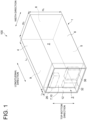
FIG. 1 is a schematic perspective view of a reefer container according to one embodiment of the present disclosure. -
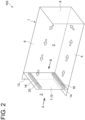
FIG. 2 is a schematic perspective view of the reefer container shown inFIG. 1 viewed from a different direction. -
FIG. 3 is a diagram schematically showing a circuit of a refrigerator of the reefer container according to one embodiment of the present disclosure. -
FIG. 4 is a view of the reefer container according to one embodiment of the present disclosure viewed from a direction indicated by an arrow A inFIG. 2 . -
FIG. 5 is a view of the reefer container shown inFIG. 4 viewed from a direction indicated by an arrow B inFIG. 2 . -
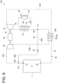
FIG. 6 is a diagram schematically showing a circuit of the refrigerator of the reefer container according to one embodiment of the present disclosure. -
FIG. 7 is a diagram schematically showing a circuit of the refrigerator of the reefer container according to one embodiment of the present disclosure. -
FIG. 8 is a diagram schematically showing a circuit of the refrigerator of the reefer container according to one embodiment of the present disclosure. -
FIG. 9 is a diagram schematically showing a circuit of the refrigerator of the reefer container according to one embodiment of the present disclosure. -
FIG. 10 is a diagram schematically showing a circuit of the refrigerator of the reefer container according to one embodiment of the present disclosure. -
FIG. 11 is a view of the reefer container according to one embodiment of the present disclosure viewed from the direction indicated by the arrow A inFIG. 2 . -
FIG. 12 is a diagram schematically showing a circuit of the refrigerator of the reefer container according to one embodiment of the present disclosure. -
FIG. 13 is a schematic sectional view of a warmed gas flow controller of the reefer container according to one embodiment of the present disclosure. -
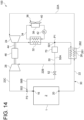
FIG. 14 is a diagram schematically showing a circuit of the refrigerator of the reefer container according to one embodiment of the present disclosure. -
FIG. 15 is a diagram schematically showing a circuit of the refrigerator of the reefer container according to one embodiment of the present disclosure. -
FIG. 16 is a schematic view of a deodorizing device of the reefer container according to one embodiment of the present disclosure. - Some embodiments of the present disclosure will now be described in detail with reference to the accompanying drawings. It is intended, however, that dimensions, materials, shapes, relative positions and the like of components described as embodiments or illustrated in the drawings shall be interpreted as illustrative only and not limitative of the scope of the present disclosure.
-
FIG. 1 is a schematic perspective view of areefer container 100 according to one embodiment of the present disclosure.FIG. 2 is a schematic perspective view of thereefer container 100 shown inFIG. 1 viewed from a different direction. InFIG. 2 , some walls forming thereefer container 100 are omitted to show the inside of thereefer container 100. - As shown in
FIGS. 1 and2 , thereefer container 100 includes acontainer body 1 having aninternal space 2 available for storing goods such as cargo therein. Thereefer container 100 is configured to allow cooling of a gas such as air inside the container body 1 (namely, in the internal space 2). Thecontainer body 1 has a plurality ofwalls 4 to 9 forming theinternal space 2. Each of the plurality ofwalls 4 to 9 separates theinternal space 2 in thecontainer body 1 and anexternal space 3 external to thecontainer body 1. The plurality ofwalls 4 to 9 includes aceiling wall 4, abottom wall 5, a pair of short-side walls 6, 7, and a pair of long-side walls - The
container body 1 may be a transport container used to transport cargo, etc. Thecontainer body 1 may be a standard transport container such as a 10-ft container, a 20-ft container, or a 40-ft container. -
FIG. 3 is a diagram schematically showing a circuit of a refrigerator (refrigeration cycle) of thereefer container 100 according to one embodiment of the present disclosure.FIG. 4 is a view of thereefer container 100 according to one embodiment of the present disclosure viewed from a direction indicated by an arrow A inFIG. 2 (from a longitudinal direction of the container body 1).FIG. 5 is a view of thereefer container 100 shown inFIG. 4 viewed from inside thecontainer body 1 and from a direction indicated by an arrow B inFIG. 2 (from an opposite direction toFIG. 4 ). - As shown in
FIGS. 2 to 5 , theinternal space 2 in thecontainer body 1 is provided with ablowout unit 14 including a blowout port 16 (opening) for blowing a gas such as air into thecontainer body 1, and asuction unit 18 including a suction port 20 (opening) for suctioning the gas such as air inside thecontainer body 1. Illustrations of theblowout unit 14 and thesuction unit 18 are omitted fromFIGS. 3 to 5 . - As shown in
FIGS. 3 to 5 , thereefer container 100 includes acirculation line 22 having the above-describedsuction port 20 andblowout port 16, acompressor 24, aheat exchanger 26, and anexpander 28. Each of thecompressor 24, theheat exchanger 26, and theexpander 28 is provided in thecirculation line 22. Thecirculation line 22, thecompressor 24, theheat exchanger 26, and theexpander 28 form a refrigerator (refrigeration cycle) 30 that extracts an internal gas corresponding to a gas inside thecontainer body 1 and uses the extracted internal gas as a heating medium. Thereefer container 100 is capable of adjusting the temperature of the internal gas using therefrigerator 30. - The
circulation line 22 is a passage extending from thesuction port 20 to theblowout port 16, and is configured to cause a circulating gas to flow therethrough corresponding to a gas suctioned from inside thecontainer body 1 through thesuction port 20. Thecompressor 24 is configured to compress the gas (circulating gas) suctioned from inside thecontainer body 1 into thecirculation line 22 through thesuction port 20. By driving thecompressor 24, the gas inside the container body 1 (internal gas) is suctioned into thecirculation line 22 through thesuction port 20. The circulating gas compressed by thecompressor 24 is increased in temperature and pressure compared to a state before being introduced into thecompressor 24 to become a high temperature and pressure gas. - The
heat exchanger 26 is configured to cool the high temperature and pressure circulating gas compressed by thecompressor 24. Theexpander 28 is configured to expand the circulating gas cooled by theheat exchanger 26. The low temperature circulating gas expanded by theexpander 28 is guided along thecirculation line 22 to theblowout port 16, and is blown from thecirculation line 22 into thecontainer body 1 through theblowout port 16. - The
circulation line 22 includes a suctionedgas line 22A for guiding the circulating gas suctioned through thesuction port 20 to thecompressor 24, acompressed gas line 22B for guiding the circulating gas compressed by thecompressor 24 to theexpander 28, and an expandedgas line 22C for guiding the circulating gas expanded by theexpander 28 to theblowout port 16. - The
heat exchanger 26 is configured to exchange heat between the circulating gas flowing through the suctionedgas line 22A and the circulating gas flowing through the compressedgas line 22B. The circulating gas flowing through the compressedgas line 22B is compressed by thecompressor 24 to become higher in temperature than the circulating gas flowing through the suctionedgas line 22A. As a result of the heat exchange by theheat exchanger 26, the circulating gas flowing through the compressedgas line 22B is cooled with the circulating gas flowing through the suctionedgas line 22A and the circulating gas flowing through the suctionedgas line 22A is heated with the circulating gas flowing through the compressedgas line 22B. In other words, theheat exchanger 26 includes a low-temperature sideheat exchange part 261 provided in the suctionedgas line 22A and causing the circulating gas to flow therethrough, and a high-temperature sideheat exchange part 262 provided in the compressedgas line 22B and causing the circulating gas to flow therethrough, and is configured to move heat from the circulating gas flowing through the high-temperature sideheat exchange part 262 to the circulating gas flowing through the low-temperature sideheat exchange part 261. - As shown in
FIGS. 3 and4 , thereefer container 100 may further include a cooler 32 provided between thecompressor 24 and the heat exchanger 26 (high-temperature side heat exchange part 262) in thecirculation line 22. The cooler 32 is provided upstream from theheat exchanger 26 in the compressedgas line 22B and configured to exchange heat between the circulating gas flowing through the compressedgas line 22B (circulation line 22) and a coolant (for example, water) lower in temperature than this circulating gas. As a result of the heat exchange by the cooler 32, the circulating gas flowing through the compressedgas line 22B toward theheat exchanger 26 is cooled with the coolant. The circulating gas cooled by the cooler 32 is introduced into the heat exchanger 26 (high-temperature side heat exchange part 262) through the compressedgas line 22B. - In the embodiments shown in
FIGS. 3 and4 , thereefer container 100 further includes acoolant circulation line 34 for causing the coolant to circulate therethrough. The coolant is supplied to the cooler 32 through thecoolant circulation line 34. More specifically, thecoolant circulation line 34 is provided with aradiator 38 forming acooling device 36 for cooling the coolant, and apump 42 for feeding the coolant along thecoolant circulation line 34. Thecooling device 36 includes theradiator 38 and afan 40 for air-cooling theradiator 38. After the coolant is increased in temperature as a result of the heat exchange with the circulating gas flowing through the compressedgas line 22B by the cooler 32, the coolant is fed by thepump 42 to thecoolant circulation line 34 and cooled by the coolingdevice 36 including theradiator 38. The coolant cooled by the coolingdevice 36 is supplied to the cooler 32 through thecoolant circulation line 34. The refrigerant circulating through thecoolant circulation line 34 is not limited to a liquid form but may be a gaseous form. The refrigerant circulating through thecoolant circulation line 34 may be a fluorine-based refrigerant (refrigerant gas) such as R-1234ZE, for example, or may be an antifreeze liquid such as glycol water, for example. The refrigerant circulating through thecoolant circulation line 34 preferably has a lower freezing point than water. - In some embodiments, the
expander 28 may be coupled to thecompressor 24 via arotational shaft 44. In the embodiments shown inFIGS. 3 and4 , thereefer container 100 further includes anelectric motor 46 configured to generate driving force for driving thecompressor 24. Thecompressor 24 includes an electric compressor configured to compress the circulating gas by being driven by theelectric motor 46. Thecompressor 24 and theexpander 28 are arranged coaxially with each other via therotational shaft 44 as an output shaft of theelectric motor 46 for driving thecompressor 24, and are each connected to therotational shaft 44. Theelectric motor 46 is supplied with a current from a power source (such as a generator) not shown in the drawings, and is driven by the current supplied from the power source to drive therotational shaft 44, thecompressor 24, and theexpander 28. At theexpander 28, part of expansion energy generated during gas expansion is recovered, and the recovered expansion energy is used for assisting in driving of thecompressor 24. - As shown in
FIG. 4 , each of the suctionedgas line 22A, thecompressed gas line 22B, and the expandedgas line 22C is formed using pipes. The respective pipes forming thecirculation line 22 may be a plurality of pipe sections connected via flanges, etc. - In the embodiment shown in
FIG. 4 , the pipes forming the suctionedgas line 22A include apipe 23A provided between thesuction port 20 and an inlet of theheat exchanger 26, and apipe 23B provided between an outlet of theheat exchanger 26 and thecompressor 24. The pipes forming thecompressed gas line 22B include apipe 23C provided between an outlet of thecompressor 24 and an inlet of the cooler 32, apipe 23D provided between an outlet of the cooler 32 and the inlet of theheat exchanger 26, and apipe 23E provided between the outlet of theheat exchanger 26 and an inlet of theexpander 28. The pipe forming the expandedgas line 22C includes apipe 23F provided between an outlet of theexpander 28 and theblowout port 16. - Each of
FIGS. 6 to 10 andFIG. 12 is a diagram schematically showing a circuit of therefrigerator 30 of thereefer container 100 according to one embodiment of the present disclosure.FIG. 11 is a view of thereefer container 100 according to one embodiment of the present disclosure (thereefer container 100 shown inFIG. 12 ) viewed from the direction indicated by the arrow A inFIG. 2 . - As shown in
FIGS. 3 ,4 , and6 to 12 , thereefer container 100 according to some embodiments includes the above-describedcontainer body 1, the above-describedcirculation line 22, the above-describedcompressor 24, the above-describedheat exchanger 26, the above-describedexpander 28, and a warmedgas introduction line 50. - The warmed
gas introduction line 50 forms at least a part of a flow path for extracting the circulating gas higher in temperature than the internal gas from between thecompressor 24 and the heat exchanger 26 (high-temperature side heat exchange part 262) in thecirculation line 22 and guiding the extracted circulating gas to thecontainer body 1. As shown inFIGS. 4 and9 , parts of the warmedgas introduction line 50 are formed using respective pipes. The respective pipes forming the warmedgas introduction line 50 may be a plurality of pipe sections connected via flanges, etc. - The circulating gas flowing between the
compressor 24 and the heat exchanger 26 (high-temperature side heat exchange part 262) in thecirculation line 22 is compressed by thecompressor 24 to be increased in temperature and pressure, thereby becoming the circulating gas higher in temperature and pressure than the internal gas. Guiding the circulating gas thereby brought to higher temperature and pressure than the internal gas into thecontainer body 1 through the warmedgas introduction line 50 allows a temperature inside the container to be increased. - The
refrigerator 30 constructed by the above-described configuration includes thecompressor 24, theheat exchanger 26, and theexpander 28 each provided in thecirculation line 22, and uses the gas inside the container body 1 (internal gas) as a heating medium. The gas inside thecontainer body 1 is caused to circulate naturally from theblowout port 16 to thesuction port 20 as a result of a difference between a pressure at theblowout port 16 and a pressure at thesuction port 20, thereby eliminating a need for a fan for circulation of internal air. This does not cause increase in a temperature inside the container due to provision of a fan and a fan motor inside thecontainer body 1. Thus, a temperature inside the container is easily maintained at an intended temperature. The absence of a fan and a fan motor inside thecontainer body 1 makes it possible to ensure a wide cargo space inside thecontainer body 1. Thus, the above-described configuration provides thereefer container 100 capable of suppressing reduction in a cargo space inside the container and capable of maintaining a temperature inside the container stably. - According to the above-described configuration, the circulating gas brought to a higher temperature than the internal gas by the
compressor 24 is returned to the inside of thecontainer body 1 through the warmedgas introduction line 50, thereby allowing a temperature inside the container to be increased. By the provision of the warmedgas introduction line 50 outside thecontainer body 1, thereefer container 100 becomes capable of expanding a range where a temperature inside the container is adjustable to a higher temperature side while suppressing reduction in a cargo space inside the container. - As shown in
FIGS. 3 ,4 , and6 to 12 , in some embodiments, the above-describedreefer container 100 further includes at least one warmed gas flow controller (warmed gas flow control valve) 52 provided in the warmedgas introduction line 50 and configured to allow control of the flow rate of the circulating gas flowing through the warmedgas introduction line 50. The warmedgas flow controller 52 is configured to allow control of the flow rate of the circulating gas to be guided downstream from the warmed gas flow controller 52 (toward a downstream end 502) by changing a degree of opening of a valve element arranged in the warmedgas introduction line 50. The warmedgas flow controller 52 may be an on-off valve controllable in a degree of opening to a fully-closed state and a fully-open state, or may be an opening control valve controllable in a degree of opening to a fully-closed state, a fully-open state, and at least one intermediate degree of opening between the fully-closed state and the fully-opened state. - In the embodiments shown in
FIGS. 3 ,4 ,6 to 8 ,11 , and12 , by closing the warmed gas flow controller 52 (by reducing a degree of opening of the valve element) while therefrigerator 30 is operating, the circulating gas flowing through the compressedgas line 22B is guided to theexpander 28, decreased in temperature through the expansion by theexpander 28, and then guided into thecontainer body 1. By opening the warmed gas flow controller 52 (by increasing a degree of opening of the valve element) while therefrigerator 30 is operating, pressure loss at the inlet of theexpander 28 becomes larger than that at the warmedgas introduction line 50 or at the warmedgas flow controller 52. Then, as a result of a difference between a pressure at anupstream end 501 and a pressure at thedownstream end 502 of the warmedgas introduction line 50, the circulating gas flowing through the compressedgas line 22B is guided into thecontainer body 1 through the warmedgas introduction line 50. This eliminates a need for a fan for guiding the circulating gas into thecontainer body 1 through the warmedgas introduction line 50. - According to the above-described configuration, it is possible to control temperature increase inside the
container body 1 by controlling the flow rate of the warmed gas (circulating gas) flowing through the warmedgas introduction line 50 using the warmedgas flow controller 52. In this case, this control of the temperature increase can be exerted simply. Increasing and reducing an output from the electric motor 46 (the number of rotations thereof) increases and reduces the flow rate of the circulating gas to be ejected from thecompressor 24 and to flow through the compressedgas line 22B. For this reason, in addition to a degree of opening of the warmedgas flow controller 52, an output from the electric motor 46 (the number of rotations thereof) is preferably used as a parameter for controlling temperature increase inside thecontainer body 1. - In the embodiments shown in
FIGS. 9 and10 , the above-describedreefer container 100 further includes at least one circulating gas flow controller (circulating gas flow control valve) 29 provided in thecirculation line 22 bypassed by the warmedgas introduction line 50 and configured to allow control of the flow rate of the circulating gas flowing through thiscirculation line 22. Here, thecirculation line 22 bypassed by the warmedgas introduction line 50 is a segment of thecirculation line 22 between a connection position P1 or P2 to which theupstream end 501 of the warmedgas introduction line 50 is connected and a connection position P4 to which thedownstream end 502 of the warmedgas introduction line 50 is connected. In the embodiments shown inFIGS. 9 and10 , the circulatinggas flow controller 29 is provided between the heat exchanger 26 (high-temperature side heat exchange part 262) and the connection position P4 in thecirculation line 22. Alternatively, the circulatinggas flow controller 29 may be provided between the connection position P1 or P2 and the heat exchanger 26 (high-temperature side heat exchange part 262) in thecirculation line 22. - The circulating
gas flow controller 29 is configured to allow control of the flow rate of the circulating gas to be guided downstream from the circulating gas flow controller 29 (toward the expander 28) by changing a degree of opening of a valve element arranged in thecirculation line 22 bypassed by the warmedgas introduction line 50. The circulatinggas flow controller 29 may be an on-off valve controllable in a degree of opening to a fully-closed state and a fully-open state, or may be an opening control valve controllable in a degree of opening to a fully-closed state, a fully-open state, and at least one intermediate degree of opening between the fully-closed state and the fully-opened state. - In the embodiments shown in
FIGS. 9 and10 , by opening the circulating gas flow controller 29 (by increasing a degree of opening of the valve element) and closing the warmed gas flow controller 52 (by reducing a degree of opening of the valve element) while therefrigerator 30 is operating, the circulating gas flowing through the compressedgas line 22B is guided to theexpander 28, decreased in temperature through the expansion by theexpander 28, and then guided into thecontainer body 1. By closing the circulating gas flow controller 29 (by reducing a degree of opening of the valve element) and opening the warmed gas flow controller 52 (by increasing a degree of opening of the valve element) while therefrigerator 30 is operating, pressure loss at the circulatinggas flow controller 29 provided in thecirculation line 22 bypassed by the warmedgas introduction line 50 becomes larger than that at the warmedgas introduction line 50 or at the warmedgas flow controller 52. Then, as a result of a difference between a pressure at theupstream end 501 and a pressure at thedownstream end 502 of the warmedgas introduction line 50, the circulating gas flowing through the compressedgas line 22B is guided into thecontainer body 1 through the warmedgas introduction line 50. This eliminates a need for a fan for guiding the circulating gas into thecontainer body 1 through the warmedgas introduction line 50. - According to the above-described configuration, it is possible to control temperature increase inside the
container body 1 by controlling the flow rate of the warmed gas (circulating gas) flowing through the warmedgas introduction line 50 using the warmedgas flow controller 52 and the circulatinggas flow controller 29. In this case, this control of the temperature increase can be exerted simply. - As shown in
FIGS. 3 ,4 ,6 ,7 ,9 ,11 , and12 , in some embodiments, theupstream end 501 of the warmedgas introduction line 50 described above is connected to the compressedgas line 22B (pipe 23D) at the connection position P1 located between the cooler 32 and the heat exchanger 26 (high-temperature side heat exchange part 262) in the compressedgas line 22B (circulation line 22). In this case, the circulating gas cooled by the cooler 32 is introduced into the warmedgas introduction line 50. - In the illustrated embodiment, the pipes forming the warmed
gas introduction line 50 include apipe 55A provided between the connection position P1 in thepipe 23D (compressedgas line 22B) and an inlet of the warmedgas flow controller 52. Thepipe 55A has the above-describedupstream end 501. - In one embodiment, the circulating gas increased in pressure by the
compressor 24 is brought to a high temperature of equal to or greater than 100°C. The circulating gas cooled by the cooler 32 is brought to an ordinary temperature of equal to or greater than 0°C and equal to or less than 60°C. In this case, the circulating gas at the ordinary temperature and the high pressure is introduced into thecontainer body 1 through the warmedgas introduction line 50. - According to the above-described configuration, the circulating gas brought to a high temperature by the
compressor 24 is cooled by the cooler 32, making it possible to reduce a temperature difference between the circulating gas (warmed gas) introduced into thecontainer body 1 through the warmedgas introduction line 50 and the internal gas. Reducing this temperature difference allows the internal gas to be increased gently in temperature using the above-described warmed gas. This makes it possible to suppress damage due to thermal strain inside thecontainer body 1. - As shown in
FIGS. 8 and10 , in some embodiments, theupstream end 501 of the warmedgas introduction line 50 described above is connected to the compressedgas line 22B (pipe 23C) at the connection position P2 located between thecompressor 24 and the cooler 32 in the compressedgas line 22B (circulation line 22). - In the illustrated embodiment, the pipes forming the warmed
gas introduction line 50 include apipe 55B provided between the connection position P2 in thepipe 23C (compressedgas line 22B) and the inlet of the warmedgas flow controller 52. Thepipe 55B has the above-describedupstream end 501. - In one embodiment, the circulating gas increased in pressure by the
compressor 24 is brought to a high temperature of equal to or greater than 100°C. In this case, the circulating gas at the high temperature and the high pressure not cooled by the cooler 32 is introduced into thecontainer body 1 through the warmedgas introduction line 50. - If the circulating gas having passed through the cooler 32 is introduced as warmed gas into the
container body 1, temperature change to be caused by the cooler 32 is required to be considered in exerting temperature increase control inside thecontainer body 1. According to the above-described configuration, the circulating gas brought to a high temperature by thecompressor 24 is introduced as warmed gas into thecontainer body 1 without passing through the cooler 32. In this case, temperature change to be caused by the cooler 32 is not required to be considered in exerting temperature increase control inside thecontainer body 1, so that this temperature increase control can be exerted simply. - As shown in
FIG. 3 , in some embodiments, a blowout port 503 (opening) is formed at thedownstream end 502 of the warmedgas introduction line 50 described above for blowing a gas such as air into thecontainer body 1. The above-describedsuction unit 18 may include thesuction port 20 and theblowout port 503. The circulating gas flowing through the warmedgas introduction line 50 is guided to theblowout port 503 and blown from the warmedgas introduction line 50 into thecontainer body 1 through theblowout port 503. - In the illustrated embodiment, the pipes forming the warmed
gas introduction line 50 include the above-describedpipe 55A, and apipe 56A provided between an outlet of the warmedgas flow controller 52 and theblowout port 503. Thepipe 56A has the above-describeddownstream end 502. The pipes forming the warmedgas introduction line 50 may include the above-describedpipe 55B and the above-describedpipe 56A. - As shown in
FIGS. 6 to 8 ,11 , and12 , in some embodiments, thedownstream end 502 of the warmedgas introduction line 50 described above is connected to the expandedgas line 22C (pipe 23F) at a connection position P3 located between theexpander 28 and theblowout port 16 in the circulation line 22 (expandedgas line 22C). The circulating gas flowing through the warmedgas introduction line 50 is introduced into thecontainer body 1 through a position in the expandedgas line 22C downstream from the connection position P3. - In the illustrated embodiment, the pipes forming the warmed
gas introduction line 50 include either one of thepipe 55A and thepipe 55B described above, and apipe 56B provided between the outlet of the warmedgas flow controller 52 and the connection position P3 in thepipe 23F (expandedgas line 22C). Thepipe 56B has the above-describeddownstream end 502. - According to the above-described configuration, a part of the
circulation line 22 such as the blowout port 16 (a part of the expandedgas line 22C between the connection position P3 and the blowout port 16) is available as a flow path for the warmed gas (the circulating gas flowing through the warmed gas introduction line 50). In this case, it is not required to provide theblowout port 503 dedicated to introduction of the warmed gas into thecontainer body 1, making it possible to encourage compactness and weight reduction of the construction of thereefer container 100. - According to the above-described configuration, the
circulation line 22 bypassed by the warmedgas introduction line 50 is subjected to large pressure loss by theexpander 28 provided in thiscirculation line 22. This allows a large quantity of the circulating gas to be guided toward the warmedgas introduction line 50 when the warmedgas introduction line 50 is open. This configuration does not require the above-described circulatinggas flow controller 29. Furthermore, the circulating gas passing through the warmedgas introduction line 50 is at a higher temperature than the circulating gas passing through thecirculation line 22 bypassed by the warmedgas introduction line 50. Thus, the above-described configuration allows a large quantity of the circulating gas at a relatively high temperature to be guided into thecontainer body 1 through the warmedgas introduction line 50, making it possible to provide large heating capacity inside thecontainer body 1. - As shown in
FIGS. 9 and10 , in some embodiments, thedownstream end 502 of the warmedgas introduction line 50 described above is connected to the compressedgas line 22B at the connection position P4 located between the heat exchanger 26 (high-temperature side heat exchange part 262) and theexpander 28 in the compressedgas line 22B (circulation line 22). The circulating gas flowing through the warmedgas introduction line 50 is introduced into thecontainer body 1 through a part of the compressedgas line 22B downstream from the connection position P4, theexpander 28, and the expandedgas line 22C. - In the illustrated embodiment, the pipes forming the warmed
gas introduction line 50 include either one of thepipe 55A and thepipe 55B described above, and apipe 56C provided between the outlet of the warmedgas flow controller 52 and the connection position P4 in the compressedgas line 22B. Thepipe 56C has the above-describeddownstream end 502. - According to the above-described configuration, a part of the
circulation line 22 such as the blowout port 16 (a part of thecirculation line 22 between the connection position P4 and the blowout port 16) is available as a flow path for the warmed gas (the circulating gas flowing through the warmed gas introduction line 50). In this case, it is not required to provide theblowout port 503 dedicated to introduction of the warmed gas into thecontainer body 1, making it possible to encourage compactness and weight reduction of the construction of thereefer container 100. - According to the above-described configuration, the
downstream end 502 of the warmedgas introduction line 50 is connected to a position in thecirculation line 22 upstream from theexpander 28. Thus, compared to a case where thedownstream end 502 is connected to a position in thecirculation line 22 downstream from theexpander 28, it is possible to reduce heat input from the warmedgas introduction line 50 to a part of thecirculation line 22 downstream from theexpander 28, thereby increasing a gain of cooling performance during refrigerating operation of thereefer container 100. - As shown in
FIGS. 1 ,4 , and11 , in some embodiments, thecompressor 24, the cooler 32, theheat exchanger 26, and theexpander 28, each provided in thecirculation line 22, are arranged in theexternal space 3 external to thecontainer body 1 and along a partition wall 10 separating theinternal space 2 in thecontainer body 1 and theexternal space 3. - In the illustrated embodiment, the above-described devices provided in the
circulation line 22 are arranged along the short-side wall 7 functioning as the partition wall 10. InFIG. 1 , some of these devices provided in thecirculation line 22 are shown schematically by double-dotted chain lines. - As shown in
FIGS. 1 ,4 , and11 , the above-describedreefer container 100 may include acover 12 provided in such a manner as to enclose the above-described devices in theexternal space 3 external to thecontainer body 1 from above, below, and sides. - As shown in
FIGS. 4 and5 , thepipe 23A between thesuction port 20 and theheat exchanger 26 may be provided in such a manner as to pass through a throughhole 25 formed at the short-side wall 7 (partition wall 10). Furthermore, thepipe 23F between theexpander 28 and theblowout port 16 may be provided in such a manner as to pass through a throughhole 27 formed at the short-side wall 7 (partition wall 10). - According to the above-described configuration, each of the
compressor 24, the cooler 32, theheat exchanger 26, and theexpander 28 is installed in theexternal space 3 external to thecontainer body 1. Specifically, as these devices are not provided in theinternal space 2 in thecontainer body 1, it is possible to ensure a wide cargo space inside the container. Furthermore, according to the above-described configuration, it is not required to provide a heat exchanger such as an evaporator in theinternal space 2 in thecontainer body 1. Thus, defrosting operation for defrosting of such a heat exchanger is unnecessary. This allows a temperature inside the container to be maintained easily at an intended temperature. Furthermore, according to the above-described configuration, the devices forming therefrigerator 30 are arranged in a relatively narrow space in theexternal space 3 external to thecontainer body 1 and along the partition wall 10. As therefrigerator 30 added to thecontainer body 1 is installed in a small area in this way, thereefer container 100 including therefrigerator 30 is favorably available as a container for purposes such as transportation. - As shown in
FIGS. 1 ,4 , and11 , in some embodiments, thecompressor 24, the cooler 32, theheat exchanger 26, and theexpander 28, each provided in thecirculation line 22, are arranged in theexternal space 3 external to thecontainer body 1 and along the partition wall 10 separating theinternal space 2 in thecontainer body 1 and theexternal space 3. Thecirculation line 22 and the warmedgas introduction line 50 are also arranged in theexternal space 3 and along the partition wall 10. - In a directional view vertical to an
external surface 101 of the partition wall 10 facing theexternal space 3 such as that shown inFIGS. 4 and11 , the above-described warmedgas introduction line 50 is arranged in such a manner as not to intersect a cooledgas line 22D connecting theheat exchanger 26 and theexpander 28 in thecirculation line 22 to each other. - In the illustrated embodiment, the
compressor 24 and theexpander 28 are arranged side by side in a horizontal direction. Theheat exchanger 26 and the cooledgas line 22D are arranged on an upper side (one side) in a vertical direction with respect to thecompressor 24 and theexpander 28. The cooler 32 and the warmedgas introduction line 50 are arranged on a lower side (other side) in the vertical direction with respect to thecompressor 24 and theexpander 28. In other words, the cooler 32 and the warmedgas introduction line 50 are arranged on the opposite side to theheat exchanger 26 and the cooledgas line 22D in the vertical direction across thecompressor 24 and theexpander 28. - According to the above-described configuration, it is possible to reduce heat input from the circulating gas (warmed gas) flowing through the warmed
gas introduction line 50 to the circulating gas (cooled gas) flowing through the cooledgas line 22D, making it possible to encourage performance improvement during refrigerating operation of thereefer container 100. - As shown in
FIG. 7 , in some embodiments, the above-describedreefer container 100 includes the above-described warmedgas introduction line 50 having theupstream end 501 connected between the cooler 32 and the heat exchanger 26 (high-temperature side heat exchange part 262) in thecirculation line 22, the above-describedelectric motor 46, a coolingmedium supply line 60, and a coolingmedium return line 62. The coolingmedium supply line 60 has one end connected to the warmedgas introduction line 50, and forms at least a part of a flow path for extracting the circulating gas from the warmedgas introduction line 50 and supplying the extracted circulating gas to theelectric motor 46 as a cooling medium for cooling theelectric motor 46. The coolingmedium return line 62 forms at least a part of a flow path for returning the circulating gas to a position in thecirculation line 22 upstream from thecompressor 24 after the circulating gas is supplied to theelectric motor 46 through the coolingmedium supply line 60. - In the illustrated embodiment, an upstream end (one end) of the cooling
medium supply line 60 is connected to a position in the warmedgas introduction line 50 upstream from the warmed gas flow controller 52 (closer to the upstream end 501). A downstream end (one end) of the coolingmedium return line 62 is connected between the low-temperature side heat exchange part 261 (heat exchanger 26) and thecompressor 24 in thecirculation line 22. The upstream end (one end) of the coolingmedium supply line 60 may be connected between the cooler 32 and the heat exchanger 26 (high-temperature side heat exchange part 262) in thecirculation line 22. - The
reefer container 100 may include amotor cooler 64. Themotor cooler 64 receives the circulating gas cooled by the cooler 32 and guided through the coolingmedium supply line 60. Themotor cooler 64 is configured to exchange heat between theelectric motor 46 and the circulating gas at a lower temperature than theelectric motor 46 guided to themotor cooler 64. As a result of the heat exchange by themotor cooler 64, theelectric motor 46 is cooled with the circulating gas guided to themotor cooler 64. The circulating gas having been used in themotor cooler 64 for cooling theelectric motor 46 is returned through the coolingmedium return line 62 to a position in thecirculation line 22 upstream from thecompressor 24. - According to the above-described configuration, by the provision of the cooling
medium supply line 60 and the coolingmedium return line 62, thereefer container 100 becomes capable of cooling theelectric motor 46 with the circulating gas extracted from the warmedgas introduction line 50 and returning the circulating gas having been used for cooling theelectric motor 46 to thecirculation line 22. In this case, thecirculation line 22, the warmedgas introduction line 50 and the like are available in part as a flow path for the cooling medium (circulating gas) for cooling theelectric motor 46, making it possible to encourage compactness and weight reduction of the configuration of thereefer container 100. -
FIG. 13 is a schematic sectional view of the warmed gas flow controller 52 (53, 54) of the reefer container according to one embodiment of the present disclosure. - As shown in
FIGS. 11 to 13 , in some embodiments, the at least one warmed gas flow controller (warmed gas flow control valve) 52 described above includes a first warmed gas flow controller (warmed gas flow control valve) 53 provided in the warmedgas introduction line 50, and a second warmed gas flow controller (warmed gas flow control valve) 54 provided downstream from the first warmed gas flow controller 53 (closer to the downstream end 502) in the warmedgas introduction line 50. The first warmedgas flow controller 53 and the second warmedgas flow controller 54 are also applicable to the above-described embodiments shown inFIGS. 1 to 10 . - The first warmed
gas flow controller 53 and the second warmedgas flow controller 54 are configured to allow control of the flow rate of the circulating gas to be guided downstream from the warmed gas flow controller 52 (53, 54) (toward the downstream end 502) by changing degrees of opening ofvalve elements gas introduction line 50. Each of the first warmedgas flow controller 53 and the second warmedgas flow controller 54 may be an on-off valve controllable in a degree of opening to a fully-closed state and a fully-open state, or may be an opening control valve controllable in a degree of opening to a fully-closed state, a fully-open state, and at least one intermediate degree of opening between the fully-closed state and the fully-opened state. - According to the above-described configuration, providing the two warmed
gas flow controllers gas introduction line 50 makes it possible to improve heat shielding performance in the warmedgas introduction line 50. As a result, it is possible to reduce heat input to a part of the warmedgas introduction line 50 downstream from the second warmedgas flow controller 54 when the two warmedgas flow controllers - In the embodiment shown in
FIG. 13 , the first warmedgas flow controller 53 and the second warmedgas flow controller 54 haveflange parts flange part 542 and theflange part 532, theflange part 542 is fastened to theflange part 532 via a fastening member (in the illustrated example, a bolt and a nut) 522. Providing the packing 521 between the two warmedgas flow controllers gas introduction line 50. This makes it possible to reduce heat input to a part of the warmedgas introduction line 50 downstream from the second warmedgas flow controller 54 when the two warmedgas flow controllers - Each of
FIGS. 14 and15 is a diagram schematically showing a circuit of therefrigerator 30 of thereefer container 100 according to one embodiment of the present disclosure.FIG. 16 is a schematic view of adeodorizing device 70 of thereefer container 100 according to one embodiment of the present disclosure. - As shown in
FIGS. 14 and15 , in some embodiments, the above-describedreefer container 100 further includes thedeodorizing device 70 configured to emit a substance having a deodorizing function to the circulating gas. This is also applicable to the above-described embodiments shown inFIGS. 1 to 13 . - The
deodorizing device 70 is preferably configured to generate the substance having a deodorizing function from the circulating gas. In the embodiment shown inFIG. 16 , the internal gas and the circulating gas contain air, and thedeodorizing device 70 includes an ozone generator 70A configured to generate ozone from the air in the circulating gas. The ozone generator 70A includeselectrodes electrodes electrodes electrodes - The
deodorizing device 70 may be configured to generate a substance originating from moisture and having a deodorizing function by applying a high voltage or emitting an ultrasonic wave, for example, to at least one of moisture in the circulating gas and water stored in thedeodorizing device 70. The substance originating from moisture and having a deodorizing function may be a charged microparticle. - The
deodorizing device 70 is configured to degerm and deodorize the circulating gas by emitting ozone or the substance originating from moisture and having a deodorizing function to the circulating gas. The circulating gas (air) flowing through the above-describedcirculation line 22 or warmedgas introduction line 50 is dry. Thus, it is easy to generate the substance having a deodorizing function to achieve high deodorizing effect using the substance having a deodorizing function. - According to the above-described configuration, it is possible to deodorize the circulating gas by causing the
deodorizing device 70 to emit the substance having a deodorizing function to the circulating gas. It is also possible to deodorize the internal gas by returning the circulating gas deodorized by thedeodorizing device 70 into thecontainer body 1. In this case, thedeodorizing device 70 can be provided outside thecontainer body 1 unlike in a case where the internal gas is to be deodorized directly by thedeodorizing device 70, making it possible to ensure a wide cargo space inside thecontainer body 1. In providing thedeodorizing device 70 outside thecontainer body 1, thedeodorizing device 70 is preferably provided in a line such as thecirculation line 22 or the warmedgas introduction line 50 through which the gas (circulating gas) extracted from inside thecontainer body 1 is to flow. In this case, a line such as thecirculation line 22 or the warmedgas introduction line 50 is available as a flow path for a fluid between thecontainer body 1 and thedeodorizing device 70, making it possible to encourage compactness and weight reduction of the construction of thereefer container 100. - As shown in
FIG. 14 , in some embodiments, the above-describeddeodorizing device 70 is provided in the warmedgas introduction line 50. In the embodiment shown inFIG. 14 , thedeodorizing device 70 is installed upstream from the warmed gas flow controller 52 (closer to the upstream end 501) in the warmedgas introduction line 50. - According to the above-described configuration, providing the
deodorizing device 70 in the warmedgas introduction line 50 makes it possible to reduce a likelihood that the substance having a deodorizing function will be guided to theexpander 28 in a low-temperature environment. Thus, it is possible to reduce a likelihood that the substance having a deodorizing function will be less effective or will be frozen in theexpander 28. As a result, even if the quantity of the substance having a deodorizing function to be emitted from thedeodorizing device 70 is reduced, deodorizing effect is still achieved actively. Furthermore, by providing thedeodorizing device 70 in the warmedgas introduction line 50, the substance having a deodorizing function is guided into thecontainer body 1. This allows the internal gas to be degermed and deodorized directly with the substance having a deodorizing function. - As shown in
FIG. 15 , in some embodiments, the above-describeddeodorizing device 70 is installed in ordinary-temperature environment areas in thecirculation line 22 through which the circulating gas at an ordinary temperature (equal to or greater than 0°C and equal to or less than 60°C) flows. In the embodiment shown inFIG. 15 , the above-describeddeodorizing device 70 may be installed between the cooler 32 and the heat exchanger 26 (high-temperature side heat exchange part 262) in thecirculation line 22, which is one of these ordinary-temperature environment areas. The above-describeddeodorizing device 70 may be installed between the low-temperature side heat exchange part 261 (heat exchanger 26) and thecompressor 24 in thecirculation line 22, which is one of these ordinary-temperature environment areas. - According to the above-described configuration, providing the
deodorizing device 70 in the above-described ordinary-temperature environment area in thecirculation line 22 makes it possible to reduce a likelihood that the substance having a deodorizing function will be guided to theexpander 28 in a low-temperature environment. Thus, it is possible to reduce a likelihood that the substance having a deodorizing function will be less effective or will be frozen in theexpander 28. As a result, even if the quantity of the substance having a deodorizing function to be emitted from thedeodorizing device 70 is reduced, deodorizing effect is still achieved actively. In particular, a pressure is relatively low between the low-temperature side heat exchange part 261 (heat exchanger 26) and thecompressor 24 in thecirculation line 22, so that the substance having a deodorizing function is emitted easily to the circulating gas. Furthermore, even in thereefer container 100 where the internal gas is cooled to an ultra low temperature of equal to or less than -40°C, the circulating gas still flows as ordinary-temperature dry air between the low-temperature side heat exchange part 261 (heat exchanger 26) and thecompressor 24 in thecirculation line 22. Thus, it is easy to generate the substance having a deodorizing function to achieve high deodorizing effect using the substance having a deodorizing function. - In some embodiments, at least one of the above-described
heat exchanger 26 and cooler 32 may include a plate heat exchanger or a microchannel heat exchanger. The plate heat exchanger or the microchannel heat exchanger may be formed using a material containing aluminum or titanium. - In some embodiments, the
suction port 20 is provided with afilter part 21 such as that shown inFIG. 5 for removing a foreign matter. Thefilter part 21 includes a member with a plurality of holes or meshes, etc., and has a plurality of openings defined by these holes or meshes, for example. - As shown in
FIG. 1 , in some embodiments, the partition wall 10 (in the example shown inFIG. 1 , the short-side wall 7 of the container body 1), making a separation between a region where thecompressor 24, the cooler 32, theheat exchanger 26, and theexpander 28 are installed externally to thecontainer body 1 and theinternal space 2 in thecontainer body 1, extends along a plane perpendicular to the longitudinal direction of thecontainer body 1. - In the above-described embodiment, the devices (
compressor 24,heat exchanger 26, expander 28) forming therefrigerator 30 are arranged in a relatively narrow space along the partition wall 10 (short-side wall 7) that is a relatively small wall extending along the plane perpendicular to the longitudinal direction of thecontainer body 1. This allows reduction in an installation area for therefrigerator 30 to be added to thecontainer body 1, thereby making thereefer container 100 including therefrigerator 30 favorably available as a container for purposes such as transportation. - In one embodiment, the
compressor 24, the cooler 32, theheat exchanger 26, andexpander 28 arranged in theexternal space 3 may be located within a range where a length L1 from the partition wall 10 in the longitudinal direction of thecontainer body 1 is equal to or less than 1/10 of a length L0 of the container body 1 (seeFIG. 1 ). - In this case, an installation area for the devices forming the
refrigerator 30 is within the range of equal to or less than 1/10 of the length L0 of thecontainer body 1. This results in a small installation area for therefrigerator 30 to be added to thecontainer body 1, thereby making thereefer container 100 including therefrigerator 30 favorably available as a container for purposes such as transportation. - If the
container body 1 is a 20-ft container (length L0: approximately 6.1 m, width WO: approximately 2.4 m, height H0: approximately 2.6 m), for example, the length (L1) of the above-described installation area may be equal to or less than 610 mm. - In the present description, an expression indicating relative or absolute arrangement such as "in one direction," "along one direction," "parallel," "perpendicular," "center," "concentric," or "coaxial" shall not be construed as indicating only such arrangement in a strict sense, but shall also be construed as including a state where the arrangement is relatively displaced by a tolerance, or by such an angle or such a distance as will provide the same function.
- As an example, an expression indicating an equal state between matters such as "same," "equal," or "uniform" shall not be construed as indicating only a state where the matters are strictly equal, but shall also be construed as including a state in the presence of a tolerance or such a difference as will provide the same function.
- In the present description, an expression indicating a shape such as a rectangular shape or a cylindrical shape shall not be construed as indicating only a rectangular shape or a cylindrical shape in a geometrically strict sense, but shall also be construed as including a shape with projections and recesses or chamfered corners within a range where it is possible to provide the same function.
- In the present description, an expression "comprising," "including," or "having" one constitutional element is not an exclusive expression excluding the presence of other constitutional elements.
- The present disclosure is not limited to the above-described embodiments but also includes embodiments obtained by modifying the above-described embodiments or embodiments obtained by combining these embodiments together as appropriate.
- The contents described in some of the embodiments described above will be understood as follows, for example.
- 1) A reefer container (100) according to at least one embodiment of the present disclosure is a reefer container (100) configured to allow cooling of an internal gas corresponding to a gas inside a container body (1), comprising:
- the container body (1);
- a circulation line (22) having a suction port (20) and a blowout port (16) each provided inside the container body (1);
- a compressor (24) provided in the circulation line (22) and configured to compress a circulating gas corresponding to the gas suctioned into the circulation line (22) from inside the container body (1) through the suction port (20);
- a heat exchanger (26) provided in the circulation line (22) and configured to cool the circulating gas compressed by the compressor (24);
- an expander (28) provided in the circulation line (22) and configured to expand the circulating gas cooled by the heat exchanger (26); and
- a warmed gas introduction line (50) for extracting the circulating gas higher in temperature than the internal gas from between the compressor (24) and the heat exchanger (26) in the circulation line (22) and guiding the extracted circulating gas to the container body (1).
- A refrigerator (30) constructed by the configuration described in the above 1) includes the compressor (24), the heat exchanger (26), and the expander (28) each provided in the circulation line (22), and uses the gas inside the container body (1) (internal gas) as a heating medium. The gas inside the container body (1) is caused to circulate naturally from the blowout port (16) to the suction port (20) as a result of a difference between a pressure at the blowout port (16) and a pressure at the suction port (20), thereby eliminating a need for a fan for circulation of the circulating gas. This does not cause increase in a temperature inside the container due to provision of a fan and a fan motor inside the container body (1). Thus, a temperature inside the container is easily maintained at an intended temperature. The absence of a fan and a fan motor inside the container body (1) makes it possible to ensure a wide cargo space inside the container body (1). Thus, the configuration described in the above 1) provides the reefer container (100) capable of suppressing reduction in a cargo space inside the container and capable of maintaining a temperature inside the container stably.
- According to the configuration described in the above 1), the circulating gas brought to a higher temperature than the internal gas by the compressor (24) is returned to the inside of the container body (1) through the warmed gas introduction line (50), thereby allowing a temperature inside the container to be increased. By the provision of the warmed gas introduction line (50) outside the container body (1), the reefer container (100) becomes capable of expanding a range where a temperature inside the container is adjustable to a higher temperature side while suppressing reduction in a cargo space inside the container.
- 2) In some embodiments, in the reefer container (100) described in the above 1), the reefer container (100) further comprises:
- a cooler (32) provided downstream from the compressor (24) and upstream from the heat exchanger (24) in the circulation line (22) and configured to exchange heat between the circulating gas and a coolant, wherein
- an upstream end (501) of the warmed gas introduction line (50) is connected between the cooler (32) and the heat exchanger (26) in the circulation line (22).
- According to the configuration described in the above 2), the circulating gas brought to a high temperature by the compressor (24) is cooled by the cooler (32), making it possible to reduce a temperature difference between the circulating gas (warmed gas) introduced into the container body (1) through the warmed gas introduction line (50) and the internal gas. Reducing this temperature difference allows the internal gas to be increased gently in temperature using the above-described warmed gas. This makes it possible to suppress damage due to thermal strain inside the container body (1).
- 3) In some embodiments, in the reefer container (100) described in the above 1), the reefer container (100) further comprises:
- a cooler (32) provided downstream from the compressor (24) and upstream from the heat exchanger (24) in the circulation line (22) and configured to exchange heat between the circulating gas and a coolant, wherein
- an upstream end (501) of the warmed gas introduction line (50) is connected between the cooler (32) and the compressor (24) in the circulation line (22).
- If the circulating gas having passed through the cooler (32) is introduced as warmed gas into the container body (1), temperature change to be caused by the cooler (32) is required to be considered in exerting temperature increase control inside the container body (1). According to the configuration described in the above 3), the circulating gas brought to a high temperature by the compressor (24) is introduced as warmed gas into the container body (1) without passing through the cooler (32). In this case, temperature change to be caused by the cooler (32) is not required to be considered in exerting temperature increase control inside the container body (1), so that this temperature increase control can be exerted simply.
- 4) In some embodiments, the reefer container (100) described in any one of the above 1) to the above 3) further comprises:
at least one warmed gas flow controller (52) provided in the warmed gas introduction line (50) and configured to allow control of the flow rate of the gas flowing through the warmed gas introduction line (50). - According to the configuration described in the above 4), it is possible to control temperature increase inside the container body (1) by controlling the flow rate of the warmed gas (circulating gas) flowing through the warmed gas introduction line (50) using the warmed gas flow controller (52). In this case, this control of the temperature increase can be exerted simply.
- 5) In some embodiments, in the reefer container (100) described in the above 4), the at least one warmed gas flow controller (52) includes:
- a first warmed gas flow controller (53) provided in the warmed gas introduction line (50); and
- a second warmed gas flow controller (54) provided downstream from the first warmed gas flow controller (53) in the warmed gas introduction line (50).
- According to the configuration described in the above 5), providing the two warmed gas flow controllers (53, 54) in the warmed gas introduction line (50) makes it possible to improve heat shielding performance in the warmed gas introduction line (50). As a result, it is possible to reduce heat input to a part of the warmed gas introduction line (50) downstream from the second warmed gas flow controller (54) when the two warmed gas flow controllers (53, 54) are closed.
- 6) In some embodiments, in the reefer container (100) described in any one of the above 1) to the above 5),
a downstream end (502) of the warmed gas introduction line (50) is connected between the expander (28) and the blowout port (16) in the circulation line (22). - According to the configuration described in the above 6), a part of the circulation line (22) such as the blowout port (16) is available as a flow path for the warmed gas (the circulating gas flowing through the warmed gas introduction line 50). In this case, it is not required to provide a blowout port dedicated to introduction of the warmed gas into the container body (1), making it possible to encourage compactness and weight reduction of the construction of the reefer container (100).
- According to the configuration described in the above 6), the circulation line (22) bypassed by the warmed gas introduction line (50) is subjected to large pressure loss by the expander (28) provided in this circulation line (22). This allows a large quantity of the circulating gas to be guided toward the warmed gas introduction line (50) when the warmed gas introduction line (50) is open. Furthermore, the circulating gas passing through the warmed gas introduction line (50) is at a higher temperature than the circulating gas passing through the circulation line (22) bypassed by the warmed gas introduction line (50). Thus, the configuration described in the above 6) allows a large quantity of the circulating gas at a relatively high temperature to be guided into the container body (1) through the warmed gas introduction line (50), making it possible to provide large heating capacity inside the container body (1).
- 7) In some embodiments, in the reefer container (100) described in any one of the above 1) to the above 5),
a downstream end (502) of the warmed gas introduction line (50) is connected between the heat exchanger (24) and the expander (28) in the circulation line (22). - According to the configuration described in the above 7), a part of the circulation line (22) such as the blowout port (16) is available as a flow path for the warmed gas (the circulating gas flowing through the warmed gas introduction line 50). In this case, it is not required to provide a blowout port dedicated to introduction of the warmed gas into the container body (1), making it possible to encourage compactness and weight reduction of the construction of the reefer container (100).
- According to the configuration described in the above 7), the downstream end of the warmed gas introduction line (50) is connected to a position in the circulation line (22) upstream from the expander (28). Thus, compared to a case where the downstream end is connected to a position in the circulation line (22) downstream from the expander (28), it is possible to reduce heat input from the warmed gas introduction line (50) to a part of the circulation line (22) downstream from the expander (28), thereby increasing a gain of cooling performance during refrigerating operation of the reefer container (100).
- 8) In some embodiments, in the reefer container (100) described in any one of the above 1) to the above 7),
- the circulation line (22) and the warmed gas introduction line (50) are arranged in an external space (3) external to the container body (1) and along a partition wall (10) separating an internal space (2) in the container body (1) and the external space (3), and
- in a directional view vertical to an external surface (101) of the partition wall (10) facing the external space (3), the warmed gas introduction line (50) is arranged in such a manner as not to intersect a cooled gas line (22D) connecting the heat exchanger (26) and the expander (28) in the circulation line (22) to each other.
- According to the configuration described in the above 7), it is possible to reduce heat input from the circulating gas (warmed gas) flowing through the warmed gas introduction line (50) to the circulating gas (cooled gas) flowing through the cooled gas line (22D), making it possible to encourage performance improvement during refrigerating operation of the reefer container (100).
- 9) In some embodiments, the reefer container (100) described in the above 2) further comprises:
- an electric motor (46) configured to generate driving force for driving the compressor (24);
- a cooling medium supply line (60) having one end connected to the warmed gas introduction line (50), and used for extracting the circulating gas from the warmed gas introduction line (50) and supplying the extracted circulating gas to the electric motor (46) as a cooling medium for cooling the electric motor (46); and
- a cooling medium return line (62) for returning the circulating gas to a position in the circulation line (22) upstream from the compressor (24) after the circulating gas is supplied to the electric motor (46) through the cooling medium supply line (60).
- According to the configuration described in the above 9), by the provision of the cooling medium supply line (60) and the cooling medium return line (62), the reefer container (100) becomes capable of cooling the electric motor with the circulating gas extracted from the warmed gas introduction line and returning the circulating gas having been used for cooling the electric motor to the circulation line. In this case, the circulation line (22), the warmed gas introduction line (50) and the like are available in part as a flow path for the cooling medium (circulating gas) for cooling the electric motor, making it possible to encourage compactness and weight reduction of the construction of the reefer container (100).
- 10) In some embodiments, the reefer container (100) described in any one of the above 1) to the above 9) further comprises:
a deodorizing device (70) configured to emit a substance having a deodorizing function to the circulating gas. - According to the configuration described in the above 10), it is possible to deodorize the circulating gas by causing the deodorizing device (70) to emit the substance having a deodorizing function to the circulating gas. It is also possible to deodorize the internal gas by returning the circulating gas deodorized by the deodorizing device (70) into the container body (1). In this case, the deodorizing device (70) can be provided outside the container body (1) unlike in a case where the internal gas is to be deodorized directly by the deodorizing device (70), making it possible to ensure a wide cargo space inside the container body (1). In providing the deodorizing device (70) outside the container body (1), the deodorizing device (70) is preferably provided in a line such as the circulation line (22) or the warmed gas introduction line (50) through which the gas (circulating gas) extracted from inside the container body (1) is to flow. In this case, a line such as the circulation line (22) or the warmed gas introduction line (50) is available as a flow path for the gas between the container body (1) and the deodorizing device (70), making it possible to encourage compactness and weight reduction of the construction of the reefer container (100).
- 11) In some embodiments, in the reefer container (100) described in the above 10),
the deodorizing device (70) is provided in the warmed gas introduction line (50). - According to the configuration described in the above 11), providing the deodorizing device (70) in the warmed gas introduction line (50) makes it possible to reduce a likelihood that the substance having a deodorizing function will be guided to the expander (28) in a low-temperature environment. Thus, it is possible to reduce a likelihood that the substance having a deodorizing function will be less effective or will be frozen in the expander (28). As a result, even if the quantity of the substance having a deodorizing function to be emitted from the deodorizing device (70) is reduced, active deodorizing effect is still achieved. Furthermore, by providing the deodorizing device (70) in the warmed gas introduction line (50), the substance having a deodorizing function is guided into the container body (1). This allows the internal gas to be degermed and deodorized directly with the substance having a deodorizing function.
-
- 1
- Container body
- 2
- Internal space
- 3
- External space
- 4
- Ceiling wall
- 5
- Bottom ball
- 6, 7
- Short-side wall
- 8, 9
- Long-side wall
- 10
- Partition wall
- 12
- Cover
- 14
- Blowout unit
- 16
- Blowout port
- 18
- Suction unit
- 20
- Suction port
- 21
- Filter part
- 22
- Circulation line
- 22A
- Suctioned gas line
- 22B
- Compressed gas line
- 22C
- Expanded gas line
- 23A to 23H
- Pipe
- 24
- Compressor
- 25, 27
- Through hole
- 26
- Heat exchanger
- 28
- Expander
- 29
- Circulating gas flow controller
- 30
- Refrigerator
- 32
- Cooler
- 34
- Coolant circulation line
- 36
- Cooling device
- 38
- Radiator
- 40
- Fan
- 42
- Pump
- 44
- Rotational shaft
- 46
- Electric motor
- 50
- Warmed gas introduction line
- 52
- Warmed gas flow controller
- 53
- First warmed gas flow controller
- 54
- Second warmed gas flow controller
- 60
- Cooling medium supply line
- 62
- Cooling medium return line
- 70
- Deodorizing device
- 100
- Reefer container
Claims (11)
- A reefer container configured to allow cooling of an internal gas corresponding to a gas inside a container body, comprising:the container body;a circulation line having a suction port and a blowout port each provided inside the container body;a compressor provided in the circulation line and configured to compress a circulating gas corresponding to the gas suctioned into the circulation line from inside the container body through the suction port;a heat exchanger provided in the circulation line and configured to cool the circulating gas compressed by the compressor;an expander provided in the circulation line and configured to expand the circulating gas cooled by the heat exchanger; anda warmed gas introduction line for extracting the circulating gas higher in temperature than the internal gas from between the compressor and the heat exchanger in the circulation line and guiding the extracted circulating gas to the container body.
- The reefer container according to claim 1, further comprising:a cooler provided downstream from the compressor and upstream from the heat exchanger in the circulation line and configured to exchange heat between the circulating gas and a coolant, whereinan upstream end of the warmed gas introduction line is connected between the cooler and the heat exchanger in the circulation line.
- The reefer container according to claim 1, further comprising:a cooler provided downstream from the compressor and upstream from the heat exchanger in the circulation line and configured to exchange heat between the circulating gas and a coolant, whereinan upstream end of the warmed gas introduction line is connected between the cooler and the compressor in the circulation line.
- The reefer container according to any one of claims 1 to 3, further comprising:
at least one warmed gas flow controller provided in the warmed gas introduction line and configured to allow control of the flow rate of the gas flowing through the warmed gas introduction line. - The reefer container according to claim 4, wherein
the at least one warmed gas flow controller includes:a first warmed gas flow controller provided in the warmed gas introduction line; anda second warmed gas flow controller provided downstream from the first warmed gas flow controller in the warmed gas introduction line. - The reefer container according to any one of claims 1 to 3, wherein
a downstream end of the warmed gas introduction line is connected between the expander and the blowout port in the circulation line. - The reefer container according to any one of claims 1 to 3, wherein
a downstream end of the warmed gas introduction line is connected between the heat exchanger and the expander in the circulation line. - The reefer container according to any one of claims 1 to 3, whereinthe circulation line and the warmed gas introduction line are arranged in an external space external to the container body and along a partition wall separating an internal space in the container body and the external space, andin a directional view vertical to an external surface of the partition wall facing the external space, the warmed gas introduction line is arranged in such a manner as not to intersect a cooled gas line connecting the heat exchanger and the expander in the circulation line to each other.
- The reefer container according to claim 2, further comprising:an electric motor configured to generate driving force for driving the compressor;a cooling medium supply line having one end connected to the warmed gas introduction line, and used for extracting the circulating gas from the warmed gas introduction line and supplying the extracted circulating gas to the electric motor as a cooling medium for cooling the electric motor; anda cooling medium return line for returning the circulating gas to a position in the circulation line upstream from the compressor after the circulating gas is supplied to the electric motor through the cooling medium supply line.
- The reefer container according to any one of claims 1 to 3, further comprising:
a deodorizing device configured to emit a substance having a deodorizing function to the circulating gas. - The reefer container according to claim 10, wherein
the deodorizing device is provided in the warmed gas introduction line.
Applications Claiming Priority (2)
| Application Number | Priority Date | Filing Date | Title |
|---|---|---|---|
| JP2022162030A JP7811895B2 (en) | 2022-10-07 | 2022-10-07 | Refrigerated container |
| PCT/JP2023/031474 WO2024075440A1 (en) | 2022-10-07 | 2023-08-30 | Refrigerated container |
Publications (2)
| Publication Number | Publication Date |
|---|---|
| EP4579154A1 true EP4579154A1 (en) | 2025-07-02 |
| EP4579154A4 EP4579154A4 (en) | 2026-03-04 |
Family
ID=90607783
Family Applications (1)
| Application Number | Title | Priority Date | Filing Date |
|---|---|---|---|
| EP23874570.7A Pending EP4579154A4 (en) | 2022-10-07 | 2023-08-30 | Refrigerated container |
Country Status (4)
| Country | Link |
|---|---|
| EP (1) | EP4579154A4 (en) |
| JP (1) | JP7811895B2 (en) |
| CN (1) | CN119895214A (en) |
| WO (1) | WO2024075440A1 (en) |
Family Cites Families (5)
| Publication number | Priority date | Publication date | Assignee | Title |
|---|---|---|---|---|
| JPH09152260A (en) * | 1995-11-29 | 1997-06-10 | Mitsubishi Heavy Ind Ltd | Cooling device for refrigerator |
| JP3824757B2 (en) * | 1997-10-24 | 2006-09-20 | 鹿島建設株式会社 | Air refrigerant refrigeration system |
| EP2952830B1 (en) * | 2004-07-30 | 2017-03-29 | Mitsubishi Heavy Industries, Ltd. | Air-refrigerant cooling apparatus |
| JP2009162464A (en) * | 2008-01-10 | 2009-07-23 | Ntn Corp | Air cycle refrigeration system |
| JP7330560B2 (en) | 2020-06-23 | 2023-08-22 | アイリスオーヤマ株式会社 | Light-emitting unit and lighting device |
-
2022
- 2022-10-07 JP JP2022162030A patent/JP7811895B2/en active Active
-
2023
- 2023-08-30 EP EP23874570.7A patent/EP4579154A4/en active Pending
- 2023-08-30 CN CN202380067167.7A patent/CN119895214A/en active Pending
- 2023-08-30 WO PCT/JP2023/031474 patent/WO2024075440A1/en not_active Ceased
Also Published As
| Publication number | Publication date |
|---|---|
| JP7811895B2 (en) | 2026-02-06 |
| EP4579154A4 (en) | 2026-03-04 |
| JP2024055255A (en) | 2024-04-18 |
| CN119895214A (en) | 2025-04-25 |
| WO2024075440A1 (en) | 2024-04-11 |
Similar Documents
| Publication | Publication Date | Title |
|---|---|---|
| CN102439382B (en) | Refrigeration device for trailer | |
| US9429151B2 (en) | Variable frequency drive heat sink assembly | |
| JP7785528B2 (en) | Refrigerated container | |
| JP2013204891A (en) | Refrigerator | |
| EP2436543A1 (en) | Refrigeration device for trailer | |
| CN103339454B (en) | Freezer | |
| US20090314018A1 (en) | Compressor power control | |
| JP7811895B2 (en) | Refrigerated container | |
| EP3925806B1 (en) | Integrated cooling system and method for transportation refrigeration unit | |
| JP7811896B2 (en) | Refrigerated container | |
| US20240010049A1 (en) | Multi-compartment transport refrigeration system | |
| CN209209540U (en) | refrigerated container | |
| US12504205B2 (en) | Reefer container | |
| US12613061B2 (en) | Reefer container | |
| JP2001033140A (en) | Sterling refrigerator | |
| WO2005124249A1 (en) | Cooling device | |
| JP2021089092A (en) | refrigerator | |
| KR20210070779A (en) | Reefer Container | |
| KR20210070775A (en) | Reefer Container | |
| JP2006071128A (en) | Refrigerating/freezing system | |
| JP2004324987A (en) | Cooling system | |
| CN115560516A (en) | refrigerator | |
| JP2010249455A (en) | Refrigerant circuit device | |
| JP2008057940A (en) | Refrigerant cycle equipment | |
| JP2001108349A (en) | Refrigerator |
Legal Events
| Date | Code | Title | Description |
|---|---|---|---|
| STAA | Information on the status of an ep patent application or granted ep patent |
Free format text: STATUS: THE INTERNATIONAL PUBLICATION HAS BEEN MADE |
|
| PUAI | Public reference made under article 153(3) epc to a published international application that has entered the european phase |
Free format text: ORIGINAL CODE: 0009012 |
|
| STAA | Information on the status of an ep patent application or granted ep patent |
Free format text: STATUS: REQUEST FOR EXAMINATION WAS MADE |
|
| 17P | Request for examination filed |
Effective date: 20250324 |
|
| AK | Designated contracting states |
Kind code of ref document: A1 Designated state(s): AL AT BE BG CH CY CZ DE DK EE ES FI FR GB GR HR HU IE IS IT LI LT LU LV MC ME MK MT NL NO PL PT RO RS SE SI SK SM TR |
|
| RIC1 | Information provided on ipc code assigned before grant |
Ipc: F25D 11/00 20060101AFI20251106BHEP Ipc: F25B 9/00 20060101ALI20251106BHEP |
|
| DAV | Request for validation of the european patent (deleted) | ||
| DAX | Request for extension of the european patent (deleted) | ||
| A4 | Supplementary search report drawn up and despatched |
Effective date: 20260202 |
|
| RIC1 | Information provided on ipc code assigned before grant |
Ipc: F25D 11/00 20060101AFI20260127BHEP Ipc: F25B 9/00 20060101ALI20260127BHEP |