-
The present invention relates to an ice making unit suitable for cooling devices which enables the making of fast ice and glass ice pieces, and also relates to a cooling device having the said ice making unit.
-
In the state of the art cooling devices which can make both fast ice and glass ice pieces, there are two separate ice making units for making fast ice and glass ice pieces. Using more than one ice making unit causes some problems in the cooling device. The first of the problems is that the limited storage area in the cooling device is occupied by a second ice making unit. This significantly reduces the cooling cabinet volume offered by the cooling device to the users. Another problem is that the second ice making unit increases the cost of the cooling device. Another problem is that in the cooling devices having a door with an ice dispenser, only the ice pieces made by a single selected ice making unit can be served from the ice dispenser. In the cooling devices having a plurality of ice making units, one ice making unit is disposed in the fresh food compartment of the cooling device while another ice making unit is disposed in the freezing compartment of the cooling device. The ice pieces made in the ice making unit disposed in the freezing compartment cannot be served from the ice dispenser because the dimensions of the freezing compartment door do not allow it (the freezing compartment door is usually not large enough to receive an ice dispenser). Moreover, a slow and controlled cold air cycle must be performed for making glass ice pieces in the ice making units for making glass ice pieces. This slow cold air cycle leads to the delivery of insufficient cold air to the ice storage unit and as a result, the glass ice pieces in the ice storage unit melts.
-
In the state of the art United States Patent Document No.
US2021301452A1 , the cold air flow system of the side-by-side refrigerator comprises a ventilation chamber which is mounted on the upper rear side of the freezer, a damper which is mounted on the upper part of the cold chamber to communicate with the ventilation system, and a cold air distribution device which provides the cold air of the freezing compartment and the freezer directly to the cold chamber. The cold air distribution device forming a partition between the freezer and the cold room comprises an air vent which connects the freezer and the cold chamber, a ventilation fan which transfers the cold air of the freezer to the cold chamber, a drive motor which is connected to the ventilation fan and a fin which controls the transfer of the cold air by opening and closing the ventilation.
-
The aim of the present invention is the realization of an ice making unit suitable for cooling devices which enables the making of fast ice and glass ice pieces, and also relates to a cooling device having the said ice making unit. By means of the ice making unit of the present invention, both fast ice and glass ice pieces can be made with a single ice making unit. Thus, extra storage space is obtained in the cooling devices having the ice making unit of the present invention. By means of the single ice making unit, the production costs of the cooling devices are reduced. In the cooling devices having the ice making unit of the present invention, both fast ice pieces and glass ice pieces can be served from the ice dispenser.
-
The ice making unit of the present invention suitable for the cooling devices comprises a device body; a plurality of ice cells which are provided in the device body and which have an open surface and a cell body for converting water inside into ice; an ice scraper which transfers the ice pieces in the ice cells to an ice storage unit; and an air duct with a first end connected to the device body and a second end connected to an air blowing unit for blowing the cold air.
-
The ice making unit further comprises an air barrier which does not allow the air passage between the open surfaces and the cell bodies and which forms a first compartment between the open surfaces and an upper surface of the device body and a second compartment between the cell bodies and a lower surface of the device body; an additional duct with one end opening to the first end and which at least one additional duct opening which opens to the ice storage unit; and a duct lid which, in a closed position, closes the first end so as not to allow the air passage from the air duct to the first compartment, so as to partially allow the air passage to the second compartment and so as to allow the air passage to the additional duct and which, in an open position, allows the air passage from the air duct to the first compartment and the second compartment and does not allow the air passage to the additional duct.
-
Here, the duct lid has two positions: closed position and open position. In the ice making unit, when the duct lid is in the open position, fast ice pieces can be made. In the ice making unit, when the duct lid is in the closed position, glass ice pieces can be made. When the duct lid is in the open position, the ice making unit operates as a standard fast ice making unit. Here, the air is allowed to pass through the air duct to the first compartment and the second compartment by means of the air blowing unit in the ice making unit. The contact of the cold air with the open surfaces and cell bodies enables the heat transfer, which leads to fast ice making by rapidly turning the water in the ice cell into ice. Since the main purpose here is fast ice making, the duct lid does not allow the air to pass to the additional duct when in the open position. Thus, all the cold air coming from the air duct is directed to the first compartment and the second compartment. Some of the cold air delivered to the first compartment is discharged through a discharge opening which enables the discharge of the ice pieces in the ice cells provided in the first compartment. In the cooling device of the present invention, the discharge opening opens to the storage unit. Thus, the ice pieces ready in the storage unit are cooled to maintain the ice form.
-
An embodiment of the present invention comprises at least one heating unit which is positioned on the open surfaces.
-
When it is desired to make glass ice pieces, the duct lid is brought to the closed position. Here, in the ice making unit, the air is not allowed to pass from the air duct to the first compartment by means of the air blowing unit while the air is allowed to partially pass to the second compartment and the air is allowed to pass to the additional duct. In order to make glass ice pieces, a single-way inclined/gradient heat transfer must be provided from the ice cell. Therefore, the air is not allowed to pass to the first compartment such that the open surface is not directly cooled. In order to guarantee the inclined/gradient heat transfer, the open surfaces can be heated with the heating unit positioned on the open surfaces when needed. Moreover, in order to ensure the inclined/gradient heat transfer, the cold air is partially allowed to pass to the second compartment. A cold air flow at a reduced speed is formed in the second compartment. By means of the contact of the cold air with the cell bodies, the water in the ice cell is cooled by providing inclined/gradient heat transfer through the cell body. The glass ice pieces are obtained by cooling the ice cell by providing inclined/gradient heat transfer. Since the cold air is not allowed to pass to the first compartment, the cold air is not discharged through the discharge opening and the storage unit cannot be cooled. In order to cool the storage unit, the air is allowed to pass to the additional duct having at least one additional duct opening which opens to the ice storage unit. Thus, the ice pieces ready in the storage unit are cooled so as to maintain the ice form.
-
As a result, both fast ice pieces and glass ice pieces can be made with the ice making unit of the present invention.
-
The ice type referred to as glass ice in the application is also called crystal ice, clean ice, transparent ice in the technique.
-
An embodiment of the present invention comprises at least one lid slit which is provided on a surface of the duct lid closing the entrance of the second compartment opening to the first end so as to partially allow the air passage from the air duct to the second compartment when the duct lid is in the closed position. Thus, by means of the contact of the partially-delivered cold air with the cell bodies, the water in the ice cell is cooled by providing inclined/gradient heat transfer through the cell body.
-
An embodiment of the present invention comprises a lid opening which is provided on a surface of the duct lid and which faces the end of the additional duct opening to the first end so as to allow the air to pass from the air duct to the additional duct when the duct lid is in the closed position. Here, the cold air coming from the first end of the air duct is transferred to the additional duct through the lid opening. Thus, when the duct lid is in the closed position, the ice pieces ready in the storage unit are cooled to maintain the ice form.
-
In a variation of this embodiment of the present invention, the surface where the lid slit is positioned is inclined so as to direct the air coming from the air duct towards the lid opening. Here, the cold air coming from the air duct hits the inclined surface to be directed towards the lid opening. Thus, the majority of the cold air coming from the air duct is transmitted to the additional duct through the lid opening.
-
An embodiment of the present invention comprises a guide bearing which is provided in the additional duct; an opening cover which can slidably move in the guide bearing and which is positioned so as to close the additional duct opening in the guide bearing when the duct lid is in the open position and so as to open the additional duct opening in the guide bearing when the duct lid is in the closed position; and a cover bracket with one end connected to the duct lid and the other end to the opening cover, which transfers the movement of the duct lid to the opening cover. By means of this embodiment, the opening cover closes the additional duct opening when the duct lid is in the open position. Thus, faster ice making is performed by ensuring that the cold air does not escape from the additional duct opening during the fast ice making. Here, when the duct lid is in the closed position, the opening cover opens the additional duct opening. Thus, the cold air in the additional duct is discharged through the additional duct opening so as to reach the storage unit. Consequently, during the glass ice making, the ice pieces ready in the storage unit are cooled so as to maintain the ice form.
-
An embodiment of the present invention comprises an air guiding fin which is disposed at an outlet of the additional duct opening and which ensures that the air coming through the additional duct opening is directed to the ice storage unit. By means of the air guiding fin, the cold air in the additional duct is more efficiently delivered to the storage unit through the additional duct opening.
-
An embodiment of the present invention comprises an actuator which can move the duct lid to the closed position and the open position. In a variation of this embodiment of the present invention, the actuator is a rotary actuator. This embodiment comprises a lid shaft which is disposed on one side of the duct lid, which defines the rotation axis of the duct lid and which connects the duct lid to the actuator.
-
In an embodiment of the present invention, the air barrier is an integral part of the ice cell. By eliminating the need for using an additional component for the air barrier, the cost of the ice making unit is reduced. The strength of the ice making unit is increased by means of the air barrier which is an integral part of the ice cell.
-
In an embodiment of the present invention, the air blowing unit is a fan.
-
The present invention also relates to a cooling device which comprises any embodiment of the ice making unit.
-
The ice making unit realized in order to attain the aim of the present invention is illustrated in the attached figures, where:
- Figure 1 - is the isometric view of the ice making unit of the present invention.
- Figure 2 - is the isometric view of the ice making unit and the storage unit of the present invention.
- Figure 3 - is the sideways cross-sectional view of the ice making unit of the present invention.
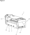
- Figure 4 - is the isometric view of the ice making unit wherein the duct lid is in the closed position.
- Figure 5 - is the cross-sectional view of the ice making unit showing the duct lid.
- Figure 6 - is the front view of the duct lid.
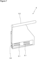
- Figure 7 - is the isometric view of the duct lid.
- Figure 8 - is the isometric view of the ice making unit wherein the duct lid is in the open position.
- Figure 9 - is the isometric cross-sectional view of the ice making unit.
- Figure 10 - is the isometric view of a cooling device comprising the ice making unit.
-
The elements illustrated in the figures are numbered as follows:
- 1. Ice making unit
- 2. Device body
- 2.1. Upper surface
- 2.2. Lower surface
- 2.3. First compartment
- 2.4. Second compartment
- 2.5. Air barrier
- 3. Ice cell
- 3.1. Open surface
- 3.2. Cell body
- 4. Air duct
- 4.1. First end
- 4.2. Second end
- 5. Air blowing unit
- 6. Heating unit
- 7. Additional duct
- 7.1. Additional duct opening
- 7.2. Guide bearing
- 7.3. Opening cover
- 7.4. Cover bracket
- 7.5. Air guiding fin
- 8. Duct lid
- 8.1. Lid slit
- 8.2. Lid opening
- 8.3. Lid shaft
- 9. Storage unit
- P1. Closed position
- P2. Open position
- S. Cooling device
-
The ice making unit (1) of the present invention suitable for the cooling devices (S) comprises a device body (2); a plurality of ice cells (3) which are provided in the device body (2) and which have an open surface (3.1) and a cell body (3.2) for converting water inside into ice; an ice scraper (10) which transfers the ice pieces in the ice cells (3) to an ice storage unit (9); and an air duct (4) with a first end (4.1) connected to the device body (2) and a second end (4.2) connected to an air blowing unit (5) for blowing the cold air.
-
The ice making unit (1) further comprises an air barrier (2.5) which does not allow the air passage between the open surfaces (3.1) and the cell bodies (3.2) and which forms a first compartment (2.3) between the open surfaces (3.1) and an upper surface (2.1) of the device body (2) and a second compartment (2.4) between the cell bodies (3.1) and a lower surface (2.2) of the device body (2); an additional duct (7) with one end opening to the first end (4.1) and which at least one additional duct opening (7.1) opening to the ice storage unit (9); and a duct lid (8) which, in a closed position (P1), closes the first end (4.1) so as not to allow the air passage from the air duct (4) to the first compartment (2.3), so as to partially allow the air passage to the second compartment (2.4) and so as to allow the air passage to the additional duct (7) and which, in an open position (P2), allows the air passage from the air duct (4) to the first compartment (2.3) and the second compartment (2.4) and does not allow the air passage to the additional duct (7).
-
By means of the ice making unit (1) of the present invention, the making of both glass ice pieces and fast ice pieces becomes possible. Here, the duct lid (9) can be shifted to two positions: closed position (P1) and open position (P2). When the duct lid (9) is the closed position (P1), the ice making unit (1) can make glass ice pieces. When the duct lid (9) is the open position (P2), the ice making unit (1) can make fast ice pieces.
-
In order to enable the ice making unit (1) to make fast ice pieces, all of the cold air coming from the air duct (4) must be transferred to the first compartment (2.3) and the second compartment (2.4). The contact of the cold air with the open surfaces (3.1) and cell bodies (3.2) enables the heat transfer, which leads to fast ice making by rapidly turning the water in the ice cell (3) into ice. Some of the cold air delivered to the first compartment (2.3) is discharged through a discharge opening which enables the discharge of the ice pieces in the ice cells (3) provided in the first compartment (2.3). In the cooling device (S) of the present invention, the discharge opening opens to the storage unit (9). Thus, the ice pieces ready in the storage unit (9) are cooled to maintain the ice form.
-
In order to enable the ice making unit (1) to make glass ice pieces, the first compartment (2.3) must be isolated from the cold air coming from the air duct (4). However, only some of the cold air coming from the air duct (4) must be transferred to the second compartment (2.4). Instead of transferring only some of the cold air coming from the air duct (4), the cold air blowing speed of the air blowing unit (5) can be reduced. However, when the cold air blowing speed is reduced, the amount of cold air to be transferred to the storage unit (9) would not be sufficient and the problem of melting ice in the storage unit (9) would occur. In order to prevent this problem, only some of the cold air coming from the air duct (4) to the second compartment (2.4) is transferred without reducing the cold air blowing speed of the air blowing unit (5). A one-way inclined/gradient heat transfer must be provided to the ice cell (3) for making glass ice pieces. Therefore, the air is not allowed to pass to the first compartment (2.3) such that the open surface (3.1) is not cooled. In order to provide inclined/gradient heat transfer, the cold air is partially allowed to pass into the second compartment (2.4). Thus, a cold air flow with reduced speed/flow is formed in the second compartment (2.4). By means of the contact of the cold air with the cell bodies (3.2), the ice cell (3) is cooled by providing inclined/gradient heat transfer through the cell body (3.2). The glass ice pieces are obtained by cooling the ice cell (3) by providing inclined/gradient heat transfer. Since the cold air is not allowed to pass to the first compartment (2.3), the cold air is not discharged through the discharge opening and the storage unit (9) cannot be cooled. In order to cool the storage unit (9), the air is allowed to pass to the additional duct (7) having at least one additional duct opening (7.1) which opens to the ice storage unit (9). Thus, the ice pieces ready in the storage unit (9) are cooled to maintain the ice form.
-
As a result, an ice making unit (1) which can make both fast ice pieces and glass ice pieces is realized.
-
The operation of the ice making unit (1) of the present invention is as follows:
The air blowing unit (5) is for transmitting the cold air to the air duct (4). The cold air in the air duct (4) can be distributed to the first compartment (2.3), the second compartment (2.4) and the additional duct (7) through the first end (4.1). The closed position (P1) and the open position (P2) of the duct lid (8) determine whether the cold air in the air duct (4) is distributed partially and/or fully to the first compartment (2.3), the second compartment (2.4) and the additional duct (7).
Making glass ice pieces: The duct lid (8) in the closed position (P1)
-
In order to enable the ice making unit (1) to make glass ice pieces, the duct lid (8) is shifted to the closed position (P1). The duct lid (8) in the closed position (P1) does not allow the air to pass from the air duct (4) to the first compartment (2.3). Here, the duct lid (8) completely covers/closes the inlet of the first compartment (2.3) opening to the first end (4.1). The duct lid (8) in the closed position (P1) partially allows the air to pass to the second compartment (2.4). Here, the duct lid (8) partially covers/closes the inlet of the second compartment (2.4) opening to the first end (4.1). Moreover, the duct lid (8) in the closed position (P1) allows the air to pass to the additional duct (7). Here, the duct lid (8) does not cover/close the inlet of the additional duct (7) opening to the first end (4.1).
-
Here, since the air passage is not allowed to the first compartment (2.3), the open surfaces (3.1) are not cooled. On the other hand, since the air passage is partially allowed to the second compartment (2.4), the cell bodies (3.2) are cooled at a low speed. Here, the low speed is a cooling rate at a lower level than the case where the air flow is allowed to the second compartment (2.4). In this cooling case, the heat transfer is carried out in an inclined/gradient manner starting from the cell bodies (3.2) to the water in the ice cell (3) and towards the open surfaces (3.1) and the water is enabled to start freezing in an inclined/gradient manner. Here, in order to enable the cold air delivered to the additional duct (7) to be transferred to the storage unit (9), the cold air delivered to the additional duct (7) is discharged through the additional duct opening (7.1). Thus, the ice pieces ready in the storage unit (9) are cooled to maintain the ice form.
Making fast ice pieces: The duct lid (8) in the open position (P2)
-
In order to enable the ice making unit (1) to make fast ice pieces, the duct lid (8) is shifted to the open position (P2). The duct lid (8) in the open position (P2) allows the air passage from the air duct (4) to the first compartment (2.3) and the second compartment (2.4). Here, the duct lid (8) does not cover/close the inlets of the first compartment (2.3) and the second compartment (2.4) opening to the first end (4.1). The duct lid (8) in the open position (P2) does not allow the air passage to the additional duct(7). Here, the duct lid (8) completely covers/closes the inlet of the additional duct (7) opening to the first end (4.1).
-
Here, since the air is allowed to pass to the first compartment (2.3) and the second compartment (2.4), the open surfaces (3.1) and the cell bodies (3.2) start to be cooled at the same time. Thus, the heat transfer is rapidly carried out to the water in the ice cell (3) and the water is enabled to start freezing quickly. Some of the cold air delivered to the first compartment (2.3) through a discharge opening which enables the discharge of the ice pieces in the ice cells (3) provided in the first compartment (2.3) is discharged so as to be transferred to the storage unit (9). Thus, the ice pieces ready in the storage unit (9) are cooled to maintain the ice form.
-
An embodiment of the present invention comprises at least one heating unit which is positioned on the open surfaces (3.1). The heating unit (6) may be configured to heat the open surfaces (3.1) according to a selected time schedule so as to facilitate the heat transfer in an inclined/gradient manner to the water in the ice cell (3) starting from the cell bodies (3.2) towards the open surfaces (3.1). A variation of this embodiment comprises at least one temperature sensor which measures the temperatures of the open surfaces (3.1) and the cell bodies (3.2) or which measures the temperatures of the first compartment (2.3) and the second compartment (2.4). Here, the heating unit (6) is configured to heat the open surfaces (3.1) according to the temperature value comparison of the open surfaces (3.1) - cell bodies (3.2) or the first compartment (2.3) - second compartment (2.4) received from the temperature sensor to facilitate the heat transfer in an inclined/gradient manner to the water in the ice cell (3) starting from the cell bodies (3.2) towards the open surfaces (3.1).
-
An embodiment of the present invention comprises at least one lid slit (8.1) which is provided on one surface of the duct lid (8) closing the inlet of the second compartment (2.4) opening to the first end (4.1) so as to partially allow the air passage from the air duct (4) to the second compartment (2.4) when the duct lid (8) is in the closed position (P1). Here, the part of the surface of the duct lid (8) closing the inlet of the second compartment (2.4) opening to the first end (4.1) other than the lid slit (8.1) prevents some of the cold air coming from the air duct (4) from entering the second compartment (2.4). Some of the cold air coming from the air duct (4) is taken to the second compartment (2.4) through the lid slits (8.1) on the surface of the duct lid (8) closing the inlet of the second compartment (2.4) opening to the first end (4.1). Thus, when the duct lid (8) is in the closed position (P1), the cold air coming from the air duct (4) is partially allowed to pass into the second compartment (2.4).
-
An embodiment of the present invention comprises a lid opening (8.2) which is provided on one surface of the duct lid (8) and which faces the end of the additional duct (7) opening to the first end (4.1) so as to allow the air passage from the air duct (4) to the additional duct (7) when the duct lid (8) is in the closed position (P1).
-
In a variation of this embodiment of the present invention, the surface where the lid slit (8.1) is positioned, in other words, the surface of the duct lid (8) closing the inlet of the second compartment (2.4) opening to the first end (4.1), is inclined so as to direct the air coming from the air duct (4) towards the lid opening (8.2). In this embodiment of the present invention, the gap between the surface where the lid slit (8.1) is positioned and the surface where the lid opening (8.2) is positioned is preferably at an angle of 90° or less. Thus, the cold air coming to the part of the surface of the duct lid (8) closing the inlet of the second compartment (2.4) opening to the first end (4.1) other than the lid slit (8.1) is reflected back and directed towards the lid opening (8.2).
-
An embodiment of the present invention comprises a guide bearing (7.2) which is provided in the additional duct (7); an opening cover (7.3) which can slidably move in the guide bearing (7.2 and which is positioned so as to close the additional duct opening ( 7.1) in the guide bearing (7.2) when the duct lid (8) is in the open position (P2) and so as to open the additional duct opening (7.1) in the guide bearing (7.2) when the duct lid (8) is in the closed position (P1); and a cover bracket (7.4) with one end connected to the duct lid (8) and the other end to the opening cover (7.3), which transfers the movement of the duct lid (8) to the opening cover (7.3).
-
In this embodiment, while the duct lid (8) shifts from the closed position (P1) to the open position (P2) for making fast ice pieces, the duct lid (8) preferentially pulls the cover bracket (7.4). Pulling the cover bracket (7.4) physically applies a pulling force to the opening cover (7.3) to which the same is connected. By means of the pulling force, the opening cover (7.3) is pulled/moved forward by being slid/guided in the guide bearing (7.2) to close the additional duct opening (7.1). By closing the additional duct opening (7.1) in the guide bearing (7.2), the cold air coming from the air duct (4) is prevented from being discharged through the additional duct opening (7.1) during fast ice making. Thus, the ice making speed is increased. In this embodiment, the duct lid (8) preferably pushes the cover bracket (7.4) while the duct lid (8) shifts from the open position (P2) to the closed position (P1) for making glass ice pieces. Pushing the cover bracket (7.4) physically applies a pushing force to the opening cover (7.3) to which the same is connected. By means of the pushing force, the opening cover (7.3) is pushed/moved forward by being slid/guided in the guide bearing (7.2) so as to open the additional duct opening (7.1). By opening the additional duct opening (7.1) in the guide bearing (7.2), the cold air coming from the air duct (4) during glass ice making is discharged through the additional duct opening (7.1). In a variation of this embodiment, the duct lid (8) preferably pushes the cover bracket (7.4) while shifting from the closed position (P1) to the open position (P2) for making fast ice pieces. Pushing the cover bracket (7.4) physically applies a pushing force to the opening cover (7.3) to which the same is connected. By means of the pushing force, the opening cover (7.3) is pushed/moved forward by being slid/guided in the guide bearing (7.2) so as to close the additional duct opening (7.1). By closing the additional duct opening (7.1) in the guide bearing (7.2), the cold air coming from the air duct (4) is prevented from being discharged through the additional duct opening (7.1) during fast ice making. Thus, the ice making speed is increased. In this embodiment, the duct lid (8) preferably pulls the cover bracket (7.4) while the duct lid (8) shifts from the open position (P2) to the closed position (P1) for making glass ice pieces. Pulling the cover bracket (7.4) physically applies a pulling force to the opening cover (7.3) to which the same is connected. By means of the pulling force, the opening cover (7.3) is pulled/moved forward by being slid/guided in the guide bearing (7.2) so as to open the additional duct opening (7.1). By opening the additional duct opening (7.1) in the guide bearing (7.2), the cold air coming from the air duct (4) during glass ice making is discharged through the additional duct opening (7.1).
-
An embodiment of the present invention comprises an air guiding fin (7.5) which is disposed at an outlet of the additional duct opening (7.1) and which ensures that the air coming through the additional duct opening (7.1) is directed to the ice storage unit (9). The air guiding fin (7.5) is preferably disposed on an upper edge of the additional duct opening (7.1) (Figure 9).
-
An embodiment of the present invention comprises an actuator which can move the duct lid (8) to the closed position (P1) and the open position (P2). In a variation of this embodiment of the present invention, the actuator is a rotary actuator. This embodiment comprises a lid shaft (8.3) which is disposed on one side of the duct lid (8), which defines the rotation axis of the duct lid (8) and which connects the duct lid (8) to the actuator. By rotating the rotary actuator in one direction, preferably clockwise, the duct lid (8) shifts from the closed position (P1) to the open position (P2). By rotating the rotary actuator in the other direction, preferably counterclockwise, the duct lid (8) shifts from the open position (P2) to the closed position (P1).
-
In an embodiment of the present invention, the air barrier (2.5) is an integral part of the ice cell (3). Here, the air barrier (2.5) is preferably in the form of extensions disposed around the edges of the open surfaces (3.1) of the ice cell (3). The extensions forming the air barrier (2.5) disposed around the edges of the open surfaces (3.1) join with an inner surface of the device body (2) and provide insulation so as to prevent the air passage between the first compartment (2.3) and the second compartment (2.4).
-
In an embodiment of the present invention, the air blowing unit (5) is a fan.
-
The present invention also relates to a cooling device (S) which comprises any embodiment of the ice making unit (1).