EP4579134A1 - A humidity measurement device and a steam oven comprising the same - Google Patents
A humidity measurement device and a steam oven comprising the same Download PDFInfo
- Publication number
- EP4579134A1 EP4579134A1 EP24208657.7A EP24208657A EP4579134A1 EP 4579134 A1 EP4579134 A1 EP 4579134A1 EP 24208657 A EP24208657 A EP 24208657A EP 4579134 A1 EP4579134 A1 EP 4579134A1
- Authority
- EP
- European Patent Office
- Prior art keywords
- temperature
- cooking chamber
- humidity value
- temperature sensor
- oven
- Prior art date
- Legal status (The legal status is an assumption and is not a legal conclusion. Google has not performed a legal analysis and makes no representation as to the accuracy of the status listed.)
- Pending
Links
Images


Classifications
-
- F—MECHANICAL ENGINEERING; LIGHTING; HEATING; WEAPONS; BLASTING
- F24—HEATING; RANGES; VENTILATING
- F24C—DOMESTIC STOVES OR RANGES ; DETAILS OF DOMESTIC STOVES OR RANGES, OF GENERAL APPLICATION
- F24C7/00—Stoves or ranges heated by electric energy
- F24C7/08—Arrangement or mounting of control or safety devices
- F24C7/082—Arrangement or mounting of control or safety devices on ranges, e.g. control panels, illumination
- F24C7/085—Arrangement or mounting of control or safety devices on ranges, e.g. control panels, illumination on baking ovens
-
- F—MECHANICAL ENGINEERING; LIGHTING; HEATING; WEAPONS; BLASTING
- F24—HEATING; RANGES; VENTILATING
- F24C—DOMESTIC STOVES OR RANGES ; DETAILS OF DOMESTIC STOVES OR RANGES, OF GENERAL APPLICATION
- F24C15/00—Details
- F24C15/32—Arrangements of ducts for hot gases, e.g. in or around baking ovens
- F24C15/322—Arrangements of ducts for hot gases, e.g. in or around baking ovens with forced circulation
- F24C15/327—Arrangements of ducts for hot gases, e.g. in or around baking ovens with forced circulation with air moisturising
Definitions
- an oven comprising a calibration system which continuously measures the temperature in the oven and bring the humidity measurement algorithm to the ideal humidity measurement values by controlling the erroneous measurements caused by changing temperatures due to environmental or physical factors.
- the aim of the present invention is the elimination of all the disadvantages and limitations of the humidity measurement mechanisms in the above-mentioned ovens by realizing an arrangement for humidity measurement which detects levels in a simple and reliable manner based on a different physical principle.
- Another aim of the present invention is the realization of an oven which provides quality cooking by ensuring that the humidity encountered in the ovens, especially in the cooking ovens, where foodstuffs are generally cooked under very high temperature conditions, is regulated at preset levels so as to obtain high performance, regardless of the type and amount of foodstuff.
- the oven of the present invention comprises a user interface which is in communication with the control unit and which has a calibration mode activated by the user at any time during the cooking process to enable the control of the amount of humidity in the cooking chamber.
- the humidity measurement mechanism (5) comprises a sensor block (5.5) which is embedded on the body (3) and which has at least one first temperature sensor (5.1) extending from one end to the cooking chamber (2) and measuring the temperature of the body (3) heated by the air circulation in the cooking chamber (2), a cooling member (5.2) cooled by at least one second fan (5.4) and at least one second temperature sensor (5.3) measuring the temperature of the air blown by the second fan (5.4); and at least one third temperature sensor (5.6) which measures the temperature of the air circulated in the cooking chamber (2).
- a sensor block (5.5) which is embedded on the body (3) and which has at least one first temperature sensor (5.1) extending from one end to the cooking chamber (2) and measuring the temperature of the body (3) heated by the air circulation in the cooking chamber (2), a cooling member (5.2) cooled by at least one second fan (5.4) and at least one second temperature sensor (5.3) measuring the temperature of the air blown by the second fan (5.4); and at least one third temperature sensor (5.6) which measures the temperature of the air circulated in the cooking chamber (2)
- the cooking temperature (T1) of the foodstuffs in the cooking chamber (2) as well as the temperature (T2) of the cooking vessel are measured by the third temperature sensor (5.6).
- the temperature (T3) of the hot air circulating in the cooking chamber (2) is also measured by means of the first temperature sensor (5.1) which is positioned at the point of contact of the sensor block (5.5) with the cooking chamber (3) as embedded in the body (3) and extending towards the cooking chamber (2).
- the temperature of the body (3) is particularly subject to direct contact with the hot air circulating in the cooking chamber (2).
- the relationship between the said calculated heat transfer coefficient and the instantaneous oven interior humidity value is expressed empirically.
- the humidity of the cooking chamber (2) can be measured by generating an empirical expression with the said three parameters (T1 or T2, T3 and T4).
- the oven (1) comprises a user interface (7) which is communication with the control unit (6) and which has a calibration mode (7.1) activated by user selection to enable the control of the amount of humidity in the cooking chamber (2) at any time during the cooking process.
- the oven (1) comprises a user interface (7) which has a calibration mode (7.1) activated by user selection to control the amount of humidity in the cooking zone (2); and a control unit (6) which is in communication with the user interface (7) and at least one temperature sensor (5.1, 5.3, 5.6) in the humidity measurement mechanism (5), which can be positioned at any point on the body, which compares a predetermined ideal reference humidity value (RH1) with the humidity value (RH2) calculated instantly according to the data received from the said temperature sensors (5.1, 5.3, 5.5), and which, if the humidity value (RH2) resulting from the said calculation is different from the said reference humidity value (RH1), changes the predefined ⁇ , ⁇ and ⁇ coefficients for the said T1 or T2, T3 and T4 temperature values, respectively, to approach the said reference value (RH1).
- a predetermined ideal reference humidity value (RH1) with the humidity value (RH2) calculated instantly according to the data received from the said temperature sensors (5.1, 5.3, 5.5
- RH1 predefined
- a predefined amount of water for example 1 liter, is placed in the cooking chamber (2).
- the temperature value reached by the oven (1) during the cooking process and the ideal reference humidity value (RH1) formed in the oven (1) are defined as a predetermined value in the control unit (6).
- the user activates the calibration mode (7.1), and in the calibration program, when the reference humidity value (RH1) and the instantaneous humidity value (RH2) measured in the oven (1) differ according to the humidity level of the water evaporated at a constant temperature during the cooking process, the control unit (6) changes the predefined ⁇ , ⁇ and ⁇ coefficients of the T3, T4 and T1 or T2 temperature values measured by the temperature sensors (5.1, 5.3, 5.5), respectively, and brings the predefined reference humidity value (RH1) and the instantaneous humidity value (RH2) measured in the oven (1) closer to each other.
Landscapes
- Engineering & Computer Science (AREA)
- Chemical & Material Sciences (AREA)
- Combustion & Propulsion (AREA)
- Mechanical Engineering (AREA)
- General Engineering & Computer Science (AREA)
- Electric Ovens (AREA)
Abstract
The present invention relates to an oven (1) comprising a cooking chamber (2); a body (3) which surrounds the cooking chamber (2) and a first fan (4) which is positioned in the cooking chamber (2); by a humidity measurement mechanism (5) having a sensor block (5.5) which is positioned on the body (3) and which has at least one first temperature sensor (5.1) for detecting the body (3) temperature, a cooling member (5.2) cooled by at least one second fan (5.4) positioned thereon and at least one second temperature sensor (5.3) measuring the temperature of the area of effect of the cooling member (5.2) on the body (3) and at least one third temperature sensor (5.6) which is positioned in the cooking chamber (2) and which measures the temperature of the air circulated by the first fan (4) in the cooking chamber (2); and a control unit (6) which is in communication with the humidity measurement mechanism (5), which compares, during the cooking process, an ideal reference humidity value (RH1), a predetermined value corresponding to the dew point of the water vapor in the air in the cooking chamber (2) with the instantaneous humidity value (RH2) calculated based on the temperature values measured simultaneously by the first, second and third temperature sensors (5.1, 5.3, 5.6), and which is configured to approximate the measured instantaneous humidity value (RH2) to the ideal reference humidity value (RH1) if the instantaneous humidity value (RH2) resulting from said calculation differs from said reference humidity value (RH1).
Description
- The present invention relates to a steam oven comprising a humidity measurement device which adjusts the humidity level during the cooking processes.
- Ovens with humidification function for the cooking environment comprise a humidification device which injects moisture into the cooking chamber. The ovens with humidification function better preserve the organoleptic properties of foodstuffs, while keeping the foodstuffs in its own juices, thus ensuring that the foodstuffs are cooked so as to be soft and delicious. Moreover, the weight loss caused by liquid leaks of foodstuffs, which is an important issue during cooking, is eliminated.
- Such steam ovens comprise thermostatic control systems suitable for regulating the foodstuff cooking temperature, which are associated with temperature selector means, which must be adjusted to the desired temperature value according to the type and quantity of the foodstuff to be cooked before starting any cooking process.
- The steam ovens with thermostatic temperature control systems are generally operated to maintain the cooking temperature in the cooking chamber within predefined limits by energizing both the heat generator and the steam generator and by cutting off the supplied energy. The said ovens are also designed to cook with steam and a fan which moves the air. Thus, the flow of the air circulating in the cooking chamber is accordingly changed.
- However, the said steam ovens do not have any system used to regulate the humidity of the air in the cooking chamber. The amount of humidity to be delivered into the oven, together with the temperature, is a factor which definitely affects the quality of the cooking results and the taste and flavor of the cooked foodstuffs. Because the amount of humidity to be delivered into the oven is adjusted according to parameters such as the cooking temperature, the type and amount of the foodstuff to be cooked, and the air exchange rate in the cooking chamber. The ovens which do not contain a device to control the amount of humidity in the oven provide relatively good performance capabilities, but do not provide the best cooking results.
- One of the most important problems encountered in the state of the art is that some of the parameters of ovens tested during the production change over time according to the geographical locations where the ovens are used or the shape of the furniture wherein the ovens are installed. For example, in case sufficient cold and clean air cannot be supplied to cool the sensor due to the shape of the furniture wherein the oven is installed (such as zero assembly or gapless placement), the margin of error in the measurements taken by the sensors increases or starts to change.
- Similarly, it is observed that the measurements taken by the sensor block are corrupted in case the ovens operating in different climate conditions, such as environments with extreme air temperatures, overheat or overcool.
- Another reason for incorrect measurement is the occurrence of sensor measurement errors due to the shift in the temperature conditions of the cooking zone over time caused by the sealing problem occurring on the oven door or in different parts of the oven or in different components. As a result of these incorrect measurements, humidity is measured incorrectly due to the temperature values measured from the cooking zone and oven body.
- Due to the problems experienced in the state of the art, there is a need for an oven comprising a calibration system which continuously measures the temperature in the oven and bring the humidity measurement algorithm to the ideal humidity measurement values by controlling the erroneous measurements caused by changing temperatures due to environmental or physical factors.
- The aim of the present invention is the elimination of all the disadvantages and limitations of the humidity measurement mechanisms in the above-mentioned ovens by realizing an arrangement for humidity measurement which detects levels in a simple and reliable manner based on a different physical principle. Another aim of the present invention is the realization of an oven which provides quality cooking by ensuring that the humidity encountered in the ovens, especially in the cooking ovens, where foodstuffs are generally cooked under very high temperature conditions, is regulated at preset levels so as to obtain high performance, regardless of the type and amount of foodstuff.
- Another aim of the present invention is the realization of an oven which can continuously control the amount of steam in the steam ovens and calibrate the humidity level, which is one of the parameters directly affecting homogeneous and effective cooking, under different conditions.
- Another aim of the present invention is the realization of an oven with improved cooking performance where the steam can be fully controlled with continuous and high precision humidity measurement instead of instantaneous measurement at high temperatures.
- In order to attain the above aims, the oven of the present invention comprises a cooking chamber; a body which surrounds the cooking chamber; and at least one first fan which is positioned in the cooking chamber. The oven of the present invention comprises a humidity measurement mechanism having a sensor block which is positioned on the body and which has at least one first temperature sensor for detecting the body temperature, a cooling member cooled by at least one second fan positioned thereon and at least one second temperature sensor measuring the temperature of the area of effect of the cooling member on the body, and at least one third temperature sensor which is positioned in the cooking chamber and which measures the temperature of the air circulated by the first fan in the cooking chamber; and a control unit which is in communication with the humidity measurement mechanism, which compares, during the cooking process, an ideal reference humidity value (RH1), a predetermined value corresponding to the dew point of the water vapor in the air in the cooking chamber with the instantaneous humidity value (RH2) calculated based on the temperature values measured simultaneously by the first, second and third temperature sensors, and which is configured to bring the measured instantaneous humidity value (RH2) closer to the ideal reference humidity value (RH1) if the instantaneous humidity value (RH2) resulting from the said calculation differs from the said reference humidity value (RH1).
- In order to attain the above aims, the oven of the present invention comprises a control unit which calculates the instantaneous humidity value (RH2) with the β coefficient assigned to the T3 temperature taken from the first temperature sensor, the γ coefficient assigned to the T4 temperature taken from the second temperature sensor and the α coefficient assigned to the T1 temperature taken from the third temperature sensor and which is configured to bring the instantaneous humidity value (RH2) closer to the ideal reference humidity value (RH1) by changing the α, β and γ coefficients if the instantaneous humidity value (RH2) deviates from the ideal reference humidity value (RH1).
- In order to attain the above aims, the oven of the present invention comprises the sensor block which is embedded on the body and which has at least one first temperature sensor extending from one end to the cooking chamber and measuring the temperature of the body heated by the air circulation in the cooking chamber.
- In order to attain the above aims, the oven of the present invention comprises a user interface which is in communication with the control unit and which has a calibration mode activated by the user at any time during the cooking process to enable the control of the amount of humidity in the cooking chamber.
- The said figures are:
-
Figure 1 : is the front perspective view of an oven. -
Figure 2 : is the top perspective view of an oven and a sensor block. -
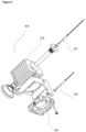
Figure 3 : is the exploded view of a sensor block. - The following numerals are referred to in the description of the present invention:
- 1. Oven
- 2. Cooking chamber
- 3. Body
- 4. First fan
- 5. Humidity measurement mechanism
- 5.1 First temperature sensor
- 5.2 Cooling member
- 5.3 Second temperature sensor
- 5.4 Second fan
- 5.5 Sensor block
- 5.6 Third temperature sensor
- 6. Control unit
- 7. User interface
7.1 Calibration mode - The oven of the present invention has the feature of circulating hot air or steam alone, and/or hot air/steam together and/or microwave alone, and/or microwave hot air/steam together, and comprises a cooking chamber (2) which is defined by side walls, a rear wall, a top wall, a bottom wall and a front wall and wherein the foodstuff to be cooked is placed; a body (3) which surrounds the cooking chamber (2); at least one first fan (4) which is positioned on the body; a humidity measurement mechanism (5) which measures the humidity level of the cooking chamber (2); and a control unit (6) which is in communication with the humidity measurement mechanism (5).
- In an embodiment of the present invention, the humidity measurement mechanism (5) comprises a sensor block (5.5) which is embedded on the body (3) and which has at least one first temperature sensor (5.1) extending from one end to the cooking chamber (2) and measuring the temperature of the body (3) heated by the air circulation in the cooking chamber (2), a cooling member (5.2) cooled by at least one second fan (5.4) and at least one second temperature sensor (5.3) measuring the temperature of the air blown by the second fan (5.4); and at least one third temperature sensor (5.6) which measures the temperature of the air circulated in the cooking chamber (2). Thus, while one end of the sensor block (5.5) is continuously heated in the cooking chamber (2), the other end thereof is continuously cooled by the second fan (5.4). Therefore, a heat transfer from hot to cold takes place on the sensor block (5.5) and the said heat transfer is numerically calculated by the first temperature sensor (5.1) and the second temperature sensor (5.3) in the sensor block (5.5) and the third temperature sensor (5.6) used for temperature adjustment in the cooking chamber (2).
- Thus, by means of the described arrangement of the temperature sensors (5.1, 5.3, 5.6), the cooking temperature (T1) of the foodstuffs in the cooking chamber (2) as well as the temperature (T2) of the cooking vessel are measured by the third temperature sensor (5.6). The temperature (T3) of the hot air circulating in the cooking chamber (2) is also measured by means of the first temperature sensor (5.1) which is positioned at the point of contact of the sensor block (5.5) with the cooking chamber (3) as embedded in the body (3) and extending towards the cooking chamber (2). Here, the temperature of the body (3) is particularly subject to direct contact with the hot air circulating in the cooking chamber (2). The cooling member (5.2) which is equipped with a plurality of separate fins arranged so as to be hit by the air flow generated by the second fan (5.4) positioned on the body (3), slowly cools the sensor block (5.5) and the temperature difference in the sensor block (5.5) is detected by at least one second temperature sensor (5.3) measuring the temperature (T4) of the area where the sensor block (5.5) comes into contact with the cooling member (5.2). As can be understood, while one end of the sensor block (5.5) is continuously heated in the body (3), the other end thereof is continuously cooled by the second fan (5.4). Therefore, a heat transfer from hot to cold occurs on the sensor block (5.5) and this heat transfer is calculated numerically with the T3 value taken by the first temperature sensor (5.1) in the sensor block (5.5), the T4 value taken by the second temperature sensor (5.3) and the T1 or T2 values taken by the third temperature sensor (5.6) used in the temperature adjustment in the cooking chamber (2). In the said numerical calculation, the said T1 or T2, T3 and T4 temperature values have the predefined α, β and γ coefficients, respectively.
- The relationship between the said calculated heat transfer coefficient and the instantaneous oven interior humidity value is expressed empirically. The humidity of the cooking chamber (2) can be measured by generating an empirical expression with the said three parameters (T1 or T2, T3 and T4).
- The instantaneous oven interior humidity value is expressed as F(RH2) = α*T1 + β*T3 + γ*T4. The parameters α, β, and γ in this equation are predefined in the oven and are controlled adaptively by the control unit (6).
- In an embodiment of the present invention, the oven (1) comprises a user interface (7) which is communication with the control unit (6) and which has a calibration mode (7.1) activated by user selection to enable the control of the amount of humidity in the cooking chamber (2) at any time during the cooking process.
- In an embodiment of the present invention, the oven (1) comprises a user interface (7) which has a calibration mode (7.1) activated by user selection to control the amount of humidity in the cooking zone (2); and a control unit (6) which is in communication with the user interface (7) and at least one temperature sensor (5.1, 5.3, 5.6) in the humidity measurement mechanism (5), which can be positioned at any point on the body, which compares a predetermined ideal reference humidity value (RH1) with the humidity value (RH2) calculated instantly according to the data received from the said temperature sensors (5.1, 5.3, 5.5), and which, if the humidity value (RH2) resulting from the said calculation is different from the said reference humidity value (RH1), changes the predefined α, β and γ coefficients for the said T1 or T2, T3 and T4 temperature values, respectively, to approach the said reference value (RH1).
- In an embodiment of the present invention, a predefined amount of water, for example 1 liter, is placed in the cooking chamber (2). The temperature value reached by the oven (1) during the cooking process and the ideal reference humidity value (RH1) formed in the oven (1) are defined as a predetermined value in the control unit (6). The user activates the calibration mode (7.1), and in the calibration program, when the reference humidity value (RH1) and the instantaneous humidity value (RH2) measured in the oven (1) differ according to the humidity level of the water evaporated at a constant temperature during the cooking process, the control unit (6) changes the predefined β, γ and α coefficients of the T3, T4 and T1 or T2 temperature values measured by the temperature sensors (5.1, 5.3, 5.5), respectively, and brings the predefined reference humidity value (RH1) and the instantaneous humidity value (RH2) measured in the oven (1) closer to each other.
Claims (4)
- An oven (1) comprising a cooking chamber (2); a body (3) which surrounds the cooking chamber (2) and at least one first fan (4) positioned in the cooking chamber (2), characterized by a humidity measurement mechanism (5) having a sensor block (5.5) positioned on the body (3) and having at least one first temperature sensor (5.1) for detecting the body (3) temperature, a cooling member (5.2) cooled by at least one second fan (5.4) positioned thereon and at least one second temperature sensor (5.3) measuring the temperature of the area of effect of the cooling member (5.2) on the body (3) and at least one third temperature sensor (5.6) positioned in the cooking chamber (2) and measuring the temperature of the air circulated by the first fan (4) in the cooking chamber (2); and a control unit (6) communicating with the humidity measurement mechanism (5), comparing, during the cooking process, an ideal reference humidity value (RH1), a predetermined value corresponding to the dew point of the water vapor in the air in the cooking chamber (2) with the instantaneous humidity value (RH2) calculated based on the temperature values measured simultaneously by the first, second and third temperature sensors (5.1, 5.3, 5.6), and configured to approximate the measured instantaneous humidity value (RH2) to the ideal reference humidity value (RH1) if the instantaneous humidity value (RH2) resulting from said calculation differs from said reference humidity value (RH1).
- An oven (1) as in Claim 1, characterized by a control unit calculating the instantaneous humidity value (RH2) with the β coefficient assigned to the T3 temperature taken from the first temperature sensor (5.1), the γ coefficient assigned to the T4 temperature taken from the second temperature sensor (5.3) and the α coefficient assigned to the T1 temperature taken from the third temperature sensor (5.6) and configured to bring the instantaneous humidity value (RH2) closer to the ideal reference humidity value (RH1) by changing the α, β and γ coefficients if the instantaneous humidity value (RH2) deviates from the ideal reference humidity value (RH1).
- An oven (1) as in Claim 1 or 2, characterized by the sensor block (5.5) embedded on the body (3) and having at least one first temperature sensor (5.1) extending from one end to the cooking chamber (2) and measuring the temperature of the body (3) heated by the air circulation in the cooking chamber (2).
- An oven (1) as in any one of the above claims, characterized by a user interface (7) communicating with the control unit (6) and having a calibration mode (7.1) activated by user selection to enable the control of the amount of humidity in the cooking chamber (2) at any time during the cooking process.
Applications Claiming Priority (1)
| Application Number | Priority Date | Filing Date | Title |
|---|---|---|---|
| TR202318445 | 2023-12-26 |
Publications (1)
| Publication Number | Publication Date |
|---|---|
| EP4579134A1 true EP4579134A1 (en) | 2025-07-02 |
Family
ID=93284553
Family Applications (1)
| Application Number | Title | Priority Date | Filing Date |
|---|---|---|---|
| EP24208657.7A Pending EP4579134A1 (en) | 2023-12-26 | 2024-10-24 | A humidity measurement device and a steam oven comprising the same |
Country Status (1)
| Country | Link |
|---|---|
| EP (1) | EP4579134A1 (en) |
Citations (4)
| Publication number | Priority date | Publication date | Assignee | Title |
|---|---|---|---|---|
| US5272963A (en) * | 1992-04-29 | 1993-12-28 | Zanussi Grandi Impianti S.P.A. | Arrangement for measuring moisture in ovens, in particular food cooking ovens |
| EP1936279A1 (en) * | 2006-12-11 | 2008-06-25 | Miele & Cie. KG | Method and device for evaluating the amount of vapour over time emitted by the food during cooking in an oven cavity |
| GB2567076A (en) * | 2016-11-28 | 2019-04-03 | Cambridge Sensor Innovation Ltd | Humidity determination |
| CN116725379A (en) * | 2023-07-26 | 2023-09-12 | 宁波方太厨具有限公司 | Cooking equipment, control method thereof and humidity detection device |
-
2024
- 2024-10-24 EP EP24208657.7A patent/EP4579134A1/en active Pending
Patent Citations (4)
| Publication number | Priority date | Publication date | Assignee | Title |
|---|---|---|---|---|
| US5272963A (en) * | 1992-04-29 | 1993-12-28 | Zanussi Grandi Impianti S.P.A. | Arrangement for measuring moisture in ovens, in particular food cooking ovens |
| EP1936279A1 (en) * | 2006-12-11 | 2008-06-25 | Miele & Cie. KG | Method and device for evaluating the amount of vapour over time emitted by the food during cooking in an oven cavity |
| GB2567076A (en) * | 2016-11-28 | 2019-04-03 | Cambridge Sensor Innovation Ltd | Humidity determination |
| CN116725379A (en) * | 2023-07-26 | 2023-09-12 | 宁波方太厨具有限公司 | Cooking equipment, control method thereof and humidity detection device |
Similar Documents
| Publication | Publication Date | Title |
|---|---|---|
| US4841111A (en) | Microwave oven with improved defrosting mode | |
| US10599168B2 (en) | Food service oven with multipoint temperature monitoring | |
| US7750271B2 (en) | Systems and methods for controlling oven cooking | |
| US4962299A (en) | Method and apparatus for the thermal control of a heating device | |
| US11940332B2 (en) | Wet bulb temperature sensor system and method for direct measurement of wet bulb temperature in an oven | |
| EP2938238B1 (en) | Holding cabinets, methods for controlling environmental conditions in holding cabinets, and computer-readable media storing instructions for implementing such methods | |
| US20120318252A1 (en) | Variable speed steam cooker | |
| CN102261633B (en) | There is the cooking appliance of steam generating function | |
| JP5496168B2 (en) | Cooker | |
| US4154855A (en) | Method of cooking foods in a microwave oven | |
| ES3001009T3 (en) | Cooking utensil, cooking system and operating procedure | |
| CN110960080B (en) | Cooking method for rice cooker and cooking appliance | |
| KR100812177B1 (en) | Thermostat and control method of electric rice cooker | |
| US5780818A (en) | Method of automatically cooking food with forced hot air | |
| US12383097B2 (en) | Temperature controlled accessory for countertop cooking system | |
| WO2024144508A1 (en) | A humidity measurement device and a steam oven comprising the same | |
| JP4258417B2 (en) | Electric jar rice cooker | |
| GB2404293A (en) | Electric heater for heating a liquid in two phases | |
| EP4579155A1 (en) | A cooling device | |
| EP4682429A1 (en) | A cooking device comprising a camera | |
| WO2021024137A1 (en) | Apparatus for rising dough | |
| US20250264222A1 (en) | Adjusting a cooking cycle according to thermal attributes of cookware items | |
| CN112128807B (en) | Cooker with precise temperature sensing function and control method thereof | |
| TWI711792B (en) | Heating conditioner | |
| CA2537625A1 (en) | Systems and methods for controlling oven cooking |
Legal Events
| Date | Code | Title | Description |
|---|---|---|---|
| PUAI | Public reference made under article 153(3) epc to a published international application that has entered the european phase |
Free format text: ORIGINAL CODE: 0009012 |
|
| STAA | Information on the status of an ep patent application or granted ep patent |
Free format text: STATUS: REQUEST FOR EXAMINATION WAS MADE |
|
| 17P | Request for examination filed |
Effective date: 20241024 |
|
| AK | Designated contracting states |
Kind code of ref document: A1 Designated state(s): AL AT BE BG CH CY CZ DE DK EE ES FI FR GB GR HR HU IE IS IT LI LT LU LV MC ME MK MT NL NO PL PT RO RS SE SI SK SM TR |
|
| STAA | Information on the status of an ep patent application or granted ep patent |
Free format text: STATUS: THE APPLICATION IS DEEMED TO BE WITHDRAWN |