EP4579126A1 - Display unit and household appliance having display unit - Google Patents
Display unit and household appliance having display unit Download PDFInfo
- Publication number
- EP4579126A1 EP4579126A1 EP24217418.3A EP24217418A EP4579126A1 EP 4579126 A1 EP4579126 A1 EP 4579126A1 EP 24217418 A EP24217418 A EP 24217418A EP 4579126 A1 EP4579126 A1 EP 4579126A1
- Authority
- EP
- European Patent Office
- Prior art keywords
- light
- display panel
- display unit
- guide member
- light guide
- Prior art date
- Legal status (The legal status is an assumption and is not a legal conclusion. Google has not performed a legal analysis and makes no representation as to the accuracy of the status listed.)
- Pending
Links
Images




Classifications
-
- G—PHYSICS
- G02—OPTICS
- G02B—OPTICAL ELEMENTS, SYSTEMS OR APPARATUS
- G02B6/00—Light guides; Structural details of arrangements comprising light guides and other optical elements, e.g. couplings
- G02B6/0001—Light guides; Structural details of arrangements comprising light guides and other optical elements, e.g. couplings specially adapted for lighting devices or systems
- G02B6/0011—Light guides; Structural details of arrangements comprising light guides and other optical elements, e.g. couplings specially adapted for lighting devices or systems the light guides being planar or of plate-like form
- G02B6/0081—Mechanical or electrical aspects of the light guide and light source in the lighting device peculiar to the adaptation to planar light guides, e.g. concerning packaging
- G02B6/0086—Positioning aspects
- G02B6/0091—Positioning aspects of the light source relative to the light guide
-
- G—PHYSICS
- G02—OPTICS
- G02B—OPTICAL ELEMENTS, SYSTEMS OR APPARATUS
- G02B6/00—Light guides; Structural details of arrangements comprising light guides and other optical elements, e.g. couplings
- G02B6/0001—Light guides; Structural details of arrangements comprising light guides and other optical elements, e.g. couplings specially adapted for lighting devices or systems
- G02B6/0011—Light guides; Structural details of arrangements comprising light guides and other optical elements, e.g. couplings specially adapted for lighting devices or systems the light guides being planar or of plate-like form
- G02B6/0081—Mechanical or electrical aspects of the light guide and light source in the lighting device peculiar to the adaptation to planar light guides, e.g. concerning packaging
- G02B6/0086—Positioning aspects
- G02B6/009—Positioning aspects of the light source in the package
-
- G—PHYSICS
- G09—EDUCATION; CRYPTOGRAPHY; DISPLAY; ADVERTISING; SEALS
- G09F—DISPLAYING; ADVERTISING; SIGNS; LABELS OR NAME-PLATES; SEALS
- G09F13/00—Illuminated signs; Luminous advertising
- G09F13/04—Signs, boards or panels, illuminated from behind the insignia
- G09F13/0418—Constructional details
-
- A—HUMAN NECESSITIES
- A47—FURNITURE; DOMESTIC ARTICLES OR APPLIANCES; COFFEE MILLS; SPICE MILLS; SUCTION CLEANERS IN GENERAL
- A47L—DOMESTIC WASHING OR CLEANING; SUCTION CLEANERS IN GENERAL
- A47L15/00—Washing or rinsing machines for crockery or tableware
- A47L15/42—Details
- A47L15/4293—Arrangements for programme selection, e.g. control panels; Indication of the selected programme, programme progress or other parameters of the programme, e.g. by using display panels
-
- F—MECHANICAL ENGINEERING; LIGHTING; HEATING; WEAPONS; BLASTING
- F25—REFRIGERATION OR COOLING; COMBINED HEATING AND REFRIGERATION SYSTEMS; HEAT PUMP SYSTEMS; MANUFACTURE OR STORAGE OF ICE; LIQUEFACTION SOLIDIFICATION OF GASES
- F25D—REFRIGERATORS; COLD ROOMS; ICE-BOXES; COOLING OR FREEZING APPARATUS NOT OTHERWISE PROVIDED FOR
- F25D29/00—Arrangement or mounting of control or safety devices
- F25D29/005—Mounting of control devices
-
- G—PHYSICS
- G02—OPTICS
- G02B—OPTICAL ELEMENTS, SYSTEMS OR APPARATUS
- G02B6/00—Light guides; Structural details of arrangements comprising light guides and other optical elements, e.g. couplings
- G02B6/0001—Light guides; Structural details of arrangements comprising light guides and other optical elements, e.g. couplings specially adapted for lighting devices or systems
- G02B6/0011—Light guides; Structural details of arrangements comprising light guides and other optical elements, e.g. couplings specially adapted for lighting devices or systems the light guides being planar or of plate-like form
- G02B6/0081—Mechanical or electrical aspects of the light guide and light source in the lighting device peculiar to the adaptation to planar light guides, e.g. concerning packaging
- G02B6/0095—Light guides as housings, housing portions, shelves, doors, tiles, windows, or the like
-
- G—PHYSICS
- G02—OPTICS
- G02F—OPTICAL DEVICES OR ARRANGEMENTS FOR THE CONTROL OF LIGHT BY MODIFICATION OF THE OPTICAL PROPERTIES OF THE MEDIA OF THE ELEMENTS INVOLVED THEREIN; NON-LINEAR OPTICS; FREQUENCY-CHANGING OF LIGHT; OPTICAL LOGIC ELEMENTS; OPTICAL ANALOGUE/DIGITAL CONVERTERS
- G02F1/00—Devices or arrangements for the control of the intensity, colour, phase, polarisation or direction of light arriving from an independent light source, e.g. switching, gating or modulating; Non-linear optics
- G02F1/01—Devices or arrangements for the control of the intensity, colour, phase, polarisation or direction of light arriving from an independent light source, e.g. switching, gating or modulating; Non-linear optics for the control of the intensity, phase, polarisation or colour
- G02F1/13—Devices or arrangements for the control of the intensity, colour, phase, polarisation or direction of light arriving from an independent light source, e.g. switching, gating or modulating; Non-linear optics for the control of the intensity, phase, polarisation or colour based on liquid crystals, e.g. single liquid crystal display cells
- G02F1/133—Constructional arrangements; Operation of liquid crystal cells; Circuit arrangements
- G02F1/1333—Constructional arrangements; Manufacturing methods
- G02F1/1335—Structural association of cells with optical devices, e.g. polarisers or reflectors
- G02F1/1336—Illuminating devices
- G02F1/133615—Edge-illuminating devices, i.e. illuminating from the side
-
- G—PHYSICS
- G09—EDUCATION; CRYPTOGRAPHY; DISPLAY; ADVERTISING; SEALS
- G09F—DISPLAYING; ADVERTISING; SIGNS; LABELS OR NAME-PLATES; SEALS
- G09F23/00—Advertising on or in specific articles, e.g. ashtrays, letter-boxes
- G09F23/0058—Advertising on or in specific articles, e.g. ashtrays, letter-boxes on electrical household appliances, e.g. on a dishwasher, a washing machine or a refrigerator
Definitions
- Embodiments of the present invention relate to a display unit and a household appliance having the display unit.
- a household appliance usually has a display unit for a user to obtain information about the household appliance and/or to receive an input instruction of the user for the household appliance.
- the display unit usually has a backlight to illuminate a display panel.
- a range of an area on the display panel that can be illuminated is limited by an arrangement range of a backlight apparatus.
- An aspect of the embodiments of the present invention relates to a display unit configured for a household appliance.
- the display unit includes: a display panel; a printed circuit board, including at least one first light-emitting element configured to illuminate the display panel; and a light guide member, including a light incident surface facing the first light-emitting element and a light outgoing surface facing a rear surface of the display panel, where the light outgoing surface is closer to an edge of the display panel than the light incident surface in a direction parallel to the printed circuit board.
- the printed circuit board 53 is located on a rear side of the bracket 56 facing away from the display panel 54.
- the touch film 55 is connected to the printed circuit board 53 through a connecting portion 552 spanning the bracket 56.
- a slight spacing (for example, not greater than 1 millimeter) is maintained between the illuminated area 546 and the outline 541, and the spacing between the illuminated area 546 and the outline 541 is not visible to naked eyes. The user sees that the illuminated area 546 extends inward by a predetermined distance from an outermost edge of the display panel 54.
- the light guide member 57 includes a light incident surface 571 facing the first light-emitting element 531 and a light outgoing surface 572 facing the rear surface 548 of the display panel 54.
- the light outgoing surface 572 is closer to an edge of the display panel 54 than the light incident surface 571, and closer to the outline 541 of the display panel 54 in particular.
- the light outgoing surface 572 may be in a shape adapted to a shape of the display panel 54.
- the light outgoing surface 572 is a flat surface.
- the outline 541 extends in a transverse direction X of the display panel 54. Therefore, a spacing exists between the light outgoing surface 572 and the first light-emitting element 531, and between the light incident surface 571 and the first light-emitting element 531 in a height direction Y of the display panel 54. It should be understood that, if the outline extends in the height direction of the display panel, a spacing may exist between the light outgoing surface 572 and the first light-emitting element 531, and between the light incident surface 571 and the first light-emitting element 531 in the transverse direction X of the display panel 54.
- FIG. 1 schematically shows the illuminated area 546 of the display panel 54 illuminated by the light transmitted from the light guide member 57.
- the illuminated area 546 covers the outline 541 extending along a lower edge of the display panel 54.
- the display panel 54 includes the end surface 547 connected to the front surface 545 and the rear surface 548 of the display panel 54. In a direction Z perpendicular to the display panel 54, a projection of the end surface 547 is located within the light outgoing surface 572.
- the part of the light guide member 57 exposed outside the display unit 5 is located between the light outgoing surface 572 and the light incident surface 571.
- the light guide member 57 may be arranged so that light is not transmitted out from the part exposed to the outer side of the display unit 5.
- the peripheral surface 573 is exposed to the outer side of the display unit 5, to be touchable from the outer side of the display unit 5.
- the end surface 547 and the light guide member 57 may be flush.
- the light guide member 573 includes an inclined light guide portion 574 located between the light incident surface 571 and the light outgoing surface 572, so that a transmission path of light in the light guide member has a distance in the direction parallel to the display panel 54. In this way, the light emitted by the first light-emitting element 531 can illuminate the edge area of the display panel 54.
- the display unit 5 includes a peripheral wall 565 located between the printed circuit board 53 and the display panel 54 in the direction perpendicular to the display panel 54.
- the peripheral wall 565 has a window 566, and the light guide member 57 is located in the window 566. Therefore, the light guide member 57 is exposed outside the display unit 5.
- the window 566 may be closed by the light guide member 57, as shown in FIG. 3 .
- the light outgoing surface 572 overlaps with the window 566. Therefore, the illuminated area 546 illuminated by the light outgoing surface 572 overlaps with the window 566.
- the peripheral surface 573 located in the window 566 and exposed outside the display unit 5 may be a flat surface. Therefore, after the window 566 is closed, it is possible that the peripheral surface 573 and the peripheral wall 565 may be substantially located in the same plane and be substantially flush.
- the printed circuit board 53 may be supported on the bracket 56.
- the peripheral wall 565 is located in the bracket 56, so that the bracket 56 forms a part of the outer peripheral surface of the display unit 54.
- the bracket 56 includes a receiving slot 567 configured to receive the light guide member 57.
- the receiving slot 567 communicates the chamber 59 with a front side and a peripheral side of the bracket 56. In this way, the receiving slot 567 is open on a front side facing the display panel 54 and on a peripheral side. In an embodiment, the receiving slot 567 is open downward.
- a front end of the light guide member 57 extends out of the receiving slot 567, and is located in a space 568 formed between the display panel 54 and the bracket 56.
- the light outgoing surface 572 is located in the space 568 and faces the rear surface 548 of the display panel 54.
- the peripheral surface 573 is exposed outside of the display unit 5 at the space 568.
- the light guide member 57 extends along an entire width of the display unit 5, so that the receiving slot 567 also extends along the entire width of the display unit 5. Two ends of the light guide member 57 may be exposed on two sides of the display unit 5 in a transverse direction.
- the light guide member 57 is adapted to be inserted into the receiving slot 567 from the front side of the bracket 56. As shown in FIG. 2, FIG. 3 , and FIG. 6 , the light guide member 57 is clamped on the bracket 57.
- the light guide member 57 includes a plurality of hook portions 575 protruding upward. After the light guide member 57 is inserted into the receiving slot 567 from the front side of the bracket 56, the hook portions 575 are hooked with a free end of an elastic arm 569 of the bracket 57, thereby preventing the light guide member 57 from exiting the receiving slot 567.
- a rear end of the elastic arm 569 is the free end.
- the elastic arm 569 deforms upward under an action of a top end of the hook portion 575, to allow the hook portion 575 to enter the light guide member 57 to move to the light incident surface 571, to become close to the first light-emitting element 531.
- movement of the light guide member 57 in a front-rear direction is limited.
- a guide structure configured to locate the light guide member 57 and guide insertion of the light guide member 57 into the receiving slot 567 is arranged between the bracket 56 and the light guide member 57.
- the guide structure may include a plurality of guide blocks 576 protruding upward from the light guide member 57, and the light guide member 57 has a guide groove 5691 adapted to receive the guide block 576.
- the bracket 56 includes an inclined wall 5692 defining a part of a boundary of the receiving slot 567.
- the inclined wall 5692 defines at least a part of a lower groove surface of the receiving slot 567.
- the inclined wall 5692 is inclined upward in a front-to-rear direction.
- the light guide member 57 has an inclined surface corresponding to the inclined wall 5692.
- the guide block 576 is aligned with a corresponding guide groove 5691 to be limited in a left-right direction, and through guidance of the inclined wall 5692, a rear end of the light guide member 57 moves upward, and finally the light incident surface 571 located at the rear end of the light guide member 57 is aligned with a corresponding first light-emitting element 531.
- the first light-emitting element 531 is independently controlled, so that the illuminated area 546 may be controlled partially.
- a gap may exist between the illuminated area 546 and the outline 541. In this way, a relationship between the illuminated area and the outline 541 may be arranged according to design requirements.
- FIG. 9 shows a door 2 of a refrigeration appliance having the display unit 5 according to an embodiment of the present invention.
- the door 2 is configured to close a storage compartment (not shown) of the refrigeration appliance (not shown).
- the door 2 includes an allocation cavity 41 recessed backward from a front side of the door 2 and the display unit 5 arranged along a side of the allocation cavity 41. An edge of the display unit 5 close to the allocation cavity 41 may be illuminated, and an illuminated area 546 of the display unit 5 covers an outline 541 of the display panel 54 close to the allocation cavity 41.
- the illuminated area 546 and the allocation cavity 41 are seamlessly connected. This can significantly enhance integration between the display unit 5 and the allocation cavity 41.
- the foregoing technical advantages of the display unit based on the embodiments of the present invention can be obtained without significantly complicating an overall layout of the display unit 5.
- a peripheral surface 574 of the light guide member 5 is exposed in the allocation cavity 41 due to being exposed on a lower side of the display unit 5.
Landscapes
- Physics & Mathematics (AREA)
- General Physics & Mathematics (AREA)
- Engineering & Computer Science (AREA)
- Optics & Photonics (AREA)
- Chemical & Material Sciences (AREA)
- Theoretical Computer Science (AREA)
- Nonlinear Science (AREA)
- Mathematical Physics (AREA)
- Crystallography & Structural Chemistry (AREA)
- Combustion & Propulsion (AREA)
- Mechanical Engineering (AREA)
- Thermal Sciences (AREA)
- General Engineering & Computer Science (AREA)
- Illuminated Signs And Luminous Advertising (AREA)
Abstract
Embodiments of the present invention relate to a display unit and a household appliance having the display unit. The display unit includes: a display panel (54); a printed circuit board (53), including at least one first light-emitting element (531) configured to illuminate the display panel; and a light guide member (57), including a light incident surface (571) facing the first light-emitting element and a light outgoing surface (572) facing a rear side of the display panel, where the light outgoing surface is closer to an edge of the display panel than the light incident surface in a direction parallel to the printed circuit board.
Description
- Embodiments of the present invention relate to a display unit and a household appliance having the display unit.
- A household appliance usually has a display unit for a user to obtain information about the household appliance and/or to receive an input instruction of the user for the household appliance. The display unit usually has a backlight to illuminate a display panel. A range of an area on the display panel that can be illuminated is limited by an arrangement range of a backlight apparatus.
- An objective of embodiments of the present invention is to provide an improved display unit configured for a household appliance and a household appliance having such a display unit.
- An aspect of the embodiments of the present invention relates to a display unit configured for a household appliance. The display unit includes: a display panel; a printed circuit board, including at least one first light-emitting element configured to illuminate the display panel; and a light guide member, including a light incident surface facing the first light-emitting element and a light outgoing surface facing a rear surface of the display panel, where the light outgoing surface is closer to an edge of the display panel than the light incident surface in a direction parallel to the printed circuit board.
- In a possible embodiment, the display panel includes an illuminated area capable of being illuminated by a light outgoing portion, and the illuminated area includes an outline of the display panel at the edge.
- In a possible embodiment, the display panel includes an end surface connecting a front surface and a rear surface of the display panel, and in a direction perpendicular to the display panel, a projection of the end surface is located on the light outgoing surface.
- In a possible embodiment, the light guide member includes a peripheral surface connected to the light outgoing surface, and the peripheral surface is flush with the end surface.
- In a possible embodiment, the display unit includes a peripheral wall located between the printed circuit board and the display panel in a direction perpendicular to the display panel, the peripheral wall has a window, and the light guide member is located in the window.
- In a possible embodiment, in the direction perpendicular to the display panel, the light outgoing surface overlaps with the window; and/or
- in the direction perpendicular to the display panel, an illuminated area of the display panel illuminated by the light outgoing surface overlaps with the window; and/or
- the window is closed by the light guide member; and/or
- a part of the light guide member exposed outside the display unit is flush with the peripheral wall.
- In a possible embodiment, the display unit includes a chamber located behind the display panel and configured to accommodate at least a part of the printed circuit board, where the first light-emitting element is located in the chamber, and the light guide member extends from inside the chamber to outside the chamber, to illuminate the rear side of the display panel.
- In a possible embodiment, the display unit includes a bracket located behind the display panel, where
- the bracket includes at least a part of a peripheral wall defining the display unit, and the peripheral wall has a window configured to accommodate the light guide member; and/or
- the bracket includes a receiving slot configured to receive the light guide member, and the receiving slot is open on a front side facing the display panel and on a peripheral side; and/or
- the light guide member is clamped in the bracket; and/or
- the bracket has an elastic arm, and the light guide member has a hook portion matching the elastic arm.
- In a possible embodiment, the printed circuit board includes at least one second light-emitting element, the bracket has a light transmission slot running through the bracket, and light of the at least one second light-emitting element is configured to emit to the display panel through the light transmission slot; and/or
- the printed circuit board is supported on a back side of the bracket, the display panel is located on a front side of the bracket, and the first light-emitting element emits light suitable to pass through the bracket to illuminate the display panel; and/or
- the receiving slot extends obliquely; and/or
- the receiving slot extends over an entire width of the bracket; and/or
- the light guide member extends over the entire width of the bracket.
- In a possible embodiment, the light guide member is exposed outside the display unit; and/or
at least a part of a section of the light guide member between the light incident surface and the light outgoing surface extends obliquely, enabling a transmission path of light in the light guide member has a distance in a direction parallel to the display panel. - In a possible embodiment, the light guide member includes a part exposed outside the display unit and located between the light outgoing surface and the light incident surface; and/or two ends of the light guide member are exposed on two sides of the display unit.
- In a possible embodiment, the light guide member includes a plurality of light incident portions spaced apart, and each light incident portion has a light incident surface corresponding to one or a group of first light-emitting elements; and/or
the light guide member includes a light outgoing portion, and the light outgoing surface continuously extends at a front end of the light outgoing portion. - Another aspect of the embodiments of the present invention relates to a household appliance. The household appliance includes the display unit according to any one described above.
- In a possible embodiment, the household appliance includes an allocation cavity, where the display unit is distributed along a side of the allocation cavity, and the light guide member is exposed to the allocation cavity.
- The structure of the embodiments of the present invention and other inventive objectives and beneficial effects thereof will become more comprehensible from the description of the preferred embodiments with reference to the accompanying drawings.
- The following accompanying drawings, as a part of the specification and provided to further understand the present invention, illustrate specific implementations of the present invention and are used to describe the principle of the present invention along with the specification. In the drawings,
-
FIG. 1 is a schematic three-dimensional diagram of a display unit according to an embodiment of the present invention; -
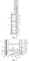
FIG. 2 is a schematic cross-sectional view of a display unit along A-A inFIG. 1 according to an embodiment of the present invention; -
FIG. 3 is a partially enlarged view of a part B inFIG. 2 ; -
FIG. 4 is a schematic exploded view of a display unit according to an embodiment of the present invention; -
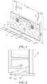
FIG. 5 is a schematic three-dimensional diagram when a bracket and a light guide member are separated according to an embodiment of the present invention; -
FIG. 6 is a schematic partial cross-sectional view of a bracket according to an embodiment of the present invention; -
FIG. 7 is a schematic three-dimensional diagram of a light guide member according to an embodiment of the present invention; -
FIG. 8 is a schematic cross-sectional view of a display unit according to another embodiment of the present invention; and -
FIG. 9 is a schematic three-dimensional diagram of a door of a refrigeration appliance having a display unit according to an embodiment of the present invention. - Referring to
FIG. 1 to FIG. 7 , adisplay unit 5 includes adisplay panel 54 and a printedcircuit board 53 located on a back side of thedisplay panel 54. In descriptions of this application, a side of thedisplay panel 54 facing away from the printedcircuit board 53 is a front side. Generally, after thedisplay panel 54 is mounted on a household appliance, the front side of thedisplay panel 54 can be touched and/or seen by a user. A side of thedisplay panel 54 facing the printedcircuit board 53 is a rear side or a back side. - In an embodiment, the
display panel 54 may include a transparent substrate and a lightproof layer attached to the transparent substrate. A light source of the printedcircuit board 53 illuminates a corresponding area of thedisplay panel 54 to display information to the user. - The printed
circuit board 53 has at least one first light-emitting element 531 configured to illuminate thedisplay panel 54 from the back side of thedisplay panel 54. - In an exemplary embodiment, the
printed circuit board 53 has a plurality of first light-emitting elements 531, and the plurality of first light-emitting elements 531 are spaced in a row. - The
display unit 5 may include atouch film 55 arranged along arear surface 548 of thedisplay panel 54. - The
touch film 55 may be sandwiched between thedisplay panel 54 and abracket 56. Thedisplay panel 54 may be fixed on a front side of thebracket 56 through a bonding apparatus. - When the user touches a corresponding area of the display panel 54 (for example, an
operation portion 512 schematically shown inFIG. 1 ), asensing portion 551 corresponding to thetouch film 55 may transmit a sensing signal to the printedcircuit board 53. - In an embodiment, the printed
circuit board 53 is located on a rear side of thebracket 56 facing away from thedisplay panel 54. Thetouch film 55 is connected to the printedcircuit board 53 through a connectingportion 552 spanning thebracket 56. - The printed
circuit board 53 includes a plurality of second light-emittingelements 532. The second light-emittingelement 532 is configured to illuminate adisplay portion 511 and theoperation portion 512 of thedisplay unit 5. Thebracket 56 has a plurality of spacedlight transmission slots 561, and light of the second light-emittingelement 532 may illuminate a corresponding area of thedisplay panel 54 through a correspondinglight transmission slot 561. The display portion and the operation portion may be arranged at different positions, or may be arranged at the same position. - The
display unit 5 may include arear cover 58, and the printedcircuit board 53 is located between thebracket 56 and therear cover 58. - The
display unit 5 includes alight guide member 57 configured to guide light of the first light-emittingelement 531 to a specific area of thedisplay panel 54. - In an exemplary embodiment, the
light guide member 57 is configured to guide the light emitted by the first light-emittingelement 531 to an edge area of thedisplay panel 54. In this way, a corresponding illuminated area of thedisplay panel 54 may be closer to anoutline 541 that can be seen by the user from the front side of thedisplay panel 54 than the first light-emittingelement 531, or even cover theoutline 541. - The
outline 541 may be formed by an intersection of afront surface 545 and anend surface 547 of thedisplay panel 54, where theend surface 547 connects thefront surface 545 and therear surface 548. In an exemplary embodiment, theoutline 541 may be an intersection edge between thefront surface 545 and theend surface 547. - Through illumination, the light illuminates an outermost edge area of the
display panel 54, so that the user can obtain, from the front side of thedisplay panel 54, an illuminatedarea 546 without a spacing from an outer contour of thedisplay panel 54. In this way, integration between thedisplay panel 54 and a periphery is enhanced. - In a variant embodiment, a slight spacing (for example, not greater than 1 millimeter) is maintained between the
illuminated area 546 and theoutline 541, and the spacing between theilluminated area 546 and theoutline 541 is not visible to naked eyes. The user sees that the illuminatedarea 546 extends inward by a predetermined distance from an outermost edge of thedisplay panel 54. - In an exemplary embodiment, the
light guide member 57 includes alight incident surface 571 facing the first light-emittingelement 531 and a lightoutgoing surface 572 facing therear surface 548 of thedisplay panel 54. In a direction parallel to thedisplay panel 54, the lightoutgoing surface 572 is closer to an edge of thedisplay panel 54 than thelight incident surface 571, and closer to theoutline 541 of thedisplay panel 54 in particular. - The
light guide member 57 may be arranged so that light entering from thelight incident surface 571 exits only from the lightoutgoing surface 572. - The light
outgoing surface 572 may be in a shape adapted to a shape of thedisplay panel 54. For example, the lightoutgoing surface 572 is a flat surface. - In an exemplary embodiment, the
outline 541 extends in a transverse direction X of thedisplay panel 54. Therefore, a spacing exists between the lightoutgoing surface 572 and the first light-emittingelement 531, and between thelight incident surface 571 and the first light-emittingelement 531 in a height direction Y of thedisplay panel 54. It should be understood that, if the outline extends in the height direction of the display panel, a spacing may exist between the lightoutgoing surface 572 and the first light-emittingelement 531, and between thelight incident surface 571 and the first light-emittingelement 531 in the transverse direction X of thedisplay panel 54. -
FIG. 1 schematically shows the illuminatedarea 546 of thedisplay panel 54 illuminated by the light transmitted from thelight guide member 57. In this embodiment, the illuminatedarea 546 covers theoutline 541 extending along a lower edge of thedisplay panel 54. - As shown in
FIG. 2 and FIG. 3 , thedisplay panel 54 includes theend surface 547 connected to thefront surface 545 and therear surface 548 of thedisplay panel 54. In a direction Z perpendicular to thedisplay panel 54, a projection of theend surface 547 is located within the lightoutgoing surface 572. - The
light guide member 57 includes aperipheral surface 573 connected to the lightoutgoing surface 572, and theperipheral surface 573 is flush with theend surface 547. Theperipheral surface 573 is close to the lightoutgoing surface 572 and may be perpendicularly connected to the lightoutgoing surface 572. - The
light guide member 57 may be exposed to an outer side of thedisplay unit 5. A part of thelight guide member 57 located outside thedisplay unit 5 may form a part of an outer surface of thedisplay unit 5. - The part of the
light guide member 57 exposed outside thedisplay unit 5 is located between the lightoutgoing surface 572 and thelight incident surface 571. Thelight guide member 57 may be arranged so that light is not transmitted out from the part exposed to the outer side of thedisplay unit 5. As shown inFIG. 2 and FIG. 3 , theperipheral surface 573 is exposed to the outer side of thedisplay unit 5, to be touchable from the outer side of thedisplay unit 5. On an outer peripheral surface of thedisplay unit 5, theend surface 547 and thelight guide member 57 may be flush. - The
light guide member 573 includes an inclinedlight guide portion 574 located between thelight incident surface 571 and the lightoutgoing surface 572, so that a transmission path of light in the light guide member has a distance in the direction parallel to thedisplay panel 54. In this way, the light emitted by the first light-emittingelement 531 can illuminate the edge area of thedisplay panel 54. - The
display unit 5 includes aperipheral wall 565 located between the printedcircuit board 53 and thedisplay panel 54 in the direction perpendicular to thedisplay panel 54. Theperipheral wall 565 has awindow 566, and thelight guide member 57 is located in thewindow 566. Therefore, thelight guide member 57 is exposed outside thedisplay unit 5. - The
window 566 may be closed by thelight guide member 57, as shown inFIG. 3 . In the direction perpendicular to thedisplay panel 54, the lightoutgoing surface 572 overlaps with thewindow 566. Therefore, the illuminatedarea 546 illuminated by the lightoutgoing surface 572 overlaps with thewindow 566. Theperipheral surface 573 located in thewindow 566 and exposed outside thedisplay unit 5 may be a flat surface. Therefore, after thewindow 566 is closed, it is possible that theperipheral surface 573 and theperipheral wall 565 may be substantially located in the same plane and be substantially flush. - The
display unit 5 may include achamber 59 located behind thedisplay panel 54 and configured to accommodate at least a part of the printedcircuit board 53. The first light-emittingelement 531 is located in thechamber 59. Thelight guide member 57 extends from inside thechamber 59 to outside thechamber 59. Theperipheral wall 565 defines a part of a boundary of thechamber 59. - In the direction perpendicular to the
display panel 54, the illuminatedarea 546 of thedisplay panel 54 illuminated by thelight guide member 57 and the lightoutgoing surface 572 overlap with theperipheral wall 565 defining thechamber 59. In this way, a technical problem in the related art that the illuminated area of thedisplay panel 54 cannot exceed an outer surface of theperipheral wall 565 can be resolved. - The printed
circuit board 53 may be supported on thebracket 56. Theperipheral wall 565 is located in thebracket 56, so that thebracket 56 forms a part of the outer peripheral surface of thedisplay unit 54. - The
bracket 56 includes a receivingslot 567 configured to receive thelight guide member 57. The receivingslot 567 communicates thechamber 59 with a front side and a peripheral side of thebracket 56. In this way, the receivingslot 567 is open on a front side facing thedisplay panel 54 and on a peripheral side. In an embodiment, the receivingslot 567 is open downward. - A front end of the
light guide member 57 extends out of the receivingslot 567, and is located in aspace 568 formed between thedisplay panel 54 and thebracket 56. The lightoutgoing surface 572 is located in thespace 568 and faces therear surface 548 of thedisplay panel 54. Theperipheral surface 573 is exposed outside of thedisplay unit 5 at thespace 568. - In an exemplary embodiment, the
light guide member 57 extends along an entire width of thedisplay unit 5, so that the receivingslot 567 also extends along the entire width of thedisplay unit 5. Two ends of thelight guide member 57 may be exposed on two sides of thedisplay unit 5 in a transverse direction. - The
light guide member 57 is adapted to be inserted into the receivingslot 567 from the front side of thebracket 56. As shown inFIG. 2, FIG. 3 , andFIG. 6 , thelight guide member 57 is clamped on thebracket 57. Thelight guide member 57 includes a plurality ofhook portions 575 protruding upward. After thelight guide member 57 is inserted into the receivingslot 567 from the front side of thebracket 56, thehook portions 575 are hooked with a free end of anelastic arm 569 of thebracket 57, thereby preventing thelight guide member 57 from exiting the receivingslot 567. - A rear end of the
elastic arm 569 is the free end. In a process in which thelight guide member 57 is inserted into the receivingslot 567, theelastic arm 569 deforms upward under an action of a top end of thehook portion 575, to allow thehook portion 575 to enter thelight guide member 57 to move to thelight incident surface 571, to become close to the first light-emittingelement 531. At a mounted position, due to matching between thehook portion 575 and theelastic arm 569, movement of thelight guide member 57 in a front-rear direction is limited. - A guide structure configured to locate the
light guide member 57 and guide insertion of thelight guide member 57 into the receivingslot 567 is arranged between thebracket 56 and thelight guide member 57. The guide structure may include a plurality of guide blocks 576 protruding upward from thelight guide member 57, and thelight guide member 57 has aguide groove 5691 adapted to receive theguide block 576. - The
bracket 56 includes aninclined wall 5692 defining a part of a boundary of the receivingslot 567. In an exemplary embodiment, theinclined wall 5692 defines at least a part of a lower groove surface of the receivingslot 567. Theinclined wall 5692 is inclined upward in a front-to-rear direction. Thelight guide member 57 has an inclined surface corresponding to theinclined wall 5692. - In a process of assembling the
light guide member 57 onto thebracket 56, theguide block 576 is aligned with acorresponding guide groove 5691 to be limited in a left-right direction, and through guidance of theinclined wall 5692, a rear end of thelight guide member 57 moves upward, and finally thelight incident surface 571 located at the rear end of thelight guide member 57 is aligned with a corresponding first light-emittingelement 531. - In an exemplary embodiment, the plurality of first light-emitting
elements 531 are arranged in a row on an edge of the printedcircuit board 53. Thelight guide member 57 has a plurality oflight incident portions 578 spaced apart at a rear portion. Eachlight incident portion 578 is aligned with one or a group of corresponding first light-emittingelements 531, so that light of the corresponding first light-emittingelements 531 enters thelight guide member 57 from alight incident surface 571 of the correspondinglight incident portion 578. - In an exemplary embodiment, the
light guide member 57 includes a lightoutgoing portion 579 connected to front sides of the plurality oflight incident portions 578, and the lightoutgoing surface 572 is located at front ends of the lightoutgoing portion 579. The lightoutgoing portion 579 is continuously arranged, so that the lightoutgoing surface 572 is continuous. - In this way, while a continuous
illuminated area 546 can be obtained on thedisplay panel 54, the first light-emittingelement 531 is independently controlled, so that the illuminatedarea 546 may be controlled partially. - In an exemplary embodiment, the illuminated
area 546 may be in a strip shape extending along the edge of thedisplay panel 54. The first light-emittingelement 531 may be used as ambient lighting and/or for an indication function. - In an exemplary embodiment, there is no gap between the
illuminated area 546 and theoutline 541. In other words, thedisplay panel 54 is illuminated from theoutline 541 visible at the front end, and the illuminatedarea 546 extends a preset distance to the other side of thedisplay unit 5. - It should be understood that, in an alternative embodiment, when the
light guide member 57 transmits the light of the first light-emittingelement 531 toward theoutline 541 by the preset distance to reduce a distance between the illuminated area and theoutline 541, a gap may exist between theilluminated area 546 and theoutline 541. In this way, a relationship between the illuminated area and theoutline 541 may be arranged according to design requirements. -
FIG. 8 is a schematic cross-sectional view of a display unit according to another embodiment of the present invention. As shown inFIG. 8 , a printedcircuit board 53a is located between adisplay panel 54a and abracket 56a. Alight guide member 57a guides light of a first light-emittingelement 531a located on the printedcircuit board 53a to an edge area of thedisplay panel 54a. Alight incident surface 571a and a lightoutgoing surface 572a of thelight guide member 57a are at a distance in a height direction of thedisplay unit 5a, so that an illuminatedarea 546a of thedisplay panel 5a illuminated by the first light-emittingelement 531a is closer to an edge of thedisplay panel 5a than the first light-emittingelement 531a. - In this embodiment, the illuminated
area 546a illuminated by the light guide member of thedisplay panel 5a and the lightoutgoing surface 572a extend outside the outer surface of theperipheral wall 565 defining thedisplay unit 5a in a direction parallel to thedisplay panel 5a. This is particularly conducive when an end surface of thedisplay panel 5a needs to exceed theperipheral wall 565. -
FIG. 9 shows adoor 2 of a refrigeration appliance having thedisplay unit 5 according to an embodiment of the present invention. Thedoor 2 is configured to close a storage compartment (not shown) of the refrigeration appliance (not shown). Thedoor 2 includes anallocation cavity 41 recessed backward from a front side of thedoor 2 and thedisplay unit 5 arranged along a side of theallocation cavity 41. An edge of thedisplay unit 5 close to theallocation cavity 41 may be illuminated, and anilluminated area 546 of thedisplay unit 5 covers anoutline 541 of thedisplay panel 54 close to theallocation cavity 41. - In this way, from a front side of the refrigeration appliance, the illuminated
area 546 and theallocation cavity 41 are seamlessly connected. This can significantly enhance integration between thedisplay unit 5 and theallocation cavity 41. The foregoing technical advantages of the display unit based on the embodiments of the present invention can be obtained without significantly complicating an overall layout of thedisplay unit 5. - A
peripheral surface 574 of thelight guide member 5 is exposed in theallocation cavity 41 due to being exposed on a lower side of thedisplay unit 5. - It may be understood that the
display units display units - Various embodiments of single components described with reference to
FIG. 1 to FIG. 9 may be combined with each other in any given manner, to achieve the advantages of the present invention. In addition, the present invention is not limited to the shown embodiments, and generally, other means than the shown means may also be used, provided that the means can also achieve the same effect.
Claims (14)
- A display unit configured for a household appliance, characterized by comprising:a display panel (54, 54a);a printed circuit board (53, 53a), comprising at least one first light-emitting element (531, 531a) configured to illuminate the display panel; anda light guide member (57, 57a), comprising a light incident surface (571, 571a) facing the first light-emitting element and a light outgoing surface (572, 572a) facing a rear side of the display panel, wherein the light outgoing surface is closer to an edge of the display panel than the light incident surface in a direction parallel to the printed circuit board.
- The display unit according to claim 1, characterized in that
the display panel comprises an illuminated area capable of being illuminated by the light outgoing surface, and the illuminated area comprises an outline of the display panel at the edge. - The display unit according to claim 1 or 2, characterized in that
the display panel comprises an end surface connecting a front surface and a rear surface of the display panel, and in a direction perpendicular to the display panel, a projection of the end surface is located on the light outgoing surface. - The display unit according to one or more of claims 1 to 3, characterized in that the light guide member comprises a peripheral surface connected to the light outgoing surface, and the peripheral surface is flush with the end surface.
- The display unit according to one or more of claims 1 to 4, characterized in that the display unit comprises a peripheral wall located between the printed circuit board and the display panel in a direction perpendicular to the display panel, the peripheral wall has a window, and the light guide member is located in the window.
- The display unit according to claim 5, characterized in thatin the direction perpendicular to the display panel, the light outgoing surface overlaps with the window; and/orin the direction perpendicular to the display panel, an illuminated area of the display panel illuminated by the light outgoing surface overlaps with the window; and/orthe window is closed by the light guide member; and/ora part of the light guide member exposed outside the display unit is flush with the peripheral wall.
- The display unit according to one or more of claims 1 to 6, characterized by comprising a chamber located behind the display panel and configured to accommodate at least a part of the printed circuit board, wherein the first light-emitting element is located in the chamber, and the light guide member extends from inside the chamber to outside the chamber, to illuminate the rear side of the display panel.
- The display unit according to one or more of claims 1 to 7, characterized by comprising a bracket located behind the display panel, whereinthe bracket comprises at least a part of a peripheral wall defining the display unit, and the peripheral wall has a window configured to accommodate the light guide member; and/orthe bracket comprises a receiving slot configured to receive the light guide member, and the receiving slot is open on a front side facing the display panel and on a peripheral side; and/orthe light guide member is clamped in the bracket; and/orthe bracket has an elastic arm, and the light guide member has a hook portion matching the elastic arm.
- The display unit according to claim 8, characterized in thatthe printed circuit board comprises at least one second light-emitting element, the bracket has a light transmission slot running through the bracket, and light of the at least one second light-emitting element is configured to emit to the display panel through the light transmission slot; and/orthe printed circuit board is supported on a back side of the bracket, the display panel is located on a front side of the bracket, and the first light-emitting element emits light suitable to pass through the bracket to illuminate the display panel; and/orthe receiving slot extends obliquely; and/orthe receiving slot extends over an entire width of the bracket; and/orthe light guide member extends over the entire width of the bracket.
- The display unit according to one or more of claims 1 to 9, characterized in thatthe light guide member is exposed outside the display unit; and/orat least a part of a section of the light guide member between the light incident surface and the light outgoing surface extends obliquely, enabling a transmission path of light in the light guide member has a distance in a direction parallel to the display panel.
- The display unit according to claim 10, characterized in that the light guide member comprises a part exposed outside the display unit and located between the light outgoing surface and the light incident surface; and/or two ends of the light guide member are exposed on two sides of the display unit.
- The display unit according to one or more of claims 1 to 11, characterized in thatthe light guide member comprises a plurality of light incident portions spaced apart, and each light incident portion has a light incident surface corresponding to one or a group of first light-emitting elements; and/orthe light guide member comprises a light outgoing portion, and the light outgoing surface continuously extends at a front end of the light outgoing portion.
- A household appliance, comprising the display unit according to any one of the foregoing claims.
- The household appliance according to claim 13, characterized by comprising an allocation cavity, wherein the display unit is distributed along a side of the allocation cavity, and the light guide member is exposed to the allocation cavity.
Applications Claiming Priority (1)
| Application Number | Priority Date | Filing Date | Title |
|---|---|---|---|
| CN202311863066.9A CN120236470A (en) | 2023-12-29 | 2023-12-29 | Display unit and household appliance having the same |
Publications (1)
| Publication Number | Publication Date |
|---|---|
| EP4579126A1 true EP4579126A1 (en) | 2025-07-02 |
Family
ID=93799518
Family Applications (1)
| Application Number | Title | Priority Date | Filing Date |
|---|---|---|---|
| EP24217418.3A Pending EP4579126A1 (en) | 2023-12-29 | 2024-12-04 | Display unit and household appliance having display unit |
Country Status (3)
| Country | Link |
|---|---|
| US (1) | US12468085B2 (en) |
| EP (1) | EP4579126A1 (en) |
| CN (1) | CN120236470A (en) |
Citations (6)
| Publication number | Priority date | Publication date | Assignee | Title |
|---|---|---|---|---|
| EP2455930A1 (en) * | 2010-11-19 | 2012-05-23 | Electrolux Home Products Corporation N.V. | A display for indicating an operational progress of an apparatus, in particular a household appliance |
| US20170350603A1 (en) * | 2016-06-03 | 2017-12-07 | Samsung Electronics Co., Ltd. | Oven |
| CN105698481B (en) * | 2016-03-09 | 2018-10-12 | 青岛海尔股份有限公司 | Display device and refrigerator drawer |
| EP3170044B1 (en) * | 2014-07-16 | 2019-11-20 | BSH Hausgeräte GmbH | Display device and domestic appliance having such a display device |
| US11266291B1 (en) * | 2020-12-08 | 2022-03-08 | Haier Us Appliance Solutions, Inc. | Dishwasher appliance with a sidefire LED lightguide |
| CN115407902A (en) * | 2021-05-26 | 2022-11-29 | Bsh家用电器有限公司 | Display and operating device |
Family Cites Families (1)
| Publication number | Priority date | Publication date | Assignee | Title |
|---|---|---|---|---|
| US10416372B2 (en) * | 2017-05-25 | 2019-09-17 | Haier Us Appliance Solutions, Inc. | Appliance with a control panel |
-
2023
- 2023-12-29 CN CN202311863066.9A patent/CN120236470A/en active Pending
-
2024
- 2024-11-13 US US18/946,068 patent/US12468085B2/en active Active
- 2024-12-04 EP EP24217418.3A patent/EP4579126A1/en active Pending
Patent Citations (6)
| Publication number | Priority date | Publication date | Assignee | Title |
|---|---|---|---|---|
| EP2455930A1 (en) * | 2010-11-19 | 2012-05-23 | Electrolux Home Products Corporation N.V. | A display for indicating an operational progress of an apparatus, in particular a household appliance |
| EP3170044B1 (en) * | 2014-07-16 | 2019-11-20 | BSH Hausgeräte GmbH | Display device and domestic appliance having such a display device |
| CN105698481B (en) * | 2016-03-09 | 2018-10-12 | 青岛海尔股份有限公司 | Display device and refrigerator drawer |
| US20170350603A1 (en) * | 2016-06-03 | 2017-12-07 | Samsung Electronics Co., Ltd. | Oven |
| US11266291B1 (en) * | 2020-12-08 | 2022-03-08 | Haier Us Appliance Solutions, Inc. | Dishwasher appliance with a sidefire LED lightguide |
| CN115407902A (en) * | 2021-05-26 | 2022-11-29 | Bsh家用电器有限公司 | Display and operating device |
Also Published As
| Publication number | Publication date |
|---|---|
| US12468085B2 (en) | 2025-11-11 |
| US20250216594A1 (en) | 2025-07-03 |
| CN120236470A (en) | 2025-07-01 |
Similar Documents
| Publication | Publication Date | Title |
|---|---|---|
| CN107560276B (en) | refrigerator | |
| JP5988880B2 (en) | refrigerator | |
| CN101325902B (en) | Domestic appliance, in particular fitted domestic appliance with a controllable operating display | |
| US20080225016A1 (en) | Control panel and washing machine having the same | |
| EP2031112B1 (en) | Clothes handling apparatus having button for control panel assembly | |
| JP2012533198A (en) | Operation unit for electrical equipment | |
| JP5932630B2 (en) | refrigerator | |
| US12405049B2 (en) | Refrigerator | |
| CN100473321C (en) | Domestic appliance | |
| US12468085B2 (en) | Display unit and household appliance having a display unit | |
| CN115407902B (en) | Display and operation device | |
| JP6628337B2 (en) | Gaming machine | |
| JP2018013305A (en) | refrigerator | |
| US20180340728A1 (en) | Appliance with a control panel | |
| JP7178771B2 (en) | refrigerator | |
| KR200443891Y1 (en) | Volume knob lighting structure of AV device | |
| CN116576620A (en) | Refrigerating appliance and manufacturing method thereof | |
| US12352997B2 (en) | Light guide plate unit and gaming machine | |
| KR20060071660A (en) | Refrigerator | |
| CN218153791U (en) | Household electrical appliance | |
| JP6633987B2 (en) | refrigerator | |
| CN111189291B (en) | Refrigerator drawers and refrigerators | |
| CN111189289A (en) | Upper cover assembly of drawer, drawer and refrigerator | |
| JP3794337B2 (en) | Operation panel unit | |
| CN108397968A (en) | Refrigerator |
Legal Events
| Date | Code | Title | Description |
|---|---|---|---|
| PUAI | Public reference made under article 153(3) epc to a published international application that has entered the european phase |
Free format text: ORIGINAL CODE: 0009012 |
|
| STAA | Information on the status of an ep patent application or granted ep patent |
Free format text: STATUS: THE APPLICATION HAS BEEN PUBLISHED |
|
| AK | Designated contracting states |
Kind code of ref document: A1 Designated state(s): AL AT BE BG CH CY CZ DE DK EE ES FI FR GB GR HR HU IE IS IT LI LT LU LV MC ME MK MT NL NO PL PT RO RS SE SI SK SM TR |
|
| STAA | Information on the status of an ep patent application or granted ep patent |
Free format text: STATUS: REQUEST FOR EXAMINATION WAS MADE |
|
| 17P | Request for examination filed |
Effective date: 20260102 |