EP4579113A1 - Heat insulating wall and heat insulating container - Google Patents
Heat insulating wall and heat insulating container Download PDFInfo
- Publication number
- EP4579113A1 EP4579113A1 EP23856928.9A EP23856928A EP4579113A1 EP 4579113 A1 EP4579113 A1 EP 4579113A1 EP 23856928 A EP23856928 A EP 23856928A EP 4579113 A1 EP4579113 A1 EP 4579113A1
- Authority
- EP
- European Patent Office
- Prior art keywords
- cells
- heat
- layer
- cell
- core
- Prior art date
- Legal status (The legal status is an assumption and is not a legal conclusion. Google has not performed a legal analysis and makes no representation as to the accuracy of the status listed.)
- Withdrawn
Links
Images




Classifications
-
- F—MECHANICAL ENGINEERING; LIGHTING; HEATING; WEAPONS; BLASTING
- F16—ENGINEERING ELEMENTS AND UNITS; GENERAL MEASURES FOR PRODUCING AND MAINTAINING EFFECTIVE FUNCTIONING OF MACHINES OR INSTALLATIONS; THERMAL INSULATION IN GENERAL
- F16L—PIPES; JOINTS OR FITTINGS FOR PIPES; SUPPORTS FOR PIPES, CABLES OR PROTECTIVE TUBING; MEANS FOR THERMAL INSULATION IN GENERAL
- F16L59/00—Thermal insulation in general
- F16L59/06—Arrangements using an air layer or vacuum
-
- B—PERFORMING OPERATIONS; TRANSPORTING
- B32—LAYERED PRODUCTS
- B32B—LAYERED PRODUCTS, i.e. PRODUCTS BUILT-UP OF STRATA OF FLAT OR NON-FLAT, e.g. CELLULAR OR HONEYCOMB, FORM
- B32B27/00—Layered products comprising a layer of synthetic resin
- B32B27/06—Layered products comprising a layer of synthetic resin as the main or only constituent of a layer, which is next to another layer of the same or of a different material
- B32B27/065—Layered products comprising a layer of synthetic resin as the main or only constituent of a layer, which is next to another layer of the same or of a different material of foam
-
- B—PERFORMING OPERATIONS; TRANSPORTING
- B32—LAYERED PRODUCTS
- B32B—LAYERED PRODUCTS, i.e. PRODUCTS BUILT-UP OF STRATA OF FLAT OR NON-FLAT, e.g. CELLULAR OR HONEYCOMB, FORM
- B32B5/00—Layered products characterised by the non- homogeneity or physical structure, i.e. comprising a fibrous, filamentary, particulate or foam layer; Layered products characterised by having a layer differing constitutionally or physically in different parts
- B32B5/18—Layered products characterised by the non- homogeneity or physical structure, i.e. comprising a fibrous, filamentary, particulate or foam layer; Layered products characterised by having a layer differing constitutionally or physically in different parts characterised by features of a layer of foamed material
-
- B—PERFORMING OPERATIONS; TRANSPORTING
- B32—LAYERED PRODUCTS
- B32B—LAYERED PRODUCTS, i.e. PRODUCTS BUILT-UP OF STRATA OF FLAT OR NON-FLAT, e.g. CELLULAR OR HONEYCOMB, FORM
- B32B2266/00—Composition of foam
- B32B2266/02—Organic
- B32B2266/0214—Materials belonging to B32B27/00
- B32B2266/0278—Polyurethane
-
- B—PERFORMING OPERATIONS; TRANSPORTING
- B32—LAYERED PRODUCTS
- B32B—LAYERED PRODUCTS, i.e. PRODUCTS BUILT-UP OF STRATA OF FLAT OR NON-FLAT, e.g. CELLULAR OR HONEYCOMB, FORM
- B32B2266/00—Composition of foam
- B32B2266/06—Open cell foam
-
- B—PERFORMING OPERATIONS; TRANSPORTING
- B32—LAYERED PRODUCTS
- B32B—LAYERED PRODUCTS, i.e. PRODUCTS BUILT-UP OF STRATA OF FLAT OR NON-FLAT, e.g. CELLULAR OR HONEYCOMB, FORM
- B32B2266/00—Composition of foam
- B32B2266/10—Composition of foam characterised by the foam pores
-
- B—PERFORMING OPERATIONS; TRANSPORTING
- B32—LAYERED PRODUCTS
- B32B—LAYERED PRODUCTS, i.e. PRODUCTS BUILT-UP OF STRATA OF FLAT OR NON-FLAT, e.g. CELLULAR OR HONEYCOMB, FORM
- B32B2307/00—Properties of the layers or laminate
- B32B2307/30—Properties of the layers or laminate having particular thermal properties
- B32B2307/304—Insulating
-
- B—PERFORMING OPERATIONS; TRANSPORTING
- B32—LAYERED PRODUCTS
- B32B—LAYERED PRODUCTS, i.e. PRODUCTS BUILT-UP OF STRATA OF FLAT OR NON-FLAT, e.g. CELLULAR OR HONEYCOMB, FORM
- B32B2439/00—Containers; Receptacles
- B32B2439/02—Open containers
-
- B—PERFORMING OPERATIONS; TRANSPORTING
- B32—LAYERED PRODUCTS
- B32B—LAYERED PRODUCTS, i.e. PRODUCTS BUILT-UP OF STRATA OF FLAT OR NON-FLAT, e.g. CELLULAR OR HONEYCOMB, FORM
- B32B2439/00—Containers; Receptacles
- B32B2439/40—Closed containers
- B32B2439/62—Boxes, cartons, cases
Definitions
- the present disclosure relates to a heat-insulating wall and a heat-insulating container.
- a heat-insulating box body of PTL 1 has been known as a heat-insulating wall.
- PTL 1 describes that this heat-insulating box body is formed such that: a hollow portion of a casing thereof is filled with urethane foam; and an inside of the hollow portion is made vacuum by discharging air.
- the skin layer 36 spreads in the orthogonal direction to cover the plurality of cells 40 that are dispersed in the orthogonal direction. Moreover, as shown in the example of FIGS. 4 and 5B , the skin layer 36 covers the cells 40 which are located closest to the surface 31 among the plurality of cells 40 dispersed in the thickness direction.
- a thickness L1 of the skin layer 36 is 20 ⁇ m or less, and is, for example, 2 ⁇ m or more and 20 ⁇ m or less.
- a plurality of polyol mixtures that are different in composition from each other are used as the compound including the hydroxyl group.
- distortions are generated at the molecular level due to the differences among the compositions of the plurality of polyols.
- the planar dividing wall 34 breaks by the distortions, and the communication hole 43 penetrating the planar dividing wall 34 is formed.
- the skin layer 36 breaks due to the distortions at the molecular level, and the through hole 46 penetrating the skin layer 36 is formed.
- the through hole 46 is formed at the corner portion 33 of the core 30.
- a parting line along which the mold is divided is located at the corner portion 33 of the core 30 made of the urethane foam released from the mold, and burrs 37 may be formed on the surface 31 of the core 30 along this parting line.
- the skin layer 36 forming the surface 31 of the core 30 breaks, and the through hole 46 penetrating the skin layer 36 is formed.
- the through holes 46 and the communication holes 43 are formed at the core 30 by one or a plurality of methods.
- the cells 40 in the core 30 communicate with the outside of the core 30 through the through holes 46 and the communication holes 43. Therefore, air in the cells 40 is discharged to the outside of the core 30 through the through holes 46 and the communication holes 43.
- the inside of the core 30 is reduced in pressure, and heat conduction by the air is reduced.
- the heat insulating property of the heat-insulating wall 20 can be improved.
- the thickness of the planar dividing wall 34 of the skin layer 36 is reduced. Therefore, the through holes 46 are easily formed on the skin layer 36 by the stress of the cell 40, the distortions at the molecular level, and the removal of the burrs 37. Thus, particles for the formation of the through holes 46 do not have to be added to the urethane liquid. Therefore, a step of adding the particles and a facility that is highly durable against the particles are not required, and an increase in viscosity due to the particles does not occur. Thus, the heat insulating property of the heat-insulating wall 20 can be improved while suppressing a cost increase by the addition of the particles.
- the inner layer 38 includes a first layer 38a.
- the first layer 38a is located farther from the outer cover 21 in the thickness direction than the skin layer 36.
- the first layer 38a is laminated on the skin layer 36.
- a thickness L2 of the first layer 38a in the thickness direction is 5 mm or less.
- the cells 40 included in the first layer 38a includes flat cells 44 each having a flat ellipsoidal shape.
- Each flat cell 44 has such a flat ellipsoidal shape that a dimension in the thickness direction is smaller than a dimension in the orthogonal direction.
- the flat cell 44 includes three axes that are a minor axis, a first major axis, and a second major axis.
- the minor axis, the first major axis, and the second major axis are orthogonal to each other.
- the flat cell 44 has a rotating body shape formed such that the minor axis is regarded as a rotation axis.
- a dimension M0 along the minor axis is shorter than each of a dimension M1 along the first major axis and a dimension M2 along the second major axis.
- the dimension M1 along the first major axis and the dimension M2 along the second major axis are equal to each other or substantially equal to each other. Therefore, a section of the flat cell 44 which is orthogonal to the minor axis has a circular shape or a substantially circular shape.
- a section of the flat cell 44 which is orthogonal to the first major axis has an oval shape or a substantially oval shape.
- a section of the flat cell 44 which is orthogonal to the second major axis has an oval shape or a substantially oval shape.
- an angle ⁇ 1 between the thickness direction of the core 30 and the minor axis of the flat cell 44 is smaller than an angle ⁇ 2 between the orthogonal direction of the core 30 and the minor axis of the flat cell 44. Therefore, the flat cell 44 is located in the first layer 38a of the core 30 such that a dimension N0 of the flat cell 44 in the thickness direction of the core 30 is smaller than a dimension N1 of the flat cell 44 in the orthogonal direction. Therefore, the number of flat cells 44 in the thickness direction increases. Thus, a heat transfer route of the heat-insulating wall 20 in the thickness direction increases, and the heat insulating property of the heat-insulating wall 20 can be improved.
- the dimension of the flat cell 44 in the orthogonal direction becomes larger than the dimension of the flat cell 44 in the thickness direction.
- the planar dividing wall 34 between the flat cells 44 adjacent to each other in the orthogonal direction breaks, and the communication hole 43 through which the flat cells 44 communicate with each other is easily formed. Therefore, at least one of the number of communication holes 43 or the areas of the communication holes 43 increases by the flat cells 44.
- some or all of the flat cells 44 in the core 30 communicate with the outside of the core 30 through the other cells 40, the through holes 46, the communication holes 43, and the like. Therefore, the air discharging efficiency from the cells 40 of the core 30 to the outside of the core 30 is improved, and the heat insulating property of the heat-insulating wall 20 can be improved.
- heat conductivity of the heat-insulating wall 20 in the thickness direction is smaller than heat conductivity of the heat-insulating wall 20 in the orthogonal direction. Therefore, in the heat-insulating wall 20, the amount of heat transferred in the thickness direction per unit time and per unit area is smaller than the amount of heat transferred in the orthogonal direction per unit time and per unit area. Thus, the amount of heat transferred from the outside of the heat-insulating container 10 through the heat-insulating wall 20 to the container space 14 can be reduced, and a heat retaining time of the container space 14 can be lengthened.
- the heat conductivity of the heat-insulating wall 20 in the orthogonal direction is larger than the heat conductivity of the heat-insulating wall 20 in the thickness direction. Therefore, for example, when the container space 14 of the heat-insulating container 10 is cooled by a cooling agent, the temperature of the cooling agent and the temperature of the heat-insulating wall 20 are uniformized in the orthogonal direction. Thus, a uniform cold reserving effect of a cold reserving material can be lengthened, and the temperature of the container space 14 of the heat-insulating container 10 can be uniformized.
- the cells 40 included in the first layer 38a may include spherical cells 45 each having a spherical shape in addition to the flat cells 44 each having the flat ellipsoidal shape. Some or all of the spherical cells 45 in the core 30 communicate with the outside of the core 30 through the other cells 40, the through holes 46, the communication holes 43, and the like.
- the flat cell 44 tends to be deformed more than the spherical cell 45 and tends to more largely break than the spherical cell 45. Therefore, an average number of communication holes 43 through which the flat cell 44 communicates with the other cells 40 is larger than an average number of communication holes 43 through which the spherical cell 45 communicates with the other cells 40.
- the average number of communication holes 43 of the flat cell 44 is a quotient obtained in such a manner that a total number of communication holes 43 through which a predetermined number of flat cells 44, i.e., two or more flat cells 44 communicate with the other cells 40 is divided by the predetermined number of flat cells 44.
- the average number of communication holes 43 through which the spherical cell 45 communicates with the other cells is a quotient obtained in such a manner that a total number of communication holes 43 through which a predetermined number of spherical cells 45, i.e., two or more spherical cells 45 communicate with the other cells 40 is divided by the predetermined number of spherical cells 45.
- the communication holes 43 in the core 30 increase by the flat cells 44. Therefore, the air discharging efficiency from the cells 40 of the core 30 to the outside of the core 30 is improved, and the heat insulating property of the heat-insulating wall 20 can be improved.
- the flat cell 44 tends to be deformed more than the spherical cell 45 and tends to more largely break than the spherical cell 45. Therefore, an average area of the communication hole 43 through which the flat cell 44 communicates with another cell 40 is larger than an average area of the communication hole 43 through which the spherical cell 45 communicates with another cell 40.
- the average area of the communication hole 43 through which the flat cell 44 communicates with another cell 40 is a quotient obtained in such a manner that a total area of the communication holes 43 through which a predetermined number of flat cells 44, i.e., two or more flat cells 44 communicate with the other cells 40 is divided by the predetermined number of flat cells 44.
- the average area of the communication hole 43 through which the spherical cell 45 communicates with another cell 40 is a quotient obtained in such a manner that a total area of the communication holes 43 through which a predetermined number of spherical cells 45, i.e., two or more spherical cells 45 communicate with the other cells 40 is divided by the predetermined number of spherical cells 45.
- the areas of the communication holes 43 in the core 30 increase by the flat cells 44. Therefore, the air discharging efficiency from the cells 40 of the core 30 to the outside of the core 30 is improved, and the heat insulating property of the heat-insulating wall 20 can be improved.
- the inner layer 38 includes a second layer 38b.
- the second layer 38b is located farther from the skin layer 36 in the thickness direction than the first layer 38a.
- the second layer 38b is laminated on the first layer 38a.
- the skin layer 36, the first layer 38a, and the second layer 38b are laminated on each other in this order in the thickness direction in the core 30.
- the cells 40 included in the second layer 38b include the spherical cells 45.
- the volume of each cell 40 in the second layer 38b is larger than the volume of each cell 40 in the first layer 38a.
- the cells 40 included in the first layer 38a may include the spherical cells 45 in addition to the flat cells 44
- the cells 40 included in the second layer 38b may include the flat cells 44 in addition to the spherical cells 45.
- the first layer 38a may be a region of the inner layer 38 where the number of flat cells 44 per unit volume is not less than the number of spherical cells 45 per unit volume
- the second layer 38b may be a region of the inner layer 38 where the number of spherical cells 45 per unit volume is not less than the number of flat cells 44 per unit volume.
- a boundary between the first layer 38a and the second layer 38b in the inner layer 38 does not have to be clear.
- a fifth technology is the heat-insulating wall according to the third or fourth technology, wherein: the cells included in the first layer include a spherical cell having a spherical shape in addition to the flat cell; and an average area of a communication hole through which the flat cell communicates with another cell is larger than an average area of a communication hole through which the spherical cell communicates with another cell.
- the core includes such flat cell that the average area of the communication hole is large. Therefore, the air discharging efficiency from the cells of the core is improved, and the heat insulating property of the heat-insulating wall can be improved. Moreover, the core includes such spherical cell that the average area of the communication hole is small. Therefore, the strength that suppresses the deformation of the heat-insulating wall can be secured.
- a seventh technology is the heat-insulating wall according to any one of the third to sixth technologies, wherein: the inner layer included in the core includes a second layer located farther from the skin layer in the thickness direction than the first layer and laminated on the first layer; and the cells included in the second layer include a spherical cell having a spherical shape. According to this configuration, the strength that suppresses the deformation of the heat-insulating wall can be secured by the spherical cell.
- An eighth technology is a heat-insulating container including the heat-insulating wall according to any one of the first to seventh technologies. According to this configuration, both of the heat insulating property and strength of the heat-insulating container can be obtained by the heat-insulating wall which has been improved in the heat insulating property and the strength.
- a ninth technology is the heat-insulating container according to the eighth technology, wherein: the core includes a plurality of flat surface portions and a corner portion to which the plurality of flat surface portions are connected; and a ratio of the number of second cells to a sum of the number of first cells and the number of second cells in the flat surface portion per unit volume is larger than a ratio of the number of second cells to a sum of the number of first cells and the number of second cells in the corner portion per unit volume.
- the strength that suppresses the deformation of the heat-insulating container is secured at the corner portion by the structure in which the plurality of flat surface portions are connected to each other at the corner portion.
- the air discharging efficiency can be improved by a large number of first cells, and the heat insulating property can be improved.
- the strength that suppresses the deformation of the heat-insulating container can be secured at the flat surface portion by the skin layer for a large number of second cells.
- the heat-insulating wall and the heat-insulating container according to the present disclosure are applicable to a heat-insulating wall and a heat-insulating container which can obtain both of the strength and the heat insulating property.
Landscapes
- Engineering & Computer Science (AREA)
- General Engineering & Computer Science (AREA)
- Mechanical Engineering (AREA)
- Thermal Insulation (AREA)
- Packages (AREA)
Abstract
Description
- The present disclosure relates to a heat-insulating wall and a heat-insulating container.
- A heat-insulating box body of PTL 1 has been known as a heat-insulating wall. PTL 1 describes that this heat-insulating box body is formed such that: a hollow portion of a casing thereof is filled with urethane foam; and an inside of the hollow portion is made vacuum by discharging air.
- PTL 1:
Japanese Laid-Open Patent Application Publication No. 9-119771 - As with the heat-insulating box body of PTL 1, when the hollow portion of the casing is filled with the urethane foam, an airtight skin layer is formed on a surface of the urethane foam which is in contact an inner surface of the casing. The urethane foam is covered with this skin layer. Therefore, even when air is discharged from the inside of the hollow portion, the inside of the urethane foam cannot be made vacuum. Thus, a heat insulating property of the heat-insulating box body cannot be improved. Moreover, since a lot of air bubbles are contained in the urethane foam of the heat-insulating box body, the heat-insulating box body is easily deformed due to the air bubbles.
- The present disclosure was made to solve the above problems, and an object of the present disclosure is to provide a heat-insulating wall and a heat-insulating container each of which can obtain both of a heat insulating property and strength.
- A heat-insulating wall according to one aspect of the present disclosure includes: a core made of urethane foam including a plurality of cells; and an outer cover including an internal space accommodating the core, the internal space being reduced in pressure, wherein: the core includes a skin layer including a surface that is in contact with the outer cover and an inner layer including the plurality of cells and located farther from the outer cover than the skin layer; and the plurality of cells included in the inner layer includes a first cell that is open on the surface of the skin layer through the skin layer and a second cell that is not open on the surface of the skin layer.
- According to this configuration, the cells of the core communicate with the outside of the core through the first cell that is open on the surface. Since air is discharged from the cells of the core through the first cell to the outside, the heat insulating property of the heat-insulating wall can be improved. Moreover, since the skin layer covering the second cell is stretched tight, the strength that suppresses the deformation of the heat-insulating wall can be secured.
- The present disclosure can provide the heat-insulating wall and the heat-insulating container each of which can obtain both of the strength and the heat insulating property.
-
-
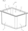
FIG. 1 is a perspective view showing one example of a heat-insulating container including a heat-insulating wall according to an embodiment of the present disclosure. -
FIG. 2 is a diagram showing a core and outer cover of the heat-insulating wall ofFIG. 1 . -
FIG. 3 is a perspective view showing the core ofFIG. 2 . -
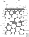
FIG. 4 is a sectional view showing the heat-insulating wall ofFIG. 1 . -
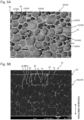
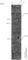
FIG. 5A is a SEM image of the core which is obtained by taking an image of a skin layer with a scanning electron microscope (SEM) after a first layer is cut along a section orthogonal to a thickness direction.FIG. 5B is a SEM image of the core which is obtained by taking an image of the skin layer and the first layer with the scanning electron microscope after the skin layer and the first layer are cut along a section parallel to the thickness direction. -
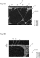
FIG. 6A is an enlarged image of a portion shown by a dotted line in the SEM image ofFIG. 5B .FIG. 6B is an enlarged image of a portion shown by a dotted line in the SEM image ofFIG. 6A . -
FIGS. 7A and 7B are the SEM images of the core each of which is obtained by taking an image of a planar dividing wall including communication holes with the scanning electron microscope. -
FIG. 8 is a SEM image of the core which is obtained by taking an image of the skin layer, the first layer, and a second layer with the scanning electron microscope after the skin layer, the first layer, and the second layer are cut along a section parallel to the thickness direction. -
FIG. 9A is a perspective view schematically showing a flat cell having a flat ellipsoidal shape.FIG. 9B shows sectional views obtained by cutting a third cell ofFIG. 9A along a minor axis, a first major axis, and a second major axis. -
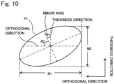
FIG. 10 is a diagram schematically showing a relation between the minor axis of the third cell ofFIG. 9A and the thickness direction of the core. - Hereinafter, an embodiment of the present disclosure will be specifically described with reference to the drawings. In the following description and the drawings, the same reference signs are used for the same or corresponding components.
- For example, a heat-insulating
container 10 according to the present disclosure has a box shape including anupper surface 11 that is open, and includes aninner surface 15, anouter surface 16, and acontainer space 14 that is an internal space. Theinner surface 15 surrounds thecontainer space 14, and theouter surface 16 surrounds theinner surface 15. Theupper surface 11 is connected to an outer peripheral edge of theinner surface 15 and an outer peripheral edge of theouter surface 16. - The heat-insulating
container 10 includes a heat-insulatingwall 20. In the example ofFIG. 1 , the heat-insulatingwall 20 is the same in shape and size as the heat-insulatingcontainer 10, and the heat-insulatingcontainer 10 is formed by one heat-insulatingwall 20. In this case, the heat-insulatingwall 20 is the same in meaning as the heat-insulatingcontainer 10. The shape of the heat-insulatingwall 20 and the number of heat-insulatingwalls 20 forming the heat-insulatingcontainer 10 are not limited to these. For example, the heat-insulatingwall 20 may have a flat plate shape. In this case, the heat-insulatingcontainer 10 may be formed by a plurality of (for example, five) heat-insulatingwalls 20. - As shown in the example of
FIG. 2 , the heat-insulatingwall 20 includes acore 30 and anouter cover 21. Thecore 30 is made of urethane foam including cells 40 (FIG. 4 ). Theouter cover 21 includes a heat-insulatingspace 22 that is an internal space accommodating thecore 30. The heat-insulatingspace 22 is reduced in pressure. Thecore 30 is a porous body including a large number of cells 40 (FIG. 4 ) and serves as a framework of the heat-insulatingwall 20. Thecells 40 are air bubbles (small spaces) generated by foaming in urethane. For example, thecore 30 is made of urethane resin and is rigid urethane foam. Details of the core 30 will be described later. - The
outer cover 21 has a gas barrier property, and the pressure of the heat-insulatingspace 22 is maintained lower than atmospheric pressure. For example, theouter cover 21 may be a laminated film including: a thermoplastic resin layer that can be subjected to thermal welding; an air barrier layer of an ethylene-vinyl alcohol copolymer, a polyvinyl alcohol polymer, or the like; and a steam barrier layer of polypropylene or the like. Moreover, theouter cover 21 may be a laminated film including, as a gas barrier layer, metal foil or a resin film on which metal is deposited. - The
outer cover 21 accommodates the core 30 in the heat-insulatingspace 22, covers asurface 31 of the core 30, and is sealed. The heat-insulatingspace 22 of theouter cover 21 may accommodate a gas adsorber in addition to thecore 30. The gas adsorber adsorbs gas, such as steam and air, remaining in or having entered the heat-insulatingspace 22 of theouter cover 21. Therefore, the pressure of the heat-insulatingspace 22 of theouter cover 21 can be maintained low. - As shown in the example of
FIG. 2 , the heat-insulatingwall 20 includes thecore 30 and theouter cover 21, and theouter cover 21 includes aninside member 23 and an outside member 24. Theinside member 23 has a box shape including an upper surface that is open, and aflange portion 23a is located so as to surround this opening portion. The outside member 24 has a box shape including an upper surface that is open, and aflange portion 24a is located so as to surround this opening portion. Each of theinside member 23 and the outside member 24 is formed to have a predetermined shape by vacuum forming, pressure forming, blow molding, or the like. - Moreover, a mold for the
core 30 is heated to a predetermined temperature, such as 50°C or higher, which is higher than a normal temperature (for example, 20°C±15°C), and a urethane liquid is poured into the heated mold. The urethane liquid includes: a compound including a hydroxyl group, such as polyol; polyisocyanate; and a chemical foaming agent, such as water. When a filling property and control of a reaction temperature are required, the urethane liquid may further include a physical foaming agent, such as hydrofluoroolefin. - In the mold, a polymerization reaction occurs between polyol and polyisocyanate in the urethane liquid. The foaming agent foams by being heated by heat generated by this polymerization reaction. Thus, a plurality of
cells 40 are formed in the urethane. Then, the urethane foam formed as above is released from the mold. Thus, the core 30 having a box shape including an upper end that is open is molded. Thesurface 31 of thecore 30 is a surface which has been in contact with the mold. - Then, the
core 30 is accommodated in the outside member 24, and theinside member 23 is accommodated in thecore 30. Thus, thecore 30 is accommodated in the heat-insulatingspace 22 between the outside member 24 and theinside member 23, and theflange portion 23a of theinside member 23 overlaps theflange portion 24a of the outside member 24 from above. Theflange portion 24a and theflange portion 23a are welded to each other, and the heat-insulatingspace 22 is subjected to vacuum drawing through an opening portion located at theinside member 23 or the outside member 24. Thus, the heat-insulatingspace 22 is reduced in pressure, and theinside member 23 and the outside member 24 are brought into tight contact with thesurface 31 of thecore 30. Then, by sealing the opening portion with a sealant, theouter cover 21 is sealed. Thus, the heat-insulatingwall 20 including the heat-insulatingspace 22 whose pressure is lower than the atmospheric pressure is produced. In this case, theinside member 23 constitutes the inner surface 15 (FIG. 1 ) of the heat-insulatingwall 20, and the outside member 24 constitutes the outer surface 16 (FIG. 1 ) of the heat-insulatingwall 20. - As shown in the example of
FIG. 3 , thecore 30 of the heat-insulatingwall 20 has a box shape including an upper surface that is open, and includes fiveflat surface portions 32 and acorner portion 33. Four of the fiveflat surface portions 32 constitute side surfaces having a tubular shape including upper and lower surfaces that are open, and the remaining oneflat surface portion 32 covers the opening portion of the lower surface. In the core 30 having the box shape, thecorner portion 33 is linearly located at a position where twoflat surface portions 32 are connected to each other. For example, thecorner portion 33 is located at a connection portion between theflat surface portion 32 forming the lower surface and theflat surface portion 32 forming the side surface. Moreover, thecorner portion 33 is located at a connection portion between theflat surface portions 32 forming two side surfaces. - In the example of
FIG. 4 , thecore 30 includes askin layer 36 and aninner layer 38. An outer surface of theskin layer 36 is opposed to and contacts theouter cover 21 and forms thesurface 31 of thecore 30. Thesurface 31 is flat and spreads in an orthogonal direction orthogonal to a thickness direction. - In the thickness direction orthogonal to the
surface 31, theinner layer 38 is located farther from theouter cover 21 than theskin layer 36. A plurality ofcells 40 are dispersed in theinner layer 38 in the thickness direction and the orthogonal direction. Theskin layer 36 is located between thecells 40 of theinner layer 38 and the outside of thecore 30 and covers thecells 40. - In the
inner layer 38, aplanar dividing wall 34 made of resin is located between twoadjacent cells 40. Acolumnar dividing wall 35 made of resin is located among three or moreadjacent cells 40. Theplanar dividing wall 34 has a film shape. A dimension of theplanar dividing wall 34 between thecells 40 is smaller than a dimension of thecolumnar dividing wall 35 between thecells 40 and is, for example, 2 µm or more and 20 µm or less. Thecells 40 communicate with each other through acommunication hole 43. - In the example shown in
FIGS. 4 and5A , theskin layer 36 spreads in the orthogonal direction to cover the plurality ofcells 40 that are dispersed in the orthogonal direction. Moreover, as shown in the example ofFIGS. 4 and5B , theskin layer 36 covers thecells 40 which are located closest to thesurface 31 among the plurality ofcells 40 dispersed in the thickness direction. A thickness L1 of theskin layer 36 is 20 µm or less, and is, for example, 2 µm or more and 20 µm or less. - As shown in the example of
FIGS. 4 and5A , thecells 40 covered with theskin layer 36 includefirst cells 41 andsecond cells 42. Eachsecond cell 42 does not include a throughhole 46 that penetrates theskin layer 36. Thesecond cell 42 is not open on thesurface 31 of thecore 30. Therefore, communication between thesecond cell 42 and the outside of thecore 30 is blocked by theskin layer 36, and thesecond cell 42 is covered with theskin layer 36. Since theskin layer 36 is stretched tight, strength that suppresses the deformation of the heat-insulatingwall 20 can be secured. - Each
first cell 41 includes the throughhole 46 that penetrates theskin layer 36. Thefirst cell 41 is open on thesurface 31 of the core 30 by the throughhole 46 and communicates with the outside of the core 30 through the throughhole 46. - The
first cells 41 and thesecond cells 42 communicate with theother cells 40 through the communication holes 43. Moreover, thecells 40 other than thefirst cells 41 and thesecond cells 42 also communicate with theother cells 40 through the communication holes 43. Therefore, all or almost all of thecells 40 in the core 30 communicate with each other through the communication holes 43. Furthermore, thefirst cells 41 among thecells 40 communicate with the outside of the core 30 through the through holes 46. Therefore, all or almost all of thecells 40 in thecore 30 form a continuous air bubble structure in which all or almost all of thecells 40 communicate with the outside of the core 30 through the communication holes 43 and the through holes 46. Thus, by discharging air from the inside of the core 30 to reduce the pressure of the inside of the core 30, a heat insulating property of the heat-insulatingwall 20 can be improved. As above, both of the heat insulating property and strength of the heat-insulatingwall 20 can be obtained by thefirst cells 41 and thesecond cells 42. - Moreover, in the heat-insulating
wall 20, as shown inFIG. 3 , the plurality offlat surface portions 32 are connected to each other and support each other at thecorner portion 33 of thecore 30. Therefore, the strength of thecorner portion 33 is larger than the strength of theflat surface portion 32. Thus, a ratio of the number offirst cells 41 to the sum of the number offirst cells 41 and the number ofsecond cells 42 in thecorner portion 33 per unit volume may be set larger than a ratio of the number offirst cells 41 to the sum of the number offirst cells 41 and the number ofsecond cells 42 in theflat surface portion 32 per unit volume. As above, since thecorner portion 33 that secures the structural strength includes a large number offirst cells 41, air discharging efficiency is improved, and the heat insulating property of the heat-insulatingwall 20 can be improved. Therefore, both of the heat insulating property and strength of the heat-insulatingwall 20 can be obtained. - On the other hand, in the heat-insulating
wall 20, a ratio of the number ofsecond cells 42 to the sum of the number offirst cells 41 and the number ofsecond cells 42 in theflat surface portion 32 per unit volume may be set larger than a ratio of the number ofsecond cells 42 to the sum of the number offirst cells 41 and the number ofsecond cells 42 in thecorner portion 33 per unit volume. Since theflat surface portion 32 includes a large number ofsecond cells 42, theskin layer 36 is stretched tight, and the strength that suppresses the deformation of the heat-insulatingwall 20 can be secured. - The through
hole 46 and thecommunication hole 43 are formed by the following method, for example. According to a first method, as shown in the example ofFIG. 7A , a hole is formed on theplanar dividing wall 34 or theplanar dividing wall 34 tears by stress of thecell 40. Thus, thecommunication hole 43 that penetrates theplanar dividing wall 34 between thecells 40 is formed. Moreover, as with thecommunication hole 43, a hole is formed on theskin layer 36 or theskin layer 36 tears by the stress of thecell 40, and thus, the throughhole 46 that penetrates theskin layer 36 between thecell 40 and the outside of thecore 30 is formed. - According to a second method, as shown in the example of
FIG. 7B , in the urethane liquid during the production of the core 30, a plurality of polyol mixtures that are different in composition from each other are used as the compound including the hydroxyl group. In this case, distortions are generated at the molecular level due to the differences among the compositions of the plurality of polyols. Theplanar dividing wall 34 breaks by the distortions, and thecommunication hole 43 penetrating theplanar dividing wall 34 is formed. Moreover, as with thecommunication hole 43, theskin layer 36 breaks due to the distortions at the molecular level, and the throughhole 46 penetrating theskin layer 36 is formed. - According to a third method, the through
hole 46 is formed at thecorner portion 33 of thecore 30. To be specific, as shown in the example ofFIG. 3 , a parting line along which the mold is divided is located at thecorner portion 33 of the core 30 made of the urethane foam released from the mold, and burrs 37 may be formed on thesurface 31 of thecore 30 along this parting line. In this case, when removing theburrs 37 with a file or the like, as shown in the example ofFIG. 4 , theskin layer 36 forming thesurface 31 of the core 30 breaks, and the throughhole 46 penetrating theskin layer 36 is formed. - As above, the through
holes 46 and the communication holes 43 are formed at the core 30 by one or a plurality of methods. Thecells 40 in the core 30 communicate with the outside of the core 30 through the throughholes 46 and the communication holes 43. Therefore, air in thecells 40 is discharged to the outside of the core 30 through the throughholes 46 and the communication holes 43. Thus, the inside of thecore 30 is reduced in pressure, and heat conduction by the air is reduced. As a result, the heat insulating property of the heat-insulatingwall 20 can be improved. - Moreover, for example, by heating the mold during the production of the core 30, the thickness of the
planar dividing wall 34 of theskin layer 36 is reduced. Therefore, the throughholes 46 are easily formed on theskin layer 36 by the stress of thecell 40, the distortions at the molecular level, and the removal of theburrs 37. Thus, particles for the formation of the throughholes 46 do not have to be added to the urethane liquid. Therefore, a step of adding the particles and a facility that is highly durable against the particles are not required, and an increase in viscosity due to the particles does not occur. Thus, the heat insulating property of the heat-insulatingwall 20 can be improved while suppressing a cost increase by the addition of the particles. - Moreover, as shown in the example of
FIGS. 4 and8 , theinner layer 38 includes afirst layer 38a. Thefirst layer 38a is located farther from theouter cover 21 in the thickness direction than theskin layer 36. Thefirst layer 38a is laminated on theskin layer 36. A thickness L2 of thefirst layer 38a in the thickness direction is 5 mm or less. - The
cells 40 included in thefirst layer 38a includesflat cells 44 each having a flat ellipsoidal shape. Eachflat cell 44 has such a flat ellipsoidal shape that a dimension in the thickness direction is smaller than a dimension in the orthogonal direction. As shown in the example ofFIGS. 9A and 9B , theflat cell 44 includes three axes that are a minor axis, a first major axis, and a second major axis. The minor axis, the first major axis, and the second major axis are orthogonal to each other. Theflat cell 44 has a rotating body shape formed such that the minor axis is regarded as a rotation axis. - In the
flat cell 44, a dimension M0 along the minor axis is shorter than each of a dimension M1 along the first major axis and a dimension M2 along the second major axis. Moreover, in theflat cell 44, the dimension M1 along the first major axis and the dimension M2 along the second major axis are equal to each other or substantially equal to each other. Therefore, a section of theflat cell 44 which is orthogonal to the minor axis has a circular shape or a substantially circular shape. A section of theflat cell 44 which is orthogonal to the first major axis has an oval shape or a substantially oval shape. A section of theflat cell 44 which is orthogonal to the second major axis has an oval shape or a substantially oval shape. - Moreover, as shown in the example of
FIG. 10 , an angle θ1 between the thickness direction of thecore 30 and the minor axis of theflat cell 44 is smaller than an angle θ2 between the orthogonal direction of thecore 30 and the minor axis of theflat cell 44. Therefore, theflat cell 44 is located in thefirst layer 38a of the core 30 such that a dimension N0 of theflat cell 44 in the thickness direction of thecore 30 is smaller than a dimension N1 of theflat cell 44 in the orthogonal direction. Therefore, the number offlat cells 44 in the thickness direction increases. Thus, a heat transfer route of the heat-insulatingwall 20 in the thickness direction increases, and the heat insulating property of the heat-insulatingwall 20 can be improved. - For example, by heating the mold during the production of the core 30, the dimension of the
flat cell 44 in the orthogonal direction becomes larger than the dimension of theflat cell 44 in the thickness direction. Thus, theplanar dividing wall 34 between theflat cells 44 adjacent to each other in the orthogonal direction breaks, and thecommunication hole 43 through which theflat cells 44 communicate with each other is easily formed. Therefore, at least one of the number of communication holes 43 or the areas of the communication holes 43 increases by theflat cells 44. Moreover, some or all of theflat cells 44 in the core 30 communicate with the outside of the core 30 through theother cells 40, the throughholes 46, the communication holes 43, and the like. Therefore, the air discharging efficiency from thecells 40 of the core 30 to the outside of thecore 30 is improved, and the heat insulating property of the heat-insulatingwall 20 can be improved. - Moreover, by the
flat cells 44, heat conductivity of the heat-insulatingwall 20 in the thickness direction is smaller than heat conductivity of the heat-insulatingwall 20 in the orthogonal direction. Therefore, in the heat-insulatingwall 20, the amount of heat transferred in the thickness direction per unit time and per unit area is smaller than the amount of heat transferred in the orthogonal direction per unit time and per unit area. Thus, the amount of heat transferred from the outside of the heat-insulatingcontainer 10 through the heat-insulatingwall 20 to thecontainer space 14 can be reduced, and a heat retaining time of thecontainer space 14 can be lengthened. - Furthermore, the heat conductivity of the heat-insulating
wall 20 in the orthogonal direction is larger than the heat conductivity of the heat-insulatingwall 20 in the thickness direction. Therefore, for example, when thecontainer space 14 of the heat-insulatingcontainer 10 is cooled by a cooling agent, the temperature of the cooling agent and the temperature of the heat-insulatingwall 20 are uniformized in the orthogonal direction. Thus, a uniform cold reserving effect of a cold reserving material can be lengthened, and the temperature of thecontainer space 14 of the heat-insulatingcontainer 10 can be uniformized. - Furthermore, the
cells 40 included in thefirst layer 38a may includespherical cells 45 each having a spherical shape in addition to theflat cells 44 each having the flat ellipsoidal shape. Some or all of thespherical cells 45 in the core 30 communicate with the outside of the core 30 through theother cells 40, the throughholes 46, the communication holes 43, and the like. - In the
first layer 38a, theflat cell 44 tends to be deformed more than thespherical cell 45 and tends to more largely break than thespherical cell 45. Therefore, an average number of communication holes 43 through which theflat cell 44 communicates with theother cells 40 is larger than an average number of communication holes 43 through which thespherical cell 45 communicates with theother cells 40. The average number of communication holes 43 of theflat cell 44 is a quotient obtained in such a manner that a total number of communication holes 43 through which a predetermined number offlat cells 44, i.e., two or moreflat cells 44 communicate with theother cells 40 is divided by the predetermined number offlat cells 44. The average number of communication holes 43 through which thespherical cell 45 communicates with the other cells is a quotient obtained in such a manner that a total number of communication holes 43 through which a predetermined number ofspherical cells 45, i.e., two or morespherical cells 45 communicate with theother cells 40 is divided by the predetermined number ofspherical cells 45. As above, the communication holes 43 in the core 30 increase by theflat cells 44. Therefore, the air discharging efficiency from thecells 40 of the core 30 to the outside of thecore 30 is improved, and the heat insulating property of the heat-insulatingwall 20 can be improved. - Moreover, in the
first layer 38a, theflat cell 44 tends to be deformed more than thespherical cell 45 and tends to more largely break than thespherical cell 45. Therefore, an average area of thecommunication hole 43 through which theflat cell 44 communicates with anothercell 40 is larger than an average area of thecommunication hole 43 through which thespherical cell 45 communicates with anothercell 40. The average area of thecommunication hole 43 through which theflat cell 44 communicates with anothercell 40 is a quotient obtained in such a manner that a total area of the communication holes 43 through which a predetermined number offlat cells 44, i.e., two or moreflat cells 44 communicate with theother cells 40 is divided by the predetermined number offlat cells 44. The average area of thecommunication hole 43 through which thespherical cell 45 communicates with anothercell 40 is a quotient obtained in such a manner that a total area of the communication holes 43 through which a predetermined number ofspherical cells 45, i.e., two or morespherical cells 45 communicate with theother cells 40 is divided by the predetermined number ofspherical cells 45. As above, the areas of the communication holes 43 in the core 30 increase by theflat cells 44. Therefore, the air discharging efficiency from thecells 40 of the core 30 to the outside of thecore 30 is improved, and the heat insulating property of the heat-insulatingwall 20 can be improved. - The
inner layer 38 includes asecond layer 38b. Thesecond layer 38b is located farther from theskin layer 36 in the thickness direction than thefirst layer 38a. Thesecond layer 38b is laminated on thefirst layer 38a. To be specific, theskin layer 36, thefirst layer 38a, and thesecond layer 38b are laminated on each other in this order in the thickness direction in thecore 30. Thecells 40 included in thesecond layer 38b include thespherical cells 45. The volume of eachcell 40 in thesecond layer 38b is larger than the volume of eachcell 40 in thefirst layer 38a. As above, since eachcell 40 in thesecond layer 38b is large in size and has a spherical shape, the heat-insulatingwall 20 can obtain both of the heat insulating property and the strength. - The
cells 40 included in thefirst layer 38a may include thespherical cells 45 in addition to theflat cells 44, and thecells 40 included in thesecond layer 38b may include theflat cells 44 in addition to thespherical cells 45. In this case, thefirst layer 38a may be a region of theinner layer 38 where the number offlat cells 44 per unit volume is not less than the number ofspherical cells 45 per unit volume, and thesecond layer 38b may be a region of theinner layer 38 where the number ofspherical cells 45 per unit volume is not less than the number offlat cells 44 per unit volume. Moreover, a boundary between thefirst layer 38a and thesecond layer 38b in theinner layer 38 does not have to be clear. - The above embodiment discloses the following technologies.
- A first technology is a heat-insulating wall including: a core made of urethane foam including a plurality of cells; and an outer cover including an internal space accommodating the core, the internal space being reduced in pressure, wherein: the core includes a skin layer including a surface that is in contact with the outer cover and an inner layer including the plurality of cells and located farther from the outer cover than the skin layer; and the plurality of cells included in the inner layer includes a first cell that is open on the surface of the skin layer through the skin layer and a second cell that is not open on the surface of the skin layer.
- According to this configuration, the cells of the core communicate with the outside of the core through the first cell that is open on the surface. Since air is discharged from the cells of the core through the first cell to the outside, the heat insulating property of the heat-insulating wall can be improved. Moreover, since the skin layer covering the second cell is stretched tight, the strength that suppresses the deformation of the heat-insulating wall can be secured.
- A second technology is the heat-insulating wall according to the first technology, wherein the skin layer has a thickness of 20 µm or less. According to this configuration, the skin layer is thin. Therefore, for example, the first cell can penetrate the skin layer and is open on the surface by the stress of the cell without using particles for penetrating the skin layer.
- A third technology is the heat-insulating wall according to the first or second technology, wherein: the inner layer included in the core includes a first layer laminated on the skin layer in a thickness direction orthogonal to the surface of the skin layer; and the cells included in the first layer includes a flat cell having such a flat ellipsoidal shape that a dimension in the thickness direction is smaller than a dimension in an orthogonal direction orthogonal to the thickness direction.
- According to this configuration, regarding the flat cell having the flat ellipsoidal shape and a spherical cell having a spherical shape which are the same in volume as each other, the flat cells, the number of which is larger than the number of spherical cells, are located in the thickness direction. Therefore, the heat transfer route is lengthened in the thickness direction, and the heat insulating property of the heat-insulating wall can be improved.
- A fourth technology is the heat-insulating wall according to the third technology, wherein the first layer has a thickness of 5 mm or less. The flat cell having the ellipsoidal shape in the first layer is lower in compressive strength in a heat-insulating thickness direction than a cell shape of a spherical shape. Therefore, according to this configuration, the strength of the entire heat-insulating wall can be secured.
- A fifth technology is the heat-insulating wall according to the third or fourth technology, wherein: the cells included in the first layer include a spherical cell having a spherical shape in addition to the flat cell; and an average area of a communication hole through which the flat cell communicates with another cell is larger than an average area of a communication hole through which the spherical cell communicates with another cell.
- According to this configuration, the core includes such flat cell that the average area of the communication hole is large. Therefore, the air discharging efficiency from the cells of the core is improved, and the heat insulating property of the heat-insulating wall can be improved. Moreover, the core includes such spherical cell that the average area of the communication hole is small. Therefore, the strength that suppresses the deformation of the heat-insulating wall can be secured.
- A sixth technology is the heat-insulating wall according to any one of the third to fifth technologies, wherein: the cells included in the first layer include a spherical cell having a spherical shape in addition to the flat cell; and an average number of communication holes through which the flat cell communicates with the other cells is larger than an average number of communication holes through which the spherical cell communicates with the other cells. According to this configuration, the core includes such flat cell that the number of communication holes is large. Therefore, the air discharging efficiency from the cells of the core is improved, and the heat insulating property of the heat-insulating wall can be improved.
- A seventh technology is the heat-insulating wall according to any one of the third to sixth technologies, wherein: the inner layer included in the core includes a second layer located farther from the skin layer in the thickness direction than the first layer and laminated on the first layer; and the cells included in the second layer include a spherical cell having a spherical shape. According to this configuration, the strength that suppresses the deformation of the heat-insulating wall can be secured by the spherical cell.
- An eighth technology is a heat-insulating container including the heat-insulating wall according to any one of the first to seventh technologies. According to this configuration, both of the heat insulating property and strength of the heat-insulating container can be obtained by the heat-insulating wall which has been improved in the heat insulating property and the strength.
- A ninth technology is the heat-insulating container according to the eighth technology, wherein: the core includes a plurality of flat surface portions and a corner portion to which the plurality of flat surface portions are connected; and a ratio of the number of second cells to a sum of the number of first cells and the number of second cells in the flat surface portion per unit volume is larger than a ratio of the number of second cells to a sum of the number of first cells and the number of second cells in the corner portion per unit volume.
- According to this configuration, the strength that suppresses the deformation of the heat-insulating container is secured at the corner portion by the structure in which the plurality of flat surface portions are connected to each other at the corner portion. The air discharging efficiency can be improved by a large number of first cells, and the heat insulating property can be improved. Moreover, the strength that suppresses the deformation of the heat-insulating container can be secured at the flat surface portion by the skin layer for a large number of second cells.
- The above embodiments may be combined with each other as long as they do not exclude each other. From the foregoing explanation, many modifications and other embodiments of the present disclosure are obvious to one skilled in the art. Therefore, the foregoing explanation should be interpreted only as an example and is provided for the purpose of teaching the best mode for carrying out the present disclosure to one skilled in the art. The structures and/or functional details may be substantially modified within the scope of the present disclosure.
- The heat-insulating wall and the heat-insulating container according to the present disclosure are applicable to a heat-insulating wall and a heat-insulating container which can obtain both of the strength and the heat insulating property.
-
- 10
- heat-insulating container
- 20
- heat-insulating wall
- 21
- outer cover
- 30
- core
- 31
- surface
- 32
- flat surface portion
- 33
- corner portion
- 36
- skin layer
- 38
- inner layer
- 38a
- first layer
- 38b
- second layer
- 40
- cell
- 41
- first cell
- 42
- second cell
- 43
- communication hole
- 44
- flat cell
- 45
- spherical cell
- 46
- through hole
Claims (9)
- A heat-insulating wall comprising:a core made of urethane foam including a plurality of cells; andan outer cover including an internal space accommodating the core, the internal space being reduced in pressure, wherein:the core includesa skin layer including a surface that is in contact with the outer cover andan inner layer including the plurality of cells and located farther from the outer cover than the skin layer; andthe plurality of cells included in the inner layer includesa first cell that is open on the surface of the skin layer through the skin layer anda second cell that is not open on the surface of the skin layer.
- The heat-insulating wall according to claim 1, wherein the skin layer has a thickness of 20 µm or less.
- The heat-insulating wall according to claim 1, wherein:the inner layer included in the core includes a first layer laminated on the skin layer in a thickness direction orthogonal to the surface of the skin layer; andthe cells included in the first layer includes a flat cell having such a flat ellipsoidal shape that a dimension in the thickness direction is smaller than a dimension in an orthogonal direction orthogonal to the thickness direction.
- The heat-insulating wall according to claim 3, wherein the first layer has a thickness of 5 mm or less.
- The heat-insulating wall according to claim 3, wherein:the cells included in the first layer include a spherical cell having a spherical shape in addition to the flat cell; andan average area of a communication hole through which the flat cell communicates with another cell is larger than an average area of a communication hole through which the spherical cell communicates with another cell.
- The heat-insulating wall according to claim 3, wherein:the cells included in the first layer include a spherical cell having a spherical shape in addition to the flat cell; andan average number of communication holes through which the flat cell communicates with the other cells is larger than an average number of communication holes through which the spherical cell communicates with the other cells.
- The heat-insulating wall according to claim 3, wherein:the inner layer included in the core includes a second layer located farther from the skin layer in the thickness direction than the first layer and laminated on the first layer; andthe cells included in the second layer include a spherical cell having a spherical shape.
- A heat-insulating container comprising the heat-insulating wall according to any one of claims 1 to 7.
- The heat-insulating container according to claim 8, wherein:the core includes a plurality of flat surface portions and a corner portion to which the plurality of flat surface portions are connected; anda ratio of the number of second cells to a sum of the number of first cells and the number of second cells in the flat surface portion per unit volume is larger than a ratio of the number of second cells to a sum of the number of first cells and the number of second cells in the corner portion per unit volume.
Applications Claiming Priority (2)
| Application Number | Priority Date | Filing Date | Title |
|---|---|---|---|
| JP2022131635A JP2024029405A (en) | 2022-08-22 | 2022-08-22 | Insulated walls and containers |
| PCT/JP2023/020642 WO2024042810A1 (en) | 2022-08-22 | 2023-06-02 | Heat insulating wall and heat insulating container |
Publications (2)
| Publication Number | Publication Date |
|---|---|
| EP4579113A1 true EP4579113A1 (en) | 2025-07-02 |
| EP4579113A4 EP4579113A4 (en) | 2025-12-24 |
Family
ID=90012964
Family Applications (1)
| Application Number | Title | Priority Date | Filing Date |
|---|---|---|---|
| EP23856928.9A Withdrawn EP4579113A4 (en) | 2022-08-22 | 2023-06-02 | THERMALLY INSULATING WALL AND THERMALLY INSULATING CONTAINER |
Country Status (4)
| Country | Link |
|---|---|
| EP (1) | EP4579113A4 (en) |
| JP (1) | JP2024029405A (en) |
| CN (1) | CN119768637A (en) |
| WO (1) | WO2024042810A1 (en) |
Families Citing this family (1)
| Publication number | Priority date | Publication date | Assignee | Title |
|---|---|---|---|---|
| JP2026013586A (en) * | 2024-07-17 | 2026-01-29 | パナソニックIpマネジメント株式会社 | Open-cell urethane foam, vacuum insulation material using the same, and its use |
Family Cites Families (9)
| Publication number | Priority date | Publication date | Assignee | Title |
|---|---|---|---|---|
| JPS493639Y1 (en) * | 1969-10-09 | 1974-01-29 | ||
| JPS6042433A (en) * | 1983-08-16 | 1985-03-06 | Japan Styrene Paper Co Ltd | Expanded synthetic resin in-mold molding and its production |
| DE4418507A1 (en) * | 1994-05-27 | 1995-11-30 | Bayer Ag | Process for the production of open-celled rigid polyurethane foams and their use as insulating material in panels and as insulating foams |
| JP2948764B2 (en) | 1996-08-29 | 1999-09-13 | シャープ株式会社 | Method for manufacturing heat insulating box and heat insulating structure |
| JPH1086255A (en) * | 1996-09-18 | 1998-04-07 | Nippon Pafutemu Kk | Vacuum heat insulation material |
| JP3823507B2 (en) * | 1998-01-13 | 2006-09-20 | 三菱電機株式会社 | Vacuum insulation panel, manufacturing method thereof and refrigerator |
| JP3322852B2 (en) * | 1998-06-26 | 2002-09-09 | 日清紡績株式会社 | Open cell rigid polyurethane foam molding and method for producing the same |
| JP3781598B2 (en) * | 1999-12-28 | 2006-05-31 | 日清紡績株式会社 | Deformation method of vacuum heat insulating material, fixing method of vacuum heat insulating material, freezer / refrigerated container and heat insulating box |
| JP2020034115A (en) * | 2018-08-31 | 2020-03-05 | パナソニックIpマネジメント株式会社 | Vacuum insulation, insulation container and insulation wall using the same |
-
2022
- 2022-08-22 JP JP2022131635A patent/JP2024029405A/en active Pending
-
2023
- 2023-06-02 CN CN202380061344.0A patent/CN119768637A/en active Pending
- 2023-06-02 EP EP23856928.9A patent/EP4579113A4/en not_active Withdrawn
- 2023-06-02 WO PCT/JP2023/020642 patent/WO2024042810A1/en not_active Ceased
Also Published As
| Publication number | Publication date |
|---|---|
| EP4579113A4 (en) | 2025-12-24 |
| CN119768637A (en) | 2025-04-04 |
| WO2024042810A1 (en) | 2024-02-29 |
| JP2024029405A (en) | 2024-03-06 |
Similar Documents
| Publication | Publication Date | Title |
|---|---|---|
| EP4579113A1 (en) | Heat insulating wall and heat insulating container | |
| JP5310929B1 (en) | Thermal insulation wall, thermal insulation box and manufacturing method thereof | |
| US10253919B2 (en) | Vacuum heat insulation body | |
| JP7768200B2 (en) | Hot water tank unit | |
| CN109863343B (en) | Vacuum heat insulator, and heat insulating container and heat insulating wall using same | |
| CN117175132A (en) | Battery monomer support frame and battery | |
| JP2014119230A (en) | Refrigerator | |
| CN114851460B (en) | Gradient elastic material, production mold and production method thereof, and prismatic battery | |
| TW514702B (en) | Evacuated insulation article having a plurality of porous inner supports | |
| JPH091701A (en) | Vacuum heat insulating material and method for manufacturing honeycomb plate | |
| EP3284995A1 (en) | Vacuum heat insulator, and heat-insulating container and heat-insulating wall using same | |
| JP7353284B2 (en) | refrigerator | |
| JP2828188B2 (en) | Vacuum insulation pack | |
| JP2011163415A (en) | Method for manufacturing vacuum heat insulating material connection sheet | |
| JPH1086255A (en) | Vacuum heat insulation material | |
| US20250246746A1 (en) | Cell separating element, battery module, battery for a motor vehicle and method for producing a cell separating element with improved fire protection and adaptation properties | |
| JPH11193897A (en) | Vacuum insulation | |
| EP4661171A1 (en) | Battery cell lid assembly for a battery cell of a vehicle, battery cell, filler material component, battery pack, vehicle and method | |
| JP5858709B2 (en) | Foam | |
| JPH08303940A (en) | Insulated box and refrigerator using the same | |
| JP4502769B2 (en) | Architectural panel unit and manufacturing method thereof | |
| JPH06331289A (en) | Heat storage vessel | |
| WO2019117061A1 (en) | Refrigerator and method for manufacturing same | |
| JPH05209700A (en) | Vacuum heat insulating material pack | |
| CN119384754A (en) | Electrical energy storage device, motor vehicle and method for producing an electrical energy storage device |
Legal Events
| Date | Code | Title | Description |
|---|---|---|---|
| STAA | Information on the status of an ep patent application or granted ep patent |
Free format text: STATUS: THE INTERNATIONAL PUBLICATION HAS BEEN MADE |
|
| PUAI | Public reference made under article 153(3) epc to a published international application that has entered the european phase |
Free format text: ORIGINAL CODE: 0009012 |
|
| STAA | Information on the status of an ep patent application or granted ep patent |
Free format text: STATUS: REQUEST FOR EXAMINATION WAS MADE |
|
| 17P | Request for examination filed |
Effective date: 20250324 |
|
| AK | Designated contracting states |
Kind code of ref document: A1 Designated state(s): AL AT BE BG CH CY CZ DE DK EE ES FI FR GB GR HR HU IE IS IT LI LT LU LV MC ME MK MT NL NO PL PT RO RS SE SI SK SM TR |
|
| DAV | Request for validation of the european patent (deleted) | ||
| DAX | Request for extension of the european patent (deleted) | ||
| A4 | Supplementary search report drawn up and despatched |
Effective date: 20251124 |
|
| RIC1 | Information provided on ipc code assigned before grant |
Ipc: F16L 59/04 20060101AFI20251118BHEP Ipc: B32B 5/18 20060101ALI20251118BHEP Ipc: B32B 27/06 20060101ALI20251118BHEP |
|
| STAA | Information on the status of an ep patent application or granted ep patent |
Free format text: STATUS: THE APPLICATION HAS BEEN WITHDRAWN |
|
| 18W | Application withdrawn |
Effective date: 20260305 |