EP4579112A2 - Corrugated tube for blower and blower - Google Patents
Corrugated tube for blower and blower Download PDFInfo
- Publication number
- EP4579112A2 EP4579112A2 EP25169527.6A EP25169527A EP4579112A2 EP 4579112 A2 EP4579112 A2 EP 4579112A2 EP 25169527 A EP25169527 A EP 25169527A EP 4579112 A2 EP4579112 A2 EP 4579112A2
- Authority
- EP
- European Patent Office
- Prior art keywords
- rib
- corrugated tube
- section
- width
- blower
- Prior art date
- Legal status (The legal status is an assumption and is not a legal conclusion. Google has not performed a legal analysis and makes no representation as to the accuracy of the status listed.)
- Pending
Links
Images



Classifications
-
- F—MECHANICAL ENGINEERING; LIGHTING; HEATING; WEAPONS; BLASTING
- F16—ENGINEERING ELEMENTS AND UNITS; GENERAL MEASURES FOR PRODUCING AND MAINTAINING EFFECTIVE FUNCTIONING OF MACHINES OR INSTALLATIONS; THERMAL INSULATION IN GENERAL
- F16L—PIPES; JOINTS OR FITTINGS FOR PIPES; SUPPORTS FOR PIPES, CABLES OR PROTECTIVE TUBING; MEANS FOR THERMAL INSULATION IN GENERAL
- F16L11/00—Hoses, i.e. flexible pipes
- F16L11/14—Hoses, i.e. flexible pipes made of rigid material, e.g. metal or hard plastics
- F16L11/15—Hoses, i.e. flexible pipes made of rigid material, e.g. metal or hard plastics corrugated
-
- A—HUMAN NECESSITIES
- A01—AGRICULTURE; FORESTRY; ANIMAL HUSBANDRY; HUNTING; TRAPPING; FISHING
- A01G—HORTICULTURE; CULTIVATION OF VEGETABLES, FLOWERS, RICE, FRUIT, VINES, HOPS OR SEAWEED; FORESTRY; WATERING
- A01G20/00—Cultivation of turf, lawn or the like; Apparatus or methods therefor
- A01G20/40—Apparatus for cleaning the lawn or grass surface
- A01G20/43—Apparatus for cleaning the lawn or grass surface for sweeping, collecting or disintegrating lawn debris
- A01G20/47—Vacuum or blower devices
-
- F—MECHANICAL ENGINEERING; LIGHTING; HEATING; WEAPONS; BLASTING
- F04—POSITIVE - DISPLACEMENT MACHINES FOR LIQUIDS; PUMPS FOR LIQUIDS OR ELASTIC FLUIDS
- F04D—NON-POSITIVE-DISPLACEMENT PUMPS
- F04D25/00—Pumping installations or systems
- F04D25/02—Units comprising pumps and their driving means
- F04D25/06—Units comprising pumps and their driving means the pump being electrically driven
- F04D25/0673—Battery powered
-
- F—MECHANICAL ENGINEERING; LIGHTING; HEATING; WEAPONS; BLASTING
- F04—POSITIVE - DISPLACEMENT MACHINES FOR LIQUIDS; PUMPS FOR LIQUIDS OR ELASTIC FLUIDS
- F04D—NON-POSITIVE-DISPLACEMENT PUMPS
- F04D25/00—Pumping installations or systems
- F04D25/02—Units comprising pumps and their driving means
- F04D25/08—Units comprising pumps and their driving means the working fluid being air, e.g. for ventilation
- F04D25/084—Units comprising pumps and their driving means the working fluid being air, e.g. for ventilation hand fans
-
- F—MECHANICAL ENGINEERING; LIGHTING; HEATING; WEAPONS; BLASTING
- F04—POSITIVE - DISPLACEMENT MACHINES FOR LIQUIDS; PUMPS FOR LIQUIDS OR ELASTIC FLUIDS
- F04D—NON-POSITIVE-DISPLACEMENT PUMPS
- F04D29/00—Details, component parts, or accessories
- F04D29/40—Casings; Connections of working fluid
- F04D29/42—Casings; Connections of working fluid for radial or helico-centrifugal pumps
- F04D29/44—Fluid-guiding means, e.g. diffusers
- F04D29/441—Fluid-guiding means, e.g. diffusers especially adapted for elastic fluid pumps
-
- F—MECHANICAL ENGINEERING; LIGHTING; HEATING; WEAPONS; BLASTING
- F04—POSITIVE - DISPLACEMENT MACHINES FOR LIQUIDS; PUMPS FOR LIQUIDS OR ELASTIC FLUIDS
- F04D—NON-POSITIVE-DISPLACEMENT PUMPS
- F04D29/00—Details, component parts, or accessories
- F04D29/40—Casings; Connections of working fluid
- F04D29/52—Casings; Connections of working fluid for axial pumps
- F04D29/54—Fluid-guiding means, e.g. diffusers
- F04D29/541—Specially adapted for elastic fluid pumps
- F04D29/545—Ducts
-
- F—MECHANICAL ENGINEERING; LIGHTING; HEATING; WEAPONS; BLASTING
- F05—INDEXING SCHEMES RELATING TO ENGINES OR PUMPS IN VARIOUS SUBCLASSES OF CLASSES F01-F04
- F05D—INDEXING SCHEME FOR ASPECTS RELATING TO NON-POSITIVE-DISPLACEMENT MACHINES OR ENGINES, GAS-TURBINES OR JET-PROPULSION PLANTS
- F05D2250/00—Geometry
- F05D2250/50—Inlet or outlet
- F05D2250/52—Outlet
Definitions
- the present disclosure relates to an outlet tube for a blower and more particularly, to a corrugated tube having different thicknesses.
- the present disclosure also relates a blower with an outlet tube.
- a blower is a gardening tool that propels air out of a nozzle to move yard debris such as leaves, twigs, and the like.
- a typical blower includes a power source, such as an internal combustion or an electric motor, driving a blower-fan that exhausts air under pressure through an outlet tube.
- an outlet tube including a first rib, a second rib, and a channel positioned between the first rib and the second rib.
- the first rib extends from a surface of the tube.
- the first rib tapers between a first thickness and a second thickness.
- the second rib extends from the surface of the tube.
- the second rib tapers between the first thickness and the second thickness.
- the channel has a first width between adjacent first thicknesses and a second width between adjacent second thicknesses. The first width is greater than the second width.
- a blower including a main body with an inlet and an outlet.
- the blower also includes an outlet tube coupled to the main body proximate to the outlet.
- the outlet tube has a circular cross section and includes a first section and a second section.
- the second section has a first rib and a second rib. Both the first rib and the second rib taper between a first thickness and a second thickness.
- the present disclosure relates to a corrugated portion of an outlet tube for a backpack blower.
- the corrugated tube has ribs, each with a varying thickness of ribbings to allow for different bending motions in different directions.
- a backpack blower 10 includes a main body 14 with a frame 18.
- the frame 18 is a substantially flat surface that may be situated against a user's back. Shoulder straps (not shown) may couple to the frame 18 and are worn against the user's back to support the weight of the backpack blower 10.
- batteries (e.g., power tool battery packs) 22 are removably coupled to the main body 14 and provide electrical power to a fan and a motor (neither shown) housed within the main body 14.
- the motor drives the fan to draw air into the main body 14 through an inlet (not shown), and exhaust air from the main body 14 through an outlet 26.
- An outlet tube 30 is coupled to the main body 14 proximate the outlet 26 in order to direct the exhausted air.
- a corrugated tube for a blower comprises:
Landscapes
- Engineering & Computer Science (AREA)
- General Engineering & Computer Science (AREA)
- Mechanical Engineering (AREA)
- Life Sciences & Earth Sciences (AREA)
- Environmental Sciences (AREA)
- Structures Of Non-Positive Displacement Pumps (AREA)
- Rigid Pipes And Flexible Pipes (AREA)
Abstract
Description
- The present disclosure relates to an outlet tube for a blower and more particularly, to a corrugated tube having different thicknesses. The present disclosure also relates a blower with an outlet tube.
- A blower is a gardening tool that propels air out of a nozzle to move yard debris such as leaves, twigs, and the like. A typical blower includes a power source, such as an internal combustion or an electric motor, driving a blower-fan that exhausts air under pressure through an outlet tube.
- In a first aspect of the disclosure, there is provided an outlet tube including a first rib, a second rib, and a channel positioned between the first rib and the second rib. The first rib extends from a surface of the tube. The first rib tapers between a first thickness and a second thickness. The second rib extends from the surface of the tube. The second rib tapers between the first thickness and the second thickness. The channel has a first width between adjacent first thicknesses and a second width between adjacent second thicknesses. The first width is greater than the second width.
- In a second aspect of the disclosure, there is provided a blower including a main body with an inlet and an outlet. The blower also includes an outlet tube coupled to the main body proximate to the outlet. The outlet tube has a circular cross section and includes a first section and a second section. The second section has a first rib and a second rib. Both the first rib and the second rib taper between a first thickness and a second thickness.
- In a third aspect of the disclosure, there is provided a blower including a main body and an outlet tube coupled to the main body. The outlet tube includes a first section and a second section. The first section is movably coupled to the main body. The second section has a first rib and a second rib. Each of the first and second ribs taper between a first thickness and a second thickness. The first rib is movable relative to the second rib in order to move the second section relative to the first section.
- Other aspects of the disclosure will become apparent by consideration of the detailed description and accompanying drawings.
-
-
FIG. 1 is a perspective view of a backpack blower in one embodiment of the disclosure. -
FIG. 2 is a perspective view of a corrugated tube of the backpack blower ofFIG. 1 . -
FIG. 3 is a cross-sectional view of the corrugated tube ofFIG. 2 , viewed alongline 3--3 ofFigure 2 . -
FIG. 4 is a cross-sectional view of the corrugated tube ofFIG. 2 , viewed alongline 4--4 ofFigure 2 . - Before any embodiments of the disclosure are explained in detail, it is to be understood that the disclosure is not limited in its application to the details of construction and the arrangement of components set forth in the following description or illustrated in the following drawings. The disclosure is capable of other embodiments and of being practiced or of being carried out in various ways. Also, it is to be understood that the phraseology and terminology used herein is for the purpose of description and should not be regarded as limiting. Use of "including" and "comprising" and variations thereof as used herein is meant to encompass the items listed thereafter and equivalents thereof as well as additional items. Use of "consisting of" and variations thereof as used herein is meant to encompass only the items listed thereafter and equivalents thereof. Unless specified or limited otherwise, the terms "mounted," "connected," "supported," and "coupled" and variations thereof are used broadly and encompass both direct and indirect mountings, connections, supports, and couplings.
- In general, the present disclosure relates to a corrugated portion of an outlet tube for a backpack blower. The corrugated tube has ribs, each with a varying thickness of ribbings to allow for different bending motions in different directions.
- As shown in
FIG. 1 , abackpack blower 10 includes amain body 14 with aframe 18. Theframe 18 is a substantially flat surface that may be situated against a user's back. Shoulder straps (not shown) may couple to theframe 18 and are worn against the user's back to support the weight of thebackpack blower 10. In the illustrated embodiment, batteries (e.g., power tool battery packs) 22 are removably coupled to themain body 14 and provide electrical power to a fan and a motor (neither shown) housed within themain body 14. The motor drives the fan to draw air into themain body 14 through an inlet (not shown), and exhaust air from themain body 14 through anoutlet 26. Anoutlet tube 30 is coupled to themain body 14 proximate theoutlet 26 in order to direct the exhausted air. - The
outlet tube 30 includes afirst section 34, asecond section 38, athird section 42, and afourth section 44. The third and fourth 42, 44 sections are disposed between first andsecond sections third section 42 is coupled between the first andfourth sections fourth section 44 is coupled between the second andthird sections first section 34 is directly coupled to themain body 14, and thesecond section 38 includes an outlet opening 40. Eachsection fourth sections third section 42 is flexible. In the illustrated embodiment, thethird section 42 is corrugated. Thethird section 42 may flex or bend in different directions, and may move thesecond section 38 relative to thefirst section 34. - A handle or
joystick 46 is coupled to thefourth section 44 of theoutlet tube 30, and provides a grip for a user's hand. In the illustrated embodiment, thefourth section 44 includes guides orridges 45 that allow the joystick to move (e.g., slide) along a length of thefourth section 44. Thejoystick 46 is electrically coupled to thebatteries 22 and the motor. Actuating abutton 48 on thejoystick 46 provides electrical current to the motor, which drives the fan and produces a stream of air through themain body 14. Thehandle 46 is also used for positioning and manipulating theoutlet tube 30, and thereby directing the outlet opening 40 in a desired direction. - As shown in
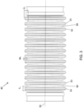
FIG. 2 , thethird section 42 includesribs 50 andchannels 54 between eachadjacent rib 50. Eachrib 50 may move (e.g., flex or bend) about anaxis 56 relative to theother ribs 50 by approximately the width of achannel 54. In the illustrated embodiment, eachrib 50 extends around an entire circumference of thethird section 42, and defines a circular cross-section (i.e., therib 50 is substantially the same distance from a center of thethird section 42 along the entire circumference). Eachrib 50 is identical to theother ribs 50. - As shown in
FIG. 3 , eachrib 50 includes a first thickness T1, and eachchannel 54 includes a first width W1. Eachrib 50 also includes a first depth D1, measured from a top of onerib 50 to a bottom of anadjacent channel 54. In the illustrated embodiment, the first thickness T1, the first width W1, and the first depth D1 are the same for everyrib 50 on opposing sides (e.g., a top and a bottom 180° apart) of thethird section 42. - As shown in
FIG. 4 , eachrib 50 also includes a second thickness T2, and eachchannel 54 also includes a second width W2. Eachrib 50 also includes a second depth D2, measured from the top of onerib 50 to a bottom of anadjacent channel 54. In the illustrated embodiment, the second thickness T2, the second width W2, and the second depth D2 are the same for everyrib 50 on opposing sides (e.g., a left side and a right side 180° apart) of thethird section 42. The second thickness T2, the second width W2, and the second depth D2 are also approximately orthogonal with respect to the first thickness T1, the first width W1, and the first depth D1. - As shown in
FIGS. 3 and4 , the first thicknesses T1 of theribs 50 are aligned with one another and the second thicknesses T2 of theribs 50 are aligned with one other. The first thickness T1 is greater than the second thickness T2, and theribs 50 taper between the first and second thicknesses T1, T2. In other words, a portion of theribs 50 on the top and bottom of thethird section 42 is thicker than a portion of theribs 50 on the left and right sides of thethird section 42. The second width W2 is also greater than the first width W1. The channels 54 (i.e., the space between adjacent ribs 50) are narrower on the top and bottom of thethird section 42 than on the left and right sides in order to provide space for the increased thickness (e.g., thethird section 42 has an elliptical cross-section). Additionally, the first depth D1 is greater than the second depth D2. Surfaces of thechannels 54 on the top and bottom are disposed closer to a center of thethird section 42 than surfaces of thechannels 54 on the left and right sides. This allows for the same angle between an upper surface of theribs 50 and thechannel 54 along the entire circumference of thethird section 42, while also allowing therib 50 to have a varying thickness around a circumference of thetube 30. - The
third section 42 may move in a given direction (e.g., a first direction, a second direction, a third direction, or a fourth direction) based on the thickness of theribs 50 and the width of thechannel 54. The first and second directions are opposite one another (e.g., up and down) and the third and fourth directions are opposite one another (e.g., left and right). The first, second, third, and fourth directions may also be orthogonal with respect toaxis 56 of thetube 30. The larger first thickness T1 and smaller first width W1 along the upper and lower sides of thethird section 42 allows for less movement in the first and second directions than is allowed in the third and fourth directions (i.e., where the second thickness T2 is smaller and the second width W2 is larger). In other words, more movement of thethird section 42 is possible in the third and fourth directions (i.e., left-right direction as shown in the figures) than in the first and second directions (i.e., up-down direction as shown in the figures). Thethird section 42 may also move in an infinite number of directions between the adjacent first, second, third, and fourth directions (e.g., thethird section 42 may move in a direction between the first and third directions). The amount of movement permitted by theribs 50 in a direction between two orthogonal directions (e.g., between the first and third directions) is greater than the amount of movement permitted in the first and second directions, but less than the amount of movement permitted in the third and fourth directions. - When using the
backpack blower 10, the user may move thejoystick 46 in order to move thesecond section 38 of theoutlet tube 30 and change the direction of the exhausted air (e.g., to change where debris is blown) out of theoutlet opening 40. The larger second width W2 of thechannels 54 along the sides of thethird section 42 allow a user to make larger adjustments to a blowout direction (i.e., direction of the exhausted air) in a horizontal direction than in a vertical direction. Arib 50 can continue to move relative to theother ribs 50 until it contacts anadjacent rib 50. The larger width W2 means that there is more space betweenadjacent ribs 50, which allows for more movement. - When a user releases the joystick 46 (i.e., and no longer supports the outlet tube 30), gravity moves the
outlet tube 30 toward the ground. The smaller first width W1 allows for minimal movement in the vertical direction. This keeps the second andthird sections outlet tube 30 from contacting the ground when the user is no longer holding thejoystick 46 and opposing the force of gravity. In the illustrated embodiment, thefirst section 34 is rotatably coupled to themain body 14, and can rotate to make larger adjustments to the vertical component of the blowout direction. - The embodiment(s) described above and illustrated in the figures are presented by way of example only and are not intended as a limitation upon the concepts and principles of the present disclosure. As such, it will be appreciated that variations and modifications to the elements and their configurations and/or arrangement exist within the spirit and scope of one or more independent aspects as described.
According to an advantageous example, a corrugated tube for a blower comprises: - a first rib extending from a surface of the corrugated tube, the first rib tapering between a first thickness and a second thickness;
- a second rib extending from the surface of the corrugated tube and being spaced apart from the first rib, the second rib tapering between the first thickness and the second thickness; and
- a channel positioned between the first rib and the second rib, the channel having a first width between adjacent first thicknesses and a second width between adjacent second thicknesses, the first width being less than the second width.
- a main body having an inlet and an outlet; and
- an outlet tube coupled to the main body proximate the outlet, the outlet tube having a circular cross section and including
- a first section, and
a second section having a first rib and a second rib, each of the first rib and the second rib tapering between a first thickness and a second thickness. - a main body; and
- an outlet tube coupled to the main body, the outlet tube including
- a first section movably coupled to the main body, and
- a second section having a first rib and a second rib, each of the first rib and the second rib tapering between a first thickness and a second thickness, the first rib movable relative to the second rib in order to move the second section relative to the first section.
In the corrugated tube of the first example, the first rib may be bendable in a first direction relative to the second rib a first distance about the first width of the channel, and may be bendable a second distance about the second width of the channel in a second direction, the first distance being less than the second distance.
In the corrugated tube of the first example, the first rib may have a first depth measured from a top of the first rib to the channel proximate the first width and the a second depth may be measured the top of the first rib to the channel proximate the second width, the first depth being greater than the second depth.
In the corrugated tube of the first example, the first rib and the second rib may be two of a plurality of ribs, each of which may be identical to one another.
In the corrugated tube of the first example, the first rib may be bendable relative to the second rib about the channel in an infinite number of radial directions.
According to a second example, a blower may comprise:
The blower of the second example may further comprise a channel positioned between the first rib and the second rib, the channel having a first width between adjacent first thicknesses and a second width between adjacent second thicknesses, the first width being less than the second width.
In the blower of the second example the first rib may be bendable relative to the second rib a first distance about the first width of the channel in a first direction, and a second distance about the second width of the channel in a second direction, the first distance being less than the second distance.
In the blower of the second example the first thickness of the first rib may be aligned with the first thickness of the second rib, and the second thickness of the first rib may be aligned with the second thickness of the second rib, wherein the first thicknesses are spaced 90° apart from the second thicknesses.
In the blower of the second example the first section may be moveable relative to the main body and the second section is moveable relative to the first section.
In the blower of the second example the outlet tube may further comprise a third section including a tube outlet, the third section coupled between the first and second section, and the third section movable with the second section relative to the first section in order to change a direction of the tube outlet.
According to a third advantageous example, a blower may comprise:
The blower of the third example may further comprise a channel positioned between the first rib and the second rib, the channel having a first width between adjacent first thicknesses and a second width between adjacent second thicknesses, the first width being less than the second width.
In the blower of the third example the first rib may be bendable relative to the second rib a first distance about the first width of the channel in a first direction, and a second distance about the second width of the channel in a second direction, the first distance being less than the second distance, and the first section being movable in the first direction a third distance that is greater than the first distance.
In the blower of the third example the first thickness may be orthogonal with respect to the second thickness.
In the blower of the third example the first rib may have a first depth measured from a top of the first rib to a channel between the first and second ribs and the a second depth measured the top of the first rib to the channel, the first depth may be proximate the first thickness and the second depth is proximate the second thickness, the first depth may be greater than the second depth.
In the blower of the third example the first rib may be bendable relative to the second rib about the channel in an infinite number of radial directions.
Claims (15)
- A corrugated tube (30) for a blower (10), the corrugated tube (30) comprising:a first rib (50) extending from a surface of the corrugated tube, the first rib extending around an entire circumference of the corrugated tube and defining a circular cross-section;a second rib (50) extending from the surface of the corrugated tube and being spaced apart from the first rib, the second rib extending around the entire circumference of the corrugated tube and defining a circular cross-section; anda channel (54) defined at a valley positioned between the first rib and the second rib and defining an elliptical cross-section about the corrugated tube, the channel having a first depth (D1) at a top of the corrugated and a second depth (D2) at a right side of the corrugated tube, the first depth being greater than the second depth.
- The corrugated tube (30) of claim 1, wherein the first depth (D1) is further defined at a bottom of the corrugated tube, and wherein the second depth (D2) is further defined at a left side of the corrugated tube.
- The corrugated tube (30) of claim 1, wherein the channel has a first width (W1) between the first and second ribs at the top of the corrugated tube and a second width (W2) between the first and second ribs at the right side of the corrugated tube, the first width being less than the second width.
- The corrugated tube (30) of claim 3, wherein the first rib (50) is bendable in a first direction relative to the second rib (50) a first distance about the first width (W1) of the channel (54), and is bendable a second distance about the second width (W2) of the channel in a second direction, the first distance being less than the second distance.
- The corrugated tube (30) of claim 1:
wherein the first rib (50) and the second rib (50) are two of a plurality of ribs, each of which are identical to one another. - The corrugated tube (30) of claim 1:
wherein the first rib is bendable relative to the second rib about the channel (54) in an infinite number of radial directions. - A blower (10) comprising:a main body (14) having an inlet and an outlet; andthe corrugated tube (30) of claim 1 coupled to the main body proximate the outlet, the corrugated tube having a circular cross section and includinga first section (34), anda second section (42) having the first rib (50) and the second rib (50).
- The blower (10) of claim 7, further comprising a battery (22) removably coupled to the main body (14).
- The blower (10) of claim 7, wherein the circumferential position of the first depth is spaced 90° apart from the circumferential position of the second depth.
- The blower (10) of claim 7:
wherein the first section (34) is moveable relative to the main body (14) and the second section (42) is moveable relative to the first section. - The blower (10) of claim 7:
wherein the corrugated tube (30) further comprises a third section including a tube outlet (40), the third section coupled between the first and second section, and the third section movable with the second section relative to the first section in order to change a direction of the tube outlet. - The blower (10) of claim 7:
wherein the corrugated tube (30) is movable in first and second opposite directions, and the corrugated tube (30) is movable in third and fourth opposite directions, the first and second opposite directions being orthogonal to the third and fourth opposite directions, and wherein the second section allows for less movement in the first and second opposite directions than is allowed in the third and fourth opposite directions. - The corrugated tube (30) of claim 7, wherein the first depth (D1) is further defined at a bottom of the corrugated tube, and wherein the second depth (D2) is further defined at a left side of the corrugated tube.
- The corrugated tube (30) of claim 7, wherein the channel has a first width (W1) between the first and second ribs at the top of the corrugated tube and a second width (W2) between the first and second ribs at the right side of the corrugated tube, the first width being less than the second width.
- The corrugated tube (30) of claim 14, wherein the first rib (50) is bendable in a first direction relative to the second rib (50) a first distance about the first width (W1) of the channel (54), and is bendable a second distance about the second width (W2) of the channel in a second direction, the first distance being less than the second distance.
Applications Claiming Priority (3)
| Application Number | Priority Date | Filing Date | Title |
|---|---|---|---|
| CN201920977937.2U CN210686430U (en) | 2019-06-26 | 2019-06-26 | Bellows for a blower and blower |
| PCT/US2020/039814 WO2020264290A1 (en) | 2019-06-26 | 2020-06-26 | Corrugated tube for blower and blower |
| EP20833544.8A EP3989711B1 (en) | 2019-06-26 | 2020-06-26 | Corrugated tube for blower and blower |
Related Parent Applications (2)
| Application Number | Title | Priority Date | Filing Date |
|---|---|---|---|
| EP20833544.8A Division EP3989711B1 (en) | 2019-06-26 | 2020-06-26 | Corrugated tube for blower and blower |
| EP20833544.8A Division-Into EP3989711B1 (en) | 2019-06-26 | 2020-06-26 | Corrugated tube for blower and blower |
Publications (2)
| Publication Number | Publication Date |
|---|---|
| EP4579112A2 true EP4579112A2 (en) | 2025-07-02 |
| EP4579112A3 EP4579112A3 (en) | 2025-09-03 |
Family
ID=70902486
Family Applications (2)
| Application Number | Title | Priority Date | Filing Date |
|---|---|---|---|
| EP20833544.8A Active EP3989711B1 (en) | 2019-06-26 | 2020-06-26 | Corrugated tube for blower and blower |
| EP25169527.6A Pending EP4579112A3 (en) | 2019-06-26 | 2020-06-26 | Corrugated tube for blower and blower |
Family Applications Before (1)
| Application Number | Title | Priority Date | Filing Date |
|---|---|---|---|
| EP20833544.8A Active EP3989711B1 (en) | 2019-06-26 | 2020-06-26 | Corrugated tube for blower and blower |
Country Status (4)
| Country | Link |
|---|---|
| US (1) | US11927282B2 (en) |
| EP (2) | EP3989711B1 (en) |
| CN (1) | CN210686430U (en) |
| WO (1) | WO2020264290A1 (en) |
Families Citing this family (1)
| Publication number | Priority date | Publication date | Assignee | Title |
|---|---|---|---|---|
| JP1719715S (en) * | 2022-01-13 | 2022-07-13 | Backpack type electric blower body |
Family Cites Families (22)
| Publication number | Priority date | Publication date | Assignee | Title |
|---|---|---|---|---|
| US5564472A (en) | 1994-01-10 | 1996-10-15 | Handy And Harman Automotive Group, Inc. | Reinforced flexible corrugated tubing |
| US20020017331A1 (en) * | 2000-06-30 | 2002-02-14 | Renaud Michel C. | Variable stiffness bellows |
| DE20319704U1 (en) * | 2003-12-19 | 2004-04-01 | Iwka Balg- Und Kompensatoren-Technologie Gmbh | Flexible pipe element with special bellows shaft geometry to improve its buckling behavior |
| ITNU20050001U1 (en) | 2005-01-10 | 2006-07-11 | Amatori S R L | FIRE-FIGHTING EQUIPMENT AGAINST WOODEN FIRE |
| DE102005053390A1 (en) | 2005-11-09 | 2007-05-10 | Volkswagen Ag | Thermoplastic corrugated water feed tube for automotive windscreen washer has stretchable end-section |
| KR100792353B1 (en) * | 2006-07-19 | 2008-01-09 | 정상덕 | Synthetic resin double pipe, its manufacturing apparatus and method |
| US20080092976A1 (en) * | 2006-10-20 | 2008-04-24 | Komatsu Zenoah Co. | Blower duct |
| JP5146165B2 (en) * | 2007-07-11 | 2013-02-20 | 住友電装株式会社 | Corrugated tube |
| JP2011127541A (en) * | 2009-12-18 | 2011-06-30 | Makita Corp | Back carrying type operating tool |
| US9332694B2 (en) * | 2011-03-18 | 2016-05-10 | Andreas Stihl Ag & Co. Kg | Blower apparatus |
| US8549699B1 (en) * | 2012-03-23 | 2013-10-08 | Francisco A. Domingo | Illuminated leaf blower |
| US9883634B2 (en) * | 2012-09-13 | 2018-02-06 | Franco Romito | Attachment for air blower |
| JP5987212B2 (en) * | 2012-12-25 | 2016-09-07 | 矢崎総業株式会社 | Wire harness |
| JP6165588B2 (en) * | 2013-10-25 | 2017-07-19 | 株式会社マキタ | Working machine |
| TWI689669B (en) * | 2014-09-18 | 2020-04-01 | 德商伊格斯公司 | Line guide device, in particular for clean room applications, shell portions and support rib structure for same |
| US20160108924A1 (en) * | 2014-10-17 | 2016-04-21 | Mean Green Products, LLC | Battery-powered, low-noise backpack blower |
| US9907234B2 (en) * | 2014-11-20 | 2018-03-06 | Black & Decker, Inc. | Battery-powered backpack blower |
| DE102015112272B4 (en) * | 2015-07-27 | 2020-12-17 | Schlemmer Gmbh | Foldable corrugated hose, cable harness and method for producing such a hinged corrugated hose |
| WO2017143922A1 (en) * | 2016-02-22 | 2017-08-31 | 常州格力博有限公司 | Piggyback working appliance, piggyback blower, and control handle assembly |
| CN106270066B (en) * | 2016-10-28 | 2018-12-28 | 燕山大学 | A kind of waveform parameters corrugated flexible metal tube and the manufacturing process such as not |
| US20180243126A1 (en) * | 2017-02-28 | 2018-08-30 | Simple Solutions Inc. | Portable blower for supplying ventilation to wounds |
| CN109630773B (en) | 2018-12-29 | 2020-01-21 | 燕山大学 | A kind of cam-shaped corrugated metal hose and forming method |
-
2019
- 2019-06-26 CN CN201920977937.2U patent/CN210686430U/en active Active
-
2020
- 2020-06-26 EP EP20833544.8A patent/EP3989711B1/en active Active
- 2020-06-26 WO PCT/US2020/039814 patent/WO2020264290A1/en not_active Ceased
- 2020-06-26 EP EP25169527.6A patent/EP4579112A3/en active Pending
- 2020-06-26 US US17/621,009 patent/US11927282B2/en active Active
Also Published As
| Publication number | Publication date |
|---|---|
| US11927282B2 (en) | 2024-03-12 |
| CN210686430U (en) | 2020-06-05 |
| EP4579112A3 (en) | 2025-09-03 |
| WO2020264290A1 (en) | 2020-12-30 |
| EP3989711B1 (en) | 2025-11-26 |
| EP3989711A1 (en) | 2022-05-04 |
| EP3989711A4 (en) | 2023-04-26 |
| US20220325830A1 (en) | 2022-10-13 |
Similar Documents
| Publication | Publication Date | Title |
|---|---|---|
| US10736403B2 (en) | Back-mounted power tool systems and methods of use | |
| US12082535B2 (en) | Axial-fan blower | |
| CN108291375B (en) | Portable Electric Blower with Low Reaction Torque | |
| US10980193B2 (en) | Piggyback working appliance, piggyback blower, and control handle assembly | |
| US9387578B2 (en) | Handle arrangement for sander | |
| US9192222B2 (en) | Backpack work machine | |
| EP3491990B1 (en) | Electric cleaner | |
| US10330116B2 (en) | Noise reduction system for a blower | |
| CN106231970A (en) | Has perforated aerator | |
| JP2011183465A (en) | Hand-holding type cutting tool | |
| CN104416549A (en) | Pole-attached power tool system | |
| US11927282B2 (en) | Corrugated tube for blower and blower | |
| EP3468438A1 (en) | Battery-operated vacuum cleaner | |
| WO2019109278A1 (en) | Blower with improved balance and construction | |
| CN106192836A (en) | Backpack blower fan system | |
| JP2016039858A (en) | Handy cleaner | |
| JP5977386B2 (en) | Battery powered power tools | |
| CN213926034U (en) | Blower fan | |
| CA2929011C (en) | Back-mounted power tool systems and methods of use | |
| US20260028993A1 (en) | Flex-mounted power tool with backpack support | |
| JP2016135540A (en) | Hand-held cutting tool | |
| JP2020138274A (en) | Portable band saw | |
| JP2010117028A (en) | Power transfer structure in pipe, and hair clipper type reaper equipped with the power transfer structure | |
| JP2013005946A (en) | Vacuum cleaner | |
| WO2015180750A1 (en) | Tube connection for blower/vacuum device |
Legal Events
| Date | Code | Title | Description |
|---|---|---|---|
| PUAI | Public reference made under article 153(3) epc to a published international application that has entered the european phase |
Free format text: ORIGINAL CODE: 0009012 |
|
| STAA | Information on the status of an ep patent application or granted ep patent |
Free format text: STATUS: THE APPLICATION HAS BEEN PUBLISHED |
|
| AC | Divisional application: reference to earlier application |
Ref document number: 3989711 Country of ref document: EP Kind code of ref document: P |
|
| AK | Designated contracting states |
Kind code of ref document: A2 Designated state(s): AL AT BE BG CH CY CZ DE DK EE ES FI FR GB GR HR HU IE IS IT LI LT LU LV MC MK MT NL NO PL PT RO RS SE SI SK SM TR |
|
| PUAL | Search report despatched |
Free format text: ORIGINAL CODE: 0009013 |
|
| AK | Designated contracting states |
Kind code of ref document: A3 Designated state(s): AL AT BE BG CH CY CZ DE DK EE ES FI FR GB GR HR HU IE IS IT LI LT LU LV MC MK MT NL NO PL PT RO RS SE SI SK SM TR |
|
| RIC1 | Information provided on ipc code assigned before grant |
Ipc: F16L 11/15 20060101AFI20250725BHEP |
|
| STAA | Information on the status of an ep patent application or granted ep patent |
Free format text: STATUS: REQUEST FOR EXAMINATION WAS MADE |
|
| 17P | Request for examination filed |
Effective date: 20260217 |
|
| STAA | Information on the status of an ep patent application or granted ep patent |
Free format text: STATUS: EXAMINATION IS IN PROGRESS |
|
| 17Q | First examination report despatched |
Effective date: 20260617 |