EP4579109A1 - Electrically driven valve - Google Patents
Electrically driven valve Download PDFInfo
- Publication number
- EP4579109A1 EP4579109A1 EP24209475.3A EP24209475A EP4579109A1 EP 4579109 A1 EP4579109 A1 EP 4579109A1 EP 24209475 A EP24209475 A EP 24209475A EP 4579109 A1 EP4579109 A1 EP 4579109A1
- Authority
- EP
- European Patent Office
- Prior art keywords
- valve
- shaft
- electrically driven
- main body
- valve element
- Prior art date
- Legal status (The legal status is an assumption and is not a legal conclusion. Google has not performed a legal analysis and makes no representation as to the accuracy of the status listed.)
- Granted
Links
Images



Classifications
-
- F—MECHANICAL ENGINEERING; LIGHTING; HEATING; WEAPONS; BLASTING
- F16—ENGINEERING ELEMENTS AND UNITS; GENERAL MEASURES FOR PRODUCING AND MAINTAINING EFFECTIVE FUNCTIONING OF MACHINES OR INSTALLATIONS; THERMAL INSULATION IN GENERAL
- F16K—VALVES; TAPS; COCKS; ACTUATING-FLOATS; DEVICES FOR VENTING OR AERATING
- F16K1/00—Lift valves or globe valves, i.e. cut-off apparatus with closure members having at least a component of their opening and closing motion perpendicular to the closing faces
- F16K1/32—Details
- F16K1/34—Cutting-off parts, e.g. valve members, seats
- F16K1/44—Details of seats or valve members of double-seat valves
- F16K1/443—Details of seats or valve members of double-seat valves the seats being in series
-
- F—MECHANICAL ENGINEERING; LIGHTING; HEATING; WEAPONS; BLASTING
- F16—ENGINEERING ELEMENTS AND UNITS; GENERAL MEASURES FOR PRODUCING AND MAINTAINING EFFECTIVE FUNCTIONING OF MACHINES OR INSTALLATIONS; THERMAL INSULATION IN GENERAL
- F16K—VALVES; TAPS; COCKS; ACTUATING-FLOATS; DEVICES FOR VENTING OR AERATING
- F16K1/00—Lift valves or globe valves, i.e. cut-off apparatus with closure members having at least a component of their opening and closing motion perpendicular to the closing faces
- F16K1/32—Details
- F16K1/34—Cutting-off parts, e.g. valve members, seats
- F16K1/36—Valve members
-
- F—MECHANICAL ENGINEERING; LIGHTING; HEATING; WEAPONS; BLASTING
- F16—ENGINEERING ELEMENTS AND UNITS; GENERAL MEASURES FOR PRODUCING AND MAINTAINING EFFECTIVE FUNCTIONING OF MACHINES OR INSTALLATIONS; THERMAL INSULATION IN GENERAL
- F16K—VALVES; TAPS; COCKS; ACTUATING-FLOATS; DEVICES FOR VENTING OR AERATING
- F16K1/00—Lift valves or globe valves, i.e. cut-off apparatus with closure members having at least a component of their opening and closing motion perpendicular to the closing faces
-
- F—MECHANICAL ENGINEERING; LIGHTING; HEATING; WEAPONS; BLASTING
- F16—ENGINEERING ELEMENTS AND UNITS; GENERAL MEASURES FOR PRODUCING AND MAINTAINING EFFECTIVE FUNCTIONING OF MACHINES OR INSTALLATIONS; THERMAL INSULATION IN GENERAL
- F16K—VALVES; TAPS; COCKS; ACTUATING-FLOATS; DEVICES FOR VENTING OR AERATING
- F16K1/00—Lift valves or globe valves, i.e. cut-off apparatus with closure members having at least a component of their opening and closing motion perpendicular to the closing faces
- F16K1/32—Details
-
- F—MECHANICAL ENGINEERING; LIGHTING; HEATING; WEAPONS; BLASTING
- F16—ENGINEERING ELEMENTS AND UNITS; GENERAL MEASURES FOR PRODUCING AND MAINTAINING EFFECTIVE FUNCTIONING OF MACHINES OR INSTALLATIONS; THERMAL INSULATION IN GENERAL
- F16K—VALVES; TAPS; COCKS; ACTUATING-FLOATS; DEVICES FOR VENTING OR AERATING
- F16K31/00—Actuating devices; Operating means; Releasing devices
- F16K31/02—Actuating devices; Operating means; Releasing devices electric; magnetic
- F16K31/04—Actuating devices; Operating means; Releasing devices electric; magnetic using a motor
-
- F—MECHANICAL ENGINEERING; LIGHTING; HEATING; WEAPONS; BLASTING
- F16—ENGINEERING ELEMENTS AND UNITS; GENERAL MEASURES FOR PRODUCING AND MAINTAINING EFFECTIVE FUNCTIONING OF MACHINES OR INSTALLATIONS; THERMAL INSULATION IN GENERAL
- F16K—VALVES; TAPS; COCKS; ACTUATING-FLOATS; DEVICES FOR VENTING OR AERATING
- F16K31/00—Actuating devices; Operating means; Releasing devices
- F16K31/02—Actuating devices; Operating means; Releasing devices electric; magnetic
- F16K31/04—Actuating devices; Operating means; Releasing devices electric; magnetic using a motor
- F16K31/047—Actuating devices; Operating means; Releasing devices electric; magnetic using a motor characterised by mechanical means between the motor and the valve, e.g. lost motion means reducing backlash, clutches, brakes or return means
-
- F—MECHANICAL ENGINEERING; LIGHTING; HEATING; WEAPONS; BLASTING
- F16—ENGINEERING ELEMENTS AND UNITS; GENERAL MEASURES FOR PRODUCING AND MAINTAINING EFFECTIVE FUNCTIONING OF MACHINES OR INSTALLATIONS; THERMAL INSULATION IN GENERAL
- F16K—VALVES; TAPS; COCKS; ACTUATING-FLOATS; DEVICES FOR VENTING OR AERATING
- F16K31/00—Actuating devices; Operating means; Releasing devices
- F16K31/44—Mechanical actuating means
- F16K31/50—Mechanical actuating means with screw-spindle or internally threaded actuating means
-
- F—MECHANICAL ENGINEERING; LIGHTING; HEATING; WEAPONS; BLASTING
- F16—ENGINEERING ELEMENTS AND UNITS; GENERAL MEASURES FOR PRODUCING AND MAINTAINING EFFECTIVE FUNCTIONING OF MACHINES OR INSTALLATIONS; THERMAL INSULATION IN GENERAL
- F16K—VALVES; TAPS; COCKS; ACTUATING-FLOATS; DEVICES FOR VENTING OR AERATING
- F16K31/00—Actuating devices; Operating means; Releasing devices
- F16K31/44—Mechanical actuating means
- F16K31/53—Mechanical actuating means with toothed gearing
-
- H—ELECTRICITY
- H02—GENERATION; CONVERSION OR DISTRIBUTION OF ELECTRIC POWER
- H02K—DYNAMO-ELECTRIC MACHINES
- H02K7/00—Arrangements for handling mechanical energy structurally associated with dynamo-electric machines, e.g. structural association with mechanical driving motors or auxiliary dynamo-electric machines
- H02K7/06—Means for converting reciprocating motion into rotary motion or vice versa
-
- H—ELECTRICITY
- H02—GENERATION; CONVERSION OR DISTRIBUTION OF ELECTRIC POWER
- H02K—DYNAMO-ELECTRIC MACHINES
- H02K7/00—Arrangements for handling mechanical energy structurally associated with dynamo-electric machines, e.g. structural association with mechanical driving motors or auxiliary dynamo-electric machines
- H02K7/10—Structural association with clutches, brakes, gears, pulleys or mechanical starters
- H02K7/116—Structural association with clutches, brakes, gears, pulleys or mechanical starters with gears
-
- F—MECHANICAL ENGINEERING; LIGHTING; HEATING; WEAPONS; BLASTING
- F16—ENGINEERING ELEMENTS AND UNITS; GENERAL MEASURES FOR PRODUCING AND MAINTAINING EFFECTIVE FUNCTIONING OF MACHINES OR INSTALLATIONS; THERMAL INSULATION IN GENERAL
- F16H—GEARING
- F16H1/00—Toothed gearings for conveying rotary motion
- F16H1/28—Toothed gearings for conveying rotary motion with gears having orbital motion
- F16H2001/2881—Toothed gearings for conveying rotary motion with gears having orbital motion comprising two axially spaced central gears, i.e. ring or sun gear, engaged by at least one common orbital gear wherein one of the central gears is forming the output
-
- F—MECHANICAL ENGINEERING; LIGHTING; HEATING; WEAPONS; BLASTING
- F16—ENGINEERING ELEMENTS AND UNITS; GENERAL MEASURES FOR PRODUCING AND MAINTAINING EFFECTIVE FUNCTIONING OF MACHINES OR INSTALLATIONS; THERMAL INSULATION IN GENERAL
- F16H—GEARING
- F16H25/00—Gearings comprising primarily only cams, cam-followers and screw-and-nut mechanisms
- F16H25/18—Gearings comprising primarily only cams, cam-followers and screw-and-nut mechanisms for conveying or interconverting oscillating or reciprocating motions
- F16H25/20—Screw mechanisms
- F16H2025/2062—Arrangements for driving the actuator
- F16H2025/2075—Coaxial drive motors
-
- F—MECHANICAL ENGINEERING; LIGHTING; HEATING; WEAPONS; BLASTING
- F16—ENGINEERING ELEMENTS AND UNITS; GENERAL MEASURES FOR PRODUCING AND MAINTAINING EFFECTIVE FUNCTIONING OF MACHINES OR INSTALLATIONS; THERMAL INSULATION IN GENERAL
- F16H—GEARING
- F16H25/00—Gearings comprising primarily only cams, cam-followers and screw-and-nut mechanisms
- F16H25/18—Gearings comprising primarily only cams, cam-followers and screw-and-nut mechanisms for conveying or interconverting oscillating or reciprocating motions
- F16H25/20—Screw mechanisms
- F16H2025/2062—Arrangements for driving the actuator
- F16H2025/2087—Arrangements for driving the actuator using planetary gears
-
- F—MECHANICAL ENGINEERING; LIGHTING; HEATING; WEAPONS; BLASTING
- F25—REFRIGERATION OR COOLING; COMBINED HEATING AND REFRIGERATION SYSTEMS; HEAT PUMP SYSTEMS; MANUFACTURE OR STORAGE OF ICE; LIQUEFACTION SOLIDIFICATION OF GASES
- F25B—REFRIGERATION MACHINES, PLANTS OR SYSTEMS; COMBINED HEATING AND REFRIGERATION SYSTEMS; HEAT PUMP SYSTEMS
- F25B41/00—Fluid-circulation arrangements
- F25B41/30—Expansion means; Dispositions thereof
- F25B41/31—Expansion valves
- F25B41/34—Expansion valves with the valve member being actuated by electric means, e.g. by piezoelectric actuators
- F25B41/35—Expansion valves with the valve member being actuated by electric means, e.g. by piezoelectric actuators by rotary motors, e.g. by stepping motors
Definitions
- the present invention relates to an electrically driven valve.
- the electrically driven valve 1 is composed of a valve main body 2 having a valve seat 2a formed in an interior of a valve chamber VC, a can 3 made of metal having a cylindrical shape with a top that is fixed to the valve main body 2 via an annular body 31, a stepping motor composed of a stator (not shown) mounted to an outer side of the can 3 and a rotor 57 disposed on an inner side of the can 3, a reduction mechanism 6 that reduces a rotational torque of the rotor 57 and transmits the same, a valve element unit 40 that is arranged within the valve chamber VC, and that comes into contact with or moves away from the valve seat 2a to control a passage amount of fluid, and a screw driving member, i.e., driving portion, 22 that converts a rotary motion of an output gear of the reduction mechanism 6 through a screw feeding mechanism, i.e., conversion mechanism, 27 into a rectilinear motion, and drives the valve element unit 40.
- a screw driving member i.e
- a compression coil spring 26 is arranged in a compressed state by having its lower end in contact with a stepped portion between the diameter expansion portion 19a and the diameter reduction portion 19b and having its upper end engaged with the spring supporting member 28, according to which the valve element unit 40 is urged constantly toward a valve opening direction.
- the rectilinear motion of the screw driving member 22 is transmitted via the ball-shaped joint 25 and the spring supporting member 28 to the valve element unit 40 having an axial shape, and thereby, the valve element unit 40 is guided by the spring case 19 to move in the axis L direction.
- the valve element unit 40 is composed of the valve shaft 41 made of metal and a valve element portion 42 made of metal.
- the valve shaft 41 includes a small diameter portion 41a, and a large diameter portion 41b having a greater diameter than the small diameter portion 41a, which are arranged coaxially.
- An upper end of the small diameter portion 41a is fit by press-fitting to an inner circumference of the spring supporting member 28, and an outer circumference of the small diameter portion 41a is fit slidably to an inner circumference of the diameter reduction portion 19b.
- a recess portion 41c having a cylindrical shape is formed at a lower end, i.e., surface facing the valve seat 2a, of the large diameter portion 41b.
- a first inner circumference portion 41d that is expanded in diameter and a second inner circumference portion 41e having a greater diameter than the first inner circumference portion 41d, are formed at a lower end side of the recess portion 41c, and a thin circumference wall of the second inner circumference portion 41e constitutes a crimping portion 41f.
- the valve element portion 42 having an approximately cylindrical shape includes a first cylindrical portion 42a having an outer diameter that is smaller than the inner diameter of the recess portion 41c, a flange portion 42b having an outer diameter that is approximately equivalent to the inner diameter of the recess portion 41c, a second cylindrical portion 42c having an outer diameter that is greater than the outer diameter of the first cylindrical portion 42a, and a tapered portion 42d having a truncated cone shape that shrinks in diameter toward the downward direction, which are arranged coaxially.
- a coil spring 44 is arranged between the inner circumference of the recess portion 41c and the first cylindrical portion 42a such that an upper end thereof is in contact with a bottom surface of the recess portion 41c and a lower end thereof is in contact with an upper surface of the flange portion 42b.
- the coil spring 44 urges the valve element portion 42 downward against the bottom surface of the recess portion 41c.
- a retaining member 43 having a thin cylindrical shape is fit by press-fitting to the first inner circumference portion 41d.
- a gap is formed between the inner circumference of the retaining member 43 and the second cylindrical portion 42c of the valve element portion 42.
- the crimping portion 41f of the valve shaft 41 Before assembling the valve element unit 40, the crimping portion 41f of the valve shaft 41 has a cylindrical shape.
- the coil spring 44 is arranged around the first cylindrical portion 42a of the valve element portion 42, and while maintaining this state, the valve element portion 42 is pushed in toward the recess portion 41c of the valve shaft 41, and the retaining member 43 is further attached by press-fitting to the first inner circumference portion 41d.
- the elastic body 45 is arranged between the outer circumference of the retaining member 43 and the inner circumference of the second inner circumference portion 41e, and the lower end of the crimping portion 41f is elastically deformed toward the inner side in the radial direction, by which the valve element unit 40 is assembled.
- the elastic body 45 may be attached to the valve shaft 41 using an adhesive.
- the valve main body 2 made of metal has the valve seat 2a having an edge shape disposed at an intersecting portion between the bottom surface of the valve chamber VC and the valve port 16.
- the tapered portion 42d of the valve element portion 42 is enabled to be seated on an entire circumference of the valve seat 2a.
- the valve main body 2 includes a projection portion, i.e., contact portion, 2b having an annular shape that is arranged to surround the circumference of the valve seat 2a and that protrudes upward from the bottom surface of the valve chamber VC.
- the projection portion 2b includes a tapered inner circumference surface 2c that expands in diameter toward the upward direction, and an outer circumference surface 2d having a cylindrical shape, and wherein an upper end 2e having a radial-diameter width thereof narrowed is made to come into contact at the entire circumference with the elastic body 45 at an outer side in the radial direction, i.e., the valve chamber VC side, of the valve seat 2a.
- FIG. 5 is a flow rate characteristic diagram of the electrically driven valve according to the present embodiment, wherein a vertical axis of the graph indicates the flow rate, and a horizontal axis thereof indicates the valve opening, i.e., axial direction position of the valve shaft 41, wherein the scale of the vertical axis may differ from the actual scale. Further, according to the flow rate characteristic diagram of FIG. 5 , a schematic diagram illustrating the relative positional relationship between the valve element portion 42 and the valve seat 2a will also be illustrated.
- valve shaft 41 of the valve element unit 40 is at the lowest position, and with the coil spring 44 in the compressed state, the bottom surface of the recess portion 41c is in contact with the upper end of the valve element portion 42. Therefore, by the downward pressing force applied from the valve shaft 41, the outer circumference surface of the tapered portion 42d is seated on the valve seat 2a, and the upper end 2e of the projection portion 2b comes into contact with the lower surface of the elastic body 45. A gap is formed between the lower surface of the flange portion 42b of the valve element portion 42 and the upper end of the retaining member 43.
- the lower surface of the elastic body 45 elastically deforms moderately, such that regardless of component accuracy, a state in which the upper end 2e of the projection portion 2b is in contact with the lower surface of the elastic body 45, may be maintained in a state where the outer circumference surface of the tapered portion 42 is seated on the valve seat 2a.
- valve element portion 42 made of metal When the valve element portion 42 made of metal is seated on the valve seat 2a made of metal, a slight gap may be formed therebetween, which may cause fluid leakage. According to the present embodiment, even if a slight gap is formed in the valve closed state, between the valve element portion 42 and the valve seat 2a, a state in which the upper end 2e of the projection portion 2b is in contact with the lower surface of the elastic body 45 is maintained, such that fluid will not flow from the interior of the valve chamber VC toward the valve seat 2a. Such a state is referred to as a valve completely closed range A illustrated in FIG. 5 .
- Rotary motion of the output shaft portion 29 is converted by the screw feeding mechanism 27 into rectilinear motion, and thereby, the output shaft portion 29 is lifted in the axial direction together with the valve shaft 41 of the valve element unit 40.
- the elastic body 45 is also lifted, but as the elastic body 45 lifts, the contact portion thereof to the upper end 2e of the projection portion 2b returns from the elastically deformed state. However, while the state of contact with the upper end 2e is maintained, fluid is prevented from flowing from the valve chamber VC toward the valve port 16.
- valve element portion 42 By the lifting of the valve shaft 41, the lower end of the valve element portion 42 separates from the bottom surface of the recess portion 41c, but since the valve element portion 42 is pressed downward toward the valve shaft 41 by the coil spring 44, the seated state of the valve element portion 42 and the valve seat 2a is maintained.
- valve element portion 42 When the valve shaft 41 is lifted further, and the lower surface of the flange portion 42b of the valve element portion 42 comes into contact with the upper end of the retaining member 43, the valve element portion 42 is lifted together with the valve shaft 41.
- the valve shaft 41 When the valve shaft 41 is lifted to a second position P2, the valve element portion 42 separates from the valve seat 2a so that the boundary range B is ended, and a flow rate control range C is started.
- fluid is flown from the valve chamber VC toward the valve port 16 by a flow rate corresponding to a gap formed between the valve element portion 42 and the valve seat 2a that is determined by the axial direction position of the valve shaft 41. Therefore, movement of fluid by a predetermined flow rate between the second piping T2 and the first piping T2 is permitted.
- the rotor 57 rotates in an opposite direction, the valve shaft 41 is lowered by a reverse operation as described above, the valve element portion 42 is seated on the valve seat 2a, and thereafter, the upper end 2e of the projection portion 2b comes into contact with the lower surface of the elastic body 45, such that the valve completely closed range A may be returned.
- valve element portion 42 seated on the valve seat 2a and then having the bottom surface of the recess portion 41c come into contact with the upper end of the valve element portion 42, excessive deformation of the elastic body 45 with which the upper end 2e of the projection portion 2b comes into contact may be prevented, such that fatigue of the elastic body 45 may be suppressed, and the valve completely closed range A may be ensured stably for a long period of time. Further, even if the elastic body 45 is deformed by aging or the like, for example, flow of fluid may still be blocked as long as the elastic body 45 deforms elastically when the projection portion 2b comes into contact therewith.
- FIG. 6 is a view similar to FIG. 2 , illustrating a valve closed state of an electrically driven valve according to a modified example of a second embodiment.
- the configurations of a valve shaft 41A of a valve element unit 40A and a valve main body 2A differ, and other configurations are similar to the embodiment described above, such that detailed descriptions of similar configurations are omitted.
- the valve shaft 41A includes a projection portion 41Ag having an annular shape at a lower end thereof.
- An inner circumference surface of the projection portion 41Ag is configured by having the first inner circumference portion 41d to which the retaining member 43 is press-fit extended to the lower end, an outer circumference surface of the projection portion 41Ag is a tapered outer circumference surface 41Ah that shrinks in diameter toward the downward direction from a vicinity of the lower end, and the projection portion 41Ag includes a lower end 41Af having an annular shape.
- the valve main body 2A includes an annular groove 2Af at a bottom surface of the valve chamber VC in the circumference of the valve seat 2a.
- the elastic body 45 is arranged within the annular groove 2Af.
- the outer circumference surface of the tapered portion 42d is seated on the valve seat 2a, and the lower end 41Af of the projection portion 41Ag contacts an upper surface of the elastic body 45.
- the lower end 41Af of the projection portion 41Ag separates from the upper surface of the elastic body 45, by which the valve completely closed range A ends, and the boundary range B starts.
- the fluid within the valve chamber VC may flow past the projection portion 41Ag toward the valve seat 2a, but due to the pressing force applied by the coil spring 44, the seated state between a valve element portion 42 and the valve seat 2a is maintained.
- valve element portion 42 separates from the valve seat 2a, by which the boundary range B ends, and the flow rate control range C starts.
- the flow rate control range C fluid flows from the valve chamber VC toward the valve port 16 according to a flow rate corresponding to the gap between the valve element portion 42 and the valve seat 2a. Therefore, movement of fluid by a predetermined flow rate between the second piping T2 and the first piping T1 is permitted.
- the present invention is not limited to the embodiments described above. Various modifications of arbitrary components of the above-described embodiments are possible. Further, arbitrary components may be added to or deleted from the above-described embodiments. For example, a reduction mechanism composed of a gear set may be disposed instead of the planetary gear reduction mechanism. Further, the present invention is also applicable to an electrically driven valve without a reduction mechanism.
- An electrically driven valve including:
- the electrically driven valve according to the first to third aspects, further including a coil spring configured to urge the valve element portion to a direction toward the valve seat with respect to the valve shaft.
- valve element portion separates from the valve seat after the elastic body has been separated from the contact portion.
- valve element portion after the valve element portion has been separated from the valve seat, fluid flowing through a gap formed between the valve element portion and the valve seat is controlled according to an axial direction position of the valve shaft.
Landscapes
- Engineering & Computer Science (AREA)
- General Engineering & Computer Science (AREA)
- Mechanical Engineering (AREA)
- Power Engineering (AREA)
- Electrically Driven Valve-Operating Means (AREA)
- Lift Valve (AREA)
Abstract
Description
- The present invention relates to an electrically driven valve.
- Heretofore, electrically driven valves have been assembled in midway of piping systems for fluid, for example, and used to open or close a flow path of fluid or to control the flow rate thereof. For example, in an electrically driven valve as disclosed in
Japanese Patent Application Laid-Open Publication No. 2023-155785 - In the electrically driven valve disclosed in
Japanese Patent Application Laid-Open Publication No. 2023-155785 - As a countermeasure against this problem, it may be possible to form either one of the valve seat or the valve element of rubber, but if the material of either one these members is changed to rubber, the member may experience fatigue, i.e., volume reduction, due to heat or aging, and the gap between the valve seat and the valve element when the valve is opened may change, such that the flow rate control of fluid may be influenced, or that the flow rate control may become difficult.
- The present invention aims at solving the problems described above, and provides an electrically driven valve that may realize a highly accurate flow rate control while suppressing fluid leakage during closing of the valve.
- The electrically driven valve according to the present invention characterizes in including:
- a valve main body including a valve chamber that is configured to store a valve element unit and that is equipped with a valve seat;
- a can connected to the valve main body;
- a rotor of a motor that is driven to rotate; and
- a conversion mechanism configured to displace a driving portion in an axial direction according to a rotation angle of the rotor,
- wherein the valve element unit includes a valve shaft connected to the driving portion, and a valve element portion that is relatively movable in the axial direction with respect to the valve shaft and that comes into contact with or moves away from the valve seat, and
- wherein an elastic body is arranged on one of the valve shaft and the valve main body so as to surround a circumference of the valve seat, and a contact portion that comes into contact with or moves away from the elastic body is arranged on the other one of the valve shaft and the valve main body.
- According to the present invention, an electrically driven valve that may realize a highly accurate flow rate control while suppressing fluid leakage during closing of the valve is provided.
-
-
FIG. 1 is a vertical cross-sectional view illustrating a valve closed state of an electrically driven valve according to a first embodiment. -
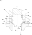
FIG. 2 is a view illustrating a periphery of a valve seat of the electrically driven valve in a valve completely closed range. -
FIG. 3 is a view illustrating a periphery of the valve seat of the electrically driven valve in a boundary range. -
FIG. 4 is a view illustrating a periphery of the valve seat of the electrically driven valve in a flow rate control range. -
FIG. 5 is a flow rate characteristic diagram of the electrically driven valve according to the first embodiment. -
FIG. 6 is a view illustrating a periphery of a valve seat of an electrically driven valve according to a second embodiment in a valve completely closed range. - Embodiments of an electrically driven valve according to the present invention will be described below with reference to the drawings. In the present specification, a rotor side is referred to as an upper side, and a valve element side is referred to as a lower side. A mechanical paradox planetary gear reduction mechanism is one type of a planetary gear reduction mechanism.
-
FIG. 1 is a vertical cross-sectional view illustrating a valve closed state of an electrically drivenvalve 1 according to a first embodiment of the present invention, andFIGs. 2 to 4 are cross-sectional views illustrating in enlarged view a periphery of a valve seat of the electrically drivenvalve 1 according to the first embodiment. The electrically drivenvalve 1 according to the present embodiment is used, for example, to adjust a refrigerant flow rate in a refrigeration cycle. An axis of the electrically drivenvalve 1 is referred to as L. - The electrically driven
valve 1 according to the present embodiment is composed of a valvemain body 2 having avalve seat 2a formed in an interior of a valve chamber VC, acan 3 made of metal having a cylindrical shape with a top that is fixed to the valvemain body 2 via anannular body 31, a stepping motor composed of a stator (not shown) mounted to an outer side of thecan 3 and arotor 57 disposed on an inner side of thecan 3, areduction mechanism 6 that reduces a rotational torque of therotor 57 and transmits the same, avalve element unit 40 that is arranged within the valve chamber VC, and that comes into contact with or moves away from thevalve seat 2a to control a passage amount of fluid, and a screw driving member, i.e., driving portion, 22 that converts a rotary motion of an output gear of thereduction mechanism 6 through a screw feeding mechanism, i.e., conversion mechanism, 27 into a rectilinear motion, and drives thevalve element unit 40. - The valve
main body 2 has avalve port 16 that is communicated with the valve chamber VC formed along an axis L, wherein a first piping T1 is connected by brazing or the like to thevalve port 16 side of the valvemain body 2, and a second piping T2 is connected by brazing or the like to be communicated with anopening 18 formed to a side surface of the valve chamber VC. An axis of the second piping T2 is referred to as O. The axis O is orthogonal to the axis L. - Further, a
screw bearing member 13 having afemale screw portion 13a formed on a lower end side at a center thereof, is inserted to an upper portion of the valve chamber VC of the valvemain body 2, and it is fixed to the valvemain body 2, by press-fitting or the like. - A
shaft support portion 81 made of resin is attached to an inner side at an upper end of thecan 3. More specifically, theshaft support portion 81 is formed by consecutively connecting acylindrical portion 81a having an upper end surface thereof in contact with a lower surface of thecan 3 with aflange portion 81b that is arranged on a circumference of thecylindrical portion 81a and that has an outer circumference thereof in contact with an inner circumference of thecan 3. A throughhole 81c that is formed to pass through in an up-down direction is formed coaxially with the axis L at a center of theshaft support portion 81. An inner diameter of thethrough hole 81c is approximately equivalent to an outer diameter of asupport shaft 8. - The
reduction mechanism 6 includes, on an inner circumference side of therotor 57, asun gear 61 that is formed integrally with arotor support member 56, afixing ring gear 62 fixed via a thintubular body 66 that is firmly fixed to an upper portion of the valvemain body 2 and that extends upward,planetary gears 63 that are arranged between thesun gear 61 and thefixing ring gear 62 and that mesh respectively therewith, acarrier 64 that supports theplanetary gears 63 in a rotatable manner, and anoutput gear member 65 having a tubular shape with a bottom having teeth that mesh with theplanetary gears 63 disposed on an inner circumference thereof, by which a mechanical paradox planetary gear reduction mechanism is composed. A number of teeth of thefixing ring gear 62 is set to differ from a number of teeth of theoutput gear member 65. - The
support shaft 8 made of metal passes through therotor support member 56 and thesun gear 61, and is retained in a manner rotatable therewith. An upper end of thesupport shaft 8 fits to the throughhole 81c of theshaft support portion 81 attached to thecan 3, and is supported in a manner movable in the rotational direction and the axis L direction. - An upper portion of an
output shaft portion 29 having a stepped cylindrical shape formed on an upper portion of thescrew driving member 22, is press-fit to a center of a bottom portion of theoutput gear member 65. A lower end of thesupport shaft 8 is fit by press-fitting to an upper opening of theoutput shaft portion 29, and theoutput gear member 65, thesupport shaft 8, and theoutput shaft portion 29 are configured to rotate integrally. - A
male screw portion 22a formed on a lower portion of thescrew driving member 22, is screwed onto thefemale screw portion 13a of thescrew bearing member 13. A rotary motion of theoutput gear member 65, that is, therotor 57, is converted into a rectilinear motion along the axis L by a screw feeding mechanism, i.e., conversion mechanism, 27 composed of themale screw portion 22a and thefemale screw portion 13a. - A
slit 29a is formed on a lower end of theoutput shaft portion 29, and ablade 22b protruding along the axis L is formed on an upper end of thescrew driving member 22, wherein theslit 29a and theblade 22b are engaged such that they may move in sliding motion against each other. Thereby, theoutput shaft portion 29 is connected to thescrew driving member 22 in an integrally rotatable manner, such that when theoutput gear member 65, i.e., therotor 57, rotates, theoutput shaft portion 29 and thescrew driving member 22 rotate integrally, and they are also relatively movable in linear motion along the axis L. - When the
output gear member 65, i.e., therotor 57, rotates, theoutput gear member 65 and thescrew driving member 22 rotate integrally, and they also move in rectilinear motion along the axis L with respect to the valvemain body 2. Along with the lifting and lowering of theoutput gear member 65, thecarrier 64 and theplanetary gears 63 placed on a bottom surface of theoutput gear member 65 are also lifted and lowered integrally with thesupport shaft 8. - A lower end of a ball-
shaped joint 25 composed of aball 23 and aball seat 24 is in contact with an upper end of aspring supporting member 28 having a hollow cylindrical shape that is press-fit coaxially to an upper end of avalve shaft 41 of thevalve element unit 40. Aspring case 19 having a tubular shape arranged in the circumference of thevalve element unit 40 and thespring supporting member 28, is composed by consecutively connecting adiameter expansion portion 19a, adiameter reduction portion 19b, and an upperend flange portion 19c that extends outward in a radial direction from the upper end of thediameter expansion portion 19a. The upperend flange portion 19c is engaged to an inner-circumference stepped portion of the valvemain body 2, and fixed and supported by thescrew bearing member 13. Thediameter reduction portion 19b retains the outer circumference of thevalve shaft 41 of thevalve element unit 40 in a slidable manner. - A
compression coil spring 26 is arranged in a compressed state by having its lower end in contact with a stepped portion between thediameter expansion portion 19a and thediameter reduction portion 19b and having its upper end engaged with thespring supporting member 28, according to which thevalve element unit 40 is urged constantly toward a valve opening direction. - The rectilinear motion of the
screw driving member 22 is transmitted via the ball-shaped joint 25 and thespring supporting member 28 to thevalve element unit 40 having an axial shape, and thereby, thevalve element unit 40 is guided by thespring case 19 to move in the axis L direction. - The
valve element unit 40 is composed of thevalve shaft 41 made of metal and avalve element portion 42 made of metal. Thevalve shaft 41 includes asmall diameter portion 41a, and alarge diameter portion 41b having a greater diameter than thesmall diameter portion 41a, which are arranged coaxially. An upper end of thesmall diameter portion 41a is fit by press-fitting to an inner circumference of thespring supporting member 28, and an outer circumference of thesmall diameter portion 41a is fit slidably to an inner circumference of thediameter reduction portion 19b. Arecess portion 41c having a cylindrical shape is formed at a lower end, i.e., surface facing thevalve seat 2a, of thelarge diameter portion 41b. - In
FIGs. 2 to 4 , a firstinner circumference portion 41d that is expanded in diameter and a secondinner circumference portion 41e having a greater diameter than the firstinner circumference portion 41d, are formed at a lower end side of therecess portion 41c, and a thin circumference wall of the secondinner circumference portion 41e constitutes acrimping portion 41f. - The
valve element portion 42 having an approximately cylindrical shape includes a firstcylindrical portion 42a having an outer diameter that is smaller than the inner diameter of therecess portion 41c, aflange portion 42b having an outer diameter that is approximately equivalent to the inner diameter of therecess portion 41c, a secondcylindrical portion 42c having an outer diameter that is greater than the outer diameter of the firstcylindrical portion 42a, and a taperedportion 42d having a truncated cone shape that shrinks in diameter toward the downward direction, which are arranged coaxially. - A
coil spring 44 is arranged between the inner circumference of therecess portion 41c and the firstcylindrical portion 42a such that an upper end thereof is in contact with a bottom surface of therecess portion 41c and a lower end thereof is in contact with an upper surface of theflange portion 42b. Thecoil spring 44 urges thevalve element portion 42 downward against the bottom surface of therecess portion 41c. - A retaining
member 43 having a thin cylindrical shape is fit by press-fitting to the firstinner circumference portion 41d. A gap is formed between the inner circumference of the retainingmember 43 and the secondcylindrical portion 42c of thevalve element portion 42. - In a state where the upper end of the retaining
member 43 is in contact with a stepped portion of the firstinner circumference portion 41d and the secondinner circumference portion 41e, an annular space is formed between an outer circumference of the retainingmember 43 and an inner circumference of the secondinner circumference portion 41e, and anelastic body 45 having an annular shape and formed of rubber or resin is disposed in this space. By elastically deforming when disposed in this space, theelastic body 45 comes into close contact with the outer circumference of the retainingmember 43 and the inner circumference of the secondinner circumference portion 41e. Materials such as HNBR and PTFE may be used to form theelastic body 45, but the materials are not limited thereto. - Before assembling the
valve element unit 40, the crimpingportion 41f of thevalve shaft 41 has a cylindrical shape. Upon assembly, thecoil spring 44 is arranged around the firstcylindrical portion 42a of thevalve element portion 42, and while maintaining this state, thevalve element portion 42 is pushed in toward therecess portion 41c of thevalve shaft 41, and the retainingmember 43 is further attached by press-fitting to the firstinner circumference portion 41d. Thereafter, theelastic body 45 is arranged between the outer circumference of the retainingmember 43 and the inner circumference of the secondinner circumference portion 41e, and the lower end of the crimpingportion 41f is elastically deformed toward the inner side in the radial direction, by which thevalve element unit 40 is assembled. Alternatively, theelastic body 45 may be attached to thevalve shaft 41 using an adhesive. - The valve
main body 2 made of metal has thevalve seat 2a having an edge shape disposed at an intersecting portion between the bottom surface of the valve chamber VC and thevalve port 16. The taperedportion 42d of thevalve element portion 42 is enabled to be seated on an entire circumference of thevalve seat 2a. - Furter, the valve
main body 2 includes a projection portion, i.e., contact portion, 2b having an annular shape that is arranged to surround the circumference of thevalve seat 2a and that protrudes upward from the bottom surface of the valve chamber VC. Theprojection portion 2b includes a taperedinner circumference surface 2c that expands in diameter toward the upward direction, and anouter circumference surface 2d having a cylindrical shape, and wherein anupper end 2e having a radial-diameter width thereof narrowed is made to come into contact at the entire circumference with theelastic body 45 at an outer side in the radial direction, i.e., the valve chamber VC side, of thevalve seat 2a. -
FIG. 5 is a flow rate characteristic diagram of the electrically driven valve according to the present embodiment, wherein a vertical axis of the graph indicates the flow rate, and a horizontal axis thereof indicates the valve opening, i.e., axial direction position of thevalve shaft 41, wherein the scale of the vertical axis may differ from the actual scale. Further, according to the flow rate characteristic diagram ofFIG. 5 , a schematic diagram illustrating the relative positional relationship between thevalve element portion 42 and thevalve seat 2a will also be illustrated. In the present embodiment, the second piping T2 side serves as a high pressure side, and the first piping T1 side serves as a low pressure side, but alternatively, the second piping T2 side may serve as the low pressure side and thefirst piping T 1 side may serve as the high pressure side. - In the state illustrated in
FIG. 2 , thevalve shaft 41 of thevalve element unit 40 is at the lowest position, and with thecoil spring 44 in the compressed state, the bottom surface of therecess portion 41c is in contact with the upper end of thevalve element portion 42. Therefore, by the downward pressing force applied from thevalve shaft 41, the outer circumference surface of the taperedportion 42d is seated on thevalve seat 2a, and theupper end 2e of theprojection portion 2b comes into contact with the lower surface of theelastic body 45. A gap is formed between the lower surface of theflange portion 42b of thevalve element portion 42 and the upper end of the retainingmember 43. - In this state, the lower surface of the
elastic body 45 elastically deforms moderately, such that regardless of component accuracy, a state in which theupper end 2e of theprojection portion 2b is in contact with the lower surface of theelastic body 45, may be maintained in a state where the outer circumference surface of the taperedportion 42 is seated on thevalve seat 2a. - When the
valve element portion 42 made of metal is seated on thevalve seat 2a made of metal, a slight gap may be formed therebetween, which may cause fluid leakage. According to the present embodiment, even if a slight gap is formed in the valve closed state, between thevalve element portion 42 and thevalve seat 2a, a state in which theupper end 2e of theprojection portion 2b is in contact with the lower surface of theelastic body 45 is maintained, such that fluid will not flow from the interior of the valve chamber VC toward thevalve seat 2a. Such a state is referred to as a valve completely closed range A illustrated inFIG. 5 . - In the valve completely closed range A, fluid is prevented from flowing from the valve chamber VC toward the
valve port 16. Therefore, movement of fluid between the second piping T2 and the first piping T1 will be limited. - By driving the
rotor 57 of the stepping motor to rotate by supplying power to the stator from the valve completely closed range A, the rotational torque of therotor 57 is transmitted via therotor support member 56 to thesun gear 61 of thereduction mechanism 6, and a rotational torque that has been reduced by a predetermined reduction ratio is output from theoutput gear member 65. The rotational torque of theoutput gear member 65 is transmitted to theoutput shaft portion 29. - Rotary motion of the
output shaft portion 29 is converted by thescrew feeding mechanism 27 into rectilinear motion, and thereby, theoutput shaft portion 29 is lifted in the axial direction together with thevalve shaft 41 of thevalve element unit 40. By the lifting of thevalve shaft 41, theelastic body 45 is also lifted, but as theelastic body 45 lifts, the contact portion thereof to theupper end 2e of theprojection portion 2b returns from the elastically deformed state. However, while the state of contact with theupper end 2e is maintained, fluid is prevented from flowing from the valve chamber VC toward thevalve port 16. - By the lifting of the
valve shaft 41, the lower end of thevalve element portion 42 separates from the bottom surface of therecess portion 41c, but since thevalve element portion 42 is pressed downward toward thevalve shaft 41 by thecoil spring 44, the seated state of thevalve element portion 42 and thevalve seat 2a is maintained. - When the
valve shaft 41 is lifted to a first position P1, as illustrated inFIG. 3 , a lower surface of theelastic body 45 separates from theupper end 2e of theprojection portion 2b, and the valve completely closed range A is ended. Thereby, the fluid within the valve chamber VC may move past theprojection portion 2b and toward thevalve seat 2a, but due to the pressing force of thecoil spring 44, the seated state between thevalve element portion 42 and thevalve seat 2a is maintained. - In this state, if there is a slight gap between the
valve element portion 42 and thevalve seat 2a, fluid is flown through the gap from the valve chamber VC side toward thevalve port 16, but the amount thereof is very little. This state is referred to as a boundary range B. - When the
valve shaft 41 is lifted further, and the lower surface of theflange portion 42b of thevalve element portion 42 comes into contact with the upper end of the retainingmember 43, thevalve element portion 42 is lifted together with thevalve shaft 41. When thevalve shaft 41 is lifted to a second position P2, thevalve element portion 42 separates from thevalve seat 2a so that the boundary range B is ended, and a flow rate control range C is started. In the flow rate control range C illustrated inFIG. 4 , fluid is flown from the valve chamber VC toward thevalve port 16 by a flow rate corresponding to a gap formed between thevalve element portion 42 and thevalve seat 2a that is determined by the axial direction position of thevalve shaft 41. Therefore, movement of fluid by a predetermined flow rate between the second piping T2 and the first piping T2 is permitted. - By supplying power with a reverse characteristic to the stator in the valve opened state, the
rotor 57 rotates in an opposite direction, thevalve shaft 41 is lowered by a reverse operation as described above, thevalve element portion 42 is seated on thevalve seat 2a, and thereafter, theupper end 2e of theprojection portion 2b comes into contact with the lower surface of theelastic body 45, such that the valve completely closed range A may be returned. - According to the present embodiment, by having the
valve element portion 42 seated on thevalve seat 2a and then having the bottom surface of therecess portion 41c come into contact with the upper end of thevalve element portion 42, excessive deformation of theelastic body 45 with which theupper end 2e of theprojection portion 2b comes into contact may be prevented, such that fatigue of theelastic body 45 may be suppressed, and the valve completely closed range A may be ensured stably for a long period of time. Further, even if theelastic body 45 is deformed by aging or the like, for example, flow of fluid may still be blocked as long as theelastic body 45 deforms elastically when theprojection portion 2b comes into contact therewith. - Further, if foreign matter is mixed in the fluid, jamming may occur between the
upper end 2e of theprojection portion 2b and theelastic body 45. In that case, since theelastic body 45 elastically deforms, fluid leakage may be prevented even if such a foreign matter is jammed between theupper end 2e and theelastic body 45. Further, since the foreign matter is washed away by fluid when theupper end 2e and theelastic body 45 are separated, foreign matter may be prevented from staying at the same place. Therefore, it may be possible to provide the electrically drivenvalve 1 that may suppress fluid leakage during closing of valve while realizing a highly accurate flow rate control. -
FIG. 6 is a view similar toFIG. 2 , illustrating a valve closed state of an electrically driven valve according to a modified example of a second embodiment. In the present embodiment, the configurations of avalve shaft 41A of avalve element unit 40A and a valvemain body 2A differ, and other configurations are similar to the embodiment described above, such that detailed descriptions of similar configurations are omitted. - The
valve shaft 41A according to the present embodiment includes a projection portion 41Ag having an annular shape at a lower end thereof. An inner circumference surface of the projection portion 41Ag is configured by having the firstinner circumference portion 41d to which the retainingmember 43 is press-fit extended to the lower end, an outer circumference surface of the projection portion 41Ag is a tapered outer circumference surface 41Ah that shrinks in diameter toward the downward direction from a vicinity of the lower end, and the projection portion 41Ag includes a lower end 41Af having an annular shape. - The valve
main body 2A includes an annular groove 2Af at a bottom surface of the valve chamber VC in the circumference of thevalve seat 2a. Theelastic body 45 is arranged within the annular groove 2Af. - According to the present embodiment, similar to the aforementioned embodiment, in the valve completely closed range A, the outer circumference surface of the tapered
portion 42d is seated on thevalve seat 2a, and the lower end 41Af of the projection portion 41Ag contacts an upper surface of theelastic body 45. - Meanwhile, when the
valve shaft 41A is lifted to the first position P1 (refer toFIG. 5 ), the lower end 41Af of the projection portion 41Ag separates from the upper surface of theelastic body 45, by which the valve completely closed range A ends, and the boundary range B starts. In the boundary range B, the fluid within the valve chamber VC may flow past the projection portion 41Ag toward thevalve seat 2a, but due to the pressing force applied by thecoil spring 44, the seated state between avalve element portion 42 and thevalve seat 2a is maintained. - Further, when the
valve shaft 41A is lifted and reaches the second position P2 (refer toFIG. 5 ), thevalve element portion 42 separates from thevalve seat 2a, by which the boundary range B ends, and the flow rate control range C starts. In the flow rate control range C, fluid flows from the valve chamber VC toward thevalve port 16 according to a flow rate corresponding to the gap between thevalve element portion 42 and thevalve seat 2a. Therefore, movement of fluid by a predetermined flow rate between the second piping T2 and the first piping T1 is permitted. - The present invention is not limited to the embodiments described above. Various modifications of arbitrary components of the above-described embodiments are possible. Further, arbitrary components may be added to or deleted from the above-described embodiments. For example, a reduction mechanism composed of a gear set may be disposed instead of the planetary gear reduction mechanism. Further, the present invention is also applicable to an electrically driven valve without a reduction mechanism.
- The present specification contains disclosure of the following inventions.
- An electrically driven valve including:
- a valve main body including a valve chamber that is configured to store a valve element unit and that is equipped with a valve seat;
- a can connected to the valve main body;
- a rotor of a motor that is driven to rotate; and
- a conversion mechanism configured to displace a driving portion in an axial direction according to a rotation angle of the rotor,
- wherein the valve element unit includes a valve shaft connected to the driving portion, and a valve element portion that is relatively movable in the axial direction with respect to the valve shaft and that comes into contact with or moves away from the valve seat, and
- wherein an elastic body is arranged on one of the valve shaft and the valve main body so as to surround a circumference of the valve seat, and a contact portion that comes into contact with or moves away from the elastic body is arranged on the other one of the valve shaft and the valve main body.
- The electrically driven valve according to the first aspect,
wherein an elastic body is arranged on the valve shaft, and a projection portion having an annular shape serving as the contact portion is formed on the valve element portion. - The electrically driven valve according to the first aspect,
wherein an elastic body is arranged on the valve main body, and a projection portion having an annular shape serving as the contact portion is formed on the valve shaft. - The electrically driven valve according to the first to third aspects, further including
a coil spring configured to urge the valve element portion to a direction toward the valve seat with respect to the valve shaft. - The electrically driven valve according to the fourth aspect,
- wherein the valve element portion is arranged within a recess portion facing the valve seat side of the valve shaft, and
- wherein a retaining member configured to prevent the valve element portion from being withdrawn from within the recess portion is disposed in the recess portion.
- The electrically driven valve according to any one of the first to fifth aspects,
wherein, in a state where the valve shaft moves to a direction separating from the valve seat, the valve element portion separates from the valve seat after the elastic body has been separated from the contact portion. - The electrically driven valve according to any one of the first to sixth aspects,
wherein, after the valve element portion has been separated from the valve seat, fluid flowing through a gap formed between the valve element portion and the valve seat is controlled according to an axial direction position of the valve shaft.
Claims (7)
- An electrically driven valve comprising:a valve main body including a valve chamber that is configured to store a valve element unit and that is equipped with a valve seat;a can connected to the valve main body;a rotor of a motor that is driven to rotate; anda conversion mechanism configured to displace a driving portion in an axial direction according to a rotation angle of the rotor,wherein the valve element unit includes a valve shaft connected to the driving portion, and a valve element portion that is relatively movable in the axial direction with respect to the valve shaft and that comes into contact with or moves away from the valve seat, andwherein an elastic body is arranged on one of the valve shaft and the valve main body so as to surround a circumference of the valve seat, and a contact portion that comes into contact with or moves away from the elastic body is arranged on the other one of the valve shaft and the valve main body.
- The electrically driven valve according to claim 1,
wherein an elastic body is arranged on the valve shaft, and a projection portion having an annular shape serving as the contact portion is formed on the valve element portion. - The electrically driven valve according to claim 1,
wherein an elastic body is arranged on the valve main body, and a projection portion having an annular shape serving as the contact portion is formed on the valve shaft. - The electrically driven valve according to claim 1, further comprising
a coil spring configured to urge the valve element portion to a direction toward the valve seat with respect to the valve shaft. - The electrically driven valve according to claim 4,wherein the valve element portion is arranged within a recess portion facing the valve seat side of the valve shaft, andwherein a retaining member configured to prevent the valve element portion from being withdrawn from within the recess portion is disposed in the recess portion.
- The electrically driven valve according to claim 1,
wherein, in a state where the valve shaft moves to a direction separating from the valve seat, the valve element portion separates from the valve seat after the elastic body has been separated from the contact portion. - The electrically driven valve according to claim 6,
wherein, after the valve element portion has been separated from the valve seat, fluid flowing through a gap formed between the valve element portion and the valve seat is controlled according to an axial direction position of the valve shaft.
Applications Claiming Priority (1)
| Application Number | Priority Date | Filing Date | Title |
|---|---|---|---|
| JP2023219060A JP7808870B2 (en) | 2023-12-26 | 2023-12-26 | Motor-operated valve |
Publications (2)
| Publication Number | Publication Date |
|---|---|
| EP4579109A1 true EP4579109A1 (en) | 2025-07-02 |
| EP4579109B1 EP4579109B1 (en) | 2026-04-08 |
Family
ID=93333566
Family Applications (1)
| Application Number | Title | Priority Date | Filing Date |
|---|---|---|---|
| EP24209475.3A Active EP4579109B1 (en) | 2023-12-26 | 2024-10-29 | Electrically driven valve |
Country Status (3)
| Country | Link |
|---|---|
| EP (1) | EP4579109B1 (en) |
| JP (1) | JP7808870B2 (en) |
| CN (1) | CN120212249A (en) |
Citations (2)
| Publication number | Priority date | Publication date | Assignee | Title |
|---|---|---|---|---|
| CN114909483A (en) * | 2022-07-15 | 2022-08-16 | 山东鑫亚格林鲍尔燃油系统有限公司 | An electronic expansion valve |
| JP2023155785A (en) | 2022-04-11 | 2023-10-23 | 株式会社不二工機 | electric valve |
Family Cites Families (4)
| Publication number | Priority date | Publication date | Assignee | Title |
|---|---|---|---|---|
| DE102004004708B3 (en) * | 2004-01-30 | 2005-04-21 | Karl Dungs Gmbh & Co. Kg | Magnetically-operated double-seat valve for shutting off fluid flow has armature moving circular seal engaging triangular-section seat and surrounding inner valve with triangular-section seal |
| JP6598153B2 (en) * | 2015-10-15 | 2019-10-30 | リンナイ株式会社 | safety valve |
| JP6902789B2 (en) * | 2018-02-20 | 2021-07-14 | 株式会社不二工機 | Electric valve |
| JP7519265B2 (en) * | 2020-10-26 | 2024-07-19 | 株式会社鷺宮製作所 | Motor-operated valve and refrigeration cycle system |
-
2023
- 2023-12-26 JP JP2023219060A patent/JP7808870B2/en active Active
-
2024
- 2024-09-26 CN CN202411349868.2A patent/CN120212249A/en active Pending
- 2024-10-29 EP EP24209475.3A patent/EP4579109B1/en active Active
Patent Citations (2)
| Publication number | Priority date | Publication date | Assignee | Title |
|---|---|---|---|---|
| JP2023155785A (en) | 2022-04-11 | 2023-10-23 | 株式会社不二工機 | electric valve |
| CN114909483A (en) * | 2022-07-15 | 2022-08-16 | 山东鑫亚格林鲍尔燃油系统有限公司 | An electronic expansion valve |
Also Published As
| Publication number | Publication date |
|---|---|
| CN120212249A (en) | 2025-06-27 |
| JP2025101948A (en) | 2025-07-08 |
| JP7808870B2 (en) | 2026-01-30 |
| EP4579109B1 (en) | 2026-04-08 |
Similar Documents
| Publication | Publication Date | Title |
|---|---|---|
| EP3273186B1 (en) | Motor-operated valve | |
| US8851448B2 (en) | Motor-operated valve | |
| JP6481155B2 (en) | Motorized valve | |
| JP2016151284A (en) | Motor valve | |
| KR20150062965A (en) | Stepping motor driven control valve | |
| EP3109526A1 (en) | Motor-driven valve | |
| EP1777447A2 (en) | Valve | |
| KR20060043634A (en) | Electric valve | |
| EP3447404A1 (en) | Control valve | |
| CN112901791A (en) | Expansion valve | |
| CN106090263A (en) | Electrodynamic valve | |
| JP7519265B2 (en) | Motor-operated valve and refrigeration cycle system | |
| CN112728122A (en) | Electric valve and refrigeration cycle system | |
| EP4579109B1 (en) | Electrically driven valve | |
| EP4180699B1 (en) | Electric valve | |
| CN108779870A (en) | Motor-driven valve and refrigerating circulation system | |
| EP4234996B1 (en) | Electric valve | |
| WO2022185824A1 (en) | Flow rate control valve | |
| CN116892624A (en) | Electric valve | |
| JP7808871B2 (en) | Motor-operated valve | |
| JP2000266194A (en) | Two-stage electric expansion valve | |
| JP2019124315A (en) | Motor-operated valve | |
| JP7835445B2 (en) | Electric valve | |
| JP7390745B2 (en) | electric valve | |
| CN116892644A (en) | Electric valve |
Legal Events
| Date | Code | Title | Description |
|---|---|---|---|
| PUAI | Public reference made under article 153(3) epc to a published international application that has entered the european phase |
Free format text: ORIGINAL CODE: 0009012 |
|
| STAA | Information on the status of an ep patent application or granted ep patent |
Free format text: STATUS: THE APPLICATION HAS BEEN PUBLISHED |
|
| AK | Designated contracting states |
Kind code of ref document: A1 Designated state(s): AL AT BE BG CH CY CZ DE DK EE ES FI FR GB GR HR HU IE IS IT LI LT LU LV MC ME MK MT NL NO PL PT RO RS SE SI SK SM TR |
|
| STAA | Information on the status of an ep patent application or granted ep patent |
Free format text: STATUS: REQUEST FOR EXAMINATION WAS MADE |
|
| 17P | Request for examination filed |
Effective date: 20250722 |
|
| GRAP | Despatch of communication of intention to grant a patent |
Free format text: ORIGINAL CODE: EPIDOSNIGR1 |
|
| STAA | Information on the status of an ep patent application or granted ep patent |
Free format text: STATUS: GRANT OF PATENT IS INTENDED |
|
| RIC1 | Information provided on ipc code assigned before grant |
Ipc: F16K 1/44 20060101AFI20251112BHEP Ipc: F16K 31/04 20060101ALI20251112BHEP Ipc: F16K 31/50 20060101ALI20251112BHEP Ipc: F16K 31/53 20060101ALI20251112BHEP Ipc: F25B 41/35 20210101ALI20251112BHEP Ipc: H02K 7/06 20060101ALI20251112BHEP Ipc: H02K 7/116 20060101ALI20251112BHEP |
|
| INTG | Intention to grant announced |
Effective date: 20251201 |
|
| GRAS | Grant fee paid |
Free format text: ORIGINAL CODE: EPIDOSNIGR3 |
|
| GRAA | (expected) grant |
Free format text: ORIGINAL CODE: 0009210 |
|
| STAA | Information on the status of an ep patent application or granted ep patent |
Free format text: STATUS: THE PATENT HAS BEEN GRANTED |
|
| AK | Designated contracting states |
Kind code of ref document: B1 Designated state(s): AL AT BE BG CH CY CZ DE DK EE ES FI FR GB GR HR HU IE IS IT LI LT LU LV MC ME MK MT NL NO PL PT RO RS SE SI SK SM TR |
|
| REG | Reference to a national code |
Ref country code: CH Ref legal event code: F10 Free format text: ST27 STATUS EVENT CODE: U-0-0-F10-F00 (AS PROVIDED BY THE NATIONAL OFFICE) Effective date: 20260408 Ref country code: GB Ref legal event code: FG4D |
|
| REG | Reference to a national code |
Ref country code: DE Ref legal event code: R096 Ref document number: 602024003834 Country of ref document: DE |