EP4579049A1 - Binding machine - Google Patents
Binding machine Download PDFInfo
- Publication number
- EP4579049A1 EP4579049A1 EP24220179.6A EP24220179A EP4579049A1 EP 4579049 A1 EP4579049 A1 EP 4579049A1 EP 24220179 A EP24220179 A EP 24220179A EP 4579049 A1 EP4579049 A1 EP 4579049A1
- Authority
- EP
- European Patent Office
- Prior art keywords
- guide
- wire
- wires
- curl
- feeding path
- Prior art date
- Legal status (The legal status is an assumption and is not a legal conclusion. Google has not performed a legal analysis and makes no representation as to the accuracy of the status listed.)
- Pending
Links
Images



Classifications
-
- E—FIXED CONSTRUCTIONS
- E04—BUILDING
- E04G—SCAFFOLDING; FORMS; SHUTTERING; BUILDING IMPLEMENTS OR AIDS, OR THEIR USE; HANDLING BUILDING MATERIALS ON THE SITE; REPAIRING, BREAKING-UP OR OTHER WORK ON EXISTING BUILDINGS
- E04G21/00—Preparing, conveying, or working-up building materials or building elements in situ; Other devices or measures for constructional work
- E04G21/12—Mounting of reinforcing inserts; Prestressing
- E04G21/122—Machines for joining reinforcing bars
- E04G21/123—Wire twisting tools
-
- B—PERFORMING OPERATIONS; TRANSPORTING
- B21—MECHANICAL METAL-WORKING WITHOUT ESSENTIALLY REMOVING MATERIAL; PUNCHING METAL
- B21F—WORKING OR PROCESSING OF METAL WIRE
- B21F15/00—Connecting wire to wire or other metallic material or objects; Connecting parts by means of wire
- B21F15/02—Connecting wire to wire or other metallic material or objects; Connecting parts by means of wire wire with wire
- B21F15/04—Connecting wire to wire or other metallic material or objects; Connecting parts by means of wire wire with wire without additional connecting elements or material, e.g. by twisting
-
- B—PERFORMING OPERATIONS; TRANSPORTING
- B25—HAND TOOLS; PORTABLE POWER-DRIVEN TOOLS; MANIPULATORS
- B25B—TOOLS OR BENCH DEVICES NOT OTHERWISE PROVIDED FOR, FOR FASTENING, CONNECTING, DISENGAGING, OR HOLDING
- B25B25/00—Implements for fastening, connecting or tensioning of wire or strip
Definitions
- Patent Literature 1 Japanese Patent No. 6791141B
- the binding machine that aligns two or more wires in parallel and feeds the wires, when one of the plurality of wires moves in a direction toward another wire in a curl guide, which curls the wires, it affects a posture of the wires in the air after being fed out from the curl guide.
- a landing position on an induction guide that guides the wires to the binding means also varies.
- the present disclosure has been made in view of the above problems, and an object thereof is to provide a binding machine that can suppress one of a plurality of wires from moving in a direction toward another wire in a curl guide.
- An aspect of the present disclosure is a binding machine including: a wire feeding portion configured to feed a plurality of wires; a curl forming portion configured to form an annular feeding path for winding the plurality of wires fed by the wire feeding portion around a to-be-bound object; and a binding portion configured to twist the plurality of wires wound on the to-be-bound object.
- the curl forming portion includes a curl guide configured to curl the plurality of wires fed by the wire feeding portion, and an induction guide configured to guide the plurality of wires curled by the curl guide to the binding portion.
- the curl guide includes a first wire guide configured to regulate positions of the wires directed toward a radially outer periphery side with respect to a radial direction of the annular feeding path, a second wire guide configured to regulate positions of the wires directed toward one axial side with respect to an axial direction of the annular feeding path, and a third wire guide configured to regulate positions of the wires directed toward the other axial side.
- the curl guide includes a suppression part configured to allow the plurality of wires to be aligned in contact with each other between the second wire guide and the third wire guide along the axial direction of the annular feeding path, and to suppress one wire of the plurality of wires from moving in a direction toward another wire.
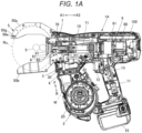
- FIG. 1A is an internal configuration view showing an example of an overall configuration of a reinforcing bar binding machine of the present embodiment, as seen from a side
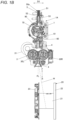
- FIG. 1B is an internal configuration view showing the example of the overall configuration of the reinforcing bar binding machine of the present embodiment, as seen from the front
- FIG. 1C is a side view showing the example of the overall configuration of the reinforcing bar binding machine of the present embodiment.
- a reinforcing bar binding machine 1A has such a shape that an operator grips with a hand, and includes a main body part 10 and a handle part 11.
- the reinforcing bar binding machine 1A feeds wires W in a forward direction indicated by an arrow F, winds the wires around reinforcing bars S, which are a to-be-bound object, feeds the wires W wound around the reinforcing bars S in a reverse direction indicated by an arrow R, winds the wires on the reinforcing bars S, and twists the wires W, thereby binding the reinforcing bars S with the wires W.
- the reinforcing bar binding machine 1A binds the reinforcing bars S with a plurality of wires W, in this example, two wires W.
- the reinforcing bar binding machine 1A includes a magazine 2 in which the wires W are accommodated, a wire feeding portion 3 that aligns two wires W in a radial direction of the wires W and feeds the wires W at a time, and a wire guide portion 4 that guides the two wires W, which are fed by the wire feeding portion 3.
- the reinforcing bar binding machine 1A includes a curl forming portion 5 that forms an annular feeding path for winding the two wires W, which are fed by the wire feeding portion 3, around the reinforcing bars S once, and a cutting portion 6 that cuts the two wires W wound on the reinforcing bars S.
- the reinforcing bar binding machine 1A includes a binding portion 7 that twists the two wires W wound on the reinforcing bars S, and a drive portion 8 that drives the binding portion 7.
- the annular feeding path along which the two wires W, which are fed by the wire feeding portion 3, are wound once around the reinforcing bars S is a path along which wires are fed when winding two wires around a to-be-bound object at a time in a single turn.
- the magazine 2 is an example of an accommodation portion, and a reel 20 on which the long wires W are wound to be reeled out is rotatably and detachably accommodated therein.
- a wire made of a plastically deformable metal wire, a wire having a metal wire covered with a resin, or a twisted wire is used.
- the reel 20 includes a tubular hub part 21 on which the wires W are wound and a pair of flange parts 22 and 23 integrally provided on both axial end sides of the hub part 21.
- the flange parts 22 and 23 have a substantially circular plate shape with a larger diameter than that of the hub part 21 and are provided concentrically with the hub part 21.
- the reel 20 is configured such that two wires W are wound on the hub part 21 and two wires W are pulled out from the reel 20 simultaneously.
- the reel 20 is attached in a state of being offset in one direction along an axial direction of the hub part 21 with respect to a feeding path FL of the wires W, which is defined by the wire feeding portion 3, the wire guide portion 4, and the like.
- the wire feeding portion 3 includes a pair of feeding gears 30 (30L, 30R) that sandwiches and feeds the two wires W aligned in parallel.
- a rotating operation of a feeding motor 31 is transmitted to one feeding gear 30L.
- engagement of gear portions provided on outer peripheries of the feeding gear 30L and the feeding gear 30R transmits a rotating operation of one feeding gear 30L to the other feeding gear 30R.
- one feeding gear 30L becomes a driving side
- the other feeding gear 30R becomes a driven side.
- the wire feeding portion 3 aligns two wires W in parallel along a direction in which the pair of feeding gears 30L and 30R is aligned. In the wire feeding portion 3, one wire W comes into contact with a groove portion of one feeding gear 30L, the other wire W comes into contact with a groove portion of the other feeding gear 30R, and one wire W and the other wire W come into contact with each other.
- the wire feeding portion 3 feeds two wires W, sandwiched between the pair of feeding gears 30 (30L, 30R), along an extension direction of the wires W by a frictional force generated between one feeding gear 30L and one wire W, a frictional force generated between the other feeding gear 30R and the other wire W, and a frictional force generated between the two wires W as the pair of feeding gears 30 (30L, 30R) rotates.
- a rotation direction of the feeding motor 31 is switched between forward and reverse directions to switch a rotation direction of the feeding gears 30, thereby switching a feeding direction of the wires W between the forward and reverse directions.
- the wire guide portion 4 is arranged on upstream and downstream sides of the feeding gears 30 with respect to the feeding direction of the wires W that are fed in the forward direction.
- the wire guide portion 4 aligns the two entering wires W in parallel along the direction in which the pair of feeding gears 30 is aligned and guides the same between the pair of feeding gears 30.
- the wire guide portion 4 is configured such that an opening area of an opening on the upstream side with respect to the feeding direction of the wires W, which are fed in the forward direction, is larger than that of an opening on the downstream side, and a part or all of an inner surface of the opening is tapered. This can facilitate an operation of inserting the wires W pulled out from the reel 20 accommodated in the magazine 2 into the wire guide portion 4.
- the curl forming portion 5 includes a curl guide 50a that curls two wires W, which are fed by the wire feeding portion 3, and regulates movement of each wire W in a direction in which the two wires W are aligned in parallel, and an induction guide 50b that guides the two wires W curled by the curl guide 50a to the binding portion 7.
- the curl forming portion 5 forms an annular feeding path Ru, indicated by a two-dot chain line in FIG. 1A , passing through the induction guide 50b from the curl guide 50a and reaching the binding portion 7 by curling the two wires W that are fed by the wire feeding portion 3 and pass through the curl guide 50a.
- the curl guide 50a suppresses one wire W of the two wires W from moving in a direction toward the other wire.
- the curl guide 50a suppresses the other wire W from moving in a direction toward one wire by one wire W of the two wires W. Thereby, the curl guide 50a suppresses the order of alignment of the two wires W, which are fed by the wire feeding portion 3 so as to be aligned along the axial direction of the annular feeding path Ru, from being switched.
- the cutting portion 6 includes a fixed blade part 60, a movable blade part 61 that cuts the wires W in cooperation with the fixed blade part 60, and a transmission mechanism 62 that transmits an operation of the binding portion 7 to the movable blade part 61.
- the binding portion 7 includes a wire locking body 70 to which the wires W are locked, and a sleeve 71 for actuating the wire locking body 70.
- the drive portion 8 includes a twist motor 80 and a decelerator 81 that performs deceleration and torque amplification.
- the reinforcing bar binding machine 1A includes a feeding regulation part 90, against which tips of the wires W are butted, at a terminal end of the feeding path of the wires W, which pass through the annular feeding path Ru and are locked by the wire locking body 70. Additionally, in the reinforcing bar binding machine 1A, the curl guide 50a and the induction guide 50b of the curl forming portion 5 are provided at an end portion on a front side of the main body part 10. Additionally, in the reinforcing bar binding machine 1A, a butting portion 91, against which the reinforcing bars S are butted, is provided between the curl guide 50a and the induction guide 50b at the end portion on the front side of the main body part 10.
- the handle part 11 extends downward from the main body part 10.
- a battery 15 is detachably mounted to a lower part of the handle part 11.
- the magazine 2 is provided in front of the handle part 11.
- a trigger 12 is provided on a front side of the handle part 11, and a switch 13 is provided inside the handle part 11.
- a control portion 100 controls the feeding motor 31 and the twist motor 80, in response to a state of the switch 13 that is pressed by an operation on the trigger 12.
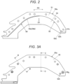
- FIG. 2 is a side view showing an example of the curl guide, with some components removed
- FIG. 3A is a side view showing the example of the curl guide
- FIG. 3B is a cross-sectional view taken along line B-B of FIG. 3A
- FIG. 3C is a cross-sectional view taken along line C-C of FIG. 3A
- FIG. 3D is a top view showing the example of the curl guide.
- FIG. 2 shows a state in which a second wire guide 52 described below is removed. Below, an example of the curl guide 50a will be described with reference to each drawing.
- the curl guide 50a includes a first wire guide 51 that regulates positions of the wires W directed toward a radially outer periphery side with respect to a radial direction of the annular feeding path Ru indicated by arrow D1 in FIG. 2 , along a circumferential direction of the annular feeding path Ru indicated by arrow D2.
- the curl guide 50a includes a second wire guide 52 that regulates positions of the wires W directed toward one axial side with respect to an axial direction of the annular feeding path Ru indicated by arrow D3 in FIGS. 3B and 3C , along the circumferential direction of the annular feeding path Ru indicated by arrow D2.
- the curl guide 50a includes a third wire guide 53 that regulates positions of the wires W directed toward the other axial side with respect to the axial direction of the annular feeding path Ru indicated by arrow D3, along the circumferential direction of the annular feeding path Ru indicated by arrow D2.
- the first wire guide 51 is sandwiched between the second wire guide 52 and the third wire guide 53.
- the second wire guide 52 protrudes inwardly from the first wire guide 51 along the radial direction of the annular feeding path Ru.
- the third wire guide 53 protrudes inwardly from the first wire guide 51 along the radial direction of the annular feeding path Ru.
- the second wire guide 52 and the third wire guide 53 face each other with a spacing corresponding to a thickness of the first wire guide 51.
- a spacing Ra1 between the second wire guide 52 and the third wire guide 53 is two times or greater a diameter R of the wire W.
- the spacing Ra1 between the second wire guide 52 and the third wire guide 53 may be set to about 1.5 times or greater the diameter R of the wire W. Additionally, in order to enable the two wires W to be aligned along the axial direction of the annular feeding path Ru while being in contact with each other, the spacing Ra1 between the second wire guide 52 and the third wire guide 53 is preferably set to about 1.9 times or greater the diameter R of the wire W.
- the first wire guide 51, the second wire guide 52, and the third wire guide 53 are not bent in the axial direction of the annular feeding path Ru indicated by arrow D3, and the entirety of the first wire guide 51, the second wire guide 52, and the third wire guide 53 extends in a straight line shape toward a discharge portion 50e from which the wires W, which are fed in the forward direction by the wire feed portion 3, are fed out.
- the curl guide 50a includes a guide member 50g at the discharge portion 50e.
- the guide member 50g has, for example, a cylindrical shape.
- the second wire guide 52 has a hole portion 52h into which the guide member 50g is press-fitted.
- the third wire guide 53 has a hole portion 53h into which the guide member 50g is press-fitted.
- the first wire guide 51 has a recessed portion 51h to which the guide member 50g is fitted.
- the positions of the hole portion 52h, the hole portion 53h, and the recessed portion 51h are aligned.
- the guide member 50g passes through the hole portion 52h and the hole portion 53h and is press-fitted into the curl guide 50a, so that a circumferential surface of the guide member 50g is exposed to a guide surface of the first wire guide 51.
- the curl guide 50a includes a suppression part 54 that suppresses one of the plurality of wires W, in the present example, one wire W1 of the two wires W, from moving in a direction toward the other wire W2.
- the suppression part 54 in a width direction of the first wire guide 51 along the axial direction of the annular feeding path Ru indicated by arrow D3, includes a guide portion 54a with varying heights along the radial direction of the annular feeding path Ru indicated by arrow D1.
- the guide portion 54a is provided on the first wire guide 51.
- the guide portion 54a in the width direction of the first wire guide 51 along the axial direction of the annular feeding path Ru indicated by arrow D3, includes an inclined surface 54b that is inclined in a direction toward an outer side along the radial direction of the annular feeding path Ru indicated by arrow D1, toward the second wire guide 52 on an opposite side to a side on which the reel 20 is offset.
- the guide portion 54a in the circumferential direction of the annular feeding path Ru indicated by arrow D2, is configured as a concave curved surface or the like along the annular feeding path Ru.
- the curl guide 50a includes a parallel guide part 55 that aligns two wires W in parallel and feeds the wires along the axial direction of the annular feeding path Ru indicated by arrow D3.
- the parallel guide part 55 is provided on the first wire guide 51 on a downstream side of the suppression part 54 with respect to the feeding direction of the wires W, which are fed in the forward direction indicated by arrow F.
- the parallel guide part 55 in the width direction of the first wire guide 51 along the axial direction of the annular feeding path Ru indicated by arrow D3, is configured as a surface along the axial direction of the annular feeding path Ru.
- the surface along the axial direction of the annular feeding path Ru is a surface along a direction in which the guide member 50g extends.
- the parallel guide part 55 in the circumferential direction of the annular feeding path Ru indicated by arrow D2, is configured as a concave curved surface or the like along the annular feeding path Ru.
- a part of the parallel guide part may be configured by the circumferential surface of the cylindrical guide member 50g.
- the height of the suppression part 54 along the radial direction of the annular feeding path Ru indicated by arrow D1 gradually changes toward the parallel guide part 55. That is, the guide portion 54a connects to the parallel guide part 55, with an inclination that gradually decreases from the upstream side toward the downstream side with respect to the feeding direction of the wires W, which are fed in the forward direction indicated by arrow F.
- the suppression part 54 is preferably provided within a range of at least 1/4 of the annular feeding path Ru in the circumferential direction of the annular feeding path Ru indicated by arrow D2.
- the suppression part 54 is preferably provided upstream of the curl guide 50a with respect to the feeding direction of the wires W, which are fed in the forward direction indicated by arrow F.
- the range in which the guide portion 54a is provided has a length of approximately half of the curl guide 50a in the circumferential direction of the annular feeding path Ru indicated by arrow D2.
- the feeding motor 31 is driven in the forward rotation direction, and two wires W are fed in the forward direction indicated by arrow F by the wire feeding portion 3.
- the two wires W which are fed in the forward direction by the wire feeding portion 3, are aligned in parallel along the axial direction of the annular feeding path Ru by the wire guide portion 4 on the upstream side of the curl guide 50a.
- the two wires W which are fed in the forward direction, are fed to the curl guide 50a of the curl forming portion 5.
- the two wires W by passing through the curl guide 50a, come into contact with the first wire guide 51 and are curled to be wound around the reinforcing bars S along the annular feeding path Ru.
- the two wires W wound on the reel 20 are integrally connected at tips by being twisted, crimped, or the like before use, so as to facilitate an operation upon insertion of the wires between the pair of feeding gears 30.
- a direction in which they are aligned in parallel is defined by the pair of feeding gears 30 of the wire feeding portion 3 and the wire guide portion 4.
- the other wire W2 When the other wire W2 attempts to move in the direction toward the second wire guide 52 indicated by arrow D32, the other wire W2 comes into contact with the one wire W1.
- the one wire W1 comes into contact with the second wire guide 52 and is regulated from moving in the axial direction of the annular feeding path Ru indicated by arrow D3. Thereby, the other wire W2 is suppressed from further moving in the direction toward the second wire guide 52 indicated by arrow D32, via the one wire W1.
- the two wires W by passing through the curl guide 50a, are fed without the positions of the two wires W being switched in the annular feeding path Ru by the suppression part 54.
- the two wires W are aligned in parallel in the axial direction of the annular feeding path Ru by the parallel guide part 55 and pass through the curl guide 50a.
- one wire W1 by coming into contact with the inclined surface 54b of the guide portion 54a, is suppressed from moving in the direction toward the third wire guide 53 indicated by arrow D31 and from moving in the direction toward the other wire W2.
- one wire W1 by coming into contact with the inclined surface 54b of the guide portion 54a, is subjected to a force that causes it to move in the direction toward the second wire guide 52 indicated by arrow D32, and thus can move in the direction of arrow D32 up to a position where it comes into contact with the second wire guide 52.
- the suppression part 54 including the guide portion 54a can be regarded as functioning as a guiding part that guides one wire W1 toward the second wire guide 52.
- the orientation of the parallel guide part 55 along the axial direction of the annular feeding path Ru indicated by arrow D3 is substantially perpendicular to the plate-shaped member constituting the first wire guide 51, the plate-shaped member constituting the second wire guide 52, and the plate-shaped member constituting the third wire guide 53.
- the curl guide 50a is provided with the parallel guide part 55 at the discharge portion 50e in the circumferential direction of the annular feeding path Ru indicated by arrow D2, as well as the guide member 50g.
- the guide portion 54a in the width direction of the first wire guide 51 along the axial direction of the annular feeding path Ru indicated by arrow D3, may be configured as an inclined surface that is inclined in a direction toward an outer side along the radial direction of the annular feeding path Ru indicated by arrow D1, toward the third wire guide 53.
- the suppression part 54 including the guide portion 54a may function as a guiding part that guides one wire of the plurality of wires toward the third wire guide 53.
- the guide portion 54a in the width direction of the first wire guide 51 along the axial direction of the annular feeding path Ru indicated by arrow D3, may be configured with an inclined surface that is inclined in a direction toward the outer side along the radial direction of the annular feeding path Ru indicated by arrow D 1 from a central vicinity toward the second wire guide 52 and an inclined surface that is inclined in a direction toward the outer side along the radial direction of the annular feeding path Ru indicated by arrow D1 from the central vicinity toward the third wire guide 53.
- the suppression part 54 including the guide portion 54a may function as a guiding part that guides one of the plurality of wires toward the second wire guide 52 or the third wire guide 53.
- the curl guide 50c includes a suppression part 56 that suppresses one of the plurality of wires W, in the present example, one wire W1 of the two wires W, from moving in a direction toward the other wire W2.
- the suppression part 56 in a width direction of the first wire guide 51c along the axial direction of the annular feeding path Ru indicated by arrow D3, includes a guide portion 56a with varying heights along the radial direction of the annular feeding path Ru indicated by arrow D1.
- the guide portion 56a is provided on the first wire guide 51c.
- the guide portion 56a in the width direction of the first wire guide 51 along the axial direction of the annular feeding path Ru indicated by arrow D3, is configured with an inclined surface 56b that is inclined in a direction toward the outer side along the radial direction of the annular feeding path Ru indicated by arrow D1, toward the second wire guide 52, over a range of about half of a side closer to at least the second wire guide 52, in the present example, closer to the second wire guide 52.
- the guide portion 56a may be configured with an inclined surface that is inclined in the direction toward the outer side along the radial direction of the annular feeding path Ru indicated by arrow D1, toward the third wire guide 53, over a range of about half of a side closer to the third wire guide 53.
- the guide portion 56a, in the circumferential direction of the annular feeding path Ru indicated by arrow D2, is formed with the inclined surface 56b over an entire range.
- the guide portion 56a, in the circumferential direction of the annular feeding path Ru indicated by arrow D2 is configured as a concave curved surface or the like along the annular feeding path Ru.
- FIG. 6 is a side view showing a variation of another example of the curl guide, with some components removed.
- FIG. 6 shows a state in which the second wire guide 52 shown in FIG. 5B and the like is removed.
- a curl guide 50c2 includes a first wire guide 51c2 that regulates positions of the wires W, which are directed toward the radially outer periphery side with respect to the radial direction of the annular feeding path Ru indicated by arrow D 1 in FIG. 6 , along the circumferential direction of the annular feeding path Ru indicated by arrow D2.
- the first wire guide 51c2 includes the suppression part 56 described above, and the suppression part 56 includes a guide portion 56a.
- the parallel guide part 57 in the width direction of the first wire guide 51c along the axial direction of the annular feeding path Ru indicated by arrow D3, is configured as a surface along the axial direction of the annular feeding path Ru.
- the guide portion 56a connects to the parallel guide part 57, with an inclination that gradually decreases toward the downstream side with respect to the feeding direction of the wires W, which are fed in the forward direction indicated by arrow F.
- one wire W1 passing through a side closer to the second wire guide 52 comes into contact with the guide portion 56a, as shown in FIG. 5B .
- the one wire W1 comes into contact with the guide portion 56a during the process of feeding the wires W by the wire feeding portion 3
- the one wire W1 is suppressed from moving in the direction toward the third wire guide 53 indicated by arrow D31 due to the inclined surface 56b of the guide portion 56a.
- the one wire W1 is suppressed from moving in the direction toward the other wire W2, and the positions of the two wires W are suppressed from being switched between the second wire guide 52 and the third wire guide 53.
- the one wire W1 is subjected to a force that causes the wire to move in a direction toward the second wire guide 52 indicated by arrow D32 due to the inclined surface 56b of the guide portion 56a.
- the one wire W1 moves in the direction toward the second wire guide 52 indicated by arrow D32, it comes into contact with the second wire guide 52 and is regulated from moving in the axial direction of the annular feeding path Ru indicated by arrow D3.
- the other wire W2 When the other wire W2 attempts to move in the direction toward the second wire guide 52 indicated by arrow D32, the other wire W2 comes into contact with the one wire W1.
- the one wire W1 comes into contact with the second wire guide 52 and is regulated from moving in the axial direction of the annular feeding path Ru indicated by arrow D3. Thereby, the other wire W2 is suppressed from further moving in the direction toward the second wire guide 52 indicated by arrow D32, via the one wire W1.
- the other wire W2 is suppressed from moving in the direction toward the one wire W1, and the positions of the two wires W are suppressed from being switched between the second wire guide 52 and the third wire guide 53.
- the two wires W by passing through the curl guide 50c, 50c2, are guided in a state in which their positions are suppressed from being switched in the axial direction of the annular feeding path Ru by the suppression part 56.
- one wire W1 by coming into contact with the inclined surface 56b of the guide portion 56a, is suppressed from moving in the direction toward the third wire guide 53 indicated by arrow D31 and from moving in the direction toward the other wire W2.
- one wire W1 by coming into contact with the inclined surface 56b of the guide portion 56a, is subjected to a force that causes it to move in the direction toward the second wire guide 52 indicated by arrow D32, and thus can move in the direction of arrow D32 up to a position where it comes into contact with the second wire guide 52.
- the suppression part 56 including the guide portion 56a can be regarded as functioning as a guiding portion that guides one wire W1 toward the second wire guide 52.
- the other wire W2 by coming into contact with the one wire W1, is suppressed from moving in the direction toward the second wire guide 52 indicated by arrow D32. Therefore, the one wire W1 and the other wire W2 are suppressed from moving in the axial direction of the annular feeding path Ru indicated by arrow D3. Thereby, within the curl guide 50c, 50c2, a movable range of the wires W in the left-right direction is reduced.
- the suppression part 56 including the guide portion 56a may function as a guiding part that guides one wire of the plurality of wires toward the third wire guide 53.
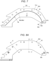
- FIG. 7 is a side view showing still another example of the curl guide, with some components removed
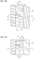
- FIG. 8A is a side view showing still another example of the curl guide
- FIG. 8B is a cross-sectional view taken along line E-E of FIG. 8A
- FIG. 8C is a cross-sectional view taken along line F-F of FIG. 8A.
- FIG. 7 shows a state in which the second wire guide 52 is removed.
- the curl guide 50d includes a first wire guide 51d that regulates positions of the wires W, which are directed toward the radially outer periphery side with respect to the radial direction of the annular feeding path Ru indicated by arrow D1 in FIG. 7 , along the circumferential direction of the annular feeding path Ru indicated by arrow D2.
- the first wire guide 51d is sandwiched between the second wire guide 52 and the third wire guide 53 with respect to the axial direction of the annular feeding path Ru indicated by arrow D3 in FIG. 8B .
- the second wire guide 52 and the third wire guide 53 face each other with a spacing corresponding to a thickness of the first wire guide 51d.
- a spacing Ra1 between the second wire guide 52 and the third wire guide 53 is two times or greater than the diameter R of the wire W.
- the curl guide 50d includes a suppression part 58 that suppresses one of the plurality of wires W, in the present example, one wire W1 of the two wires W, from moving in the axial direction of the annular feeding path.
- the suppression part 58 in a width direction of the first wire guide 51d along the axial direction of the annular feeding path Ru indicated by arrow D3, includes a guide portion 58a with varying heights along the radial direction of the annular feeding path Ru indicated by arrow D1.
- the guide portion 58a is provided on the first wire guide 51d.
- the guide portion 58a includes a vertical wall 58b facing the second wire guide 52.
- the guide portion 58a is provided with a step on a side closer to the second wire guide 52 in the width direction of the first wire guide 51 along the axial direction of the annular feeding path Ru indicated by arrow D3, the step having a concave shape in the direction toward the outer side along the radial direction of the annular feeding path Ru indicated by arrow D 1 and accommodating one wire W1.
- the guide portion 58a is a step with a width along the axial direction of the annular feeding path Ru indicated by arrow D3, which is slightly larger than the diameter R of the wire W, and a depth along the radial direction of the annular feeding path Ru indicated by arrow D1, which is about half the diameter R of the wire W.
- the vertical wall 58b faces the second wire guide 52 with a spacing equal to or greater than the diameter of the wire W.
- the guide portion 58a in the circumferential direction of the annular feeding path Ru indicated by arrow D2, is configured as a concave curved surface or the like along the annular feeding path Ru.
- the vertical wall 58b is formed up to the vicinity of the discharge portion 50e of the curl guide 50d.
- the curl guide 50d has a parallel guide part 59 formed at the discharge portion 50e.
- the parallel guide part 59 in the width direction of the first wire guide 51d along the axial direction of the annular feeding path Ru indicated by arrow D3, is configured as a surface along the axial direction of the annular feeding path Ru.
- the guide portion 58a connects to the parallel guide part 59, with a height of the vertical wall 58b gradually decreasing toward the downstream side with respect to the feeding direction of the wires W, which are fed in the forward direction indicated by arrow F.
- one wire W1 passing through a side closer to the second wire guide 52 enters the guide portion 58a, as shown in FIG. 8B .
- the one wire W1 enters the guide portion 58a during the process of feeding the wires W, the one wire W1 is suppressed from moving in the direction toward the third wire guide 53 indicated by arrow D31 due to the vertical wall 58b of the guide portion 58a. Accordingly, the one wire W1 is suppressed from moving in the direction toward the other wire W2, and the positions of the two wires W are suppressed from being switched between the second wire guide 52 and the third wire guide 53.
- the one wire W1 when the one wire W1 attempts to move in the direction toward the second wire guide 52 indicated by arrow D32, the one wire W1 is regulated from moving in the axial direction of the annular feeding path Ru indicated by arrow D3 if the one wire W1 comes into contact with the second wire guide 52.
- the other wire W2 When the other wire W2 attempts to move in the direction toward the second wire guide 52 indicated by arrow D32, the other wire W2 comes into contact with the one wire W1.
- the one wire W1 comes into contact with the second wire guide 52 and is regulated from moving in the axial direction of the annular feeding path Ru indicated by arrow D3. Thereby, the other wire W2 is suppressed from further moving in the direction toward the second wire guide 52 indicated by arrow D32, via the one wire W1.
- the other wire W2 is suppressed from moving in the direction toward the one wire W1, and the positions of the two wires W are suppressed from being switched between the second wire guide 52 and the third wire guide 53.
- the two wires W by passing through the curl guide 50d, are guided in a state in which their positions are suppressed from being switched in the axial direction of the annular feeding path Ru by the suppression part 58.
- the one wire W1 by coming into contact with the vertical wall 58b of the guide portion 58a, is suppressed from moving in the direction toward the third wire guide 53 indicated by arrow D31 and from moving in the direction toward the other wire W2. Additionally, the one wire W can move in the direction toward the second wire guide 52 indicated by arrow D32 until it comes into contact with the second wire guide 52. The other wire W2, by coming into contact with the one wire W1, is suppressed from moving in the direction toward the second wire guide 52 indicated by arrow D32. Therefore, the one wire W1 and the other wire W2 are suppressed from moving in the axial direction of the annular feeding path Ru indicated by arrow D3.
- an aspect of the present disclosure is a binding machine including: a wire feeding portion configured to feed a plurality of wires; a curl forming portion configured to form an annular feeding path for winding the plurality of wires fed by the wire feeding portion around a to-be-bound object; and a binding portion configured to twist the plurality of wires wound on the to-be-bound object.
- the curl forming portion includes a curl guide configured to curl the plurality of wires fed by the wire feeding portion, and an induction guide configured to guide the plurality of wires curled by the curl guide to the binding portion.
- the curl guide includes a first wire guide configured to regulate positions of the wires directed toward a radially outer periphery side with respect to a radial direction of the annular feeding path, a second wire guide configured to regulate positions of the wires directed toward one axial side with respect to an axial direction of the annular feeding path, and a third wire guide configured to regulate positions of the wires directed toward the other axial side.
- the curl guide includes a suppression part configured to allow the plurality of wires to be aligned in contact with each other between the second wire guide and the third wire guide along the axial direction of the annular feeding path, and to suppress one wire of the plurality of wires from moving in a direction toward another wire.
- one wire of a plurality of wires which are fed to the curl forming portion by the wire feeding portion and aligned between the second wire guide and the third wire guide along the axial direction of the annular feeding path, is suppressed by the suppression part from moving in the direction toward another wire.
- the present disclosure by suppressing one wire of the plurality of wires aligned between the second wire guide and the third wire guide from moving in the direction toward another wire, it is possible to suppress the order of alignment of the plurality of wires aligned along the axial direction of the annular feeding path from being switched. This can stabilize the posture of the wires in the air after being fed out from the curl guide. Therefore, even when the diameter of the annular feeding path increases, it is possible to feed the plurality of wires so that the wires enter the induction guide from the curl guide, without enlarging the induction guide. Accordingly, it is possible to suppress increases in size and weight of the binding machine and a deterioration of operability.
Landscapes
- Engineering & Computer Science (AREA)
- Mechanical Engineering (AREA)
- Architecture (AREA)
- Civil Engineering (AREA)
- Structural Engineering (AREA)
- Basic Packing Technique (AREA)
- Reinforcement Elements For Buildings (AREA)
Abstract
A binding machine includes a curl forming portion. The curl forming portion includes a curl guide configured to curl a plurality of wires. The curl guide includes a first wire guide configured to regulate positions of the wires directed toward a radially outer periphery side with respect to a radial direction of a annular feeding path, a second wire guide configured to regulate positions of the wires directed toward one axial side with respect to an axial direction of the annular feeding path, and a third wire guide configured to regulate positions of the wires directed toward the other axial side. The curl guide includes a suppression part configured to suppress one wire of the plurality of wires from moving in a direction toward another wire.
Description
- The present disclosure relates to a binding machine for binding a to-be-bound object, such as a reinforcing bar, with a wire.
- For concrete buildings, reinforcing bars are used so as to improve strength. The reinforcing bars are bound with wires so that the reinforcing bars do not deviate from predetermined positions during concrete placement.
- In the related art, suggested is a binding machine referred to as a reinforcing bar binding machine configured to wind a wire on two or more reinforcing bars and to twist the wire wound on the reinforcing bars, thereby binding the two or more reinforcing bars with the wire.
- When binding reinforcing bars with a wire, the reinforcing bars will become misaligned if the binding is loose. Therefore, it is required to bind and maintain the reinforcing bars tightly. By using a wire with a large diameter, it is possible to ensure the binding strength of the reinforcing bars. However, if a wire with a large diameter is used, the rigidity of the wire increases, so a greater force is required to bind the reinforcing bars.
- Accordingly, a binding machine is proposed which includes a feeding means capable of feeding two or more wires and winding the wires around a to-be-bound object and a binding means for binding the to-be-bound object by gripping and twisting the two or more wires wound around the to-be-bound object by the feeding means, and the feeding means aligns the two or more wires in parallel in an axial direction of a wire feeding path having an annular shape and feeds the wires (for example, see Patent Literature 1).
- Patent Literature 1:
Japanese Patent No. 6791141B - In the binding machine that aligns two or more wires in parallel and feeds the wires, when one of the plurality of wires moves in a direction toward another wire in a curl guide, which curls the wires, it affects a posture of the wires in the air after being fed out from the curl guide. When the posture of the wires in the air varies, a landing position on an induction guide that guides the wires to the binding means also varies.
- When a diameter of the reinforcing bars to be bound with the wire increases, it is necessary to increase a diameter of the feeding path of the wires that are wound in an annular shape around the reinforcing bars. However, the variation of the landing position on the induction guide increases as the diameter of the annular feeding path increases. For this reason, there is a possibility that the wires will not enter the induction guide. In contrast, if the induction guide is enlarged to ensure that the wires enter the induction guide, the binding machine may increase in size or weight, potentially leading to a deterioration of operability.
- The present disclosure has been made in view of the above problems, and an object thereof is to provide a binding machine that can suppress one of a plurality of wires from moving in a direction toward another wire in a curl guide.
- An aspect of the present disclosure is a binding machine including: a wire feeding portion configured to feed a plurality of wires; a curl forming portion configured to form an annular feeding path for winding the plurality of wires fed by the wire feeding portion around a to-be-bound object; and a binding portion configured to twist the plurality of wires wound on the to-be-bound object. The curl forming portion includes a curl guide configured to curl the plurality of wires fed by the wire feeding portion, and an induction guide configured to guide the plurality of wires curled by the curl guide to the binding portion. The curl guide includes a first wire guide configured to regulate positions of the wires directed toward a radially outer periphery side with respect to a radial direction of the annular feeding path, a second wire guide configured to regulate positions of the wires directed toward one axial side with respect to an axial direction of the annular feeding path, and a third wire guide configured to regulate positions of the wires directed toward the other axial side. The curl guide includes a suppression part configured to allow the plurality of wires to be aligned in contact with each other between the second wire guide and the third wire guide along the axial direction of the annular feeding path, and to suppress one wire of the plurality of wires from moving in a direction toward another wire.
-
-
FIG. 1A is an internal configuration view showing an example of an overall configuration of a reinforcing bar binding machine of the present embodiment, as seen from a side. -
FIG. 1B is an internal configuration view showing the example of the overall configuration of the reinforcing bar binding machine of the present embodiment, as seen from the front. -
FIG. 1C is a side view showing the example of the overall configuration of the reinforcing bar binding machine of the present embodiment. -
FIG. 2 is a side view showing an example of a curl guide, with some components removed. -
FIG. 3A is a side view showing the example of the curl guide. -
FIG. 3B is a cross-sectional view taken along line B-B ofFIG. 3A . -
FIG. 3C is a cross-sectional view taken along line C-C ofFIG. 3A . -
FIG. 3D is a top view showing the example of the curl guide. -
FIG. 4 is a side view showing another example of the curl guide, with some components removed. -
FIG. 5A is a side view showing another example of the curl guide. -
FIG. 5B is a cross-sectional view taken along line D-D ofFIG. 5A . -
FIG. 6 is a side view showing a variation of another example of the curl guide, with some components removed. -
FIG. 7 is a side view showing still another example of the curl guide, with some components removed. -
FIG. 8A is a side view showing still another example of the curl guide. -
FIG. 8B is a cross-sectional view taken along line E-E ofFIG. 8A . -
FIG. 8C is a cross-sectional view taken along line F-F ofFIG. 8A . - Hereinafter, an example of a reinforcing bar binding machine as an embodiment of the binding machine of the present disclosure will be described with reference to the drawings.
-
FIG. 1A is an internal configuration view showing an example of an overall configuration of a reinforcing bar binding machine of the present embodiment, as seen from a side,FIG. 1B is an internal configuration view showing the example of the overall configuration of the reinforcing bar binding machine of the present embodiment, as seen from the front, andFIG. 1C is a side view showing the example of the overall configuration of the reinforcing bar binding machine of the present embodiment. - A reinforcing
bar binding machine 1A has such a shape that an operator grips with a hand, and includes amain body part 10 and ahandle part 11. In addition, the reinforcingbar binding machine 1A feeds wires W in a forward direction indicated by an arrow F, winds the wires around reinforcing bars S, which are a to-be-bound object, feeds the wires W wound around the reinforcing bars S in a reverse direction indicated by an arrow R, winds the wires on the reinforcing bars S, and twists the wires W, thereby binding the reinforcing bars S with the wires W. The reinforcingbar binding machine 1A binds the reinforcing bars S with a plurality of wires W, in this example, two wires W. - In order to implement the above-described functions, the reinforcing
bar binding machine 1A includes amagazine 2 in which the wires W are accommodated, awire feeding portion 3 that aligns two wires W in a radial direction of the wires W and feeds the wires W at a time, and awire guide portion 4 that guides the two wires W, which are fed by thewire feeding portion 3. In addition, the reinforcingbar binding machine 1A includes acurl forming portion 5 that forms an annular feeding path for winding the two wires W, which are fed by thewire feeding portion 3, around the reinforcing bars S once, and a cuttingportion 6 that cuts the two wires W wound on the reinforcing bars S. In addition, the reinforcingbar binding machine 1A includes abinding portion 7 that twists the two wires W wound on the reinforcing bars S, and adrive portion 8 that drives the bindingportion 7. Note that the annular feeding path along which the two wires W, which are fed by thewire feeding portion 3, are wound once around the reinforcing bars S, is a path along which wires are fed when winding two wires around a to-be-bound object at a time in a single turn. - The
magazine 2 is an example of an accommodation portion, and areel 20 on which the long wires W are wound to be reeled out is rotatably and detachably accommodated therein. For the wire W, a wire made of a plastically deformable metal wire, a wire having a metal wire covered with a resin, or a twisted wire is used. - The
reel 20 includes atubular hub part 21 on which the wires W are wound and a pair offlange parts hub part 21. Theflange parts hub part 21 and are provided concentrically with thehub part 21. Thereel 20 is configured such that two wires W are wound on thehub part 21 and two wires W are pulled out from thereel 20 simultaneously. - As shown in
FIG. 1B , in the reinforcingbar binding machine 1A, thereel 20 is attached in a state of being offset in one direction along an axial direction of thehub part 21 with respect to a feeding path FL of the wires W, which is defined by thewire feeding portion 3, thewire guide portion 4, and the like. - The
wire feeding portion 3 includes a pair of feeding gears 30 (30L, 30R) that sandwiches and feeds the two wires W aligned in parallel. In thewire feeding portion 3, a rotating operation of a feedingmotor 31 is transmitted to onefeeding gear 30L. Additionally, engagement of gear portions provided on outer peripheries of thefeeding gear 30L and thefeeding gear 30R transmits a rotating operation of onefeeding gear 30L to theother feeding gear 30R. Thereby, onefeeding gear 30L becomes a driving side, and theother feeding gear 30R becomes a driven side. - The
wire feeding portion 3 aligns two wires W in parallel along a direction in which the pair of feeding gears 30L and 30R is aligned. In thewire feeding portion 3, one wire W comes into contact with a groove portion of onefeeding gear 30L, the other wire W comes into contact with a groove portion of theother feeding gear 30R, and one wire W and the other wire W come into contact with each other. Thereby, thewire feeding portion 3 feeds two wires W, sandwiched between the pair of feeding gears 30 (30L, 30R), along an extension direction of the wires W by a frictional force generated between onefeeding gear 30L and one wire W, a frictional force generated between theother feeding gear 30R and the other wire W, and a frictional force generated between the two wires W as the pair of feeding gears 30 (30L, 30R) rotates. - Additionally, in the
wire feeding portion 3, a rotation direction of the feedingmotor 31 is switched between forward and reverse directions to switch a rotation direction of the feeding gears 30, thereby switching a feeding direction of the wires W between the forward and reverse directions. - The
wire guide portion 4 is arranged on upstream and downstream sides of the feeding gears 30 with respect to the feeding direction of the wires W that are fed in the forward direction. Thewire guide portion 4 aligns the two entering wires W in parallel along the direction in which the pair of feeding gears 30 is aligned and guides the same between the pair of feeding gears 30. - The
wire guide portion 4 is configured such that an opening area of an opening on the upstream side with respect to the feeding direction of the wires W, which are fed in the forward direction, is larger than that of an opening on the downstream side, and a part or all of an inner surface of the opening is tapered. This can facilitate an operation of inserting the wires W pulled out from thereel 20 accommodated in themagazine 2 into thewire guide portion 4. - The
curl forming portion 5 includes acurl guide 50a that curls two wires W, which are fed by thewire feeding portion 3, and regulates movement of each wire W in a direction in which the two wires W are aligned in parallel, and aninduction guide 50b that guides the two wires W curled by thecurl guide 50a to thebinding portion 7. Thecurl forming portion 5 forms an annular feeding path Ru, indicated by a two-dot chain line inFIG. 1A , passing through theinduction guide 50b from thecurl guide 50a and reaching the bindingportion 7 by curling the two wires W that are fed by thewire feeding portion 3 and pass through thecurl guide 50a. Thecurl guide 50a suppresses one wire W of the two wires W from moving in a direction toward the other wire. Additionally, thecurl guide 50a suppresses the other wire W from moving in a direction toward one wire by one wire W of the two wires W. Thereby, thecurl guide 50a suppresses the order of alignment of the two wires W, which are fed by thewire feeding portion 3 so as to be aligned along the axial direction of the annular feeding path Ru, from being switched. - The cutting
portion 6 includes a fixedblade part 60, amovable blade part 61 that cuts the wires W in cooperation with the fixedblade part 60, and atransmission mechanism 62 that transmits an operation of thebinding portion 7 to themovable blade part 61. - The binding
portion 7 includes awire locking body 70 to which the wires W are locked, and asleeve 71 for actuating thewire locking body 70. Thedrive portion 8 includes atwist motor 80 and adecelerator 81 that performs deceleration and torque amplification. - The reinforcing
bar binding machine 1A includes afeeding regulation part 90, against which tips of the wires W are butted, at a terminal end of the feeding path of the wires W, which pass through the annular feeding path Ru and are locked by thewire locking body 70. Additionally, in the reinforcingbar binding machine 1A, thecurl guide 50a and theinduction guide 50b of thecurl forming portion 5 are provided at an end portion on a front side of themain body part 10. Additionally, in the reinforcingbar binding machine 1A, a buttingportion 91, against which the reinforcing bars S are butted, is provided between thecurl guide 50a and theinduction guide 50b at the end portion on the front side of themain body part 10. - In the reinforcing
bar binding machine 1A, thehandle part 11 extends downward from themain body part 10. In addition, abattery 15 is detachably mounted to a lower part of thehandle part 11. In addition, in the reinforcingbar binding machine 1A, themagazine 2 is provided in front of thehandle part 11. - In the reinforcing
bar binding machine 1A, atrigger 12 is provided on a front side of thehandle part 11, and aswitch 13 is provided inside thehandle part 11. In the reinforcingbar binding machine 1A, acontrol portion 100 controls the feedingmotor 31 and thetwist motor 80, in response to a state of theswitch 13 that is pressed by an operation on thetrigger 12. -
FIG. 2 is a side view showing an example of the curl guide, with some components removed,FIG. 3A is a side view showing the example of the curl guide,FIG. 3B is a cross-sectional view taken along line B-B ofFIG. 3A ,FIG. 3C is a cross-sectional view taken along line C-C ofFIG. 3A , andFIG. 3D is a top view showing the example of the curl guide.FIG. 2 shows a state in which asecond wire guide 52 described below is removed. Below, an example of thecurl guide 50a will be described with reference to each drawing. - The
curl guide 50a includes afirst wire guide 51 that regulates positions of the wires W directed toward a radially outer periphery side with respect to a radial direction of the annular feeding path Ru indicated by arrow D1 inFIG. 2 , along a circumferential direction of the annular feeding path Ru indicated by arrow D2. - Additionally, the
curl guide 50a includes asecond wire guide 52 that regulates positions of the wires W directed toward one axial side with respect to an axial direction of the annular feeding path Ru indicated by arrow D3 inFIGS. 3B and 3C , along the circumferential direction of the annular feeding path Ru indicated by arrow D2. - Additionally, the
curl guide 50a includes athird wire guide 53 that regulates positions of the wires W directed toward the other axial side with respect to the axial direction of the annular feeding path Ru indicated by arrow D3, along the circumferential direction of the annular feeding path Ru indicated by arrow D2. - In the
curl guide 50a, thefirst wire guide 51 is sandwiched between thesecond wire guide 52 and thethird wire guide 53. Thesecond wire guide 52 protrudes inwardly from thefirst wire guide 51 along the radial direction of the annular feeding path Ru. Thethird wire guide 53 protrudes inwardly from thefirst wire guide 51 along the radial direction of the annular feeding path Ru. Thereby, in thecurl guide 50a, thesecond wire guide 52 and thethird wire guide 53 face each other with a spacing corresponding to a thickness of thefirst wire guide 51. A spacing Ra1 between thesecond wire guide 52 and thethird wire guide 53 is two times or greater a diameter R of the wire W. - Note that the spacing Ra1 between the
second wire guide 52 and thethird wire guide 53 may be set to about 1.5 times or greater the diameter R of the wire W. Additionally, in order to enable the two wires W to be aligned along the axial direction of the annular feeding path Ru while being in contact with each other, the spacing Ra1 between thesecond wire guide 52 and thethird wire guide 53 is preferably set to about 1.9 times or greater the diameter R of the wire W. - In the
curl guide 50a, thefirst wire guide 51, thesecond wire guide 52, and thethird wire guide 53 are not bent in the axial direction of the annular feeding path Ru indicated by arrow D3, and the entirety of thefirst wire guide 51, thesecond wire guide 52, and thethird wire guide 53 extends in a straight line shape toward adischarge portion 50e from which the wires W, which are fed in the forward direction by thewire feed portion 3, are fed out. Thecurl guide 50a includes aguide member 50g at thedischarge portion 50e. Theguide member 50g has, for example, a cylindrical shape. Thesecond wire guide 52 has ahole portion 52h into which theguide member 50g is press-fitted. Thethird wire guide 53 has ahole portion 53h into which theguide member 50g is press-fitted. Additionally, thefirst wire guide 51 has a recessedportion 51h to which theguide member 50g is fitted. In thecurl guide 50a, when thefirst wire guide 51 is sandwiched between thesecond wire guide 52 and thethird wire guide 53, the positions of thehole portion 52h, thehole portion 53h, and the recessedportion 51h are aligned. Theguide member 50g passes through thehole portion 52h and thehole portion 53h and is press-fitted into thecurl guide 50a, so that a circumferential surface of theguide member 50g is exposed to a guide surface of thefirst wire guide 51. - The
curl guide 50a includes asuppression part 54 that suppresses one of the plurality of wires W, in the present example, one wire W1 of the two wires W, from moving in a direction toward the other wire W2. Thesuppression part 54, in a width direction of thefirst wire guide 51 along the axial direction of the annular feeding path Ru indicated by arrow D3, includes aguide portion 54a with varying heights along the radial direction of the annular feeding path Ru indicated by arrow D1. - The
guide portion 54a is provided on thefirst wire guide 51. Theguide portion 54a, in the width direction of thefirst wire guide 51 along the axial direction of the annular feeding path Ru indicated by arrow D3, includes aninclined surface 54b that is inclined in a direction toward an outer side along the radial direction of the annular feeding path Ru indicated by arrow D1, toward thesecond wire guide 52 on an opposite side to a side on which thereel 20 is offset. Additionally, theguide portion 54a, in the circumferential direction of the annular feeding path Ru indicated by arrow D2, is configured as a concave curved surface or the like along the annular feeding path Ru. - The
curl guide 50a includes aparallel guide part 55 that aligns two wires W in parallel and feeds the wires along the axial direction of the annular feeding path Ru indicated by arrow D3. Theparallel guide part 55 is provided on thefirst wire guide 51 on a downstream side of thesuppression part 54 with respect to the feeding direction of the wires W, which are fed in the forward direction indicated by arrow F. Theparallel guide part 55, in the width direction of thefirst wire guide 51 along the axial direction of the annular feeding path Ru indicated by arrow D3, is configured as a surface along the axial direction of the annular feeding path Ru. The surface along the axial direction of the annular feeding path Ru is a surface along a direction in which theguide member 50g extends. Additionally, theparallel guide part 55, in the circumferential direction of the annular feeding path Ru indicated by arrow D2, is configured as a concave curved surface or the like along the annular feeding path Ru. In addition, a part of the parallel guide part may be configured by the circumferential surface of thecylindrical guide member 50g. - The height of the
suppression part 54 along the radial direction of the annular feeding path Ru indicated by arrow D1 gradually changes toward theparallel guide part 55. That is, theguide portion 54a connects to theparallel guide part 55, with an inclination that gradually decreases from the upstream side toward the downstream side with respect to the feeding direction of the wires W, which are fed in the forward direction indicated by arrow F. - The
suppression part 54 is preferably provided within a range of at least 1/4 of the annular feeding path Ru in the circumferential direction of the annular feeding path Ru indicated by arrow D2. In addition, thesuppression part 54 is preferably provided upstream of thecurl guide 50a with respect to the feeding direction of the wires W, which are fed in the forward direction indicated by arrow F. The range in which theguide portion 54a is provided has a length of approximately half of thecurl guide 50a in the circumferential direction of the annular feeding path Ru indicated by arrow D2. - In the reinforcing
bar binding machine 1A, when thetrigger 12 is operated, the feedingmotor 31 is driven in the forward rotation direction, and two wires W are fed in the forward direction indicated by arrow F by thewire feeding portion 3. - The two wires W, which are fed in the forward direction by the
wire feeding portion 3, are aligned in parallel along the axial direction of the annular feeding path Ru by thewire guide portion 4 on the upstream side of thecurl guide 50a. - The two wires W, which are fed in the forward direction, are fed to the
curl guide 50a of thecurl forming portion 5. The two wires W, by passing through thecurl guide 50a, come into contact with thefirst wire guide 51 and are curled to be wound around the reinforcing bars S along the annular feeding path Ru. - The two wires W wound on the
reel 20 are integrally connected at tips by being twisted, crimped, or the like before use, so as to facilitate an operation upon insertion of the wires between the pair of feeding gears 30. - For the two wires W, which are guided to the
curl guide 50a, a direction in which they are aligned in parallel is defined by the pair of feeding gears 30 of thewire feeding portion 3 and thewire guide portion 4. - When the spacing Ra1 between the
second wire guide 52 and thethird wire guide 53 is two times or greater than the diameter of the wire W, the integrally connected tip portions of the two wires W can be inserted between thesecond wire guide 52 and thethird wire guide 53 by an operation in which the wires W are fed by thewire feeding portion 3. - Note that when the spacing Ra1 between the
second wire guide 52 and thethird wire guide 53 is 1.5 times or greater the diameter of the wire W, the integrally connected tip portions of the two wires W can be inclined with respect to the axial direction of the annular feeding path Ru indicated by arrow D3, and enter between thesecond wire guide 52 and thethird wire guide 53. - The two wires W passing through the
curl guide 50a while being aligned in parallel along the axial direction of the annular feeding path Ru indicated by arrow D3 come into contact with theguide portion 54a on the upstream side of thecurl guide 50a, as shown inFIG. 3B . - When one wire W1 passing through a side closer to the
second wire guide 52 comes into contact with theguide portion 54a during the process of feeding the wires W by thewire feeding portion 3, the wire W1 is suppressed from moving in a direction toward thethird wire guide 53 indicated by arrow D31 due to theinclined surface 54b of theguide portion 54a. - Thereby, the one wire W1 is suppressed from moving in the direction toward the other wire W2 passing through a side closer to the
third wire guide 53, and the positions of the two wires W are suppressed from being switched between thesecond wire guide 52 and thethird wire guide 53. - In addition, the one wire W1 is subjected to a force that causes the wire to move in a direction toward the
second wire guide 52 indicated by arrow D32 due to theinclined surface 54b of theguide portion 54a. When the one wire W1 moves in the direction toward thesecond wire guide 52 indicated by arrow D32, it comes into contact with thesecond wire guide 52 and is regulated from moving in the axial direction of the annular feeding path Ru indicated by arrow D3. - When the other wire W2 attempts to move in the direction toward the
second wire guide 52 indicated by arrow D32, the other wire W2 comes into contact with the one wire W1. The one wire W1 comes into contact with thesecond wire guide 52 and is regulated from moving in the axial direction of the annular feeding path Ru indicated by arrow D3. Thereby, the other wire W2 is suppressed from further moving in the direction toward thesecond wire guide 52 indicated by arrow D32, via the one wire W1. - Accordingly, the other wire W2 is suppressed from moving in the direction toward the one wire W1, and the positions of the two wires W are suppressed from being switched between the
second wire guide 52 and thethird wire guide 53. - The two wires W passing through the
curl guide 50a come into contact with theparallel guide part 55, as shown inFIG. 3C , on the downstream side of thecurl guide 50a. Theparallel guide part 55 is configured as a surface along the axial direction of the annular feeding path Ru. In addition, the spacing Ra1 between thesecond wire guide 52 and thethird wire guide 53 is two times or greater than the diameter R of the wire W. - Thereby, the two wires W, by passing through the
curl guide 50a, are fed without the positions of the two wires W being switched in the annular feeding path Ru by thesuppression part 54. In addition, the two wires W are aligned in parallel in the axial direction of the annular feeding path Ru by theparallel guide part 55 and pass through thecurl guide 50a. - As described above, one wire W1, by coming into contact with the
inclined surface 54b of theguide portion 54a, is suppressed from moving in the direction toward thethird wire guide 53 indicated by arrow D31 and from moving in the direction toward the other wire W2. In addition, one wire W1, by coming into contact with theinclined surface 54b of theguide portion 54a, is subjected to a force that causes it to move in the direction toward thesecond wire guide 52 indicated by arrow D32, and thus can move in the direction of arrow D32 up to a position where it comes into contact with thesecond wire guide 52. In other words, thesuppression part 54 including theguide portion 54a can be regarded as functioning as a guiding part that guides one wire W1 toward thesecond wire guide 52. The other wire W2, by coming into contact with theinclined surface 54b of theguide portion 54a, is suppressed from moving in the direction toward thethird wire guide 53 indicated by arrow D31. In addition, the other wire W2, by coming into contact with the one wire W1, is suppressed from moving in the direction toward thesecond wire guide 52 indicated by arrow D32, via the one wire W1. Therefore, the one wire W1 and the other wire W2 are suppressed from moving in the axial direction of the annular feeding path Ru indicated by arrow D3. Thereby, within thecurl guide 50a, a movable range of the wires W in the left-right direction is reduced. Accordingly, since the positions of the two wires W curled by thecurl guide 50a are suppressed from being switched by the operation of feeding the wires W in the forward direction, the positions of the wires W fed out from thecurl guide 50a become stable, and an amount of misalignment in the left-right direction is reduced, so that a width dimension required for theinduction guide 50b can be suppressed. - Thereby, even when the diameter of the annular feeding path Ru increases, it is possible to feed the plurality of wires W so that the wires enter the
induction guide 50b from thecurl guide 50a. Accordingly, there is no need to enlarge theinduction guide 50b, so that it is possible to suppress increases in size and weight of the reinforcingbar binding machine 1A and a deterioration of operability. - Note that the orientation of the
parallel guide part 55 along the axial direction of the annular feeding path Ru indicated by arrow D3 is substantially perpendicular to the plate-shaped member constituting thefirst wire guide 51, the plate-shaped member constituting thesecond wire guide 52, and the plate-shaped member constituting thethird wire guide 53. Thecurl guide 50a is provided with theparallel guide part 55 at thedischarge portion 50e in the circumferential direction of the annular feeding path Ru indicated by arrow D2, as well as theguide member 50g. Thereby, when press-fitting theguide member 50g into thehole portion 52h of thesecond wire guide 52, the recessedportion 51h of thefirst wire guide 51, and thehole portion 53h of thethird wire guide 53, a force is applied substantially vertically to the surface of the plate-shaped member constituting thesecond wire guide 52 and the like. Therefore, it is easy to install theguide member 50g. - In addition, the
guide portion 54a, in the width direction of thefirst wire guide 51 along the axial direction of the annular feeding path Ru indicated by arrow D3, may be configured as an inclined surface that is inclined in a direction toward an outer side along the radial direction of the annular feeding path Ru indicated by arrow D1, toward thethird wire guide 53. In other words, thesuppression part 54 including theguide portion 54a may function as a guiding part that guides one wire of the plurality of wires toward thethird wire guide 53. In addition, theguide portion 54a, in the width direction of thefirst wire guide 51 along the axial direction of the annular feeding path Ru indicated by arrow D3, may be configured with an inclined surface that is inclined in a direction toward the outer side along the radial direction of the annular feeding path Ru indicated by arrow D 1 from a central vicinity toward thesecond wire guide 52 and an inclined surface that is inclined in a direction toward the outer side along the radial direction of the annular feeding path Ru indicated by arrow D1 from the central vicinity toward thethird wire guide 53. In other words, thesuppression part 54 including theguide portion 54a may function as a guiding part that guides one of the plurality of wires toward thesecond wire guide 52 or thethird wire guide 53. -
FIG. 4 is a side view showing another example of the curl guide, with some components removed,FIG. 5A is a side view showing another example of the curl guide, andFIG. 5B is a cross-sectional view taken along line D-D ofFIG. 5A. FIG. 4 shows a state in which thesecond wire guide 52 is removed. Below, acurl guide 50c of another example will be described with reference to each drawing. - The
curl guide 50c includes afirst wire guide 51c that regulates positions of the wires W, which are directed toward the radially outer periphery side with respect to the radial direction of the annular feeding path Ru indicated by arrow D1 inFIG. 4 , along the circumferential direction of the annular feeding path Ru indicated by arrow D2. - In the
curl guide 50c, thefirst wire guide 51c is sandwiched between thesecond wire guide 52 and thethird wire guide 53 with respect to the axial direction of the annular feeding path Ru indicated by arrow D3 inFIG. 5B . Thereby, in thecurl guide 50c, thesecond wire guide 52 and thethird wire guide 53 face each other with a spacing corresponding to a thickness of thefirst wire guide 51c. A spacing Ra1 between thesecond wire guide 52 and thethird wire guide 53 is two times or greater the diameter R of the wire W. - The
curl guide 50c includes asuppression part 56 that suppresses one of the plurality of wires W, in the present example, one wire W1 of the two wires W, from moving in a direction toward the other wire W2. Thesuppression part 56, in a width direction of thefirst wire guide 51c along the axial direction of the annular feeding path Ru indicated by arrow D3, includes aguide portion 56a with varying heights along the radial direction of the annular feeding path Ru indicated by arrow D1. - The
guide portion 56a is provided on thefirst wire guide 51c. Theguide portion 56a, in the width direction of thefirst wire guide 51 along the axial direction of the annular feeding path Ru indicated by arrow D3, is configured with aninclined surface 56b that is inclined in a direction toward the outer side along the radial direction of the annular feeding path Ru indicated by arrow D1, toward thesecond wire guide 52, over a range of about half of a side closer to at least thesecond wire guide 52, in the present example, closer to thesecond wire guide 52. Note that theguide portion 56a may be configured with an inclined surface that is inclined in the direction toward the outer side along the radial direction of the annular feeding path Ru indicated by arrow D1, toward thethird wire guide 53, over a range of about half of a side closer to thethird wire guide 53. Theguide portion 56a, in the circumferential direction of the annular feeding path Ru indicated by arrow D2, is formed with theinclined surface 56b over an entire range. Additionally, theguide portion 56a, in the circumferential direction of the annular feeding path Ru indicated by arrow D2, is configured as a concave curved surface or the like along the annular feeding path Ru. -
FIG. 6 is a side view showing a variation of another example of the curl guide, with some components removed.FIG. 6 shows a state in which thesecond wire guide 52 shown inFIG. 5B and the like is removed. A curl guide 50c2 includes a first wire guide 51c2 that regulates positions of the wires W, which are directed toward the radially outer periphery side with respect to the radial direction of the annular feeding path Ru indicated by arrow D 1 inFIG. 6 , along the circumferential direction of the annular feeding path Ru indicated by arrow D2. The first wire guide 51c2 includes thesuppression part 56 described above, and thesuppression part 56 includes aguide portion 56a. - The curl guide 50c2, in the circumferential direction of the annular feeding path Ru indicated by arrow D2, is formed with the
guide portion 56a extending up to the vicinity just before thedischarge portion 50e of the curl guide 50c2. In addition, the curl guide 50c2 has aparallel guide part 57 formed at thedischarge portion 50e. - The
parallel guide part 57, in the width direction of thefirst wire guide 51c along the axial direction of the annular feeding path Ru indicated by arrow D3, is configured as a surface along the axial direction of the annular feeding path Ru. - The
guide portion 56a connects to theparallel guide part 57, with an inclination that gradually decreases toward the downstream side with respect to the feeding direction of the wires W, which are fed in the forward direction indicated by arrow F. - As for the operational effects of the
curl guide 50c, 50c2, of the two wires W that are fed in the forward direction by thewire feeding portion 3 and pass through thecurl guide 50c, 50c2, one wire W1 passing through a side closer to thesecond wire guide 52 comes into contact with theguide portion 56a, as shown inFIG. 5B . When the one wire W1 comes into contact with theguide portion 56a during the process of feeding the wires W by thewire feeding portion 3, the one wire W1 is suppressed from moving in the direction toward thethird wire guide 53 indicated by arrow D31 due to theinclined surface 56b of theguide portion 56a. - Accordingly, the one wire W1 is suppressed from moving in the direction toward the other wire W2, and the positions of the two wires W are suppressed from being switched between the
second wire guide 52 and thethird wire guide 53. - In addition, the one wire W1 is subjected to a force that causes the wire to move in a direction toward the
second wire guide 52 indicated by arrow D32 due to theinclined surface 56b of theguide portion 56a. When the one wire W1 moves in the direction toward thesecond wire guide 52 indicated by arrow D32, it comes into contact with thesecond wire guide 52 and is regulated from moving in the axial direction of the annular feeding path Ru indicated by arrow D3. - When the other wire W2 attempts to move in the direction toward the
second wire guide 52 indicated by arrow D32, the other wire W2 comes into contact with the one wire W1. The one wire W1 comes into contact with thesecond wire guide 52 and is regulated from moving in the axial direction of the annular feeding path Ru indicated by arrow D3. Thereby, the other wire W2 is suppressed from further moving in the direction toward thesecond wire guide 52 indicated by arrow D32, via the one wire W1. - Accordingly, the other wire W2 is suppressed from moving in the direction toward the one wire W1, and the positions of the two wires W are suppressed from being switched between the
second wire guide 52 and thethird wire guide 53. - Accordingly, the two wires W, by passing through the
curl guide 50c, 50c2, are guided in a state in which their positions are suppressed from being switched in the axial direction of the annular feeding path Ru by thesuppression part 56. - As described above, one wire W1, by coming into contact with the
inclined surface 56b of theguide portion 56a, is suppressed from moving in the direction toward thethird wire guide 53 indicated by arrow D31 and from moving in the direction toward the other wire W2. In addition, one wire W1, by coming into contact with theinclined surface 56b of theguide portion 56a, is subjected to a force that causes it to move in the direction toward thesecond wire guide 52 indicated by arrow D32, and thus can move in the direction of arrow D32 up to a position where it comes into contact with thesecond wire guide 52. In other words, thesuppression part 56 including theguide portion 56a can be regarded as functioning as a guiding portion that guides one wire W1 toward thesecond wire guide 52. The other wire W2, by coming into contact with the one wire W1, is suppressed from moving in the direction toward thesecond wire guide 52 indicated by arrow D32. Therefore, the one wire W1 and the other wire W2 are suppressed from moving in the axial direction of the annular feeding path Ru indicated by arrow D3. Thereby, within thecurl guide 50c, 50c2, a movable range of the wires W in the left-right direction is reduced. Accordingly, since the positions of the two wires W curled by thecurl guide 50c, 50c2 are suppressed from being switched by the operation of feeding the wires W in the forward direction, the positions of the wires W fed out from thecurl guide 50c, 50c2 become stable, and an amount of misalignment in the left-right direction is reduced, so that a width dimension required for theinduction guide 50b can be suppressed. Note that thesuppression part 56 including theguide portion 56a may function as a guiding part that guides one wire of the plurality of wires toward thethird wire guide 53. -
FIG. 7 is a side view showing still another example of the curl guide, with some components removed,FIG. 8A is a side view showing still another example of the curl guide,FIG. 8B is a cross-sectional view taken along line E-E ofFIG. 8A , andFIG. 8C is a cross-sectional view taken along line F-F ofFIG. 8A. FIG. 7 shows a state in which thesecond wire guide 52 is removed. Below, acurl guide 50d of still another example will be described with reference to each drawing. - The
curl guide 50d includes afirst wire guide 51d that regulates positions of the wires W, which are directed toward the radially outer periphery side with respect to the radial direction of the annular feeding path Ru indicated by arrow D1 inFIG. 7 , along the circumferential direction of the annular feeding path Ru indicated by arrow D2. - In the
curl guide 50d, thefirst wire guide 51d is sandwiched between thesecond wire guide 52 and thethird wire guide 53 with respect to the axial direction of the annular feeding path Ru indicated by arrow D3 inFIG. 8B . Thereby, in thecurl guide 50d, thesecond wire guide 52 and thethird wire guide 53 face each other with a spacing corresponding to a thickness of thefirst wire guide 51d. A spacing Ra1 between thesecond wire guide 52 and thethird wire guide 53 is two times or greater than the diameter R of the wire W. - The
curl guide 50d includes asuppression part 58 that suppresses one of the plurality of wires W, in the present example, one wire W1 of the two wires W, from moving in the axial direction of the annular feeding path. Thesuppression part 58, in a width direction of thefirst wire guide 51d along the axial direction of the annular feeding path Ru indicated by arrow D3, includes aguide portion 58a with varying heights along the radial direction of the annular feeding path Ru indicated by arrow D1. - The
guide portion 58a is provided on thefirst wire guide 51d. Theguide portion 58a includes avertical wall 58b facing thesecond wire guide 52. In order to form thevertical wall 58b, theguide portion 58a is provided with a step on a side closer to thesecond wire guide 52 in the width direction of thefirst wire guide 51 along the axial direction of the annular feeding path Ru indicated by arrow D3, the step having a concave shape in the direction toward the outer side along the radial direction of the annular feeding path Ru indicated by arrow D 1 and accommodating one wire W1. Theguide portion 58a is a step with a width along the axial direction of the annular feeding path Ru indicated by arrow D3, which is slightly larger than the diameter R of the wire W, and a depth along the radial direction of the annular feeding path Ru indicated by arrow D1, which is about half the diameter R of the wire W. Thereby, thevertical wall 58b faces thesecond wire guide 52 with a spacing equal to or greater than the diameter of the wire W. Additionally, theguide portion 58a, in the circumferential direction of the annular feeding path Ru indicated by arrow D2, is configured as a concave curved surface or the like along the annular feeding path Ru. In theguide portion 58a, in the circumferential direction of the annular feeding path Ru indicated by arrow D2, thevertical wall 58b is formed up to the vicinity of thedischarge portion 50e of thecurl guide 50d. - The
curl guide 50d has aparallel guide part 59 formed at thedischarge portion 50e. - The
parallel guide part 59, in the width direction of thefirst wire guide 51d along the axial direction of the annular feeding path Ru indicated by arrow D3, is configured as a surface along the axial direction of the annular feeding path Ru. - The
guide portion 58a connects to theparallel guide part 59, with a height of thevertical wall 58b gradually decreasing toward the downstream side with respect to the feeding direction of the wires W, which are fed in the forward direction indicated by arrow F. - As for the operational effects of the
curl guide 50d, of the two wires W that are fed in the forward direction by thewire feeding portion 3 and pass through thecurl guide 50d, one wire W1 passing through a side closer to thesecond wire guide 52 enters theguide portion 58a, as shown inFIG. 8B . When the one wire W1 enters theguide portion 58a during the process of feeding the wires W, the one wire W1 is suppressed from moving in the direction toward thethird wire guide 53 indicated by arrow D31 due to thevertical wall 58b of theguide portion 58a. Accordingly, the one wire W1 is suppressed from moving in the direction toward the other wire W2, and the positions of the two wires W are suppressed from being switched between thesecond wire guide 52 and thethird wire guide 53. - In addition, when the one wire W1 attempts to move in the direction toward the
second wire guide 52 indicated by arrow D32, the one wire W1 is regulated from moving in the axial direction of the annular feeding path Ru indicated by arrow D3 if the one wire W1 comes into contact with thesecond wire guide 52. - When the other wire W2 attempts to move in the direction toward the
second wire guide 52 indicated by arrow D32, the other wire W2 comes into contact with the one wire W1. The one wire W1 comes into contact with thesecond wire guide 52 and is regulated from moving in the axial direction of the annular feeding path Ru indicated by arrow D3. Thereby, the other wire W2 is suppressed from further moving in the direction toward thesecond wire guide 52 indicated by arrow D32, via the one wire W1. - Accordingly, the other wire W2 is suppressed from moving in the direction toward the one wire W1, and the positions of the two wires W are suppressed from being switched between the
second wire guide 52 and thethird wire guide 53. - The two wires W, by passing through the
curl guide 50d, are guided in a state in which their positions are suppressed from being switched in the axial direction of the annular feeding path Ru by thesuppression part 58. - In addition, as described above, the one wire W1, by coming into contact with the
vertical wall 58b of theguide portion 58a, is suppressed from moving in the direction toward thethird wire guide 53 indicated by arrow D31 and from moving in the direction toward the other wire W2. Additionally, the one wire W can move in the direction toward thesecond wire guide 52 indicated by arrow D32 until it comes into contact with thesecond wire guide 52. The other wire W2, by coming into contact with the one wire W1, is suppressed from moving in the direction toward thesecond wire guide 52 indicated by arrow D32. Therefore, the one wire W1 and the other wire W2 are suppressed from moving in the axial direction of the annular feeding path Ru indicated by arrow D3. Thereby, within thecurl guide 50d, a movable range of the wires W in the left-right direction is reduced. Accordingly, the positions of the two wires W curled by thecurl guide 50d are suppressed from being switched by the operation of feeding the wires W in the forward direction, and an amount of misalignment in the left-right direction of the wires W fed out from thecurl guide 50d is reduced, so that a width dimension required for theinduction guide 50b can be suppressed. - As described above, an aspect of the present disclosure is a binding machine including: a wire feeding portion configured to feed a plurality of wires; a curl forming portion configured to form an annular feeding path for winding the plurality of wires fed by the wire feeding portion around a to-be-bound object; and a binding portion configured to twist the plurality of wires wound on the to-be-bound object. The curl forming portion includes a curl guide configured to curl the plurality of wires fed by the wire feeding portion, and an induction guide configured to guide the plurality of wires curled by the curl guide to the binding portion. The curl guide includes a first wire guide configured to regulate positions of the wires directed toward a radially outer periphery side with respect to a radial direction of the annular feeding path, a second wire guide configured to regulate positions of the wires directed toward one axial side with respect to an axial direction of the annular feeding path, and a third wire guide configured to regulate positions of the wires directed toward the other axial side. The curl guide includes a suppression part configured to allow the plurality of wires to be aligned in contact with each other between the second wire guide and the third wire guide along the axial direction of the annular feeding path, and to suppress one wire of the plurality of wires from moving in a direction toward another wire.
- In the present disclosure, one wire of a plurality of wires, which are fed to the curl forming portion by the wire feeding portion and aligned between the second wire guide and the third wire guide along the axial direction of the annular feeding path, is suppressed by the suppression part from moving in the direction toward another wire.
- In the present disclosure, by suppressing one wire of the plurality of wires aligned between the second wire guide and the third wire guide from moving in the direction toward another wire, it is possible to suppress the order of alignment of the plurality of wires aligned along the axial direction of the annular feeding path from being switched. This can stabilize the posture of the wires in the air after being fed out from the curl guide. Therefore, even when the diameter of the annular feeding path increases, it is possible to feed the plurality of wires so that the wires enter the induction guide from the curl guide, without enlarging the induction guide. Accordingly, it is possible to suppress increases in size and weight of the binding machine and a deterioration of operability.
- According to the present disclosure, it is possible to provide a binding machine that can suppress one of a plurality of wires from moving in a direction toward another wire in a curl guide.
Claims (14)
- A binding machine comprising:a wire feeding portion configured to feed a plurality of wires;a curl forming portion configured to form an annular feeding path for winding the plurality of wires fed by the wire feeding portion around a to-be-bound object; anda binding portion configured to twist the plurality of wires wound on the to-be-bound object, whereinthe curl forming portion comprisesa curl guide configured to curl the plurality of wires fed by the wire feeding portion, andan induction guide configured to guide the plurality of wires curled by the curl guide to the binding portion,the curl guide comprises a first wire guide configured to regulate positions of the wires directed toward a radially outer periphery side with respect to a radial direction of the annular feeding path, a second wire guide configured to regulate positions of the wires directed toward one axial side with respect to an axial direction of the annular feeding path, and a third wire guide configured to regulate positions of the wires directed toward the other axial side, andthe curl guide comprises a suppression part configured to allow the plurality of wires to be aligned in contact with each other between the second wire guide and the third wire guide along the axial direction of the annular feeding path, and to suppress one wire of the plurality of wires from moving in a direction toward another wire.
- The binding machine according to claim 1, wherein the suppression part comprises a guide portion with varying heights along the radial direction of the annular feeding path, in a width direction of the first wire guide along the axial direction of the annular feeding path.
- The binding machine according to claim 1, wherein the curl guide is configured to suppress the other wire from moving in a direction toward the one wire, via the one wire whose movement is suppressed by the suppression part.
- The binding machine according to claim 2, wherein the guide portion comprises an inclined surface that is inclined in a direction toward an outer side along the radial direction of the annular feeding path, in a width direction of the first wire guide along the axial direction of the annular feeding path.
- The binding machine according to claim 4, wherein the guide portion comprises the inclined surface that is inclined in the direction toward the outer side along the radial direction of the annular feeding path, on a side closer to the second wire guide, on a side closer to the third wire guide, or on both of the side closer to the second wire guide and the side closer to the third wire guide, in the width direction of the first wire guide along the axial direction of the annular feeding path.
- The binding machine according to claim 2, wherein the guide portion comprises a step along the radial direction of the annular feeding path, in the width direction of the first wire guide along the axial direction of the annular feeding path.
- The binding machine according to claim 6, wherein the guide portion comprises a vertical wall facing the second wire guide.
- The binding machine according to claim 2, wherein the suppression part is formed on the first wire guide along a circumferential direction of the annular feeding path.
- The binding machine according to claim 8, wherein the suppression part is provided on an upstream side of the curl guide with respect to a feeding direction of the wires fed in a forward direction by the wire feeding portion.
- The binding machine according to claim 9, wherein the suppression part is provided within a range of at least 1/4 of the annular feeding path in the circumferential direction of the annular feeding path.
- The binding machine according to claim 9, wherein the curl guide comprises a parallel guide part configured by a surface along the axial direction of the annular feeding path, on a downstream side of the suppression part with respect to the feeding direction of the wires fed in the forward direction by the wire feeding portion.
- The binding machine according to claim 11, wherein the suppression part has a height along the radial direction of the annular feeding path, which gradually changes toward the parallel guide part.
- A binding machine comprising:a wire feeding portion configured to feed a plurality of wires;a curl forming portion configured to form an annular feeding path for winding the plurality of wires fed by the wire feeding portion around a to-be-bound object; anda binding portion configured to twist the plurality of wires wound on the to-be-bound object, whereinthe curl forming portion comprisesa curl guide configured to curl the plurality of wires fed by the wire feeding portion, andan induction guide configured to guide the plurality of wires curled by the curl guide to the binding portion,the curl guide comprises a first wire guide configured to regulate positions of the wires directed toward a radially outer periphery side with respect to a radial direction of the annular feeding path, a second wire guide configured to regulate positions of the wires directed toward one axial side with respect to an axial direction of the annular feeding path, and a third wire guide configured to regulate positions of the wires directed toward the other axial side, andthe curl guide comprises a guiding part configured to allow the plurality of wires to be aligned in contact with each other between the second wire guide and the third wire guide along the axial direction of the annular feeding path, and to guide one wire of the plurality of wires toward the second wire guide or the third wire guide.
- A binding machine comprising:a wire feeding portion configured to feed a plurality of wires;a curl forming portion configured to form an annular feeding path for winding the plurality of wires fed by the wire feeding portion around a to-be-bound object; anda binding portion configured to twist the plurality of wires wound on the to-be-bound object, whereinthe curl forming portion comprisesa curl guide configured to curl the plurality of wires fed by the wire feeding portion, andan induction guide configured to guide the plurality of wires curled by the curl guide to the binding portion,the curl guide comprises a first wire guide configured to regulate positions of the wires directed toward a radially outer periphery side with respect to a radial direction of the annular feeding path, a second wire guide configured to regulate positions of the wires directed toward one axial side with respect to an axial direction of the annular feeding path, and a third wire guide configured to regulate positions of the wires directed toward the other axial side, andthe curl guide comprises a suppression part configured to allow the plurality of wires to be aligned in contact with each other between the second wire guide and the third wire guide along the axial direction of the annular feeding path, and comprising a step along the radial direction of the annular feeding path, in a width direction of the first wire guide along the axial direction of the annular feeding path.
Applications Claiming Priority (1)
| Application Number | Priority Date | Filing Date | Title |
|---|---|---|---|
| JP2023222766A JP2025104743A (en) | 2023-12-28 | 2023-12-28 | Binding machine |
Publications (1)
| Publication Number | Publication Date |
|---|---|
| EP4579049A1 true EP4579049A1 (en) | 2025-07-02 |
Family
ID=93924360
Family Applications (1)
| Application Number | Title | Priority Date | Filing Date |
|---|---|---|---|
| EP24220179.6A Pending EP4579049A1 (en) | 2023-12-28 | 2024-12-16 | Binding machine |
Country Status (7)
| Country | Link |
|---|---|
| US (1) | US20250215709A1 (en) |
| EP (1) | EP4579049A1 (en) |
| JP (1) | JP2025104743A (en) |
| CN (1) | CN122070404A (en) |
| AU (1) | AU2024411060A1 (en) |
| TW (1) | TW202533994A (en) |
| WO (1) | WO2025142446A1 (en) |
Citations (3)
| Publication number | Priority date | Publication date | Assignee | Title |
|---|---|---|---|---|
| JP2020147298A (en) * | 2019-03-11 | 2020-09-17 | マックス株式会社 | Binding machine |
| JP6791141B2 (en) | 2015-07-22 | 2020-11-25 | マックス株式会社 | Cable ties |
| EP3945180A1 (en) * | 2020-07-31 | 2022-02-02 | Max Co., Ltd. | Binding machine |
Family Cites Families (2)
| Publication number | Priority date | Publication date | Assignee | Title |
|---|---|---|---|---|
| JPH0776328A (en) * | 1993-09-09 | 1995-03-20 | Bentatsuku:Kk | Article binding method and binding apparatus |
| CA2763112C (en) * | 2009-05-27 | 2017-07-11 | Max Co., Ltd. | A binding apparatus |
-
2023
- 2023-12-28 JP JP2023222766A patent/JP2025104743A/en active Pending
-
2024
- 2024-12-02 TW TW113146513A patent/TW202533994A/en unknown
- 2024-12-10 WO PCT/JP2024/043563 patent/WO2025142446A1/en active Pending
- 2024-12-10 CN CN202480067067.9A patent/CN122070404A/en active Pending
- 2024-12-10 AU AU2024411060A patent/AU2024411060A1/en active Pending
- 2024-12-16 EP EP24220179.6A patent/EP4579049A1/en active Pending
- 2024-12-17 US US18/983,705 patent/US20250215709A1/en active Pending
Patent Citations (3)
| Publication number | Priority date | Publication date | Assignee | Title |
|---|---|---|---|---|
| JP6791141B2 (en) | 2015-07-22 | 2020-11-25 | マックス株式会社 | Cable ties |
| JP2020147298A (en) * | 2019-03-11 | 2020-09-17 | マックス株式会社 | Binding machine |
| EP3945180A1 (en) * | 2020-07-31 | 2022-02-02 | Max Co., Ltd. | Binding machine |
Also Published As
| Publication number | Publication date |
|---|---|
| WO2025142446A1 (en) | 2025-07-03 |
| US20250215709A1 (en) | 2025-07-03 |
| TW202533994A (en) | 2025-09-01 |
| JP2025104743A (en) | 2025-07-10 |
| AU2024411060A1 (en) | 2026-05-07 |
| CN122070404A (en) | 2026-05-19 |
Similar Documents
| Publication | Publication Date | Title |
|---|---|---|
| US12320134B2 (en) | Binding machine | |
| US11779997B2 (en) | Binding machine | |
| US11267038B2 (en) | Binding machine | |
| EP4074923B1 (en) | Binding machine | |
| US20240001430A1 (en) | Binding device | |
| TW202330126A (en) | Binding machine | |
| CN120288307A (en) | Steel bar tying machine | |
| EP4067605B1 (en) | Binding machine | |
| US20250215709A1 (en) | Binding machine | |
| EP4074922A1 (en) | Binding machine | |
| CN111688970B (en) | strapping machine | |
| EP4644641A1 (en) | Binding machine | |
| EP4394144A1 (en) | Binding machine | |
| RU2847053C2 (en) | Banding machine | |
| EP4361378A1 (en) | Binding machine | |
| US20240002088A1 (en) | Binding device | |
| EP4332326A1 (en) | Binding machine | |
| CN118257427A (en) | Strapping Machine | |
| TW202323147A (en) | Binding machine | |
| TW202327939A (en) | Binding machine | |
| AU2023254948A1 (en) | Binding machine | |
| TW202328542A (en) | Binding machine | |
| JP2019182555A (en) | Binding machine |
Legal Events
| Date | Code | Title | Description |
|---|---|---|---|
| PUAI | Public reference made under article 153(3) epc to a published international application that has entered the european phase |
Free format text: ORIGINAL CODE: 0009012 |
|
| STAA | Information on the status of an ep patent application or granted ep patent |
Free format text: STATUS: THE APPLICATION HAS BEEN PUBLISHED |
|
| AK | Designated contracting states |
Kind code of ref document: A1 Designated state(s): AL AT BE BG CH CY CZ DE DK EE ES FI FR GB GR HR HU IE IS IT LI LT LU LV MC ME MK MT NL NO PL PT RO RS SE SI SK SM TR |
|
| STAA | Information on the status of an ep patent application or granted ep patent |
Free format text: STATUS: REQUEST FOR EXAMINATION WAS MADE |
|
| 17P | Request for examination filed |
Effective date: 20251230 |