EP4579028A1 - Laundry treating apparatus and control method of laundry treating apparatus - Google Patents
Laundry treating apparatus and control method of laundry treating apparatus Download PDFInfo
- Publication number
- EP4579028A1 EP4579028A1 EP23873111.1A EP23873111A EP4579028A1 EP 4579028 A1 EP4579028 A1 EP 4579028A1 EP 23873111 A EP23873111 A EP 23873111A EP 4579028 A1 EP4579028 A1 EP 4579028A1
- Authority
- EP
- European Patent Office
- Prior art keywords
- drum
- course
- laundry
- display
- treating apparatus
- Prior art date
- Legal status (The legal status is an assumption and is not a legal conclusion. Google has not performed a legal analysis and makes no representation as to the accuracy of the status listed.)
- Pending
Links
Images









Classifications
-
- D—TEXTILES; PAPER
- D06—TREATMENT OF TEXTILES OR THE LIKE; LAUNDERING; FLEXIBLE MATERIALS NOT OTHERWISE PROVIDED FOR
- D06F—LAUNDERING, DRYING, IRONING, PRESSING OR FOLDING TEXTILE ARTICLES
- D06F34/00—Details of control systems for washing machines, washer-dryers or laundry dryers
- D06F34/28—Arrangements for program selection, e.g. control panels therefor; Arrangements for indicating program parameters, e.g. the selected program or its progress
-
- D—TEXTILES; PAPER
- D06—TREATMENT OF TEXTILES OR THE LIKE; LAUNDERING; FLEXIBLE MATERIALS NOT OTHERWISE PROVIDED FOR
- D06F—LAUNDERING, DRYING, IRONING, PRESSING OR FOLDING TEXTILE ARTICLES
- D06F37/00—Details specific to washing machines covered by groups D06F21/00 - D06F25/00
- D06F37/20—Mountings, e.g. resilient mountings, for the rotary receptacle, motor, tub or casing; Preventing or damping vibrations
- D06F37/206—Mounting of motor
-
- D—TEXTILES; PAPER
- D06—TREATMENT OF TEXTILES OR THE LIKE; LAUNDERING; FLEXIBLE MATERIALS NOT OTHERWISE PROVIDED FOR
- D06F—LAUNDERING, DRYING, IRONING, PRESSING OR FOLDING TEXTILE ARTICLES
- D06F33/00—Control of operations performed in washing machines or washer-dryers
- D06F33/30—Control of washing machines characterised by the purpose or target of the control
- D06F33/32—Control of operational steps, e.g. optimisation or improvement of operational steps depending on the condition of the laundry
- D06F33/40—Control of operational steps, e.g. optimisation or improvement of operational steps depending on the condition of the laundry of centrifugal separation of water from the laundry
-
- D—TEXTILES; PAPER
- D06—TREATMENT OF TEXTILES OR THE LIKE; LAUNDERING; FLEXIBLE MATERIALS NOT OTHERWISE PROVIDED FOR
- D06F—LAUNDERING, DRYING, IRONING, PRESSING OR FOLDING TEXTILE ARTICLES
- D06F23/00—Washing machines with receptacles, e.g. perforated, having a rotary movement, e.g. oscillatory movement, the receptacle serving both for washing and for centrifugally separating water from the laundry
- D06F23/02—Washing machines with receptacles, e.g. perforated, having a rotary movement, e.g. oscillatory movement, the receptacle serving both for washing and for centrifugally separating water from the laundry and rotating or oscillating about a horizontal axis
-
- D—TEXTILES; PAPER
- D06—TREATMENT OF TEXTILES OR THE LIKE; LAUNDERING; FLEXIBLE MATERIALS NOT OTHERWISE PROVIDED FOR
- D06F—LAUNDERING, DRYING, IRONING, PRESSING OR FOLDING TEXTILE ARTICLES
- D06F33/00—Control of operations performed in washing machines or washer-dryers
- D06F33/30—Control of washing machines characterised by the purpose or target of the control
- D06F33/48—Preventing or reducing imbalance or noise
-
- D—TEXTILES; PAPER
- D06—TREATMENT OF TEXTILES OR THE LIKE; LAUNDERING; FLEXIBLE MATERIALS NOT OTHERWISE PROVIDED FOR
- D06F—LAUNDERING, DRYING, IRONING, PRESSING OR FOLDING TEXTILE ARTICLES
- D06F34/00—Details of control systems for washing machines, washer-dryers or laundry dryers
- D06F34/14—Arrangements for detecting or measuring specific parameters
- D06F34/16—Imbalance
-
- D—TEXTILES; PAPER
- D06—TREATMENT OF TEXTILES OR THE LIKE; LAUNDERING; FLEXIBLE MATERIALS NOT OTHERWISE PROVIDED FOR
- D06F—LAUNDERING, DRYING, IRONING, PRESSING OR FOLDING TEXTILE ARTICLES
- D06F34/00—Details of control systems for washing machines, washer-dryers or laundry dryers
- D06F34/28—Arrangements for program selection, e.g. control panels therefor; Arrangements for indicating program parameters, e.g. the selected program or its progress
- D06F34/34—Arrangements for program selection, e.g. control panels therefor; Arrangements for indicating program parameters, e.g. the selected program or its progress characterised by mounting or attachment features, e.g. detachable control panels or detachable display panels
-
- D—TEXTILES; PAPER
- D06—TREATMENT OF TEXTILES OR THE LIKE; LAUNDERING; FLEXIBLE MATERIALS NOT OTHERWISE PROVIDED FOR
- D06F—LAUNDERING, DRYING, IRONING, PRESSING OR FOLDING TEXTILE ARTICLES
- D06F37/00—Details specific to washing machines covered by groups D06F21/00 - D06F25/00
- D06F37/30—Driving arrangements
- D06F37/304—Arrangements or adaptations of electric motors
-
- D—TEXTILES; PAPER
- D06—TREATMENT OF TEXTILES OR THE LIKE; LAUNDERING; FLEXIBLE MATERIALS NOT OTHERWISE PROVIDED FOR
- D06F—LAUNDERING, DRYING, IRONING, PRESSING OR FOLDING TEXTILE ARTICLES
- D06F2101/00—User input for the control of domestic laundry washing machines, washer-dryers or laundry dryers
- D06F2101/10—Spin speed
-
- D—TEXTILES; PAPER
- D06—TREATMENT OF TEXTILES OR THE LIKE; LAUNDERING; FLEXIBLE MATERIALS NOT OTHERWISE PROVIDED FOR
- D06F—LAUNDERING, DRYING, IRONING, PRESSING OR FOLDING TEXTILE ARTICLES
- D06F2101/00—User input for the control of domestic laundry washing machines, washer-dryers or laundry dryers
- D06F2101/20—Operation modes, e.g. delicate laundry washing programs, service modes or refreshment cycles
-
- D—TEXTILES; PAPER
- D06—TREATMENT OF TEXTILES OR THE LIKE; LAUNDERING; FLEXIBLE MATERIALS NOT OTHERWISE PROVIDED FOR
- D06F—LAUNDERING, DRYING, IRONING, PRESSING OR FOLDING TEXTILE ARTICLES
- D06F2103/00—Parameters monitored or detected for the control of domestic laundry washing machines, washer-dryers or laundry dryers
- D06F2103/24—Spin speed; Drum movements
-
- D—TEXTILES; PAPER
- D06—TREATMENT OF TEXTILES OR THE LIKE; LAUNDERING; FLEXIBLE MATERIALS NOT OTHERWISE PROVIDED FOR
- D06F—LAUNDERING, DRYING, IRONING, PRESSING OR FOLDING TEXTILE ARTICLES
- D06F2103/00—Parameters monitored or detected for the control of domestic laundry washing machines, washer-dryers or laundry dryers
- D06F2103/26—Imbalance; Noise level
-
- D—TEXTILES; PAPER
- D06—TREATMENT OF TEXTILES OR THE LIKE; LAUNDERING; FLEXIBLE MATERIALS NOT OTHERWISE PROVIDED FOR
- D06F—LAUNDERING, DRYING, IRONING, PRESSING OR FOLDING TEXTILE ARTICLES
- D06F2105/00—Systems or parameters controlled or affected by the control systems of washing machines, washer-dryers or laundry dryers
- D06F2105/46—Drum speed; Actuation of motors, e.g. starting or interrupting
- D06F2105/48—Drum speed
-
- D—TEXTILES; PAPER
- D06—TREATMENT OF TEXTILES OR THE LIKE; LAUNDERING; FLEXIBLE MATERIALS NOT OTHERWISE PROVIDED FOR
- D06F—LAUNDERING, DRYING, IRONING, PRESSING OR FOLDING TEXTILE ARTICLES
- D06F2105/00—Systems or parameters controlled or affected by the control systems of washing machines, washer-dryers or laundry dryers
- D06F2105/52—Changing sequence of operational steps; Carrying out additional operational steps; Modifying operational steps, e.g. by extending duration of steps
-
- D—TEXTILES; PAPER
- D06—TREATMENT OF TEXTILES OR THE LIKE; LAUNDERING; FLEXIBLE MATERIALS NOT OTHERWISE PROVIDED FOR
- D06F—LAUNDERING, DRYING, IRONING, PRESSING OR FOLDING TEXTILE ARTICLES
- D06F2105/00—Systems or parameters controlled or affected by the control systems of washing machines, washer-dryers or laundry dryers
- D06F2105/54—Changing between normal operation mode and special operation modes, e.g. service mode, component cleaning mode or stand-by mode
-
- D—TEXTILES; PAPER
- D06—TREATMENT OF TEXTILES OR THE LIKE; LAUNDERING; FLEXIBLE MATERIALS NOT OTHERWISE PROVIDED FOR
- D06F—LAUNDERING, DRYING, IRONING, PRESSING OR FOLDING TEXTILE ARTICLES
- D06F2105/00—Systems or parameters controlled or affected by the control systems of washing machines, washer-dryers or laundry dryers
- D06F2105/58—Indications or alarms to the control system or to the user
-
- D—TEXTILES; PAPER
- D06—TREATMENT OF TEXTILES OR THE LIKE; LAUNDERING; FLEXIBLE MATERIALS NOT OTHERWISE PROVIDED FOR
- D06F—LAUNDERING, DRYING, IRONING, PRESSING OR FOLDING TEXTILE ARTICLES
- D06F29/00—Combinations of a washing machine with other separate apparatus in a common frame or the like, e.g. with rinsing apparatus
- D06F29/005—Combinations of a washing machine with other separate apparatus in a common frame or the like, e.g. with rinsing apparatus the other separate apparatus being a drying appliance
-
- D—TEXTILES; PAPER
- D06—TREATMENT OF TEXTILES OR THE LIKE; LAUNDERING; FLEXIBLE MATERIALS NOT OTHERWISE PROVIDED FOR
- D06F—LAUNDERING, DRYING, IRONING, PRESSING OR FOLDING TEXTILE ARTICLES
- D06F34/00—Details of control systems for washing machines, washer-dryers or laundry dryers
- D06F34/28—Arrangements for program selection, e.g. control panels therefor; Arrangements for indicating program parameters, e.g. the selected program or its progress
- D06F34/30—Arrangements for program selection, e.g. control panels therefor; Arrangements for indicating program parameters, e.g. the selected program or its progress characterised by mechanical features, e.g. buttons or rotary dials
-
- D—TEXTILES; PAPER
- D06—TREATMENT OF TEXTILES OR THE LIKE; LAUNDERING; FLEXIBLE MATERIALS NOT OTHERWISE PROVIDED FOR
- D06F—LAUNDERING, DRYING, IRONING, PRESSING OR FOLDING TEXTILE ARTICLES
- D06F34/00—Details of control systems for washing machines, washer-dryers or laundry dryers
- D06F34/28—Arrangements for program selection, e.g. control panels therefor; Arrangements for indicating program parameters, e.g. the selected program or its progress
- D06F34/32—Arrangements for program selection, e.g. control panels therefor; Arrangements for indicating program parameters, e.g. the selected program or its progress characterised by graphical features, e.g. touchscreens
Definitions
- the present disclosure relates to a laundry treating apparatus and a method for controlling the same. More specifically, the present disclosure relates to an interface allowing a laundry treating apparatus and a user to be in communication with each other, and a method for utilizing the same.
- a laundry treating apparatus refers to an apparatus that may perform washing, drying, or washing or drying of laundry.
- the laundry treating apparatus may perform only the washing or drying function, or may perform both the washing and the drying.
- Such a laundry treating apparatus is equipped with an arbitrary course or option for performing the washing or the drying of the laundry, and an execution time of the course or the option is calculated based on an amount of laundry. For example, when the amount of laundry is great, the execution time will be set relatively great, and when the amount of laundry is small, the execution time will be set relatively small.
- FIG. 1 shows a control method of performing an arbitrary course or option of an existing laundry treating apparatus (see Korean Patent Application Publication No. 10-2009-0077097 , 10-2008-0102611 , and the like).
- FIG. 1 shows the control method in which the existing laundry treating apparatus performs the arbitrary course or option.
- the existing laundry treating apparatus may include a power supply step S1 of supplying power to the laundry treating apparatus by pressing a power button (on), a selection step S2 of selecting an appropriate course or option on a control panel of the laundry treating apparatus, and a start step S3 of pressing an execution button for executing the course or the option.
- a door lock step S4 of fixing the opening to the cabinet may be performed when the start step s3 is performed.
- the existing laundry treating apparatus calculates a weight of laundry L by measuring a current value applied to or output from a driver that rotates the drum while rotating the drum D in the direction I.
- the standard course of the existing laundry treating apparatus has a high rotation speed of the drum and s high actual operating rate of the drum, and thus, the physical force applied to the laundry is great, thereby having a concern that the laundry such as the wool may be damaged.
- the present disclosure is to provide a laundry treating apparatus that has a course that may also wash laundry that is prone to wear and tear and damage such as wool while preventing the wear and tear and the damage of the laundry.
- the laundry treating apparatus of the present disclosure may further include a display that displays information on the adjustment course when the adjustment course is selected via the course selector.
- At least one of the course selector and the display may receive an adjustment command for adjusting at least one of the maximum rotation speed of the drum and the actual operating rate of the drum stepwise in the adjustment course.
- the display may display a phrase corresponding to the stepwise adjustment of at least one of the maximum rotation speed of the drum and the actual operating rate of the drum in the adjustment course.
- the phrase may relate to an intensity of a physical force applied to the laundry.
- the display may additionally display a guide phrase including a content indicating that at least one of the maximum rotation speed of the drum and the actual operating rate of the drum is adjustable in the adjustment course.
- the guide phrase may include a content indicating that at least one of the maximum rotation speed of the drum and the actual operating rate of the drum is changeable in a stepwise manner.
- the display may additionally display a guide phrase including a content indicating that the adjustment course is able to perform washing for removing foreign substances while preventing damage to the laundry.
- the laundry treating apparatus may further include a tub disposed inside the cabinet to accommodate the drum therein and store water therein, and the delicate course may be set such that a total duration for the drum to stop is greater than a total duration for the drum to rotate while water is accommodated in the tub.
- the adjustment course may be set such that a duration for the drum to rotate is greater than a duration for the drum to stop while water is accommodated in the tub.
- an adjustment course allows a user to adjust at least one of a maximum rotation speed of a drum and an actual operating rate of the drum.
- the display may display a guide phrase guiding that the user is able to adjust at least one of the maximum rotation speed of the drum and the actual operating rate of the drum in the adjustment course when the adjustment course is selected via the course selector.
- the course selector or the display may receive an adjustment command for adjusting at least one of the maximum rotation speed of the drum and the actual operating rate of the drum in the adjustment course.
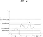
- an adjustment course adjusts the washing intensity stepwise, and controls a rotation time period of the drum itself to become greater when the washing intensity is higher than when the washing intensity is lower.
- the adjustment course may uniformly maintain a maximum rotation speed of the drum even when the washing intensity increases.
- the adjustment course may set an actual operating rate of the drum to become lower as the washing intensity increases.
- the present disclosure may allow the user to arbitrarily adjust the rotation speed of the drum and the actual operating rate of the drum rotation.
- the present disclosure may have the course that may also wash the laundry that is prone to wear and tear and damage such as the wool while preventing the wear and tear and the damage of the laundry.
- the present disclosure may have the user course that may also wash the laundry such as the wool in the range between the delicate course for the laundry such as the wool and the standard course.
- the present disclosure may have the course that allows the user to adjust the washing intensity or the like in steps in the user course.
- FIG. 2 shows an outer appearance of a laundry treating apparatus 100 of the present disclosure.
- the laundry treating apparatus 100 of the present disclosure may be equipped with one washing machine 10 or drying machine 20, may be equipped with a plurality of washing machines 10 or a plurality of drying machines 20 stacked or arranged inside a single cabinet, or may be equipped with the washing machine 10 and the drying machine 20 stacked or arranged inside the single cabinet.
- the laundry treating apparatus of the present disclosure may be equipped with any shape and any form as long as it is able to treat laundry.
- FIG. 2 shows an embodiment in which the laundry treating apparatus 100 of the present disclosure is equipped with the washing machine 10 that removes foreign substances from the laundry or the drying machine 20 that dries the laundry
- FIG. 2 shows an embodiment in which the laundry treating apparatus 100 of the present disclosure is equipped with the washing machine 10 that removes the foreign substances from the laundry and the drying machine 20 that removes moisture from the laundry together.
- the laundry treating apparatus of the present disclosure may include a first control panel P1 that provides an algorithm for performing one of a washing cycle of removing the foreign substances from the laundry with water and detergent, a rinsing cycle of removing the foreign substances from the laundry and the detergent, a dehydration cycle of removing water from the laundry using a centrifugal force or the like, a drying cycle of removing moisture from the laundry using at least one of air and steam, and a refreshing cycle of performing at least one of deodorization, wrinkle removal, and sterilization of the laundry using at least one of air and steam.
- the first control panel P1 may include a device that enables communication between a user and the laundry treating apparatus (including other electronic devices including the laundry treating apparatus).
- the communication between the user and the laundry treating apparatus may include a process in which the user inputs various control commands to the laundry treating apparatus, and a process in which the laundry treating apparatus transmits a response (feedback) to the control commands or information generated from the laundry treating apparatus to the user.
- the laundry treating apparatus 100 of the present disclosure may include a cabinet 1 forming the outer appearance.
- the first control panel P1 of the laundry treating apparatus of the present disclosure may include the first control panel P1 equipped on the cabinet 1 and capable of controlling one washing machine 10 or one drying machine 20.
- the first control panel P1 may be equipped to receive at least one of a power command of supplying or cutting off power to the laundry treating apparatus, a selection command of selecting an arbitrary course or option to treat the laundry, an execution command of executing the selected course or option, and a stop command of stopping the course or option being executed.
- the treatment of the laundry may include the washing cycle of removing the foreign substances from the laundry using water and the detergent, the drying cycle of drying water contained in the laundry, and the refreshing cycle of performing the deodorization and the wrinkle removal of the laundry using hot air and steam.
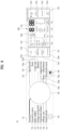
- the first control panel P1 may include a screen P8 that displays an operating state of the laundry treating apparatus or information on the course or the option to the user.
- the screen P8 may display a state in which at least one of the power command, the selection command, the execution command, and the stop command has been input.
- the screen P8 may display error information indicating a problem situation that has occurred in the laundry treating apparatus or guidance information guiding the user on what actions to take.
- the screen P8 may visually display the information.
- the screen P8 may include a liquid crystal display that radiates light to the outside.
- the first control panel P1 may include at least one of speakers capable of outputting voice signals and sounds.
- the cabinet 1 may include a front panel 13 forming a front side, and a top panel 11 coupled to an upper side of the front panel 13.
- the front panel 13 and the top panel 11 may be made of a metal material and may be formed in a steel plate shape.
- the first control panel P1 of the laundry treating apparatus of the present disclosure may be coupled to the front panel 13.
- the first control panel P1 may not be formed as a separate support panel and disposed on the front panel 13, but may be directly coupled to a rear surface of the front panel 13. The first control panel P1 may be exposed only partially to a front surface of the front panel 13.
- a ratio of an area occupied by the first control panel P1 in the front panel 13 may be minimized, and a sense of unity of the front panel 13 may be strengthened, so that aesthetics may be maximized.
- a process of manufacturing the front panel 13 may be simplified, and a process of assembling or installing the front panel 13 and the first control panel P1 may be simplified.
- a separate frame or the like for seating the first control panel P1 on the front panel 13 may be omitted.
- the rotary knob P7 may be formed in a form of the rotary knob, and the screen P8 may be formed as a display D including a liquid crystal display device or the like. It may be seen that the screen P8 and a selector R to be described below are included inside the rotary knob P7.
- the screen P8 may be formed entirely as a touch panel, or at least partially as the touch panel.
- the screen P8 may be equipped as a simple liquid crystal display so as not to receive separate commands and to only display information.
- the rotary knob P7 may be equipped to rotate on the front panel 13 such that an arbitrary course or option that may treat the laundry may be selected.
- the laundry treating apparatus of the present disclosure may omit description of the arbitrary course or option that may rotate a drum to be described below in a form of text, guidance text, and the like on the front panel 13. Accordingly, the area size or the ratio of the area size that the first control panel P1 occupies on the front panel 13 may be significantly reduced, and because no separate text or guidance text is attached to the front panel 13, the aesthetics may be maximized.
- the front panel 13 or the first control panel P1 may be prevented from being produced differently.
- the rotary knob P7 and the screen P8 may operate only when power is supplied thereto.
- the first control panel P1 of the laundry treating apparatus of the present disclosure may further include a power button P46 for inputting the power command to the laundry treating apparatus in addition to the rotary knob P7 and the display.
- the user may activate the rotary knob P7 by pressing the power button P46.
- the first control panel P1 may further include an execution button P47 for inputting the execution command to execute or stop the selected course or option.
- the execution button P47 may be formed separately from the rotary knob P7 and the screen P8 so as to receive a user's definite intent to execute or stop.
- the first control panel P1 may further include a setting area P19 that may add or change options to the course on the front panel 13.
- the user may set options that may change the intensity, a duration, and the like of the course via the setting area P19.
- the setting area P19 may include a liquid crystal display device separate from the screen P8.
- the setting area P19 may include a touch panel or a physical button that may input the options.
- the first control panel P1 may be equipped to be in communication with a controller that may operate the laundry treating apparatus, or may have the controller installed thereon.
- the controller may be formed in a shape of a PCB installed on the control panel P.
- the front panel 13 may include an inlet 111 that is in communication with the drum accommodated in the cabinet 1, and a door 14 that is pivotably coupled to the cabinet and opens and closes the inlet 111.
- the first control panel P1 may be positioned above the door 14 to enhance user accessibility.
- the front panel 13 may further include a lock L that fixes the door 14 to the front panel 13.
- the lock L may lock the door 14 to the front panel 13. This may prevent a safety accident.
- the lock L may unlock the door 14 when the laundry treating apparatus is finished operating.
- the lock L may be equipped as any component as long as it may fix the door 14 to the cabinet 1.
- the lock L may be equipped as a fastener that secures a hook protruding from the door, and may also be equipped as a solenoid valve that holds the hook.
- the front panel 13 may include a filter hole 24 through which a filter of the laundry treating apparatus may be replaced.
- the washing machine 10 may be equipped with a washing cabinet 1, and the drying machine 20 may include a drying cabinet 1A that may be seated or supported on the washing cabinet 1.
- washing machine 10 and the drying machine 20 may share one cabinet 1.
- the control panel P of the laundry treating apparatus of the present disclosure may include a second control panel P2 that may simultaneously control the washing machine 10 and the drying machine 20. As a result, the washing machine 10 and the drying machine 20 may share the second control panel P2. As a result, inconvenience of controlling the washing machine 10 and the drying machine 20 with the separate control panels P or installing the plurality of control panels P may be prevented.
- the second control panel P2 may receive a user's command via user's touch or the like without a separate physical button.
- the second control panel P2 may include a power area P25 that receives a command to supply the power to the washing machine 10 and the drying machine 20, a control area P22 that displays display states of the washing machine 10 and the drying machine 20, and an execution area P26 that receives a command to operate the washing machine 10 and the drying machine 20.
- the control area P22 may display only one of information of the washing machine 10 and the drying machine 20, and transmit the user's input to only one of the washing machine 10 and the drying machine 20.
- the second control panel P2 may further include a switching area P27 that switches a subject displayed on the control area P22 of the washing machine 10 and the drying machine 20, or switches the information input to the control area P22 to be transmitted to one of the washing machine 10 and the drying machine 20.
- the laundry treating apparatuses of the present disclosure may commonly include a sensor M that senses opening and closing of the door 14 in at least one of the door 14 and the cabinet 1.
- the sensor M may be equipped as any component as long as it may sense the opening and the closing of the door 14.
- the senor M may be composed of a magnet that generates a magnetic field disposed in the door 14, a hall sensor that is disposed in the cabinet 1 to sense a location of the magnet, and the like.
- FIG. 3 shows an internal structure of a laundry treating apparatus of the present disclosure when it is equipped as the washing machine 10.
- FIG. 3 is a perspective view of the washing machine 10 of the present disclosure
- FIG. 3 is a cross-sectional view of the washing machine 10 of the present disclosure.
- the washing machine 10 of the present disclosure may include the cabinet 1 that forms the outer appearance, a tub 2 accommodated in the cabinet 1 to store water, a drum 3 rotatably disposed in the tub 2 to store water, a driver 32 coupled to the tub 2 to rotate the drum 3, a water supply 23 that supplies water to the tub 2, and a drainage 25 that drains water from the tub 2.
- the driver 32 may include a stator 321 coupled to a rear side of the tub 2, a rotor 322 rotated by the stator 321, and a rotation shaft 323 coupled to the rotor 322 to rotate the drum 3.
- the water supply 23 may include a water supply pipe 231 that allows an external water source and the tub 2 to be in communication with each other, and a water supply valve 233 that opens and closes the water supply pipe 231.
- the water supply 23 may further include a detergent box 234 that may be extended forward of the cabinet 1 to allow the detergent to be injected into the tub 2, the water supply pipe 231 may be in communication with the detergent box 234, and the detergent box 234 may be connected to the tub 2 via a supply pipe 232.
- the drainage 25 may include a drainage pipe 251 disposed under the tub 2, a drainage pump 252 that is coupled to the drainage pipe 251 and provides power to discharge water, and a discharge pipe 253 that discharges water from the drainage pump 252 to the outside.
- the drying machine 20 of the present disclosure may include the drying cabinet 1A, a drum 3A rotatably disposed inside the cabinet to provide a space for storing the laundry, a circulation flow channel 4 that forms a flow channel for re-supplying air discharged from the drum 3A to the drum 3A, and a heat exchanger 5 that dehumidifies and heats air introduced into the circulation flow channel 4 and then re-supplies air to the drum 3A.
- the heat absorber 51 may be equipped as an evaporator that absorbs heat
- the heat generator 53 may be equipped as a condenser that releases heat.
- the water storage inlet 922 may receive water discharged from a nozzle 823A fixed to the cabinet 1A.
- the nozzle 823A may be fixed to the top panel 11 of the cabinet so as to be positioned upward of the water storage inlet 922 when the storage body 92 is inserted into the cabinet 1.
- the external water supply 500 may include a direct water valve 520 adjacent to or fixed to a rear panel 13, and a direct water pipe 510 that supplies water delivered from the direct water valve 520 to the steam unit 200.
- the direct water valve 520 may be coupled with the external water source.
- the direct water valve 520 may be coupled with a water supply pipe extending to a rear surface of the cabinet.
- the steam unit 200 may receive water directly via the direct water valve 520. Therefore, even when the internal water supply 400 is omitted or water is not stored in the internal water supply 400, the steam unit 200 may receive water via the direct water valve 520 whenever necessary.
- the direct water valve 520 may be directly controlled by a steam controller 800.
- the steam unit 200 may be disposed adjacent to the direct water valve 520, but may be disposed close to the front panel 13. As a result, steam may be supplied to a front side of the drum and evenly supplied to the entire laundry.
- the internal water supply 400 may include a water tank 420 that stores water, a water pump 430 that may supply water to the steam unit 200 by receiving water from the water tank 420, and a tank housing 410 that provides a space for seating the water tank 420 and the water pump 430.
- the water pump 430 and the water tank 420 may be disposed at a vertical level corresponding to the steam unit 200.
- a tank withdrawal hole 131 may be installed in an area corresponding to a portion where the water tank 420 is installed in the top panel 11. As a result, the water pump 430 may be prevented from being unnecessarily exposed to the tank withdrawal hole 131 as much as possible.
- a withdrawal cover 132 may be pivotably coupled to an outer peripheral surface of the tank withdrawal hole 131 to prevent the water tank 420 from being unnecessarily exposed to the outside.
- the steam unit 200 may be in communication with the drying drum 3A or the circulation flow channel 4 and supply steam into the drying drum 3A.
- the steam unit 200 may receive water via a water supply 300, generate steam, and then supply steam to the drying drum 3A or the duct 4 via a steam discharge pipe 213.
- the steam discharge pipe 213 may be in direct communication with the drying drum 3A to supply steam into the drying drum 3A, and may be in communication with the duct 4 or the second support 19 to indirectly supply steam into the drying drum 3A.
- the steam discharge pipe 213 may be in communication with the supply duct 43 when being connected to the duct 4, and may be in communication with the water storage inlet 922 when being connected to the second support 19A. As a result, steam may be more smoothly supplied into the drying drum 3A using the power of the blower fan 59.
- the steam unit 200 may be controlled to generate steam when a steam supply mode that uses steam is performed during the drying cycle.
- the steam supply mode may correspond to a series of drying courses of sterilizing the laundry, increasing a temperature inside the drum during the drying cycle of the laundry, or removing wrinkles from the laundry at an end of the drying cycle of the laundry.
- the steam unit 200 may be controlled to supply steam into the drying drum 3A or the like by receiving water via the internal water supply 400 as well as the external water supply 500 as needed.
- the heat exchanger 5 condenses moisture in air circulating in the heat absorber 51. Therefore, even when air circulates in the drying drum 3A, because moisture is removed in the heat absorber 51, the laundry inside the drying drum 3A may be continuously dried.
- Moisture condensed in the heat absorber 51 may be primarily collected in the water collector 47 and then secondarily collected in the water storage 9.
- the water collector 47 may be located inside the connecting duct 45, and may be formed separately in a space separated from the connecting duct 45.
- a rotation center of the drying drum 3A may be disposed between the steam unit 200 and the heat exchanger 5 based on a height direction of the cabinet.
- the heat exchanger 5 may be disposed downward of the rotation center of the drying drum 3A
- the steam unit 200 may be disposed upward of the rotation center of the drying drum, based on the height direction of the cabinet.
- the water collector 47 may be equipped as a water collecting body 471A fixed to a bottom surface of the connecting duct 45 and in communication with the inside of the connecting duct.
- a heat exchanging apparatus support 473A may be further disposed inside the water collecting body 471A.
- the heat exchanging apparatus support 473A may be equipped as a support plate on which the heat absorber 51 and the heat generator 53 come into contact.
- the heat exchanging apparatus support 473A may further include a spacer 475 that maintains a spacing between the support plate and a bottom surface of the water collecting body 471A, and a support plate through-hole 476 that extends through the support plate.
- the support plate through-hole 476 may be defined only in a space where the heat absorber 51 is supported in a space provided by the support plate, or may be defined in each of the space in which the heat absorber is supported and a space in which the heat generator is supported. When the support plate through-hole 476 is also defined in a lower portion of the heat generator 53, water that has flowed to the heat generator 53 along the support plate 373 may be discharged to the water collecting body 471.
- the laundry treating apparatus 100 may further include a filter that filters air.
- a second filter 7 may be disposed as a means for filtering air introduced into the exhaust duct 41 from the drum body 31, and a first filter 6 may be disposed as a means that is located between the second filter 7 and the heat absorber 51 and filters air that has passed through the second filter 7.
- a diameter of a filter hole defined in the first filter 6 may be set smaller than a diameter of a filter hole defined in the second filter 7.
- the first filter 6 may be detachably disposed in the connecting duct 45.
- a filter mounting hole through which the first filter 6 is withdrawn and a mounting hole door 14 for opening and closing the filter mounting hole may be disposed in the front panel 13 of the cabinet, and a duct through-hole 44 into which the first filter 6 is inserted may be defined in the duct 4.
- the user may remove the foreign substances remaining in the first filter 6 and wash the first filter after separating the first filter 6 from the laundry treating apparatus as needed.
- the laundry treating apparatus 100 may further include a washer 8 that washes the first filter 6 using water stored in the water collecting body 471. That is, water stored in the water collecting body 471 may be collected separately into the water storage 9 or may selectively flow to the washer 8.
- the washer 8 may be equipped as a means for washing the first filter 6 by spraying water stored in the water collecting body 471.
- the washer 8 may include a spray 85 that is disposed in the duct 4 to supply water to the first filter 6, and a washing pump 81 that allows water stored in the water collection body 471 to flow to the spray 85.
- each of the pump discharge pipe 433 and the direct water pipe 510 may be equipped with a check valve.
- the external water supply 500 may be equipped with an external check valve
- the internal water supply 400 may be equipped with an internal check valve.
- the power button P46 may include a first button 461 exposed to the outside of the cabinet 1, a first sensor 464 fixed to the first circuit board P4, and a conductor (a first touch spring) 463 connecting the first button with the first sensor.
- the execution button P47 may include a second button 471 exposed to the outside of the cabinet 1, a second sensor 474 fixed to the first circuit board P4, and a conductor (not shown, a second touch spring) connecting the second button with the second sensor.
- the front panel 13 includes a first button mounting portion 136 and a second button mounting portion 117.
- the first button 461 may be exposed to the outside of the cabinet 1 via the first button mounting portion 116
- the second button 471 may be exposed to the outside of the cabinet 1 via the second button mounting portion 117.
- the power button P46 and the execution button P47 may be disposed separately in left and right spaces of the screen P8, may be disposed separately in upper and lower spaces of the display, or may be disposed vertically or horizontally in either the left or right space of the display.
- the first touch spring 463 and the second touch spring may be formed in a coil shape, which is intended to provide a restoring force to the first button 461 and the second button 471. Furthermore, to prevent the first button 461 and the second button 471 from being deviated from the respective button mounting portions 116 and 117, the power button 46 may include a first stopper 462 that limits a range of motion of the first button, and the execution button 47 may include a second stopper (not shown) that limits a range of motion of the second button.
- the encoder P5 is a means for rotatably fixing the manipulator P7 to the first circuit board P4, and also is a means for generating an electric signal when the rotary knob P7 is rotated (or generating an electric signal set differently based on a rotation angle of the actuator).
- the encoder P5 may include a fixed portion P51 fixed to the first circuit board P4 and to which the screen P8 is fixed, a rotatable portion P52 rotatably disposed on the fixed portion P51 and to which the rotary knob P7 is fixed, and a signal generator P54 that generates the electric signal when the rotatable portion P52 is rotated.
- the encoder cover P7 may be formed in a pipe shape that is fixed to the first circuit board P4 and surrounds the encoder P5. That is, as shown in the drawing, the encoder cover P6 may include a fixed body cover P61 that is fixed to the first circuit board P4 and surrounds the fixed body 512, and a cover through-hole P62 that extends through the fixed body cover P61 and into which the encoder 5 is inserted.
- the encoder cover P6 may further include a support body cover P63 that extends from the fixed body cover P61 and surrounds the rotatable portion P52 (surrounds the support body). Because the support body cover P63 may restrict the rotary knob P7 from moving in a radial direction of the cover through-hole 62, the support body cover 63 may prevent the rotary knob P7 from being separated from the rotatable portion P52.
- the cover panel P21 may be coupled to the cabinet 1 to prevent the control board P24 and the liquid crystal display P22 from being exposed to moisture or colliding directly with an external object or the like.
- a touch film P23 may be further disposed such that the display liquid crystal P22 may perform a function of a touch panel.
- the touch film P23 may be equipped as a transparent thin film that is equipped to sense not only the current received from the user's body, but also coordinates to which the current has reached.
- the control board P24 may include a display controller P241 electrically connected to the liquid crystal display P22, and a touch receiver P242 electrically connected to the touch film P23.
- the touch film P23 may have an area size corresponding to that of the liquid crystal display P22, and may transmit, to the touch receiver P242, whether the user's body is in contact with or close to the coordinates displayed in the touch information.
- the second control panel P2 of the present disclosure has the power area P25 and the execution area P26 disposed separately from the control board P24 to clearly distinguish the touch of the power area P25, the touch of the execution area P26, and the touch of the display liquid crystal display P22 from each other.
- the power area P25 may be equipped as a PCB that is disposed separately from the control board P24 and senses a user's touch, and the power area P25 may include a light-emitter that may irradiate light to the cover panel P21.
- the execution area P26 may be equipped as a PCB that is disposed separately from the control board P24 and senses a user's touch, and the execution area P26 may include a light-emitter that may irradiate light to the cover panel P21.
- the power area P25 and the execution area P26 may not be equipped as liquid crystal displays, but may be equipped as circuit boards that may sense input of current, and may include the light-emitters for guiding touch areas.
- the second control panel P2 of the present disclosure may further include a support panel P28 that supports the power area P25, the execution area P26, and the control board P24, and provides a space for seating the liquid crystal display P22 and the touch film P23.
- the support panel P28 may be made of a resin-based material, and may be formed in a shape that may accommodate and support the power area P25, the execution area P26, and the control board P24.
- the support panel P28 may accommodate and support outer peripheral surfaces of the liquid crystal display P22 and the touch film P23.
- a fixing panel P29 that may be coupled to a rear side of the support panel P28 and fix the power area P25, the execution area P26, the control board P24, the liquid crystal display P22, and the touch film P23 may be included.
- the fixing panel P29 may be coupled to the support panel P28 via a fastening member such as a bolt.
- the support panel P28 may be coupled to and fixed to a frame or the like forming the cabinet 1, or may be fixed by being seated on a bent surface formed by bending an outer peripheral surface of the cover panel P21.
- control panel P of the present disclosure may be equipped as one of the first control panel P1 including a rotary knob and a screen and the second control panel P2 equipped in a touch panel manner, depending on the form of the laundry treating apparatus.
- control panel P of the present disclosure may be equipped as a third control panel P3 to be described later, which has all components that receive the user input as physical buttons and displays visual information with a light-emitter like a simple bulb.
- control panel P of the present disclosure may be equipped with various structures, but the control panel P of the present disclosure may perform a role of an interface I that receives a user's command, displays information to the user, and is in communication with the user in the laundry treating apparatus 100.
- control panel P of the present disclosure may be distinguished by centered on the fact that it performs the role or function of the interface I rather than the structure thereof.
- FIG. 7 shows an embodiment of the first control panel P distinguished to be the interface I.
- the first control panel P of the present disclosure may include a power unit 710 that receives a power command for supplying power to the laundry treating apparatus or the control panel P, a course selector 710 that receives a selection command of selecting an arbitrary course that may perform the treatment of the laundry, an option selector 730 that receives a selection command of an arbitrary option of selecting conditions of the course, and an execution unit 740 that receives an execution command for performing the selected course and option.
- a power unit 710 that receives a power command for supplying power to the laundry treating apparatus or the control panel P
- a course selector 710 that receives a selection command of selecting an arbitrary course that may perform the treatment of the laundry
- an option selector 730 that receives a selection command of an arbitrary option of selecting conditions of the course
- an execution unit 740 that receives an execution command for performing the selected course and option.
- the course for treating the laundry may be viewed as a series of control methods that may perform one of the washing cycle of removing the foreign substances from the laundry with water and detergent, the rinsing cycle of removing the foreign substances from the laundry and the detergent, the dehydration cycle of removing water from the laundry using the centrifugal force or the like, the drying cycle of removing moisture from the laundry using at least one of air and steam, and the refreshing cycle of performing at least one of the deodorization, the wrinkle removal, and the sterilization of the laundry using at least one of air and steam.
- the power button P46 may be defined as the power unit 710
- the execution button P47 may be defined as the execution unit 740
- the rotary knob P7 may be defined as the course selector 710
- the setting area P19 may be defined as the option selector 730.
- the option selector 730 may be equipped as a touch display that may select the arbitrary option, and may be equipped with a plurality of lamps and a plurality of conductor switches that may sense the user's body.
- the content display 820 may display the state and the function of the laundry treating apparatus in detail and variably. Therefore, the content display 820 may be larger than the state display 810.
- the course and the option may be selected via the touch film P23. Therefore, the touch film P23 may be defined as the course selector 720 and the option selector 730.
- the power unit 710 may include a first power unit 711 that receives a power command of the washing machine 10 and a second power unit 712 that receives a power command of the drying machine 20.
- the switching unit 750 may be disposed between the power unit 710 and the display 800.
- the liquid crystal display P22 and the touch film P23 are disposed to overlap each other. As a result, it may be seen that the display 800 and the input unit 710 are divided from each other based on a display area of the liquid crystal display P22.
- a lower area may be defined such that the course and the option are selected, and an upper area and a central area may be defined to display various information.
- the upper area may perform a role of the state display 810, and the central area may perform a role of the content display 820.
- the information on the sensed laundry or amount of laundry, the specific details of the selected course or option, the state in which the course or the option is being executed, and the guidance information required for the user may be displayed as the text or image 821.
- the information on the laundry or the amount of laundry displayed on the content display 820 may include the information on the weight of the laundry and the amount of detergent required to treat the laundry.
- the content of the selected course displayed on the content display 820 may include the type of course suitable for treating the laundry of the specific material or the specific load (what to wash), the duration of the course, the remaining time of the course, and the like. Therefore, the content display 820 may perform the role of the course display.
- the content of the selected option displayed on the content display 820 may be the information on how to execute the course (how to wash), such as the number of repetitions of cycles of washing, rinsing, dehydration, and the like performed in the course, the intensity of the cycle, the temperature at which the cycle is performed, and the like.
- the content display 820 may also serve as the option display.
- the lower area of the display 800 receives the selection of the course/option, it may be viewed as performing the role of the input display 830.
- the course selector 720 may be displayed at a left lower end of the liquid crystal display P22.
- the liquid crystal display P22 may switch to display various courses provided by the laundry treating apparatus of the present disclosure, scattered across at least one of the content display 820, the state display 810, and the input display 830, and the specific course may be selected by sensing that a specific area of the touch film P23 is pressed.
- the option selector 730 may be disposed on one side of the course selector 720 on the liquid crystal display P22.
- optional conditions that may be changed may be displayed in a scattered manner on at least one of the content display 820, the state display 810, and the input display 830 of the liquid crystal display P22, and the option may be changed by sensing that a specific area of the touch film P23 is pressed.
- the lower area 830 displays content corresponding to the option, it may be considered to also perform the role of the option display 840.
- the additional function unit 739 may be equipped as a separate input unit. When the additional function unit 739 is pressed, the washing unit 736, the reservation manager 737, and the sterilization unit 738 may be displayed together on the display 800, so that the additional function of the course may be input to the touch film P23.
- the display 800 may further include a switching display 850 that indicates whether the information currently displayed on the display 800 is related to either the washing machine 10 or the drying machine 20.
- the display 800 may display the information related to the washing machine 10 that is disposed at the bottom.
- the third control panel P3 of the present disclosure may include the input unit 700 including the power unit 710 that receives the power command for supplying the power to the laundry treating apparatus or the control panel P, the course selector 710 that receives the selection command for selecting the arbitrary course capable of performing the laundry treatment, the option selector 730 that receives the selection command of the arbitrary option for selecting the conditions of the course, and the execution unit 740 for receiving the execution command for executing the selected course and option.
- Functions of the respective components of the input unit 700 of the third control panel P3 may be the same as those of the input unit 700 of the first control panel P1.
- the third control panel P3 may further include the display 800 that may display the information corresponding to the input of the input unit 700 to the user or may visually the display guidance information for the user, the state information of the laundry treating apparatus, and the like to the user.
- the function of the display 800 of the third control panel P3 may be the same as that of the display 800 of the first control panel P1.
- the third control panel P3 may be equipped with the power unit 710 and the execution unit 740 as separate buttons.
- the control panel P3 may be equipped with the course selector 720 as a rotary knob.
- the course selector 720 may be disposed between the power unit 710 and the execution unit 740, and a name of a course corresponding to each tick of the rotary knob's rotational steps may be printed on a surface of the third control panel P3 on the outside of the rotary knob.
- the display 800 may be disposed to be spaced apart from the course selector 720.
- the option selector 730 may be equipped as a separate button combination by being spaced apart from the course selector 720, and may be disposed along a perimeter of the display 800.
- the course selector 720 may include a standard course unit 721 that selects a standard course to treat the laundry with appropriate intensity and appropriate temperature condition by selecting an average material of the entire laundry that users generally treat.
- the average material may be cotton or a T-shirt material
- the appropriate intensity may be an intensity that corresponds to a middle level among those provided by the laundry treating apparatus
- the appropriate temperature condition may be a cold water condition.
- the course selector 720 may further include an intensive course unit 722 of selecting a stained clothes course that treats the laundry with higher strength and higher temperature condition than the standard course, a baby clothes course unit 723 of selecting a baby clothes course that treats laundry made of a softer material than that of the standard course, a boiling course unit 724 of selecting a boiling course that treats the laundry for a longer time than the standard course using hot water or the heater H1, a functional course unit 725 of selecting a functional course that treats functional laundry such as waterproof or Gore-Tex laundry, an allergy course unit 726 of selecting an allergy care course that performs the sterilization by exposing the laundry to a high temperature equal to or higher than 50 degrees for a sterilization time of 10 minutes or longer, a steam course unit 727 of selecting a steam course that supplies steam to the laundry by heating water via the heater H1 or the like, a speed course unit 728 of selecting a quick course that treats the laundry with a shorter execution time than the standard course, a quiet course unit 729 of selecting a quiet course that treats the laundry
- the surface of the third control panel P3 may display the type of course corresponding to the course selector 720.
- the type of course may be indicated by being printed, or the type of course specified via the course selector 720 may be indicated by being illuminated in a manner such as a light bulb. Therefore, it may be seen that the surface of the third control panel P3 performs the role of the course display.
- the option selector 730 may include the washing adjustor 734 that may select a washing intensity of the laundry, the rinsing adjustor 731 that may select a rinsing intensity of the laundry, the dehydration adjustor 732 that may select a dehydration intensity of the laundry, and the temperature adjustor 733 that may select a temperature condition of the laundry, as condition setting units.
- the option display 840 may be disposed upward of the washing adjustor 734, the rinsing adjustor 731, the dehydration adjustor 732, and the temperature adjustor 733 to externally display the cycle conditions selected via the option selector 730.
- the option selector 730 may include, as function setting units 739, a steam unit 7395 of selecting a steam option that supplies steam into the drum 3, a smart care unit 7396 of selecting a remote control option that performs the course with an external terminal, a reservation manager 7397 of selecting an option for setting a start time or an end time of the course, a tub sterilization unit 7398 of selecting an option that cleans and sterilizes the drum 3 and the tub 2 with high-temperature water and a rotational force of the drum, a turbo shot unit 7391 of selecting an option that generates a strong water flow inside by rotating the drum faster in the washing cycle and the rinsing cycle, a user setting unit 7392 of selecting an option to treat the laundry with washing intensity, rinsing intensity, and dehydration intensity specified by the user, an anti-wrinkle unit 7393 of selecting an option to prevent wrinkling of the laundry by intermittently rotating the drum after the course ends, a laundry addition unit 7394 of selecting an option
- the display 800 may include the state display 810 and the content display 820 described above.
- the state display 810 may display the current state of the laundry treating apparatus with various icons as described above, and the content display 820 may display information 821 such as a progress time or expected time of the course, or a reservation time in text, numbers, images, or the like.
- the content display 810 of the third control panel P3 may be equipped with a plurality of light bulbs that turn on or off respective corresponding areas, rather than a liquid crystal display that displays the screen variably.
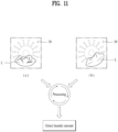
- FIG. 10 shows an aspect of a laundry treating apparatus of the present disclosure sensing an amount of laundry based on the above-described configuration.
- the laundry treating apparatus of the present disclosure may perform the laundry amount sensing before the execution unit 740 is pressed.
- the laundry treating apparatus of the present disclosure may sense the amount of laundry by rotating the drum 3 when the power unit 710 is pressed or the opening/closing of the door 14 is sensed.
- the drum 3 may be immediately rotated less than once to sense the amount of laundry.
- the drum 3 is rotated less than once, even when the user inputs the laundry with the door 132 open, the amount of laundry may be sensed without a possibility of the user being injured or the laundry being damaged.
- the laundry may be disposed on the bottom surface of the drum 3 because of an own weight thereof.
- the laundry treating apparatus of the present disclosure may rotate the drum 3 less than once.
- the laundry treating apparatus of the present disclosure may rotate the drum 3 by an angle equal to or smaller than an angle at which the laundry is separated from the drum inner wall or an arrangement thereof is changed. As a result, unnecessary load or impact may be prevented from being transmitted to the driver 32 as the location of the laundry changes inside the drum 3.
- the laundry treating apparatus of the present disclosure may rotate the drum in a range of 0 degrees to 90 degrees when sensing the amount of laundry.
- the laundry treating apparatus of the present disclosure may rotate the drum 3 in a range of 10 degrees to 45 degrees when sensing the amount of laundry.
- the laundry treating apparatus of the present disclosure may sense the amount of laundry quickly and accurately.
- the laundry treating apparatus of the present disclosure may sense the amount of laundry immediately and display information related to the amount of laundry on the display 800 when sensing the pressing of the power unit 710 or the opening/closing of the door 14 before the execution unit 740 is pressed.
- the controller C may calculate (process) the amount of laundry based on the current value.
- the controller C may calculate the torque value applied to the driver 32 when it senses the current value I.
- sin ⁇ in mgrsin ⁇ , because the value decreases exponentially as the rotation angle of the drum decreases, sin ⁇ may be sufficiently ignored when the rotation angle is in a range of 15 degrees to 90 degrees or in a range of 10 degrees to 45 degrees.
- Bw is a friction torque, and is able to be ignored because B becomes very small when the drum 3 rotates.
- the controller C may sense the angular acceleration in the process of rotating the drum when sensing the amount of laundry.
- the angular acceleration may be directly calculated via the current value applied to the driver 32. A method of calculating the angular acceleration with the current value will be described later.
- both the torque value Te applied to the driver 32 and the angular acceleration dw/dt may be calculated by measuring the current value, a moment of inertia J may be calculated.
- the laundry treating apparatus of the present disclosure may immediately sense the amount of laundry by identifying the moment of inertia J.
- FIG. 12 shows a basic structure in which the controller C may measure the current value of the driver 32 in the laundry treating apparatus of the present disclosure.
- the controller C may control the driver 32 by applying current to the driver 32, and may sense the current discharged from the driver 32.
- the controller C controls the driver 32 based on a preset course or option, and the driver 32 rotates the drum 3 in response to a command of the controller C.
- the controller C operates by receiving an operation signal or a control command from the course selector 720, the execution unit 740, or the option selector 730. Washing course and option to perform the washing, rinsing, and dehydration cycles may be selected via the course selector 720 or the option selector 730.
- the washing, rinsing, and dehydration cycles may be performed.
- the controller C may control the display 800 to display the washing course, the washing time, the dehydration time, the rinsing time, the current operation state, or the like.
- the controller C may control the driver 32 to rotate the drum 3 and also vary the rotation speed of the drum 3. Specifically, the controller C may control the driver 32 based on at least one of a current detector 225 that detects an output current flowing through the driver 32 and a location sensor 220 that senses a location of the driver 320. For example, either the current detected by the driver 32 or the sensed location signal may be fed back to the controller C, and the controller C may generate a current signal that may appropriately control the driver 32 based on the feedback signal.
- the laundry treating apparatus of the present disclosure may sense the location of the driver 32 by omitting the location sensor 235 and implementing a separate algorithm (as known as a sensorless driver).
- the sensorless driver 32 may be constructed to identify a location of the rotor or the stator as the controller C measures the current or voltage output from the driver 32.
- the driver P may be equipped as a three-phase motor such that the rotation speed thereof may be controlled, and may be equipped as, for example, a BLDC motor.
- the controller C may include an inverter 420 and an inverter controller 430 to control the aforementioned rotor and stator.
- the controller C may further include a converter 410 that supplies DC power to be input to the inverter 420, or the like.
- the controller C may also perform a role of the inverter controller 430 at the same time.
- the inverter controller 430 may be formed separately from the controller C.
- the inverter controller 430 outputs a switching control signal Sic in a pulse width modulation (PWM) scheme to the inverter 420
- the inverter 420 may perform a high-speed switching operation to supply AC power of a predetermined frequency to the rotor 913 and the stator 911.
- PWM pulse width modulation
- the laundry treating apparatus of the present disclosure may further include, in addition to the converter 410, the inverter 420, and the inverter controller 430, a DC terminal voltage detector B, a smoothing capacitor C, and an output current detector E.
- the laundry treating apparatus of the present disclosure may further include an input current detector A, a reactor L, and the like.
- the reactor L is disposed between a commercial AC power source (vs) 405 and the converter 410, and performs a power factor correction or boosting operation.
- the reactor L may also perform a function of limiting harmonic current caused by high-speed switching of the converter 410.
- the input current detector A may detect an input current is input from the commercial AC power source 405. To this end, a current transformer (CT), a shunt resistor, and the like may be used as the input current detector A.
- CT current transformer
- the detected input current is may be input to the inverter controller 430 as a discrete signal in a form of a pulse.
- the converter 410 converts power from the commercial AC power source 405 that has passed through the reactor L into DC power and outputs the DC power.
- the commercial AC power source 405 is shown as a single-phase AC power source, but is also able to be a three-phase AC power source.
- An internal structure of the converter 410 also varies depending on a type of commercial AC power 405.
- the converter 410 may be composed of diodes or the like without a switching element, and may perform a rectification operation without a separate switching operation.
- the converter 410 may be composed of diodes or the like without a switching element, and may perform a rectification operation without a separate switching operation.
- four diodes may be used in a bridge form, and in a case of the three-phase AC power source, six diodes may be used in the bridge form.
- a half-bridge-type converter in which two switching elements and four diodes are connected may be used, and in the case of the three-phase AC power source, six switching elements and six diodes may be used.
- a boost operation, power factor improvement, and DC power conversion may be performed via the switching operation of the corresponding switching element.
- the smoothing capacitor C smooths the input power and stores the same.
- one element is exemplified as the smoothing capacitor C, but a plurality of elements may be disposed to secure element stability.
- the converter 410 may be connected to an output terminal, but the DC power may also be input directly.
- DC power from a solar cell may be input directly to the smoothing capacitor C or may be input after DC-to-DC conversion. Because the DC power is stored across the smoothing capacitor C, two terminals of the smoothing capacitor C may also be referred to as DC terminals or DC link terminals.
- the DC terminal voltage detector B may detect a DC terminal voltage Vdc at both terminals of the smoothing capacitor C. To this end, the DC terminal voltage detector B may include a resistance element, an amplifier, and the like. The detected DC terminal voltage Vdc may be input to the inverter controller 430 as a discrete signal in a form of a pulse.
- the inverter controller 430 may control the switching operation of the inverter 420. To this end, the inverter controller 430 may receive an output current io detected by the output current detector E.
- the output current detector E may be located between the inverter 420 and the driver 32, and a current transformer (CT), a shunt resistor, and the like may be used for the current detection.
- CT current transformer
- a shunt resistor When the shunt resistor is used, three shunt resistors may be located between the inverter 420 and the driver 32, or respective terminals thereof may be respectively connected to the three lower-arm switching elements S'a, S'b, and S'c of the inverter 420.
- two shunt resistors may also be used.
- the corresponding shunt resistor may be disposed between the capacitor C described above and the inverter 420.
- the detected output current io as a discrete signal in a form of a pulse, may be applied to the inverter controller 430, and the inverter switching control signal Sic is generated based on the detected output current io.
- the detected output current io corresponds to the three-phase output currents ia, ib, and ic.
- the three-phase driver 32 has a stator and a rotor, and three-phase AC voltage with a specific frequency is applied to coils of respective phases a, b, and c of the stator, causing the rotor to rotate.
- Such driver 32 may include a surface-mounted permanent-magnet synchronous motor (SMPMSM), an interior permanent magnet synchronous motor (IPMSM), a synchronous reluctance motor (Synrm), and the like.
- SMPMSM surface-mounted permanent-magnet synchronous motor
- IPMSM interior permanent magnet synchronous motor
- Synrm synchronous reluctance motor
- the SMPMSM and the IPMSM are permanent magnet synchronous motors (PMSM), and the Synrm does not have a permanent magnet.
- the inverter controller 430 may control the switching operation of the switching element in the converter 410 when the converter 410 includes the switching element. To this end, the inverter controller 430 may receive the input current is detected by the input current detector A. Further, the inverter controller 430 may output a converter switching control signal Scc to the converter 410 to control the switching operation of the converter 410. Such converter switching control signal Scc, as a switching control signal in a pulse width modulation (PWM) scheme, may be generated and output based on the input current is detected from the input current detector A.
- PWM pulse width modulation
- the location sensor 235 may sense a rotor location of the driver 32.
- the location sensor 235 may include a hall sensor.
- the sensed rotor location H is input to the inverter controller 430 and used as basis for speed calculation and the like.
- FIG. 12 shows an embodiment of a specific circuit structure in which the inverter controller 430 controls the driver 32.
- the inverter controller 430 may include an axis converter 510, a speed calculator 520, a current command generator 530, a voltage command generator 540, an axis converter 550, and a switching control signal output unit 560.
- the axis converter 510 may receive the three-phase output currents ia, ib, and ic detected by the output current detector E and converts them into two-phase currents i ⁇ and i ⁇ of a stationary coordinate system.
- the axis converter 510 may convert the two-phase currents i ⁇ and i ⁇ of the stationary coordinate system into two-phase currents id and iq of a rotating coordinate system.
- the speed calculator 520 may calculate the speed based on the location signal H of the rotor input from the location sensor 235. That is, the speed may be calculated by dividing the location signal by time. The speed calculator 520 may output the calculated location and the calculated speed based on the input location signal H of the rotor.
- the current command generator 530 generates a current command value i*q based on a calculated speed w and a speed command value ⁇ *r.
- a PI controller 535 may perform PI control based on a difference between the calculated speed w and the speed command value ⁇ *r, and generate a current command value iq.
- a q-axis current command value i*q is exemplified as the current command value, but unlike the drawing, a d-axis current command value i*d may also be generated together.
- a value of the d-axis current command value i*d may be set to 0.
- the current command generator 530 may further include a limiter (not shown) that limits a level of the current command value i*q so as not exceed an allowable range.
- the voltage command generator 540 generates d-axis and q-axis voltage command values v*d and v*q, based on d-axis and q-axis currents id and iq axis-converted into a two-phase rotating coordinate system by the axis converter, and current command values i*d and i*q in the current command generator 530 or the like.
- the voltage command generator 540 may perform the PI control in the PI controller 544 and generate the q-axis voltage command value v*q based on a difference between the q-axis current iq and the q-axis current command value i*q.
- the voltage command generator 540 may perform the PI control in the PI controller 548 and generate the d-axis voltage command value v*d, based on a difference between the d-axis current id and the d-axis current command value i*d.
- a value of the d-axis voltage command value v*d may be set to 0 in response to the case in which the value of the d-axis current command value i*d is set to 0.
- the voltage command generator 540 may further include a limiter (not shown) that limits a level of the d-axis and q-axis voltage command values v*d and v*q so as not to exceed an allowable range.
- a limiter (not shown) that limits a level of the d-axis and q-axis voltage command values v*d and v*q so as not to exceed an allowable range.
- the generated d-axis and q-axis voltage command values (v*d and v*q are input to the axis converter 550.
- the axis converter 550 receives a location Q calculated by the speed calculator 520 and the d-axis and q-axis voltage command values v*d and v*q, and performs axis conversion. First, the axis converter 550 performs conversion from the two-phase rotating coordinate system to the two-phase stationary coordinate system. In this regard, the location Q calculated by the speed calculator 520 may be used.
- the axis converter 550 performs conversion from the two-phase stationary coordinate system to a three-phase stationary coordinate system. Via such conversion, the axis converter 1050 outputs three-phase output voltage command values v*a, v*b, and v*c.
- the switching control signal output unit 560 generates and outputs the inverter switching control signal Sic based on the pulse width modulation (PWM) scheme based on the three-phase output voltage command values v*a, v*b, and v*c.
- PWM pulse width modulation
- the output inverter switching control signal Sic may be converted into a gate operating signal by a gate driver (not shown) and may be input to a gate of each switching element in the inverter 420.
- a gate driver not shown
- each of the switching elements Sa, S'a, Sb, S'b, Sc, and S'c in the inverter 420 performs the switching operation.
- the switching control signal output unit 560 may generate and output the inverter switching control signal Sic that mixes a two-phase pulse width modulation scheme and a three-phase pulse width modulation scheme in relation to the embodiment of the present disclosure.
- the inverter switching control signal Sic in the three-phase pulse width modulation scheme may be generated and output, and in a constant-speed rotation period, the inverter switching control signal Sic in the two-phase pulse width modulation scheme may be generated and output to detect a counter electromotive force.
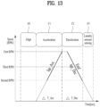
- the laundry treating apparatus of the present disclosure may perform a sensing step F of sensing the amount of laundry inside the drum 3 before performing the washing cycle, before performing the rinsing cycle, and before performing the dehydration cycle.
- the acceleration measurement value and the deceleration measurement value may be command values applied to the driver 32 while operating the driver 32, or may be measurement values measured by the driver 32 while operating the driver 32.
- the laundry treating apparatus of the present disclosure may significantly shorten a time required to sense the amount of laundry by omitting a step of maintaining operation of the driver 32 at a constant speed.
- the laundry treating apparatus of the present disclosure may save not only the process of maintaining the driver 32 at the constant speed, but also energy and time required to maintain the constant speed. In addition, the laundry treating apparatus of the present disclosure may completely ignore a frictional force of the driver 32 itself that should be overcome when maintaining the driver 32 at the constant speed in the calculation process.
- the controller C When the controller C senses the amount of laundry and uses the command value, the controller C does not need to feed back an actual situation to the driver 32 or consider an actual operating situation of the driver 32. Therefore, it may become simple and easy for the controller C to calculate the laundry amount value. In addition, because a calculation formula for calculating the amount of laundry becomes simple, the laundry amount value may be obtained quickly.
- the acceleration measurement value may include an acceleration current value Iq_Acc measured by the driver 32
- the deceleration measurement value may include a deceleration current value Iq_Dec measured by the driver 32.
- the acceleration current value may include a current command value Iq*_Acc for rotating the driver 32 during the acceleration step
- the deceleration current value may include a current command value Iq*_Dec for rotating the driver 32 during the deceleration step.
- the command value occurs only when the driver 32 is operated or is actively controlled by being powered. Therefore, when the measurement value is used, there is an advantage that data for sensing the amount of laundry may be obtained even when the power to the driver 32 is cut off or the driver 32 is not actively controlled.
- the laundry treating apparatus of the present disclosure may decelerate the driver 32 in a dynamic braking scheme or the like by cutting off the power in the deceleration step F2. Therefore, an algorithm for controlling the deceleration step F2 may be omitted, and energy for the deceleration step F2 may be saved.
- the voltage command value may be O. Therefore, in the present disclosure, the amount of laundry may be sensed via calculation only with the current, excluding the voltage.
- the method for controlling the laundry treating apparatus of the present disclosure may ignore or not use the voltage command value or the voltage value itself, and only use the current value, so that the calculation formula for sensing the amount of laundry may be very simple. Because the calculation formula is simple, the calculation may be performed quickly and accurately, so that the amount of laundry may be sensed accurately.
- calculation formulas data and algorithms for calculating the acceleration measurement value and the deceleration measurement value may be stored in the controller C.
- the calculation formula may not use the voltage value from the beginning. Accordingly, because there is no need to calculate the counter electromotive force, in the present disclosure, the constant-speed rotation step of the driver 32 may be omitted.
- calculation formula of the present disclosure may be provided as follows.
- the P and Ke are constant values of the driver 32 itself, which may be measured by the controller C, and a denominator corresponds to a difference between a speed change amount in the acceleration step and a speed change amount in the deceleration step.
- the speed change amount may be measured by the controller C because of the location sensor 235, calculated by measuring a time until the acceleration or the deceleration is performed, or immediately sensed by measuring the current or the like.
- the amount of laundry may be immediately calculated by only measuring an acceleration output current value Iq_Acc when accelerating and a deceleration output current value Iq_Dec when decelerating. That is, the acceleration current value may be considered to include the acceleration output current value Iq_Acc output from the driver during the acceleration step, and the deceleration current value may be considered to include the deceleration output current value Iq_Dec output from the driver during the deceleration step.
- an average value Iqe_Acc of the current values measured by the driver during the acceleration step may be applied to the acceleration output current value
- an average value Iqe_Dec of the current values measured by the driver during the deceleration step may be applied to the deceleration output current value
- the amount of laundry may be calculated with only one factor, the current value, and a factor of the voltage value may be omitted, so that the laundry amount calculation may become simplified and calculation speed and accuracy of the amount of laundry may be improved.
- the amount of laundry may be accurately sensed, so that a time required for the laundry amount sensing itself may be further reduced.
- the laundry treating apparatus of the present disclosure measures the amount of laundry by performing the deceleration immediately after the acceleration. Therefore, the time required for measuring the amount of laundry itself is very short, and the laundry inside the drum 3 is not able to move during the time. Therefore, because the amount of laundry may be sensed in a short period of time while the state of the laundry does not change, the accuracy of the laundry amount calculation may be further increased.
- the calculation formula applied to the laundry amount sensing in the present disclosure uses the difference between the current value in the acceleration step and the current value in the deceleration step. Therefore, a frictional force of the driver in the acceleration step and a frictional force of the driver in the deceleration step become equal to each other, so that current compensation formulas considering the frictional forces cancel each other. Therefore, the laundry amount sensing control method of the laundry treating apparatus of the present disclosure does not need to consider the frictional force of the driver 32, so that a process of compensating for or tuning the frictional force may be omitted.
- the laundry amount sensing in the present disclosure does not use the voltage value, a process of compensating for or tuning an error of the voltage value may be omitted, and because the constant speed process is omitted, a process of compensating for or tuning the movement of the laundry and the frictional force of the driver 32 may be omitted.
- the laundry amount sensing control method of the laundry treating apparatus of the present disclosure may sense the amount of laundry very quickly and accurately because the amount of laundry is derived immediately when the current value is input, and there is no procedure for compensating for or tuning the amount of laundry.
- an amount of load on the controller C may be reduced, the controller C may be replaced with a relatively simple configuration, or a performance of the controller C may be utilized in other ways.
- the acceleration measurement value may further include the speed change amount of the acceleration step F1
- the deceleration measurement value may further include the speed change amount of the deceleration step F2.
- the speed change amount of the acceleration step F1 and the speed change amount of the deceleration step F2 are only necessary to obtain a difference between inertia of the acceleration step F1 and inertia of the deceleration step F2. Separate measurement of the voltage value or the like may not be necessary, and furthermore, compensation or tuning processes may not be necessary.
- the method for controlling the laundry treating apparatus of the present disclosure senses the amount of laundry by performing the acceleration step F1 and the deceleration step F2 and using the current command value or the current value measured by the driver 32.
- the deceleration step F2 may be performed first, and then the acceleration step Bb may be performed to measure the current value and sense the amount of laundry via the same calculation formula.
- the sensing step F3 may perform a preparatory step F0 of checking the location of the driver 32 to set a reference value for performing the acceleration step F1 and the deceleration step F2.
- the drum 4 may be in a stationary state.
- the acceleration step F1 may additionally accelerate the drum, which is stationary in the preparation step FO, to a first rpm, and the deceleration step F2 may decelerate the drum from the first rpm. That is, the acceleration step F1 and the deceleration step F2 may be performed continuously. Because the deceleration step F2 simply involves lowering the current command value toward the driver 32 in the acceleration step F1 or cutting off the voltage applied to the driver 32, there is no concern about damage to the controller C or the circuit.
- the acceleration measurement value and the deceleration measurement value may be measured in a range between the first rpm and a second rpm lower than the first rpm. That is, the amount of the laundry may be sensed by measuring the current value in a period band including a vertex in the speed graph. This has an advantage of minimizing situations where errors may occur because the amount of laundry is sensed by measuring the current value in a continuous situation.
- the acceleration measurement value and the deceleration measurement value may be measured in a range between the second rpm lower than the first rpm and a third rpm higher than the second rpm and lower than the first rpm. That is, the amount of laundry may be sensed by measuring the current value in the same speed period band, although it is not a period including the vertex. This has an advantage of improving the accuracy of the laundry amount calculation by measuring the stabilized current value because the speed change is the greatest at the vertex.
- the first rpm may be set to a lower rpm than a fixing rpm at which the laundry accommodated inside the drum 3 is attached to the inner wall of the drum 3. That is, the first rpm may be relatively lower than an rpm applied in the washing, rinsing, and dehydration cycles.
- the process of the controller C directly calculating the moment of inertia or the process of extracting the moment of inertia by comparing the moment of inertia with the laundry amount data stored in the storage S may be omitted.
- a current amount applied in the acceleration step F1 may be defined as a first current amount, and a current amount applied in the deceleration step F2 may be defined as a second current amount.
- the controller C may sense the amount of laundry via the first current amount and the second current amount.
- FIG. 14 shows an embodiment of a laundry treating apparatus of the present disclosure utilizing a laundry amount sensing scheme based on the aforementioned structure and scheme.
- FIG. 14 shows an embodiment basically using the laundry amount sensing scheme described above.
- the power unit 710 of the laundry treating apparatus of the present disclosure When the power unit 710 of the laundry treating apparatus of the present disclosure is pressed, the power may be supplied to the water supply 23, the driver 32, the drainage 25, and the like, and the power may also be supplied to the controller C.
- the controller C may be set to sense the amount of laundry when the power unit 710 is pressed and the power is supplied.
- the laundry treating apparatus of the present disclosure may have the pressing of the power unit 710 as a prerequisite for sensing the amount of laundry.
- the controller C may immediately sense the amount of laundry.
- the controller C may calculate an expected time required for performing a specific course or option based on the amount of laundry.
- the controller C may recognize the expected time corresponding to the amount of laundry.
- controller C may organize an amount of detergent required when performing the arbitrary course or option based on the amount of laundry as data.
- the controller C may calculate the amount of detergent required when performing washing of the laundry with the course or option.
- the laundry treating apparatus of the present disclosure may perform the power supply step A1 of supplying the power by pressing the power unit 710 of the laundry treating apparatus, and the laundry amount sensing step A2 of sensing the amount of laundry accommodated in the drum 3 when the power supply step A1 is performed.
- the laundry treating apparatus of the present disclosure may sense the amount of laundry before the execution unit 740 is pressed, rather than sensing the amount of laundry after the execution unit 740 is pressed.
- an information display step A3 of displaying at least one of the amount of laundry, the expected execution time of the course or the option for washing the laundry, and the amount of detergent required for the course or the option on the display 800 may be performed.
- an execution time corresponding to a preset standard course or standard option corresponding to the amount of laundry may be displayed.
- the user may identify the amount of laundry and the execution time of the preset course or option displayed in the information display step A3, compare those with schedule thereof, and identify the amount of detergent.
- the laundry treating apparatus of the present disclosure may identify information related to the amount of laundry before the execution unit 740 is pressed, select desired course and option, and press the execution unit 740. That is, when the user is satisfied with the information displayed in the information display step A3, the user may press the execution unit 740.
- the controller C may perform an execution input step A6 of sensing that the execution unit 740 is pressed.
- the controller C may control the lock to lock the door 14 to the cabinet 10 to prevent the door 14 from being opened arbitrarily.
- the controller C may perform one or more of the washing cycle, the rinsing cycle, and the dehydration cycle based on settings of the course or the option.
- the user may identify the amount of laundry via the course setting step A4, and then press one or more of the course selector 720 and the option selector 730, and may identify the execution time in association with the amount of laundry, and then press one or more of the course selector 720 and the option selector 730 to change the course or the option.
- the controller C may perform a change display step A5 of recalculating the expected execution time or the amount of detergent of the changed course or option corresponding to the amount of laundry and transmitting the same to the display P8.
- one or more of the expected execution time and the changed detergent amount of the changed course or option may be displayed on the display P8.
- the user may press the execution unit 740, and when the expected execution time or the detergent amount is not appropriate, the user may re-press at least one of the course selector 720 and the option selector 730.
- the controller C may perform the execution input step A6 of sensing the pressing of the execution unit 740.
- the course setting step A4 and the change display step A5 may be performed again.
- the laundry treating apparatus of the present disclosure may complete the laundry amount sensing before the user selects and performs final course and option. Furthermore, by calculating the amount of laundry within 3 seconds by rotating the drum less than once, the information on the laundry amount may be provided before one or more of the course selector 720 and the option selector 730 are pressed.
- the laundry amount sensing may be already completed, and the information corresponding to the laundry amount may be provided to the user.
- the user may identify the expected time or the like of the course and the option most suitable at the current time point and set the optimal course and option, or inject the optimal amount of detergent.
- FIG. 14 shows an extended embodiment of the control method in (a) in FIG. 14 .
- the laundry treating apparatus of the present disclosure may perform a power input step A1 of supplying the power to one or more of the controller C, the driver 32, the water supply 23, the drainage 25, and the control panel 16 when a command from the power unit P46 is input.
- the laundry treating apparatus may perform the laundry amount sensing step A2 of sensing the amount of laundry.
- a scheme of sensing the amount of laundry in the laundry amount sensing step A2 is a scheme of rotating the drum less than once as described above.
- the controller C may also perform a laundry sensing step A2-1 of sensing whether the laundry is accommodated in the drum 3.
- the control method in (a) in FIG. 13 may be performed.
- the controller C may perform a door opening/closing sensing step A2-2 of waiting until the door 132 opens and closes.
- the controller C may wait until the opening/closing of the door is sensed.
- the controller C may perform the laundry amount sensing step A2 again to additionally sense the amount of laundry.
- the laundry treating apparatus of the present disclosure may immediately sense the amount of laundry when the laundry is accommodated in the drum 3 before the power unit 710 is pressed. However, when the laundry is not accommodated in the drum 3 before the power unit 710 is pressed, the amount of laundry may be sensed by waiting for the laundry to be put into the drum 3.
- the laundry treating apparatus of the present disclosure may, in principle, perform the laundry amount sensing immediately when the power unit 710 is pressed and the power is supplied to the controller C.
- the controller C may perform the laundry amount sensing.
- the controller C may perform the laundry amount sensing by waiting for the door to open or close. In one example, whether there is the laundry may be sensed in the laundry amount sensing scheme. In this regard, when there is no sensed laundry amount, the laundry amount may not be displayed on the display 800.
- the controller C may determine that the laundry has been input and perform the laundry amount sensing. In one example, when there is no sensed laundry amount, the laundry amount may not be displayed or information that there is no laundry inside may be displayed on the display 800.
- the laundry treating apparatus of the present disclosure may display at least one of the weight information of the laundry, the execution time of the course and the option corresponding to the laundry amount, and the required amount of detergent on the display 800.
- the laundry treating apparatus of the present disclosure may sense the laundry amount before the execution unit 740 is pressed, and transmit the information such as the execution time of the course or the option and the required amount of detergent to the user.
- FIG. 15 shows a rotation motion of a drum in a delicate course.
- the laundry treating apparatus of the present disclosure provides arbitrary courses for washing or drying the laundry.
- the arbitrary courses generally include a delicate course for treating the laundry that is easily damaged and prone to wear and tear, such as wool, and a standard course that is set to be executed as is when the power unit 710 is pressed and the execution unit 740 is pressed without being directly selected by the user via the course selector 720.
- the delicate course corresponds to a course in which at least one of a rotation speed of the drum and an actual operating rate of the driver is the smallest among those of all other arbitrary courses, and focuses more on preventing damage to the laundry than washing and drying the laundry.
- Such delicate course may be named as a wool course, a delicate course, a protective course, and the like, and may be displayed on the display 800 or the like.
- the laundry treating apparatus of the present disclosure defines such course as the delicate course.
- the controller C controls the driver 32 to rotate the drum at a first low speed L1 and stop the drum.
- the first low speed L1 may be set to a speed at which the laundry rolls on a bottom surface of the drum without sticking to an inner wall of the drum and rising.
- the controller C may rotate the drum again at the first low speed after stopping the drum for a much longer time period than a time period for rotating the drum.
- the laundry treating apparatus of the present disclosure may minimize a physical force applied to the laundry and prevent the wear and tear and the damage of the laundry.
- controller C may change a rotation direction each time the drum is rotated. As a result, the laundry may be evenly exposed to the detergent, water, and hot air.
- Such motion of the drum may be viewed as a rolling motion.
- the delicate course of the laundry treating apparatus of the present disclosure focuses on protecting the laundry rather than on treating such as washing/drying the laundry, so that the delicate course may be seen as a course that induces the laundry to be treated automatically inside the drum 3.
- FIG. 16 shows a rotation motion of a drum in a standard course.
- the standard course may be seen as a course designed by a manufacturer to treat laundry made of average materials that may be put into the drum 3, considering regional and national characteristics.
- the standard course focuses on applying a strong physical force to the average laundry to remove the foreign substances. Therefore, the standard course is set to tolerate the wear and tear, the damage, and the like of the laundry to some extent.
- the controller C may rotate the drum 3 at a first high speed H1 at which the laundry may rise along the inner wall of the drum 3 and then fall.
- the first high speed H1 may be set to be equal to or slightly lower than the speed at which the laundry sticks to and rotates integrally with the inner wall of the drum 3 to achieve the acceleration of 1G.
- the controller C may also rotate the drum 3 in one direction at the first high speed H1 for a certain period of time. In addition, the controller C may change the direction of the drum 3 and rotate the drum 3 again at the first speed H1 for a certain period of time.
- a time period for which the drum 3 rotates may be set greater than a time period for which the drum 3 stops.
- the drum 3 rotates at a speed that is not able to directly transmit an acceleration equal to or higher than 1G to the laundry, the laundry may fall without approaching the highest point, a top surface, inside the drum 3 in the standard course.
- the laundry may be washed with the strong physical force by repeatedly rising and falling every time the drum 3 continuously rotates.
- controller C Because how the controller C will operate the drum 3 is determined in the delicate course and the standard course, the user is not able to specifically control the rotation speed and the actual operating rate of the drum 3.
- the laundry treating apparatus of the present disclosure may further provide an adjustment course in which at least one of the rotation speed of the drum 3 and the actual operating rate of the driver 32 is set to a value in a range between values of those in the delicate course and the standard course.
- the adjustment course may allow the user to adjust at least one of the rotation speed of the drum 3 and an actual operating rate of the drum rotation in steps in a range lower than that in the standard course and higher than that in the delicate course.
- the laundry treating apparatus of the present disclosure may be equipped such that the adjustment course may be selected via the course selector 720.
- the display 800 may display information on the adjustment course.
- FIG. 17 shows an embodiment of a control panel equipped with a user course of a laundry treating apparatus of the present disclosure.
- the adjustment course may be selected.
- the display 800 may display the information on the adjustment course. For example, a name of the adjustment course, an expected execution time of the adjustment course, and an amount of detergent required to execute the adjustment course may be displayed on the display 800.
- the display 800 may additionally display a guide phrase including a content indicating that at least one of the maximum rotation speed of the drum and the actual operating rate of the drum is able to be adjusted in the adjustment course.
- the display 800 may additionally display a guidance text including a content indicating that the adjustment course is able to perform washing to remove the foreign substances while preventing damage to the laundry.
- the display 800 may display a guide phrase "To protect fabric/enhance washing power, adjust washing motion freely", thereby informing the user that the intensity may be adjusted via varying of a drum motion during the washing or the washing intensity may be adjusted by the user while being lower than that in the standard course or the like to prevent damage to the laundry.
- the adjustment course may be finally selected via at least one of the course selector 720 and the display 800.
- the content display 820 may display course information including the name and a description of the adjustment course and the information on the laundry amount
- the input display 830 may display input information for selecting the adjustment course.
- the input information may be displayed as a phrase area such as "Confirm” and may receive input from the user by touch or the like.
- the intensity may be changed from “moderately” to “gently”.
- the user may execute the adjustment course by pressing the execution unit 740 after the adjustment course is selected and the intensity for adjusting at least one of the rotation speed of the drum and the actual operating rate of the drum is selected.
- the display 800 may display a state in which the adjustment course is executed.
- the state display 810 may display the phrase related to the adjustment course, such as "My Heart”
- the content display 820 may display a remaining time of the adjustment course
- the input display 830 may display a progress/stop state of the adjustment course.
- FIG. 18 shows another embodiment of a control panel equipped with a user course of a laundry treating apparatus of the present disclosure.
- the course selector 720 is equipped as a rotary knob or a physical button, and only the display 800 is equipped as a separate screen or light bulb.
- the display 800 may perform the role of the course selector 720 for the adjustment course to be selected, and the display 800 may receive the adjustment command that may adjust the intensity of the adjustment course.
- the display 800 may perform a role of the option display 840 that displays the standard washing 331 and displays the option to the outside.
- the display 800 may display the course selector 720 that allows the selection of the course in a content display area 820.
- the display 800 may sequentially display courses that the user may select, such as the standard washing, the adjustment course, and the delicate course. When the user selects one of them, the selected course may be displayed in a larger size.
- the user may select the adjustment course.
- the name of the adjustment course may be displayed as "My Heart 6 Motion" to achieve the effect as described above.
- the content display 820 may display the guide phrase for the adjustment course.
- the guide phrase may be displayed in smaller letters than the name of the adjustment course.
- the display 800 may directly or indirectly guide, via the guide phrase, that the user is able to adjust at least one of the maximum rotation speed of the drum and the actual operating rate of the drum in the adjustment course.
- the option display 840 displays the set option, but is able to perform a role of the option selector 730 when a touch input is made.
- the option display 840 may display that the intensity of the adjustment course may be adjusted with a phrase such as "washing motion”.
- the content display 820 may collectively display adjustable intensities.
- the corresponding portion may become the option selector 730 and may receive a command for adjusting the intensity of the adjustment course.
- the state display 810 may display a name that suggests changing of an option related to the drum rotation of the adjustment course, such as "Washing motion”
- the content display 820 may display the adjustable intensities, such as "very gently, gently, moderately, and strongly”.
- the display 800 may display a content indicating that the washing intensity may be adjusted, such as "very gently, gently, moderately, and strongly" to induce the user to input the adjustment command.
- the adjustable intensities may be displayed scattered throughout the content display 820. Accordingly, the user may check an entire range of the adjustable intensities and then select one.
- adjustable intensities may be indicated in expressions of intensities, which are not the drum rotation speed, the actual operating rate, and the like, but correspond to effects resulted therefrom, so that even the users who do not know a laundry treating apparatus technology may easily select intensities that suit them.
- the content display 820 may receive the user input, and thus, may perform a role of the course selector 720.
- the option display 740 may display that the intensity of the adjustment course has changed to "gently”.
- the controller C may control the driver 32 such that the actual operating rate of the drum rotation is higher than that in the delicate course, when the adjustment course is executed at the intensity of "very gently".
- the controller C may control the drum 3 to stop for a second time period t2 when the drum 3 rotates at the second low speed L2 for a first time period t1.
- the controller C may control the driver 32 such that the second time period t2 is smaller than the first time period t1.
- the physical force applied to the laundry may be minimized, while the washing performance of the laundry may be improved so as to be greater than that of the delicate course.
- the controller C may change the rotation direction of the drum in the adjustment course. For example, after rotating the drum 3 in one of clockwise and counterclockwise directions for the first time period t1, the drum 3 may be stopped for the second time period t2, and then the drum 3 may be rotated in the other of the clockwise and counterclockwise directions for the first time period t1.
- the laundry may not to rise above the rotation center o of the drum 3 at all.
- FIG. 20 shows a drum motion when the intensity is set low, such as "gently", in the adjustment course.
- the controller C may rotate the drum 3 at the second low speed L2.
- the controller C may extend the drum rotation time period when the intensity is "gently” so a to be greater than that when the intensity is "very gently”.
- the rotation speed of the drum 3 may be uniform, but the time period for which the drum 3 rotates at one time may be set greater.
- the controller C may set the time period for which the drum 3 stops to be greater that much. As a result, a time period for which the laundry is continuously subjected to the physical force may be reduced, thereby securing a time for a surface of the laundry to recover.
- the controller C may rotate the drum 3 at the second low speed L2 for a third time period t3 that is greater than the first time period. Thereafter, the drum 3 may be stopped for a fourth time period t4 that is greater than the second time period t2.
- the third time period t3 and the fourth time period t4 may be set to have a ratio the same as the ratio of the first time period and the second time period, or the fourth time period t4 may be controlled to be set greater than the third time period t3.
- the controller C may control the rotation time period of the drum to increase, but control the actual operating rate of the drum to be uniform or become lower when the intensity increases in the adjustment step.
- the washing performance of the laundry may be enhanced while the physical force applied to the laundry may be minimized, thereby preventing damage to the laundry.
- the laundry may roll on the bottom surface whenever the drum 3 rotates. That is, because the laundry is prevented from falling from the place higher than the rotation center o of the drum 3, the impact applied to the laundry may be minimized.
- the laundry may not to rise above the rotation center o of the drum 3 at all.
- FIG. 21 shows a drum motion when the intensity is set low, such as "moderately", in the adjustment course.
- the drum rotation time period may be controlled to become greater as if the intensity is increased from “very gently” to “gently”, and the actual operating rate of the drum may be controlled to be uniform or become lower.
- the laundry treating apparatus of the present disclosure may increase the intensity of the adjustment course by adjusting the rotation speed of the drum 3. A following description will be based on the adjustment of the rotation speed of the drum 3.
- the controller C may control the driver 32 to rotate the drum 3 repeatedly at the second low speed L2 and the first high speed H1.
- the second low speed L2 may be set to be equal to the first low speed L1, which is the drum rotation speed in the delicate course, or may be set to be lower than the first low speed.
- the second low speed L2 may correspond to the speed lower than the half of the rotation speed that generates the acceleration of 1G such that the laundry accommodated in the drum 3 sticks to the inner wall of the drum 3 and rotates.
- the first high speed H1 may be set to be equal to the first high speed H1 of the standard course.
- the controller C may control the driver 32 such that, when the adjustment course is executed at the intensity of "moderately", the actual operating rate of the drum rotation is higher than that in the delicate course and is lower than that in the standard course.
- the controller C may control the drum 3 to rotate at the second low speed L2 for the first time period t1 and then stop for the second time period t2, and control the drum to rotate at the first speed H1 and then stop for the first time period t1 again.
- the controller C may control the driver 32 such that the second time period t2 is smaller than the first time period t1.
- the physical force applied to the laundry may be minimized to be smaller than that in the standard course, while the washing performance of the laundry may be improved to greater than that in the delicate course.
- the controller C may change the rotation direction of the drum in the adjustment course. For example, after rotating the drum 3 in one of the clockwise and counterclockwise directions for the first time period t1 at the second low speed L2, the drum 3 may be stopped for the second time period t2, and then may be rotated in the other of the clockwise and counterclockwise directions at the first high speed H1 for the first time period t1.
Landscapes
- Engineering & Computer Science (AREA)
- Textile Engineering (AREA)
- Control Of Washing Machine And Dryer (AREA)
Abstract
Description
- The present disclosure relates to a laundry treating apparatus and a method for controlling the same. More specifically, the present disclosure relates to an interface allowing a laundry treating apparatus and a user to be in communication with each other, and a method for utilizing the same.
- In general, a laundry treating apparatus refers to an apparatus that may perform washing, drying, or washing or drying of laundry. In this regard, the laundry treating apparatus may perform only the washing or drying function, or may perform both the washing and the drying.
- Such a laundry treating apparatus is equipped with an arbitrary course or option for performing the washing or the drying of the laundry, and an execution time of the course or the option is calculated based on an amount of laundry. For example, when the amount of laundry is great, the execution time will be set relatively great, and when the amount of laundry is small, the execution time will be set relatively small.
-
FIG. 1 shows a control method of performing an arbitrary course or option of an existing laundry treating apparatus (seeKorean Patent Application Publication No. 10-2009-0077097 10-2008-0102611 - (a) in
FIG. 1 shows the control method in which the existing laundry treating apparatus performs the arbitrary course or option. - Referring to (a) in
FIG. 1 , the existing laundry treating apparatus may include a power supply step S1 of supplying power to the laundry treating apparatus by pressing a power button (on), a selection step S2 of selecting an appropriate course or option on a control panel of the laundry treating apparatus, and a start step S3 of pressing an execution button for executing the course or the option. - When the existing laundry treating apparatus is equipped as a front load-type washing machine having an opening through which the laundry is input in a front surface of a cabinet, a door lock step S4 of fixing the opening to the cabinet may be performed when the start step s3 is performed.
- Thereafter, the existing laundry treating apparatus performs a laundry amount sensing step S5 of sensing the amount of laundry via a current value applied while rotating a drum or the like that accommodates the laundry therein. When the amount of laundry is calculated, a controller of the existing laundry treating apparatus performs a time display step S6 of displaying an expected execution time of the selected course or option to a user, and an execution step S7 of automatically executing the course or the option.
- However, the laundry amount sensing step S5 and the time display step S6 of the existing laundry treating apparatus are performed after the start step s3 in which the user executes the course or the option. Therefore, there is a problem in that the user is forced to input the execution of the course or the option without receiving information on the amount of laundry or the expected execution time.
- As a result, the user is not able to actively control the execution time of the course or the option, and the time display step S6 is not able to perform a role beyond simply displaying only simple information to the user as a service.
- Furthermore, the existing laundry treating apparatus does not allow the user to take active actions such as adding or decreasing the laundry even when the execution time displayed in the time display step S6 does not fit for a user's current intention or situation.
- In addition, the existing laundry treating apparatus has a problem in that the course or the option is not able to be canceled or changed unless an active action such as arbitrarily turning off the washing machine is taken to change the execution time of the selected course or option even when it does not fit for the intention.
- Such inconvenience is further maximized when the existing laundry treating apparatus is controlled remotely.
- (b) in
FIG. 1 shows a rotation state of the drum when the existing laundry treating apparatus senses the amount of laundry. - Referring to (b) in
FIG. 1 , the existing laundry treating apparatus rotates a drum D in a direction I to sense an amount of laundry L. - Specifically, the existing laundry treating apparatus calculates a weight of laundry L by measuring a current value applied to or output from a driver that rotates the drum while rotating the drum D in the direction I.
- When the existing laundry treating apparatus rotates the drum D to sense the amount of laundry, the laundry L on a bottom surface of the drum has no choice but to rise inside the drum D and then fall in a direction II by gravity and be separated from an inner wall of the drum.
- Therefore, the existing laundry treating apparatus has a limitation of having to arrange the current values applied or output while continuously rotating the drum D in the direction I once or more to sense the exact weight of the laundry L.
- As a result, the existing laundry treating apparatus has a problem in that it takes more time to sense the amount of laundry than to continuously rotate the drum.
- In addition, the existing laundry treating apparatus has a problem that a time required for the laundry amount sensing step S5 is set relatively great, so that the time display step S6 of displaying the execution time of the course or the option is not able to be quickly guided to the user.
- Furthermore, the existing laundry treating apparatus performs the laundry amount sensing only after the start step S3, in which the user selects the course or the option and presses the execution button, is performed.
- As a result, there is a limitation that the user is not able to identify the amount of laundry in advance and select the course or the option, and in most cases, the user has already left the laundry treating apparatus at a time the amount of laundry is sensed.
- Therefore, the existing laundry treating apparatus has a fundamental problem that the user is not able to check or actively utilize the information on the amount of laundry.
- In one example, when the existing laundry treating apparatus is equipped as a washing machine, it provides a plurality of courses for washing the laundry.
- For example, the existing laundry treating apparatus may provide a delicate course for washing the laundry that is weak to a physical force, such as wool, and applying the smallest physical force to the laundry, a standard course that is immediately executed by pressing of an execution unit when no course is selected, and the like.
- However, the existing laundry treating apparatus has a problem that when the delicate course is selected, the laundry may be wetted with water and detergent, but a rotation speed of the drum and an actual operating rate of the drum are very low, making it unsuitable for washing the laundry.
- For example, the general laundry treating apparatus including the existing laundry treating apparatus consumes several times or more the operating time period of the drum as a stop time period of the drum after operating the drum when the delicate course is selected. In fact, the existing laundry treating apparatus generally maintains the drum in a stopped state for about 30 seconds after rotating the drum once in the delicate course.
- In addition, the drum rotates at a rotation speed at which the laundry simply rolls on a bottom surface of the drum.
- The delicate course of such existing laundry treating apparatus is able to prevent wear and tear of the laundry such as the wool, but is not able to guarantee a washing performance.
- Furthermore, the standard course of the existing laundry treating apparatus has a high rotation speed of the drum and s high actual operating rate of the drum, and thus, the physical force applied to the laundry is great, thereby having a concern that the laundry such as the wool may be damaged.
- In addition, the existing laundry treating apparatus may provide various courses with actual operating rates or drum rotation speeds lower than that of the standard course, but such courses may also damage the laundry such as the wool.
- In particular, the existing laundry treating apparatus does not provide a course that allows the user to adjust the rotation motion of the drum or the actual operating rate of the drum in steps. Therefore, the existing laundry treating apparatus has a limitation that it is not able to provide a course that may also prevent the wear and tear and the damage of the laundry while washing the delicate laundry such as the wool.
- The present disclosure is to provide a laundry treating apparatus that allows a user to arbitrarily adjust a rotation speed of a drum and an actual operating rate of drum rotation.
- The present disclosure is to provide a laundry treating apparatus that has a course that may also wash laundry that is prone to wear and tear and damage such as wool while preventing the wear and tear and the damage of the laundry.
- The present disclosure is to provide a laundry treating apparatus that has a user course that may also wash laundry such as wool in a range between a delicate course for the laundry such as the wool and a standard course.
- The present disclosure is to provide a laundry treating apparatus that has a course that allows a user to adjust a washing intensity or the like in steps in the user course.
- The present disclosure may provide a laundry treating apparatus having a UI that allows a washing intensity to be adjusted, to solve the above-mentioned problems.
- The laundry treating apparatus of the present disclosure may have a function of adjusting an intensity of a washing motion in steps when the adjustment of the washing intensity is selected.
- The present disclosure may increase an actual operating rate without increasing a rotation speed of a drum even when washing power is increased.
- The present disclosure may increase an expected washing time to secure the washing power when a course that adjusts the washing power is selected.
- A laundry treating apparatus of the present disclosure includes a standard course executable immediately when an execution member is pressed, a delicate course where at least one of a maximum rotation speed of a drum and an actual operating rate of the drum is set lowest, and an adjustment course where at least one of the maximum rotation speed of the drum and the actual operating rate of the drum rotation is adjusted within a range lower than that in the standard course and higher than that in the delicate course.
- The laundry treating apparatus of the present disclosure may further include a display that displays information on the adjustment course when the adjustment course is selected via the course selector.
- At least one of the course selector and the display may receive an adjustment command for adjusting at least one of the maximum rotation speed of the drum and the actual operating rate of the drum stepwise in the adjustment course.
- The display may display a phrase corresponding to the stepwise adjustment of at least one of the maximum rotation speed of the drum and the actual operating rate of the drum in the adjustment course.
- The phrase may relate to an intensity of a physical force applied to the laundry.
- The display may additionally display a guide phrase including a content indicating that at least one of the maximum rotation speed of the drum and the actual operating rate of the drum is adjustable in the adjustment course.
- The guide phrase may include a content indicating that at least one of the maximum rotation speed of the drum and the actual operating rate of the drum is changeable in a stepwise manner.
- The display may additionally display a guide phrase including a content indicating that the adjustment course is able to perform washing for removing foreign substances while preventing damage to the laundry.
- The laundry treating apparatus may further include a tub disposed inside the cabinet to accommodate the drum therein and store water therein, and the delicate course may be set such that a total duration for the drum to stop is greater than a total duration for the drum to rotate while water is accommodated in the tub.
- The adjustment course may be set such that a duration for the drum to rotate is greater than a duration for the drum to stop while water is accommodated in the tub.
- To solve the above-mentioned problems, in a laundry treating apparatus of the present disclosure, an adjustment course allows a user to adjust at least one of a maximum rotation speed of a drum and an actual operating rate of the drum.
- The display may display a guide phrase guiding that the user is able to adjust at least one of the maximum rotation speed of the drum and the actual operating rate of the drum in the adjustment course when the adjustment course is selected via the course selector.
- The course selector or the display may receive an adjustment command for adjusting at least one of the maximum rotation speed of the drum and the actual operating rate of the drum in the adjustment course.
- The display may display a content indicating that the washing intensity is adjustable to induce input of the adjustment command.
- To solve the above-mentioned problems, in a laundry treating apparatus of the present disclosure, an adjustment course adjusts the washing intensity stepwise, and controls a rotation time period of the drum itself to become greater when the washing intensity is higher than when the washing intensity is lower.
- The adjustment course may uniformly maintain a maximum rotation speed of the drum even when the washing intensity increases.
- The adjustment course may set an actual operating rate of the drum to become lower as the washing intensity increases.
- The present disclosure may allow the user to arbitrarily adjust the rotation speed of the drum and the actual operating rate of the drum rotation.
- The present disclosure may have the course that may also wash the laundry that is prone to wear and tear and damage such as the wool while preventing the wear and tear and the damage of the laundry.
- The present disclosure may have the user course that may also wash the laundry such as the wool in the range between the delicate course for the laundry such as the wool and the standard course.
- The present disclosure may have the course that allows the user to adjust the washing intensity or the like in steps in the user course.
-
-
FIG. 1 shows a method for controlling an existing laundry treating apparatus. -
FIG. 2 shows an outer appearance of a laundry treating apparatus of the present disclosure. -
FIG. 3 shows an internal structure of a laundry treating apparatus of the present disclosure when it is equipped as a washing machine. -
FIG. 4 shows an internal structure of a laundry treating apparatus of the present disclosure when it is equipped as a drying machine. -
FIG. 5 shows an internal structure of a laundry treating apparatus of the present disclosure when it is equipped as a composite apparatus equipped with thewashing machine 10 and the drying machine 20. -
FIG. 6 shows a structure of the control panel P of a laundry treating apparatus of the present disclosure. -
FIG. 7 shows an embodiment of the first control panel P distinguished to be the interface I. -
FIG. 8 shows an embodiment of the second control panel P2 distinguished to be the interface I. -
FIG. 9 shows an embodiment of the third control panel P distinguished to be the interface I. -
FIG. 10 shows a laundry amount sensing method of a laundry treating apparatus of the present disclosure. -
FIG. 11 shows a laundry amount sensing calculation scheme of a laundry treating apparatus of the present disclosure. -
FIG. 12 shows a basic structure in which the controller P may measure the current value of thedriver 32 in the laundry treating apparatus of the present disclosure. -
FIG. 13 shows an embodiment in which the controller P senses an amount of laundry via acceleration and deceleration of a drum. -
FIG. 14 shows an embodiment of a laundry treating apparatus of the present disclosure utilizing a laundry amount sensing scheme. -
FIG. 15 shows a rotation motion of a drum in a delicate course. -
FIG. 16 shows a rotation motion of a drum in a standard course. -
FIG. 17 shows an embodiment of a control panel equipped with a user course of a laundry treating apparatus of the present disclosure. -
FIG. 18 shows another embodiment of a control panel equipped with a user course of a laundry treating apparatus of the present disclosure. -
FIGS. 19 to 22 show drum motions that may be varied when the intensity is adjusted in the adjustment course. - Hereinafter, embodiments disclosed herein will be described in detail with reference to the attached drawings. In the present document, identical or similar components are assigned identical or similar reference numerals even in different embodiments, and descriptions thereof are replaced with the first description. A singular expression used herein includes a plural expression unless the context clearly indicates otherwise. In addition, when describing the embodiments disclosed herein, when it is determined that a detailed description of a related known technology may obscure the gist of the embodiments disclosed herein, the detailed description thereof will be omitted. In addition, it should be noted that the attached drawings are only intended to facilitate easy understanding of the embodiments disclosed herein, and the technical ideas disclosed herein should not be construed as being limited by the attached drawings.
-
FIG. 2 shows an outer appearance of alaundry treating apparatus 100 of the present disclosure. - The
laundry treating apparatus 100 of the present disclosure may be equipped with onewashing machine 10 or drying machine 20, may be equipped with a plurality ofwashing machines 10 or a plurality of drying machines 20 stacked or arranged inside a single cabinet, or may be equipped with thewashing machine 10 and the drying machine 20 stacked or arranged inside the single cabinet. - As a result, the laundry treating apparatus of the present disclosure may be equipped with any shape and any form as long as it is able to treat laundry.
- (a) in
FIG. 2 shows an embodiment in which thelaundry treating apparatus 100 of the present disclosure is equipped with thewashing machine 10 that removes foreign substances from the laundry or the drying machine 20 that dries the laundry, and (b) inFIG. 2 shows an embodiment in which thelaundry treating apparatus 100 of the present disclosure is equipped with thewashing machine 10 that removes the foreign substances from the laundry and the drying machine 20 that removes moisture from the laundry together. - The laundry treating apparatus of the present disclosure may include a first control panel P1 that provides an algorithm for performing one of a washing cycle of removing the foreign substances from the laundry with water and detergent, a rinsing cycle of removing the foreign substances from the laundry and the detergent, a dehydration cycle of removing water from the laundry using a centrifugal force or the like, a drying cycle of removing moisture from the laundry using at least one of air and steam, and a refreshing cycle of performing at least one of deodorization, wrinkle removal, and sterilization of the laundry using at least one of air and steam.
- The first control panel P1 may include a device that enables communication between a user and the laundry treating apparatus (including other electronic devices including the laundry treating apparatus).
- The communication between the user and the laundry treating apparatus may include a process in which the user inputs various control commands to the laundry treating apparatus, and a process in which the laundry treating apparatus transmits a response (feedback) to the control commands or information generated from the laundry treating apparatus to the user.
- Referring to (a) in
FIG. 2 , thelaundry treating apparatus 100 of the present disclosure may include acabinet 1 forming the outer appearance. - The first control panel P1 of the laundry treating apparatus of the present disclosure may include the first control panel P1 equipped on the
cabinet 1 and capable of controlling onewashing machine 10 or one drying machine 20. - The first control panel P1 may be equipped to receive at least one of a power command of supplying or cutting off power to the laundry treating apparatus, a selection command of selecting an arbitrary course or option to treat the laundry, an execution command of executing the selected course or option, and a stop command of stopping the course or option being executed.
- The treatment of the laundry may include the washing cycle of removing the foreign substances from the laundry using water and the detergent, the drying cycle of drying water contained in the laundry, and the refreshing cycle of performing the deodorization and the wrinkle removal of the laundry using hot air and steam.
- The first control panel P1 may include a screen P8 that displays an operating state of the laundry treating apparatus or information on the course or the option to the user.
- The screen P8 may display a state in which at least one of the power command, the selection command, the execution command, and the stop command has been input.
- In addition, the screen P8 may display error information indicating a problem situation that has occurred in the laundry treating apparatus or guidance information guiding the user on what actions to take.
- The screen P8 may visually display the information. The screen P8 may include a liquid crystal display that radiates light to the outside.
- In one example, the first control panel P1 may include at least one of speakers capable of outputting voice signals and sounds.
- In the
laundry treating apparatus 100 of the present disclosure, thecabinet 1 may include afront panel 13 forming a front side, and atop panel 11 coupled to an upper side of thefront panel 13. Thefront panel 13 and thetop panel 11 may be made of a metal material and may be formed in a steel plate shape. - The first control panel P1 of the laundry treating apparatus of the present disclosure may be coupled to the
front panel 13. - The first control panel P1 may not be formed as a separate support panel and disposed on the
front panel 13, but may be directly coupled to a rear surface of thefront panel 13. The first control panel P1 may be exposed only partially to a front surface of thefront panel 13. - As a result, a ratio of an area occupied by the first control panel P1 in the
front panel 13 may be minimized, and a sense of unity of thefront panel 13 may be strengthened, so that aesthetics may be maximized. - In addition, a process of manufacturing the
front panel 13 may be simplified, and a process of assembling or installing thefront panel 13 and the first control panel P1 may be simplified. In addition, a separate frame or the like for seating the first control panel P1 on thefront panel 13 may be omitted. - The first control panel P1 of the laundry treating apparatus of the present disclosure may include not only the screen P8 but also a rotary knob P7 that may receive a command for selecting the course or the like from the user.
- The rotary knob P7 may be formed in a form of the rotary knob, and the screen P8 may be formed as a display D including a liquid crystal display device or the like. It may be seen that the screen P8 and a selector R to be described below are included inside the rotary knob P7.
- The screen P8 may be formed entirely as a touch panel, or at least partially as the touch panel. In one example, the screen P8 may be equipped as a simple liquid crystal display so as not to receive separate commands and to only display information.
- The rotary knob P7 may be equipped to rotate on the
front panel 13 such that an arbitrary course or option that may treat the laundry may be selected. - The screen P8 may be equipped to display a corresponding course or option each time the rotary knob P7 rotates.
- Accordingly, the laundry treating apparatus of the present disclosure may omit description of the arbitrary course or option that may rotate a drum to be described below in a form of text, guidance text, and the like on the
front panel 13. Accordingly, the area size or the ratio of the area size that the first control panel P1 occupies on thefront panel 13 may be significantly reduced, and because no separate text or guidance text is attached to thefront panel 13, the aesthetics may be maximized. - In addition, even when the laundry treating apparatus of the present disclosure is sold to various countries with different languages, the
front panel 13 or the first control panel P1 may be prevented from being produced differently. - The rotary knob P7 and the screen P8 may operate only when power is supplied thereto. To this end, the first control panel P1 of the laundry treating apparatus of the present disclosure may further include a power button P46 for inputting the power command to the laundry treating apparatus in addition to the rotary knob P7 and the display.
- The user may activate the rotary knob P7 by pressing the power button P46.
- In addition, the first control panel P1 may further include an execution button P47 for inputting the execution command to execute or stop the selected course or option. The execution button P47 may be formed separately from the rotary knob P7 and the screen P8 so as to receive a user's definite intent to execute or stop.
- The power button P46 and the execution button P47 may be formed separately from the rotary knob P7 to prevent the functions of the rotary knob P7 and the screen P8 from being excessive.
- In one example, the first control panel P1 may further include a setting area P19 that may add or change options to the course on the
front panel 13. The user may set options that may change the intensity, a duration, and the like of the course via the setting area P19. - The setting area P19 may include a liquid crystal display device separate from the screen P8. The setting area P19 may include a touch panel or a physical button that may input the options.
- The first control panel P1 may be equipped to be in communication with a controller that may operate the laundry treating apparatus, or may have the controller installed thereon. The controller may be formed in a shape of a PCB installed on the control panel P.
- In one example, the
front panel 13 may include aninlet 111 that is in communication with the drum accommodated in thecabinet 1, and adoor 14 that is pivotably coupled to the cabinet and opens and closes theinlet 111. - The first control panel P1 may be positioned above the
door 14 to enhance user accessibility. - In one example, the
front panel 13 may further include a lock L that fixes thedoor 14 to thefront panel 13. When the laundry treating apparatus is operated, such as when the drum of the laundry treating apparatus rotates, the lock L may lock thedoor 14 to thefront panel 13. This may prevent a safety accident. The lock L may unlock thedoor 14 when the laundry treating apparatus is finished operating. - The lock L may be equipped as any component as long as it may fix the
door 14 to thecabinet 1. The lock L may be equipped as a fastener that secures a hook protruding from the door, and may also be equipped as a solenoid valve that holds the hook. - The laundry treating apparatus of the present disclosure may include a
detergent box 24 that accommodates therein the detergent for washing the laundry, and thefront panel 13 may include adetergent hole 131 from which the detergent box 243 is extended. - The
front panel 13 may include afilter hole 24 through which a filter of the laundry treating apparatus may be replaced. - Referring to (b) in
FIG. 2 , in the laundry treating apparatus of the present disclosure, thewashing machine 10 and the drying machine 20 may be stacked. - The
washing machine 10 may be equipped with awashing cabinet 1, and the drying machine 20 may include a dryingcabinet 1A that may be seated or supported on thewashing cabinet 1. - In addition, the
washing machine 10 and the drying machine 20 may share onecabinet 1. - The control panel P of the laundry treating apparatus of the present disclosure may include a second control panel P2 that may simultaneously control the
washing machine 10 and the drying machine 20. As a result, thewashing machine 10 and the drying machine 20 may share the second control panel P2. As a result, inconvenience of controlling thewashing machine 10 and the drying machine 20 with the separate control panels P or installing the plurality of control panels P may be prevented. - The second control panel P2 may receive a user's command via user's touch or the like without a separate physical button.
- The second control panel P2 may include a power area P25 that receives a command to supply the power to the
washing machine 10 and the drying machine 20, a control area P22 that displays display states of thewashing machine 10 and the drying machine 20, and an execution area P26 that receives a command to operate thewashing machine 10 and the drying machine 20. - In addition, in second control panel P2, the control area P22 may be equipped as a touch panel that receives a command to select an arbitrary course for operating the
washing machine 10 and the drying machine 20 or a command to select an option for adjusting a function or an intensity related to the course. - As a result, the control area P22 may be equipped to not only display information necessary for the user, but also receive a necessary control command via the user's touch.
- The control area P22 may display only one of information of the
washing machine 10 and the drying machine 20, and transmit the user's input to only one of thewashing machine 10 and the drying machine 20. - To this end, the second control panel P2 may further include a switching area P27 that switches a subject displayed on the control area P22 of the
washing machine 10 and the drying machine 20, or switches the information input to the control area P22 to be transmitted to one of thewashing machine 10 and the drying machine 20. - In one example, the laundry treating apparatuses of the present disclosure may commonly include a sensor M that senses opening and closing of the
door 14 in at least one of thedoor 14 and thecabinet 1. - The sensor M may be equipped as any component as long as it may sense the opening and the closing of the
door 14. - For example, the sensor M may be composed of a magnet that generates a magnetic field disposed in the
door 14, a hall sensor that is disposed in thecabinet 1 to sense a location of the magnet, and the like. -
FIG. 3 shows an internal structure of a laundry treating apparatus of the present disclosure when it is equipped as thewashing machine 10. - (a) in
FIG. 3 is a perspective view of thewashing machine 10 of the present disclosure, and (b) inFIG. 3 is a cross-sectional view of thewashing machine 10 of the present disclosure. - The
washing machine 10 of the present disclosure may include thecabinet 1 that forms the outer appearance, atub 2 accommodated in thecabinet 1 to store water, adrum 3 rotatably disposed in thetub 2 to store water, adriver 32 coupled to thetub 2 to rotate thedrum 3, a water supply 23 that supplies water to thetub 2, and adrainage 25 that drains water from thetub 2. - The
driver 32 may include astator 321 coupled to a rear side of thetub 2, arotor 322 rotated by thestator 321, and arotation shaft 323 coupled to therotor 322 to rotate thedrum 3. - The water supply 23 may include a
water supply pipe 231 that allows an external water source and thetub 2 to be in communication with each other, and awater supply valve 233 that opens and closes thewater supply pipe 231. - In one example, the water supply 23 may further include a
detergent box 234 that may be extended forward of thecabinet 1 to allow the detergent to be injected into thetub 2, thewater supply pipe 231 may be in communication with thedetergent box 234, and thedetergent box 234 may be connected to thetub 2 via asupply pipe 232. - The
drainage 25 may include adrainage pipe 251 disposed under thetub 2, adrainage pump 252 that is coupled to thedrainage pipe 251 and provides power to discharge water, and adischarge pipe 253 that discharges water from thedrainage pump 252 to the outside. - The
laundry treating apparatus 100 of the present disclosure may further include asupport 22 that supports thetub 2 and thedrum 3 to thecabinet 1. - The
support 22 may include adamper 222 or a spring that supports thetub 2, and a bearinghousing module 221 that supports loads of thedrum 3 and thedriver 32. - The
laundry treating apparatus 100 of the present disclosure may further include a circulator 26 that circulates water discharged to thedrainage 25 back to thetub 2. The circulator 26 may include a circulation pump 261 that is in communication with thedrainage pipe 251, and a circulation pipe 262 that supplies water from the circulation pump 261 to an upper portion of thetub 2. The circulation pump 261 and thedrainage pump 252 may be formed integrally. - The laundry treating apparatus of the present disclosure may include a hot air supply Ha that may separately supply hot air to the
tub 2. The hot air may be utilized to dry the laundry. - In addition, the laundry treating apparatus of the present disclosure may include a heater H1 that heats water contained in the
tub 2. - The heater H1 may be disposed between a bottom surface of the tub and a bottom surface of the drum to prevent water from being exposed to air inside the tub even when a small amount of water is supplied and to also heat the small amount of water.
- Accordingly, the
washing machine 10 of the present disclosure may receive a command from the first control panel P1 and operate at least one of thedriver 32, thewater supply valve 233, and thedrain pump 252 to perform the arbitrary washing course and washing option for removing the foreign substances from the laundry. The washing course and the washing option may be composed of a series of control methods that may perform all of the washing cycle, the rinsing cycle, and the dehydration cycle. -
FIG. 4 shows an internal structure of a laundry treating apparatus of the present disclosure when it is equipped as the drying machine 20. - (a) in
FIG. 4 is a perspective view of the drying machine 20 of the present disclosure, and (b) inFIG. 4 is a cross-sectional view of the drying machine 20 of the present disclosure. - The drying machine 20 of the present disclosure may include the drying
cabinet 1A, a drum 3A rotatably disposed inside the cabinet to provide a space for storing the laundry, acirculation flow channel 4 that forms a flow channel for re-supplying air discharged from the drum 3A to the drum 3A, and aheat exchanger 5 that dehumidifies and heats air introduced into thecirculation flow channel 4 and then re-supplies air to the drum 3A. - The drying
cabinet 1A may be formed integrally with thecabinet 1 or may be formed separately from thecabinet 1. - The drum 3A may be named a drying drum 3A to be distinguished from the
drum 3 of the washing machine described above. - A drying sensor that senses dryness of the laundry may be disposed in the drying drum 3A or the
cabinet 1A. - When the drying drum 3A is equipped with a
cylindrical drum body 31 in which a front surface and a rear surface are open, afirst support 17 that rotatably supports the front surface of the drying drum 3A and a second support 19 that rotatably supports the rear surface of the drying drum 3A may be disposed inside thecabinet 1A. - The
first support 17 may include a firstfixed body 171 fixed inside thecabinet 1, adrum inlet 173 that extends through the first fixed body and allows theinlet 111 and the inside of thedrum body 31 to be in communication with each other, and afirst support body 175 that is disposed in the firstfixed body 171 and inserted into the front surface (a first open surface) of thedrum body 31. - The first
fixed body 171 may be formed in any shape as long as thedrum inlet 173 and thefirst support body 175 may be formed. Thefirst support body 175 may be formed in a pipe shape protruding from the firstfixed body 171 toward thedrum body 31. A diameter of thefirst support body 175 may be set to be greater than a diameter of thedrum inlet 173 and smaller than a diameter of the front surface of thedrum body 31. In this case, thedrum inlet 173 will be located within a space defined by thefirst support body 175. - The
first support 17 may further include a connectingbody 177 connecting theinlet 111 with the drum inlet. The connectingbody 177 may be formed in a pipe shape extending from thedrum inlet 173 toward theinlet 111. The connectingbody 177 may include an air outlet 178 that is in communication with thecirculation flow channel 4. - The air outlet 178 may be a passage that allows air inside the
drum body 31 to flow to thecirculation flow channel 4, and may be defined as a through-hole that extends through the connectingbody 177. - The second support 19A may include a second
fixed body 191 fixed inside thecabinet 1, and asecond support body 195 that is disposed in the secondfixed body 191 and inserted into the rear surface (a second open surface) of thedrum body 31. The second support 19A includes anair inlet 198 that extends through the secondfixed body 191 and allows the inside of thedrum body 31 to be in communication with the inside of the dryingcabinet 1A. - In this case, the
circulation flow channel 4 may be equipped as aduct 4 through which air flows, and may connect the air outlet 178 with theair inlet 198. - The hollow
cylindrical drum body 31 may be rotated by various types of drivers. A case in which a drying driver 32A includes amotor 321 fixed inside thecabinet 1A, apulley 322 rotated by the motor, and abelt 323 connecting a circumferential surface of thepulley 232 with a circumferential surface of thedrum body 31 is shown as an example. - In one example, the drying driver 32A may be disposed on a rear surface of the drying drum 3A to directly rotate the drying drum 3A. A rotation shaft of the drying driver 32A may be directly coupled to the drying drum 3A to rotate the drying drum 3A.
- In this case, the second support 19A may support the drying driver 32A such that the drying driver 32A is located on the rear surface or a center of the drying drum 3A.
- In one example, a separate reducer may be disposed between the driver and the drying drum 3A. In this case, a rotation shaft from the reducer may be directly coupled to the rear surface center of the drying drum 3A, and the reducer may be coupled to and supported by the second support 19A.
- In such case, the drying driver 32A may freely change a rotation speed and a rotation direction of the drying drum 3A.
- The
first support 17 may be equipped with afirst roller 179 that rotatably supports the circumferential surface of thedrum body 31, and the second support 19A may be equipped with asecond roller 199 that rotatably supports the circumferential surface of the drum body. - The
circulation flow channel 4 may include theduct 4 that is in communication with the drying drum 3A. - The
duct 4 may be in communication with the drying drum 3A, and may be viewed as forming a circulation flow channel in which air discharged from the drum passes through theheat exchanger 5 and is re-introduced into the drying drum 3A. - The
duct 4 may include anexhaust duct 41 connected to the air outlet 178, asupply duct 43 connected to theair inlet 198, and a connectingduct 45 connecting the exhaust duct with the supply duct. - The
heat exchanger 5 may be equipped as various apparatuses that may sequentially perform dehumidification and heating of air introduced into theduct 4. For example, theheat exchanger 5 may be equipped as a heat pump system. - The
heat exchanger 5 may include afan 59 that allows air to flow along theduct 4, a first heat exchanging apparatus (a heat absorber) 51 that removes moisture from air introduced into theduct 4, and a second heat exchanging apparatus (a heat generator) 53 that is disposed inside theduct 4 and heats air that has passed through the firstheat exchanging apparatus 51. - The
heat absorber 51 may be equipped as an evaporator that absorbs heat, and theheat generator 53 may be equipped as a condenser that releases heat. - The
fan 59 may include an impeller 591 disposed inside theduct 4, and an impeller motor 593 that rotates the impeller 591. - The impeller 591 may be disposed in any of the
exhaust duct 41, the connectingduct 45, and thesupply duct 43. The impeller 591 may be disposed in thesupply duct 43. - The
heat absorber 51 may be equipped as multiple metal plates arranged along a width direction of the connecting duct 45 (a Y-axis direction) or a height direction of the connecting duct (a Z-axis direction), and theheat generator 53 may be equipped as multiple metal plates arranged along the width direction of the connecting duct or the height direction of the connecting duct. Theheat absorber 51 and theheat generator 53 are sequentially arranged in a direction from theexhaust duct 41 to thesupply duct 43 inside the connectingduct 45, and are connected to each other via a refrigerant pipe 58 forming a circulation flow channel of a refrigerant. - The refrigerant moves along the refrigerant pipe 58 by a compressor 55 located outside the
duct 4, and the refrigerant pipe 58 includes a pressure regulator 57 that adjusts a pressure of the refrigerant that has passed through theheat generator 53. - The
heat absorber 51 is a means for cooling air and evaporating the refrigerant by transferring heat of air introduced into theexhaust duct 41 to the refrigerant. Theheat generator 53 is a means for heating air and condensing the refrigerant by transferring heat of the refrigerant that has passed through the compressor 55 to air. In this case, moisture contained in air will be collected on a bottom surface of the connectingduct 45 along a surface of theheat absorber 51 when passing through theheat absorber 51. - To collect water removed from air passing through the
heat absorber 51, thelaundry treating apparatus 100 includes a water collector. - Water collected in the water collector may be collected in a water storage 9 and discharged in batches later. The water storage 9 may include a
water storage tank 92 that is detachably disposed in thecabinet 1 and provides a space for storing water, and awater storage inlet 922 that extends through thewater storage tank 92 and allows water discharged from a water storage supply pipe 633 to flow into thewater storage tank 92. - The
water storage tank 92 may be equipped as a drawer-type tank that is extended from thecabinet 1A. In this case, a front panel 13A of the cabinet should have a water storage mounting hole or atank hole 131 into which thewater storage tank 92 is inserted. Awater storage panel 91 is fixed to a front surface of thewater storage tank 92. Thewater storage panel 91 may be detachably coupled to the water storage mounting hole or the tank hole 115 to form a portion of the front panel 13A. - The
water storage panel 91 may further include agroove 911 into which a user's hand is inserted. In this case, thewater storage panel 91 will also perform a function of a handle for extending thewater storage tank 92 from the cabinet or inserting the same into the cabinet. - The
water storage inlet 922 may receive water discharged from a nozzle 823A fixed to thecabinet 1A. The nozzle 823A may be fixed to thetop panel 11 of the cabinet so as to be positioned upward of thewater storage inlet 922 when thestorage body 92 is inserted into thecabinet 1. - The water storage 9 having the above-described structure allows the user to drain water inside the
water storage tank 92 by flipping or tilting thewater storage tank 92 in a direction toward thewater storage inlet 922 after extending thewater storage tank 92 from thecabinet 1. Acommunication hole 921 extending through a top surface of thewater storage tank 92 may be further included such that water inside thewater storage tank 92 may be easily discharged via thewater storage inlet 922. - A
steam unit 200 may be disposed to be spaced apart from the water storage 9. As described above, thesteam unit 200 may be connected to an internal water supply 400 and anexternal water supply 500 to receive water and generate steam. - The
external water supply 500 may include adirect water valve 520 adjacent to or fixed to arear panel 13, and adirect water pipe 510 that supplies water delivered from thedirect water valve 520 to thesteam unit 200. Thedirect water valve 520 may be coupled with the external water source. For example, thedirect water valve 520 may be coupled with a water supply pipe extending to a rear surface of the cabinet. As a result, thesteam unit 200 may receive water directly via thedirect water valve 520. Therefore, even when the internal water supply 400 is omitted or water is not stored in the internal water supply 400, thesteam unit 200 may receive water via thedirect water valve 520 whenever necessary. Thedirect water valve 520 may be directly controlled by asteam controller 800. - In one example, the
steam unit 200 may be disposed adjacent to thedirect water valve 520, but may be disposed close to thefront panel 13. As a result, steam may be supplied to a front side of the drum and evenly supplied to the entire laundry. - The internal water supply 400 may include a
water tank 420 that stores water, awater pump 430 that may supply water to thesteam unit 200 by receiving water from thewater tank 420, and atank housing 410 that provides a space for seating thewater tank 420 and thewater pump 430. Thewater pump 430 and thewater tank 420 may be disposed at a vertical level corresponding to thesteam unit 200. - A
tank withdrawal hole 131 may be installed in an area corresponding to a portion where thewater tank 420 is installed in thetop panel 11. As a result, thewater pump 430 may be prevented from being unnecessarily exposed to thetank withdrawal hole 131 as much as possible. - A
withdrawal cover 132 may be pivotably coupled to an outer peripheral surface of thetank withdrawal hole 131 to prevent thewater tank 420 from being unnecessarily exposed to the outside. - The
steam unit 200 may be in communication with the drying drum 3A or thecirculation flow channel 4 and supply steam into the drying drum 3A. Thesteam unit 200 may receive water via a water supply 300, generate steam, and then supply steam to the drying drum 3A or theduct 4 via asteam discharge pipe 213. - The
steam discharge pipe 213 may be in direct communication with the drying drum 3A to supply steam into the drying drum 3A, and may be in communication with theduct 4 or the second support 19 to indirectly supply steam into the drying drum 3A. - The
steam discharge pipe 213 may be in communication with thesupply duct 43 when being connected to theduct 4, and may be in communication with thewater storage inlet 922 when being connected to the second support 19A. As a result, steam may be more smoothly supplied into the drying drum 3A using the power of theblower fan 59. - The
steam unit 200 may be controlled to generate steam when a steam supply mode that uses steam is performed during the drying cycle. The steam supply mode may correspond to a series of drying courses of sterilizing the laundry, increasing a temperature inside the drum during the drying cycle of the laundry, or removing wrinkles from the laundry at an end of the drying cycle of the laundry. - The
steam unit 200 may be controlled to supply steam into the drying drum 3A or the like by receiving water via the internal water supply 400 as well as theexternal water supply 500 as needed. - In one example, the
heat exchanger 5 condenses moisture in air circulating in theheat absorber 51. Therefore, even when air circulates in the drying drum 3A, because moisture is removed in theheat absorber 51, the laundry inside the drying drum 3A may be continuously dried. - Moisture condensed in the
heat absorber 51 may be primarily collected in thewater collector 47 and then secondarily collected in the water storage 9. Thewater collector 47 may be located inside the connectingduct 45, and may be formed separately in a space separated from the connectingduct 45. - A rotation center of the drying drum 3A may be disposed between the
steam unit 200 and theheat exchanger 5 based on a height direction of the cabinet. In addition, theheat exchanger 5 may be disposed downward of the rotation center of the drying drum 3A, and thesteam unit 200 may be disposed upward of the rotation center of the drying drum, based on the height direction of the cabinet. - The
water collector 47 may be equipped as a water collecting body 471A fixed to a bottom surface of the connectingduct 45 and in communication with the inside of the connecting duct. - To prevent the
heat absorber 51 and theheat generator 53 from being in contact with water (condensed water) stored in the water collecting body 471A, a heat exchanging apparatus support 473A may be further disposed inside the water collecting body 471A. - The heat exchanging apparatus support 473A may be equipped as a support plate on which the
heat absorber 51 and theheat generator 53 come into contact. The heat exchanging apparatus support 473A may further include a spacer 475 that maintains a spacing between the support plate and a bottom surface of the water collecting body 471A, and a support plate through-hole 476 that extends through the support plate. - The support plate through-hole 476 may be defined only in a space where the
heat absorber 51 is supported in a space provided by the support plate, or may be defined in each of the space in which the heat absorber is supported and a space in which the heat generator is supported. When the support plate through-hole 476 is also defined in a lower portion of theheat generator 53, water that has flowed to theheat generator 53 along the support plate 373 may be discharged to thewater collecting body 471. - To minimize foreign substances (lint or the like) discharged from the
drum body 31 from accumulating on theheat absorber 51 and theheat generator 53, thelaundry treating apparatus 100 may further include a filter that filters air. - A
second filter 7 may be disposed as a means for filtering air introduced into theexhaust duct 41 from thedrum body 31, and afirst filter 6 may be disposed as a means that is located between thesecond filter 7 and theheat absorber 51 and filters air that has passed through thesecond filter 7. A diameter of a filter hole defined in thefirst filter 6 may be set smaller than a diameter of a filter hole defined in thesecond filter 7. - The
first filter 6 may be detachably disposed in the connectingduct 45. In this case, a filter mounting hole through which thefirst filter 6 is withdrawn and a mountinghole door 14 for opening and closing the filter mounting hole may be disposed in thefront panel 13 of the cabinet, and a duct through-hole 44 into which thefirst filter 6 is inserted may be defined in theduct 4. - Therefore, the user may remove the foreign substances remaining in the
first filter 6 and wash the first filter after separating thefirst filter 6 from the laundry treating apparatus as needed. - In one example, the
laundry treating apparatus 100 may further include awasher 8 that washes thefirst filter 6 using water stored in thewater collecting body 471. That is, water stored in thewater collecting body 471 may be collected separately into the water storage 9 or may selectively flow to thewasher 8. - The
washer 8 may be equipped as a means for washing thefirst filter 6 by spraying water stored in thewater collecting body 471. - The
washer 8 may include aspray 85 that is disposed in theduct 4 to supply water to thefirst filter 6, and awashing pump 81 that allows water stored in thewater collection body 471 to flow to thespray 85. - The
washing pump 81 may be connected to thewater collection body 471 via a first connectingpipe 811 and may be connected to thespray 85 via a second connectingpipe 813. - When the laundry treating apparatus is constructed to allow water in the
water collection body 471 to flow to thespray 85 and the water storage 9 with only onewashing pump 81, thelaundry treating apparatus 100 may further include aflow channel switcher 83. - In this case, the
flow channel switcher 83 may be connected to thewashing pump 81 via the second connectingpipe 813, thespray 85 may be connected to theflow channel switcher 83 via aspray supply pipe 831, and the water storage 9 may be connected to theflow channel switcher 83 via a waterstorage supply pipe 833. - The
flow channel switcher 83 may include a valve that controls opening and closing of thespray supply pipe 831 and the waterstorage supply pipe 833. Accordingly, thelaundry treating apparatus 100 may supply water stored in thewater collecting body 471 to thespray 85 or to the water storage 9 by controlling the valve disposed in theflow channel switcher 83. - To determine a time point of stopping the operation of the
heat exchanger 5 by determining the dryness of the laundry, thelaundry treating apparatus 100 may be equipped with a dryness sensor. - The drying driver 32A may be directly fastened to the rear surface of the drying drum 3A. The drying driver 32A may be disposed on the second support 19A and directly rotate the drying drum 3A.
- The drying driver 32A may include a stator supported by the second support 19, and a rotor and a rotation shaft that are rotated by the stator.
- The drying driver 32A may be separately coupled to a reducer 28A, and the reducer 28A may be coupled to a center of a rear surface (a center of rotation) of the drying drum 3A to rotate the drying drum 3A. Accordingly, the reducer 28A may decrease an RPM of the rotation shaft while increasing a torque.
- The
steam unit 200 may be fixed to thefront panel 13 or thefirst support 17 that supports the drying drum 3A for space utilization. In addition, thesteam unit 200 may be disposed adjacent to a corner of thecabinet 1. - The internal water supply 400 may include the
water tank 420 that stores water, thewater pump 430 that provides the power to supply water stored in thewater tank 420 to thesteam unit 200, and thetank housing 410 that provides the space in which thewater pump 430 and thewater tank 420 are installed. - The
tank housing 410 may be formed in a box shape with an open top, and may extend along a front and rear direction of thecabinet 1 such that thewater pump 430 may be disposed in a front portion of thecabinet 1A and thewater pump 430 may be disposed in a rear portion of thecabinet 1A. - The
tank housing 410 may include atank mounting portion 411 on which thewater tank 420 is detachably seated, and apump mounting portion 412 on which thewater pump 430 may be mounted. Thetank mounting portion 411 and thepump mounting portion 412 may be formed in a recessed shape to prevent water leaking from thewater tank 420 or thewater pump 430 from flowing out to thedrum 2 or the like. - In addition, the
tank housing 410 may further include apartition wall 413 that partitions thetank mounting portion 411 and thepump mounting portion 412 from each other. As a result, thewater tank 420 may be easily mounted in and separated from thetank housing 410. Thepartition wall 413 may also perform a role of collecting residual water in thetank mounting portion 411 or in thepump mounting portion 412 such that residual water does not flow to another location. - An extension pipe 416 that allows the
water tank 420 and thewater pump 430 to be in communication with each other may be installed in thepartition wall 413. A valve structure may be installed on the extension pipe 416, so that even when thewater tank 420 is separated from thetank mounting portion 411, water leakage may be prevented. - The extension pipe 416 may extend from the
partition wall 413 toward thewater pump 430 or thewater tank 420. - In one example, the
tank housing 410 may be formed such that thepump mounting portion 412 is disposed closer to thesteam unit 200 than thetank mounting portion 411. As a result, a flow channel supplied from thewater tank 420 to thesteam unit 200 may be simplified. - The
tank housing 410 may be formed such that thetank mounting portion 411 and thepump mounting portion 412 are disposed along the front and rear direction of the cabinet. - The water supply 300 may include a joint that may fix the
tank housing 410 to at least one of asupport bar 440 and one side surface of the cabinet. - The components arranged inside the
cabinet 1A need to be arranged to be spaced apart from the drying drum 3A. Therefore, the water supply 300 and thesteam unit 200 need to be prevented from coming into contact with thedrum 2. For example, asteam guide pipe 230 that supplies steam from thesteam unit 200 to thedrum 2, thedirect water pipe 510 that supplies water to thesteam unit 200, or the like needs to be blocked from coming into contact with thedrum 2. - In one example, the
water tank 420 and thewater pump 430 as well as a load of water contained in thewater tank 420 need to be supported. - Therefore, the laundry treating apparatus of the present disclosure may include the
support bar 440 that supports thesteam unit 200 and the water supply 300 to prevent thesteam unit 200 and the water supply 300 from coming into contact with the drum, and supports thesteam unit 200 and the water supply 300 inside the cabinet. - The
support bar 440 may support at least a portion of thesteam unit 200 or at least a portion of the water supply 300. In addition, thesupport bar 440 may fix or support thetank housing 410 to the cabinet. - The
support bar 440 may be formed in a bar shape with both ends connected to thefront panel 13 and therear panel 12. Thus, thesupport bar 440 may not only support a load of thetank housing 410, but also fix thefront panel 13 and therear panel 12. Thesupport bar 440 may be spaced apart from aside panel 14 by a certain distance and may be coupled to thefront panel 13 and therear panel 12. In one example, thesupport bar 440 may have both ends coupled to thecabinet 1A, but the remaining portion thereof may be positioned at a location lower than an upper portion of a side surface of thecabinet 1A. As a result, thesupport bar 440 may be prevented from interfering with thetop panel 11 by being spaced apart from thetop panel 11. In addition, a space that may support some components of the water supply 300 and thesteam unit 200 may be defined between thesupport bar 440 and thetop panel 11. - The
support bar 440 may prevent a width of thetank housing 410 from being excessively increased. - In one example, the
tank housing 410 may further include a mounting sensor that may sense mounting of thewater tank 420 on an inner surface, although not shown. The mounting sensor may be equipped as a weight sensor, and may be equipped to distinguish between light and heavy. - The mounting sensor may be connected to the control panel P and may transmit information on whether the
water tank 420 is mounted and an amount of water contained in thewater tank 420. - The internal water supply 400 may include a
pump discharge pipe 433 that discharges water from thepump housing 430 to thesteam unit 200. - The
external water supply 500 may include thedirect water valve 520 seated on the second support 19A or therear panel 12, and thedirect water pipe 510 that supplies water from thedirect water valve 520 to thesteam unit 200. - The
direct water pipe 510 may extend from therear panel 12 to thesteam unit 200, and thedirect water valve 520 may open and close thedirect water pipe 510. Thedirect water pipe 510 may extend from thedirect water valve 520 across thesupport bar 440 to asteam generator 210. In this regard, at least a portion of thedirect water pipe 510 may be supported by thesupport bar 440 and be prevented from coming into contact with the drying drum 3A. - The
support bar 440 may be disposed between thedirect water valve 520 and thewater tank 430. - In addition, the
direct water valve 520 may be seated on therear panel 12 or the second support 19 and exposed to the outside, and thedirect water pipe 510 may extend from thedirect water valve 520 toward thesteam unit 200. Accordingly, theexternal water supply 500 may supply water to thesteam unit 200 in a direct water manner from the external water source. - The
steam unit 200 may receive water from each of theexternal water supply 500 and the internal water supply 400. However, when thesteam unit 200 is equipped to receive water via respective pipes, a separate shape of thesteam unit 200 should be produced, and a flow channel and a control method may become complicated. - To this end, the laundry treating apparatus of the present disclosure may further include a merging
portion 600 that joins thedirect water pipe 510 with thepump discharge pipe 433 such that they are joined together. The mergingportion 600 may be constructed such that both water stored in the internal water supply 400 and water supplied in the direct water manner from theexternal water supply 500 are collected. - In addition, the merging
portion 600 may transmit supplied water to thesteam unit 200. The mergingportion 600 may be equipped as a three-way valve, and may also be formed in a shape of a merging pipe to which three pipes are coupled. - When the merging
portion 600 is formed in the shape of a pipe, theexternal water supply 500 and the internal water supply 400 may be equipped with check valves such that backflow may be prevented. Specifically, thedirect water pipe 510 may be installed with a direct water check valve 511 that opens thedirect water pipe 510 in one direction, and thepump discharge pipe 433 may be installed with a discharge check valve 434 that opens thepump discharge pipe 433 in one direction. - In addition, each of the
pump discharge pipe 433 and thedirect water pipe 510 may be equipped with a check valve. Theexternal water supply 500 may be equipped with an external check valve, and the internal water supply 400 may be equipped with an internal check valve. - As a result, water supplied to the
direct water pipe 510 may be prevented from flowing back to thewater pump 430, and water supplied to thepump discharge pipe 433 may be prevented from flowing back to thedirect water valve 520. - In one example, when the merging
portion 600 is equipped as a valve or a merging pipe, it has considerable self-weight. In addition, when water passes through the mergingportion 600, considerable weight may be applied to the mergingportion 600. - Therefore, the merging
portion 600 may be seated on thesupport bar 440. - The merging
portion 600 and thesupport bar 440 may be coupled to each other via a separate fixing member, so that the mergingportion 600 may be prevented from being separated from thesupport bar 440. As the mergingportion 600 is seated on thesupport bar 440, locations of thedirect water pipe 510 and thepump discharge pipe 433 may also be stably fixed. - In one example, the
steam unit 200 may include awater guide pipe 220 connected to the mergingportion 600 to receive water from the water supply 300, thesteam generator 210 that receives water from thewater guide pipe 220 to generate steam, and thesteam guide pipe 230 that may guide steam generated from thesteam generator 210 to the drying drum 3A or theduct 4. - The
steam generator 210 may be disposed downward of the drying drum 3A and stably receive water from the water supply 300 by gravity, and generated steam may stably flow to the drying drum 3A by a density difference. - The
steam guide pipe 230 may be in communication with a gasket disposed in front of the drying drum 3A or thefirst support 17. As a result, thesteam guide pipe 230 may stably supply steam into the drying drum 3A without coming into contact with the drying drum 3A. - In one example, the
tank housing 410 may be equipped with the mounting sensor that may sense whether thewater tank 420 is mounted. For example, the mounting sensor may be equipped as a pressure sensor or the like. - In addition, a water level sensor that may sense a water level of the
water tank 420 may be further equipped. For example, the water level sensor may be equipped as a weight sensor. The mounting sensor or the water level sensor may also be controlled by acontrol panel 820 and may transmit a signal to thecontrol panel 820. - In one example, the control panel P may indirectly identify a water level of the
water tank 420 by temporarily operating thewater pump 430 and sensing a load added to thewater pump 430. - The
water storage tank 92 may have a volume considerably greater than that of thewater tank 420, and may be disposed to be spaced apart from thewater tank 420 to prevent confusion of the user. - The
water tank 420 and thesteam unit 200 may be disposed between thesupport bar 440 and one side surface of the cabinet, and thewater storage tank 92 may be disposed between thesupport bar 440 and the other side surface of the cabinet. - Because the
water tank 420 is coupled to thetank mounting portion 411, thetank mounting portion 411 may also be viewed as being disposed between thesupport bar 440 and one side surface of the cabinet. - As a result, the
support bar 440 may be disposed between thewater storage tank 92 and thesteam generator 210, and between thewater storage tank 92 and thewater tank 420. - The
front panel 13 may be fixed to thecabinet body 11 via apanel support 12. That is, thepanel support 12 may be fixed to thecabinet body 11, and thefront panel 13 may be fixed to thepanel support 12. - In this case, the control panel P may be fixed to the
cabinet 1 via thepanel support 12. Thepanel support 12 may be equipped with an interface mounting groove into which the control panel P is fixed. -
FIG. 5 shows an internal structure of a laundry treating apparatus of the present disclosure when it is equipped as a composite apparatus equipped with thewashing machine 10 and the drying machine 20. - Referring to
FIG. 5 , thewashing machine 10 is equipped with thetub 2 and equipped with theheavier driver 32 when compared to the drying machine 20. Therefore, thewashing machine 10 may be disposed beneath the drying machine 20. - The configurations of the
washing machine 10 and the drying machine 20 may be the same as those of thewashing machine 10 and the drying machine 20 described above. - As the
cabinet 1, thecabinet 1 of thewashing machine 10 and thecabinet 1A of the drying machine may be integrated. - The control panel P may be equipped as the second control panel P2. The second control panel P2 may be disposed at a vertical level corresponding to a space between the
tub 2 and the drying drum 3A of the drying machine. -
FIG. 6 shows a structure of the control panel P of a laundry treating apparatus of the present disclosure. - (a) in
FIG. 6 shows a structure of the first control panel P1, and (b) inFIG. 6 shows a structure of the second control panel P2. - Referring to (a) in
FIG. 6 , the first control panel P1 may include a circuit board P4 fixed to thepanel support 12 and positioned inside thecabinet 1, an encoder P5 fixed to the circuit board and positioned inside thecabinet 1, the rotary knob P7 connected to the encoder P5 by extending through thefront panel 13, and the screen P8 fixed to the encoder P5 or to the first circuit board P4 by extending through thefront panel 13. - The first circuit board P4, as a board equipped with a control circuit required for control (power control and operation control) of at least one of the
driver 32, thesteam unit 200, and the water supply 300, may be fixed to thepanel support 12 via a casing P41. - The casing P41 may be formed in any shape as long as the first circuit board P4 may be fixed to the
panel support 12. The casing P41 may be formed in a hexahedral shape with one surface (a surface facing the panel support) open. - The casing P41 may be equipped with a boss that sets a location of the first circuit board P4. The boss may be composed of a
first boss 411 and asecond boss 412. - The first circuit board P4 may be equipped with a board through-hole P42 through which the
first boss 411 extends, and a boss insertion hole P43 through which thesecond boss 412 extends. Thesecond boss 412 may be disposed so as to be positioned in each of spaces on left and right sides of thefirst boss 411, or may be disposed so as to be positioned in each of spaces above and below thefirst boss 411. - A
wire 822 is connected to the display P8. Thewire 822 may be equipped as a power line that supplies power to the display, or may be equipped as a communication line that enables the display P8 to be in communication with devices inside the cabinet, including the first circuit board P4. - The
first boss 411 may include a first boss through-hole 413, and thepanel support 12 may include a wire extension hole 123. Thewire 822 may extend into thecabinet 1 by being inserted into the first boss through-hole 413 and the wire extension hole 123. - The first circuit board P4 may further include the power button P46 and the execution button P47. The power button P46 may be equipped as a means for inputting a control command requesting power supply to the
laundry treating apparatus 100, and the execution button P47 may be equipped as a means for inputting a command requesting execution of a control command displayed on the display P8 or a command requesting temporary suspension of the control command being executed by thelaundry treating apparatus 10. - The power button P46 and the execution button P47 may generate control signals by sensing static electricity from a user's body.
- The power button P46 may include a first button 461 exposed to the outside of the
cabinet 1, a first sensor 464 fixed to the first circuit board P4, and a conductor (a first touch spring) 463 connecting the first button with the first sensor. Likewise, the execution button P47 may include asecond button 471 exposed to the outside of thecabinet 1, a second sensor 474 fixed to the first circuit board P4, and a conductor (not shown, a second touch spring) connecting the second button with the second sensor. - The
front panel 13 includes a first button mounting portion 136 and a second button mounting portion 117. The first button 461 may be exposed to the outside of thecabinet 1 via the first button mounting portion 116, and thesecond button 471 may be exposed to the outside of thecabinet 1 via the second button mounting portion 117. - The power button P46 and the execution button P47 may be disposed separately in left and right spaces of the screen P8, may be disposed separately in upper and lower spaces of the display, or may be disposed vertically or horizontally in either the left or right space of the display.
- The first touch spring 463 and the second touch spring may be formed in a coil shape, which is intended to provide a restoring force to the first button 461 and the
second button 471. Furthermore, to prevent the first button 461 and thesecond button 471 from being deviated from the respective button mounting portions 116 and 117, the power button 46 may include a first stopper 462 that limits a range of motion of the first button, and theexecution button 47 may include a second stopper (not shown) that limits a range of motion of the second button. - The encoder P5 is a means for rotatably fixing the manipulator P7 to the first circuit board P4, and also is a means for generating an electric signal when the rotary knob P7 is rotated (or generating an electric signal set differently based on a rotation angle of the actuator).
- The encoder P5 may include a fixed portion P51 fixed to the first circuit board P4 and to which the screen P8 is fixed, a rotatable portion P52 rotatably disposed on the fixed portion P51 and to which the rotary knob P7 is fixed, and a signal generator P54 that generates the electric signal when the rotatable portion P52 is rotated.
- The first circuit board P4 on which the encoder P5 is assembled may be coated with an insulating material. This is to minimize a possibility of water being supplied to the first circuit board P4 and causing a short circuit. To prevent the rotatable portion P52 from being fixed to the fixed portion P51 by the insulating material when the insulating material is coated on one surface (a surface facing the front panel) of the first circuit board P4, the control panel P may further include an encoder cover P6.
- The encoder cover P7 may be formed in a pipe shape that is fixed to the first circuit board P4 and surrounds the encoder P5. That is, as shown in the drawing, the encoder cover P6 may include a fixed body cover P61 that is fixed to the first circuit board P4 and surrounds the fixed body 512, and a cover through-hole P62 that extends through the fixed body cover P61 and into which the
encoder 5 is inserted. - The fixed body cover P61 may include a
board fastener 611, and the first circuit board P4 may include an encoder cover fixing hole P45 to which theboard fastener 611 is fixed. - The encoder cover P6 may further include a support body cover P63 that extends from the fixed body cover P61 and surrounds the rotatable portion P52 (surrounds the support body). Because the support body cover P63 may restrict the rotary knob P7 from moving in a radial direction of the cover through-hole 62, the support body cover 63 may prevent the rotary knob P7 from being separated from the rotatable portion P52.
- Referring to (b) in
FIG. 6 , the second control panel P2 may include a cover panel P21 coupled to thecabinet 1, a control board P24 disposed at the rear of the cover panel P21, and a liquid crystal display P22 disposed between the control board P24 and the cover panel P21 to externally display information transmitted from the control board P24. - The cover panel P21 may be coupled to the
cabinet 1 to prevent the control board P24 and the liquid crystal display P22 from being exposed to moisture or colliding directly with an external object or the like. - The cover panel P21 may be equipped as a reinforced resin-based or metal plate, and may have an area corresponding to the control board P24 or the liquid crystal display P22 made of a transparent material that allows light to pass therethrough.
- In one example, the cover panel P21 may be made of a material that may be charged by current generated from the user's body, or a material that may pass the current to the liquid crystal display P22.
- In one example, a touch film P23 may be further disposed such that the display liquid crystal P22 may perform a function of a touch panel.
- The touch film P23 may be equipped as a transparent thin film that is equipped to sense not only the current received from the user's body, but also coordinates to which the current has reached.
- The control board P24 may include a display controller P241 electrically connected to the liquid crystal display P22, and a touch receiver P242 electrically connected to the touch film P23.
- The liquid crystal display P22 may receive and display information by being connected to the display controller P241 by a wire, and may display various touch information at coordinates corresponding to an input of the touch film P23.
- The touch film P23 may have an area size corresponding to that of the liquid crystal display P22, and may transmit, to the touch receiver P242, whether the user's body is in contact with or close to the coordinates displayed in the touch information.
- Accordingly, the liquid crystal display P22 may perform a role of the touch panel.
- In one example, the control board P24 may sense the user touching the power area P25 and the execution area P26.
- However, the second control panel P2 of the present disclosure has the power area P25 and the execution area P26 disposed separately from the control board P24 to clearly distinguish the touch of the power area P25, the touch of the execution area P26, and the touch of the display liquid crystal display P22 from each other.
- The power area P25 may be equipped as a PCB that is disposed separately from the control board P24 and senses a user's touch, and the power area P25 may include a light-emitter that may irradiate light to the cover panel P21.
- The execution area P26 may be equipped as a PCB that is disposed separately from the control board P24 and senses a user's touch, and the execution area P26 may include a light-emitter that may irradiate light to the cover panel P21.
- That is, the power area P25 and the execution area P26 may not be equipped as liquid crystal displays, but may be equipped as circuit boards that may sense input of current, and may include the light-emitters for guiding touch areas.
- The second control panel P2 of the present disclosure may further include a support panel P28 that supports the power area P25, the execution area P26, and the control board P24, and provides a space for seating the liquid crystal display P22 and the touch film P23.
- The support panel P28 may be made of a resin-based material, and may be formed in a shape that may accommodate and support the power area P25, the execution area P26, and the control board P24.
- In addition, the support panel P28 may accommodate and support outer peripheral surfaces of the liquid crystal display P22 and the touch film P23.
- In one example, a fixing panel P29 that may be coupled to a rear side of the support panel P28 and fix the power area P25, the execution area P26, the control board P24, the liquid crystal display P22, and the touch film P23 may be included.
- The fixing panel P29 may be coupled to the support panel P28 via a fastening member such as a bolt.
- The support panel P28 may be coupled to and fixed to a frame or the like forming the
cabinet 1, or may be fixed by being seated on a bent surface formed by bending an outer peripheral surface of the cover panel P21. - As a result, all other components of the second control panel P2 may be accommodated and seated between the cover panel P21 and the fixing panel P29.
- In one example, as described above, the control panel P of the present disclosure may be equipped as one of the first control panel P1 including a rotary knob and a screen and the second control panel P2 equipped in a touch panel manner, depending on the form of the laundry treating apparatus.
- In addition, unlike the structure described above, the control panel P of the present disclosure may be equipped as a third control panel P3 to be described later, which has all components that receive the user input as physical buttons and displays visual information with a light-emitter like a simple bulb.
- The control panel P of the present disclosure may be equipped with various structures, but the control panel P of the present disclosure may perform a role of an interface I that receives a user's command, displays information to the user, and is in communication with the user in the
laundry treating apparatus 100. - Therefore, even when the control panel P of the present disclosure is equipped with the various structures, the control panel P of the present disclosure may be distinguished by centered on the fact that it performs the role or function of the interface I rather than the structure thereof.
-
FIG. 7 shows an embodiment of the first control panel P distinguished to be the interface I. - The first control panel P of the present disclosure may include a
power unit 710 that receives a power command for supplying power to the laundry treating apparatus or the control panel P, acourse selector 710 that receives a selection command of selecting an arbitrary course that may perform the treatment of the laundry, anoption selector 730 that receives a selection command of an arbitrary option of selecting conditions of the course, and anexecution unit 740 that receives an execution command for performing the selected course and option. - The course for treating the laundry may be viewed as a series of control methods that may perform one of the washing cycle of removing the foreign substances from the laundry with water and detergent, the rinsing cycle of removing the foreign substances from the laundry and the detergent, the dehydration cycle of removing water from the laundry using the centrifugal force or the like, the drying cycle of removing moisture from the laundry using at least one of air and steam, and the refreshing cycle of performing at least one of the deodorization, the wrinkle removal, and the sterilization of the laundry using at least one of air and steam.
- The options of the course may be viewed as a series of algorithms that include various conditions for performing the course, the number of repetitions, a duration, a performance intensity, and additional functions that may be added.
- In the first control panel P, the power button P46 may be defined as the
power unit 710, the execution button P47 may be defined as theexecution unit 740, the rotary knob P7 may be defined as thecourse selector 710, and the setting area P19 may be defined as theoption selector 730. - For example, the
option selector 730 may be equipped as a touch display that may select the arbitrary option, and may be equipped with a plurality of lamps and a plurality of conductor switches that may sense the user's body. - The
option selector 730 may include arinsing adjustor 731 that adjusts a rinsing intensity related to rotation speed and duration of the drum, an amount of water, and the number of rinsing cycles when the course performs the rinsing cycle, adehydration adjustor 732 that adjusts a dehydration intensity related to rotation speed and duration of the drum when the course performs the dehydration cycle, and atemperature adjustor 733 that adjusts a temperature of water when the course performs the washing cycle. - In one example, the
option selector 730 may receive the additional function of the course. - In the
option selector 730, awashing adjustor 734, the rinsingadjustor 731, thedehydration adjustor 732, and thetemperature adjustor 733 may be largely categorized into a condition setting unit that selects an option related to a cycle condition for performing the course, and a function setting unit that sets additional functions other than the cycle condition of the course, such as reservation of time when the course is performed or terminated, whether to supply steam, sterilization of thedrum 3 and thetub 2, and wrinkle prevention. - Specifically, the function setting unit of the
option selector 730 may include awashing unit 736 that may input a washing option for performing a special washing cycle, such as a functional laundry, a soft laundry, and a tub cleaning, areservation manager 737 that inputs a reservation command for performing a washing course at a specific time, asterilization unit 738 that may select a sterilization option that may add steam to the laundry during the course cycles to achieve sterilization, and anadditional function unit 739 that performs a course received from a server or selects adding additional options. - In one example, a switching button E that receives a switching command that allows the first control panel P to control another laundry treating apparatus or be in communication with an external terminal may be defined as a
switching unit 750. - The
power unit 710, thecourse selector 720, theoption selector 730, theexecution unit 740, and theswitching unit 750 may be collectively referred to as aninput unit 700 in that they perform the functions of receiving the various commands from the user. - The first control panel P may further include a
display 800 that may display information corresponding to the input of theinput unit 700 to the user or may visually display guidance information for the user, state information of the laundry treating apparatus, and the like to the user. - The display screen P8 in the first control panel P may be defined as the
display 800. - The
display 800 may be divided into astate display 810, acontent display 820, and aninput display 830 based on functions. - For example, the
state display 810 may display whether thedoor 14 is locked, whether the communication module is activated, whether the course or the option is in operation, whether a guidance phrase is generated, and the like in a form of an icon. - In addition, the number of information to be displayed may be displayed in a form of icon or symbol on the
state display 810. For example, a plurality of dots may be arranged to be spaced apart from each other, and one of the plurality of dots may emit light and display the total number of information that may be checked on thecontent display 820. - The
content display 820 may display information on the sensed laundry or amount of laundry, specific details of the selected course or option, a state in which the course or the option is being executed, and the guidance information required for the user as text orimage 821. - The information on the laundry or the amount of laundry displayed on the
content display 820 may include information on a weight of the laundry and an amount of detergent required to treat the laundry. - Content of the selected course displayed on the
content display 820 may include a type of course suitable for treating laundry of a specific material or a specific load (what to wash), a duration of the course, a remaining time of the course, and the like. Therefore, thecontent display 820 may perform a role of a course display. - In addition, content of the selected option displayed on the
content display 820 may be information on how to execute the course (how to wash), such as the number of repetitions of cycles of washing, rinsing, dehydration, and the like performed in the course, an intensity of the cycle, a temperature at which the cycle is performed, and the like. Thecontent display 820 may also serve as an option display. - The
content display 820 may display the state and the function of the laundry treating apparatus in detail and variably. Therefore, thecontent display 820 may be larger than thestate display 810. - The
input display 830 may emit light to prompt the user to press theinput unit 810 or press the touch area or the like defined on thedisplay 800, and may display a guide text regarding what content the user may input. - The
display 800 may be equipped entirely as a touch panel. - In addition, in the
display 800, thecontent display 820 may be equipped as a liquid crystal display that may display a screen, thestate display 810 may be equipped as a plurality of light bulbs that may selectively emit light, and theinput display 830 may be composed of various means that may input a user's touch and light bulbs that may selectively emit light. - In one example, the
display 800 may further include anoption display 840 that may display selection information regarding the option. - The
option display 840 may display option information corresponding to theoption selector 730. That is, theoption display 840 may be equipped as an area where conditions of the course selected via theoption selector 730 are displayed. - The
option display 840 may display rinsing power, dehydration power, and temperature in an objective and unitary manner. - For example, the
option display 840 may be divided into sections corresponding to different levels of rinsing intensity, dehydration intensity, and water temperature selected by theoption selector 730, and the section corresponding to the set level may be illuminated. Theoption display 840 may indicate a current level of the selected option. - When the
content display 820 is able to display specific content of the confirmed option, theoption display 840 may display an entire range from which a specific option may be selected and an intensity at which the specific option is selected. - In one example, the
option display 840 and theoption selector 730 may be controlled such that functions that are currently available or functions selected by the user are lit, and functions that are not able to be executed or are not selected by the user are turned off. -
FIG. 8 shows an embodiment of the second control panel P2 distinguished to be the interface I. - The second control panel P2 of the present disclosure may include the
input unit 700 including thepower unit 710 that receives the power command for supplying the power to the laundry treating apparatus or the control panel P, thecourse selector 710 that receives the selection command for selecting the arbitrary course capable of performing the laundry treatment, theoption selector 730 that receives the selection command of the arbitrary option for selecting the conditions of the course, and theexecution unit 740 for receiving the execution command for executing the selected course and option. - Functions of the respective components of the
input unit 700 of the second control panel P2 may be the same as those of theinput unit 700 of the first control panel P1. - In addition, the second control panel P2 may further include the
display 800 that may display the information corresponding to the input of theinput unit 700 to the user or may visually the display guidance information for the user, the state information of the laundry treating apparatus, and the like to the user. - The function of the
display 800 of the second control panel P2 may be the same as that of thedisplay 800 of the first control panel P1. - In the second control panel P2, the power area P25 may be defined as the
power unit 710, the execution area P26 may be defined as theexecution unit 740, and the switching area P27 may be defined as theswitching unit 750. - In the second control panel P2, the course and the option may be selected via the touch film P23. Therefore, the touch film P23 may be defined as the
course selector 720 and theoption selector 730. - In one example, the liquid crystal display P22 may be defined as the
display 800. - Specifically, in the second control panel P2, the
power unit 710 may include afirst power unit 711 that receives a power command of thewashing machine 10 and asecond power unit 712 that receives a power command of the drying machine 20. - In addition, the
execution unit 740 may include afirst executor 741 that receives an execution command of thewashing machine 10 and asecond executor 742 that receives an execution command of the drying machine 20. - The
switching unit 750 may be disposed between thepower unit 710 and thedisplay 800. - The liquid crystal display P22 and the touch film P23 are disposed to overlap each other. As a result, it may be seen that the
display 800 and theinput unit 710 are divided from each other based on a display area of the liquid crystal display P22. - For example, in the liquid crystal display P22, a lower area may be defined such that the course and the option are selected, and an upper area and a central area may be defined to display various information.
- In the liquid crystal display P22, the upper area may perform a role of the
state display 810, and the central area may perform a role of thecontent display 820. - In the
content display 820, the information on the sensed laundry or amount of laundry, the specific details of the selected course or option, the state in which the course or the option is being executed, and the guidance information required for the user may be displayed as the text orimage 821. - The information on the laundry or the amount of laundry displayed on the
content display 820 may include the information on the weight of the laundry and the amount of detergent required to treat the laundry. - The content of the selected course displayed on the
content display 820 may include the type of course suitable for treating the laundry of the specific material or the specific load (what to wash), the duration of the course, the remaining time of the course, and the like. Therefore, thecontent display 820 may perform the role of the course display. - In addition, the content of the selected option displayed on the
content display 820 may be the information on how to execute the course (how to wash), such as the number of repetitions of cycles of washing, rinsing, dehydration, and the like performed in the course, the intensity of the cycle, the temperature at which the cycle is performed, and the like. Thecontent display 820 may also serve as the option display. - In one example, in the
display 800, thecourse selector 720 and theoption selector 730 that may receive the selection of the course/option may be disposed in the lower area. - Because the lower area of the
display 800 receives the selection of the course/option, it may be viewed as performing the role of theinput display 830. - The
course selector 720 may be displayed at a left lower end of the liquid crystal display P22. When thecourse selector 720 is pressed, the liquid crystal display P22 may switch to display various courses provided by the laundry treating apparatus of the present disclosure, scattered across at least one of thecontent display 820, thestate display 810, and theinput display 830, and the specific course may be selected by sensing that a specific area of the touch film P23 is pressed. - The
option selector 730 may be disposed on one side of thecourse selector 720 on the liquid crystal display P22. - The rinsing
adjustor 731, thedehydration adjustor 732, and thetemperature adjustor 733 may be arranged to be separated from each other. - When one of the
rinsing adjustor 731, thedehydration adjustor 732, and thetemperature adjustor 733 is pressed, optional conditions that may be changed may be displayed in a scattered manner on at least one of thecontent display 820, thestate display 810, and theinput display 830 of the liquid crystal display P22, and the option may be changed by sensing that a specific area of the touch film P23 is pressed. - In one example, because the
lower area 830 displays content corresponding to the option, it may be considered to also perform the role of theoption display 840. - The
additional function unit 739 may be equipped as a separate input unit. When theadditional function unit 739 is pressed, thewashing unit 736, thereservation manager 737, and thesterilization unit 738 may be displayed together on thedisplay 800, so that the additional function of the course may be input to the touch film P23. - In one example, the
display 800 may further include aswitching display 850 that indicates whether the information currently displayed on thedisplay 800 is related to either thewashing machine 10 or the drying machine 20. - For example, when a lower portion is illuminated, the
display 800 may display the information related to thewashing machine 10 that is disposed at the bottom. -
FIG. 9 shows an embodiment of the third control panel P distinguished to be the interface I. - The third control panel P3 of the present disclosure may include the
input unit 700 including thepower unit 710 that receives the power command for supplying the power to the laundry treating apparatus or the control panel P, thecourse selector 710 that receives the selection command for selecting the arbitrary course capable of performing the laundry treatment, theoption selector 730 that receives the selection command of the arbitrary option for selecting the conditions of the course, and theexecution unit 740 for receiving the execution command for executing the selected course and option. - Functions of the respective components of the
input unit 700 of the third control panel P3 may be the same as those of theinput unit 700 of the first control panel P1. - In addition, the third control panel P3 may further include the
display 800 that may display the information corresponding to the input of theinput unit 700 to the user or may visually the display guidance information for the user, the state information of the laundry treating apparatus, and the like to the user. - The function of the
display 800 of the third control panel P3 may be the same as that of thedisplay 800 of the first control panel P1. - Specifically, the third control panel P3 may be equipped with the
power unit 710 and theexecution unit 740 as separate buttons. - The control panel P3 may be equipped with the
course selector 720 as a rotary knob. - The
course selector 720 may be disposed between thepower unit 710 and theexecution unit 740, and a name of a course corresponding to each tick of the rotary knob's rotational steps may be printed on a surface of the third control panel P3 on the outside of the rotary knob. - The
display 800 may be disposed to be spaced apart from thecourse selector 720. - In one example, the
option selector 730 may be equipped as a separate button combination by being spaced apart from thecourse selector 720, and may be disposed along a perimeter of thedisplay 800. - The
course selector 720 may include astandard course unit 721 that selects a standard course to treat the laundry with appropriate intensity and appropriate temperature condition by selecting an average material of the entire laundry that users generally treat. - The average material may be cotton or a T-shirt material, the appropriate intensity may be an intensity that corresponds to a middle level among those provided by the laundry treating apparatus, and the appropriate temperature condition may be a cold water condition.
- The course selector 720 may further include an intensive course unit 722 of selecting a stained clothes course that treats the laundry with higher strength and higher temperature condition than the standard course, a baby clothes course unit 723 of selecting a baby clothes course that treats laundry made of a softer material than that of the standard course, a boiling course unit 724 of selecting a boiling course that treats the laundry for a longer time than the standard course using hot water or the heater H1, a functional course unit 725 of selecting a functional course that treats functional laundry such as waterproof or Gore-Tex laundry, an allergy course unit 726 of selecting an allergy care course that performs the sterilization by exposing the laundry to a high temperature equal to or higher than 50 degrees for a sterilization time of 10 minutes or longer, a steam course unit 727 of selecting a steam course that supplies steam to the laundry by heating water via the heater H1 or the like, a speed course unit 728 of selecting a quick course that treats the laundry with a shorter execution time than the standard course, a quiet course unit 729 of selecting a quiet course that treats the laundry with an average rotation speed of the drum lower than that in the standard course, a color course unit 720a of selecting a color course that uses a lower temperature or a lower average rotation speed of the drum than that of the standard course to prevent color transfer and discoloration of the laundry, a comforter course unit 720b of selecting a comforter course that treats laundry made of a material with a higher moisture absorption rate than the material of the laundry suitable for the standard course and has a great weight, a wool course unit 720c of selecting a wool course that treats the laundry by minimizing the rotation speed of the drum or minimizing the operating time of the drum to treat laundry made of a material softer than the material of the laundry suitable for the standard course, a rinsing course unit 720d of selecting a rinsing course that treats the laundry only with water without using the detergent, and a download course unit 720e of selecting special courses such as a course provided by other servers or a time course in which the user determines the execution time of the course.
- In one example, the surface of the third control panel P3 may display the type of course corresponding to the
course selector 720. On the third control panel P3, the type of course may be indicated by being printed, or the type of course specified via thecourse selector 720 may be indicated by being illuminated in a manner such as a light bulb. Therefore, it may be seen that the surface of the third control panel P3 performs the role of the course display. - In one example, the
option selector 730 may include thewashing adjustor 734 that may select a washing intensity of the laundry, the rinsingadjustor 731 that may select a rinsing intensity of the laundry, thedehydration adjustor 732 that may select a dehydration intensity of the laundry, and thetemperature adjustor 733 that may select a temperature condition of the laundry, as condition setting units. - In the
displays 800, theoption display 840 may be disposed upward of thewashing adjustor 734, the rinsingadjustor 731, thedehydration adjustor 732, and thetemperature adjustor 733 to externally display the cycle conditions selected via theoption selector 730. - In one example, the
option selector 730 may include, asfunction setting units 739, asteam unit 7395 of selecting a steam option that supplies steam into thedrum 3, asmart care unit 7396 of selecting a remote control option that performs the course with an external terminal, areservation manager 7397 of selecting an option for setting a start time or an end time of the course, atub sterilization unit 7398 of selecting an option that cleans and sterilizes thedrum 3 and thetub 2 with high-temperature water and a rotational force of the drum, aturbo shot unit 7391 of selecting an option that generates a strong water flow inside by rotating the drum faster in the washing cycle and the rinsing cycle, auser setting unit 7392 of selecting an option to treat the laundry with washing intensity, rinsing intensity, and dehydration intensity specified by the user, ananti-wrinkle unit 7393 of selecting an option to prevent wrinkling of the laundry by intermittently rotating the drum after the course ends, alaundry addition unit 7394 of selecting an option to allow the door to be opened to add the laundry during the course, and the like. - The
display 800 may include thestate display 810 and thecontent display 820 described above. - The
state display 810 may display the current state of the laundry treating apparatus with various icons as described above, and thecontent display 820 may displayinformation 821 such as a progress time or expected time of the course, or a reservation time in text, numbers, images, or the like. - For example, the
content display 810 of the third control panel P3 may be equipped with a plurality of light bulbs that turn on or off respective corresponding areas, rather than a liquid crystal display that displays the screen variably. -
FIG. 10 shows an aspect of a laundry treating apparatus of the present disclosure sensing an amount of laundry based on the above-described configuration. - The laundry treating apparatus of the present disclosure may perform the laundry amount sensing before the
execution unit 740 is pressed. - Specifically, the laundry treating apparatus of the present disclosure may sense the amount of laundry by rotating the
drum 3 when thepower unit 710 is pressed or the opening/closing of thedoor 14 is sensed. - In addition, when the laundry is input to the
drum 3 and vibrations or the like are transmitted to the driver 80, thedrum 3 may be immediately rotated less than once to sense the amount of laundry. - As a result, because the
drum 3 is rotated less than once, even when the user inputs the laundry with thedoor 132 open, the amount of laundry may be sensed without a possibility of the user being injured or the laundry being damaged. - Therefore, the amount of laundry may be sensed before selecting the course or the option with the
course selector 720 or before executing the course or the option with theexecution unit 740. For the sensed amount of laundry, an appropriate amount of detergent may be recommended, an appropriate course may be recommended, or an expected execution time or a completion time of the course may be displayed immediately while the user is looking directly at thedisplay 800. - Therefore, the user may be encouraged to increase utilization of the laundry treating apparatus, and the user may be accurately informed of a time of collection of the laundry.
- In one example, the laundry treating apparatus of the present disclosure may be equipped with a weight sensor in the
tub 2, thedrum 3, or the driver 80 to directly sense the amount of laundry. - Hereinafter, an embodiment of a laundry treating apparatus of the present disclosure that senses an amount of laundry via rotation of the
drum 3 will be described. - Referring to (a) in
FIG. 10 , the laundry may be disposed on the bottom surface of thedrum 3 because of an own weight thereof. - Referring to (b) in
FIG. 10 , when sensing the amount of laundry, the laundry treating apparatus of the present disclosure may rotate thedrum 3 less than once. - That is, the laundry treating apparatus of the present disclosure may rotate the
drum 3 by an angle equal to or smaller than an angle at which the laundry is separated from the drum inner wall or an arrangement thereof is changed. As a result, unnecessary load or impact may be prevented from being transmitted to thedriver 32 as the location of the laundry changes inside thedrum 3. - As a result, the laundry treating apparatus of the present disclosure may accurately transmit the current value applied to or output from the
driver 32 to the controller C, and accurately calculate the amount of laundry. - For example, the laundry treating apparatus of the present disclosure may rotate the drum in a range of 0 degrees to 90 degrees when sensing the amount of laundry.
- In one example, the smaller the rotation angle of the
drum 3, the shorter the time it takes for the controller C to sense the amount of laundry, and the less the error in sensing the weight of the laundry. - Therefore, the laundry treating apparatus of the present disclosure may rotate the
drum 3 in a range of 10 degrees to 45 degrees when sensing the amount of laundry. - As a result, the laundry treating apparatus of the present disclosure may sense the amount of laundry quickly and accurately.
- Therefore, the laundry treating apparatus of the present disclosure may sense the amount of laundry immediately and display information related to the amount of laundry on the
display 800 when sensing the pressing of thepower unit 710 or the opening/closing of thedoor 14 before theexecution unit 740 is pressed. -
FIG. 11 shows a calculation scheme in laundry amount sensing of a laundry treating apparatus of the present disclosure. - Referring to (a) and (b) in
FIG. 11 , the controller C may rotate thedrum 3 less than once, and in such process, measure the current value applied to or output from thedriver 32. - The controller C may calculate (process) the amount of laundry based on the current value.
- Specifically, the controller C may use a formula Te= Jdw/dt+Bw+mgrsinΘ to sense the amount of laundry.
- Te is a torque value applied to the
driver 32, which corresponds to I (current value) X K (driver constant). - That is, because the driver constant k is a unique value of the
driver 32 itself, the controller C may calculate the torque value applied to thedriver 32 when it senses the current value I. - In this regard, in a case of sinΘ in mgrsinΘ, because the value decreases exponentially as the rotation angle of the drum decreases, sinΘ may be sufficiently ignored when the rotation angle is in a range of 15 degrees to 90 degrees or in a range of 10 degrees to 45 degrees.
- In addition, Bw is a friction torque, and is able to be ignored because B becomes very small when the
drum 3 rotates. - As a result, only a formula Te = Jdw/dt may remain.
- In this regard, because dw/dt is an angular acceleration that rotates the drum, the controller C may sense the angular acceleration in the process of rotating the drum when sensing the amount of laundry. The angular acceleration may be directly calculated via the current value applied to the
driver 32. A method of calculating the angular acceleration with the current value will be described later. - Therefore, because both the torque value Te applied to the
driver 32 and the angular acceleration dw/dt may be calculated by measuring the current value, a moment of inertia J may be calculated. - As a result, the laundry treating apparatus of the present disclosure may immediately sense the amount of laundry by identifying the moment of inertia J.
-
FIG. 12 shows a basic structure in which the controller C may measure the current value of thedriver 32 in the laundry treating apparatus of the present disclosure. - Referring to (a) in
FIG. 12 , the controller C may control thedriver 32 by applying current to thedriver 32, and may sense the current discharged from thedriver 32. - The controller C controls the
driver 32 based on a preset course or option, and thedriver 32 rotates thedrum 3 in response to a command of the controller C. - The controller C operates by receiving an operation signal or a control command from the
course selector 720, theexecution unit 740, or theoption selector 730. Washing course and option to perform the washing, rinsing, and dehydration cycles may be selected via thecourse selector 720 or theoption selector 730. - Accordingly, the washing, rinsing, and dehydration cycles may be performed. In addition, the controller C may control the
display 800 to display the washing course, the washing time, the dehydration time, the rinsing time, the current operation state, or the like. - The controller C may control the
driver 32 to rotate thedrum 3 and also vary the rotation speed of thedrum 3. Specifically, the controller C may control thedriver 32 based on at least one of acurrent detector 225 that detects an output current flowing through thedriver 32 and alocation sensor 220 that senses a location of the driver 320. For example, either the current detected by thedriver 32 or the sensed location signal may be fed back to the controller C, and the controller C may generate a current signal that may appropriately control thedriver 32 based on the feedback signal. - In one example, the laundry treating apparatus of the present disclosure may sense the location of the
driver 32 by omitting thelocation sensor 235 and implementing a separate algorithm (as known as a sensorless driver). Thesensorless driver 32 may be constructed to identify a location of the rotor or the stator as the controller C measures the current or voltage output from thedriver 32. - Hereinafter, an embodiment in which the controller C controls the
driver 32 will be described. - The driver P may be equipped as a three-phase motor such that the rotation speed thereof may be controlled, and may be equipped as, for example, a BLDC motor.
- Referring to (b) in
FIG. 12 , the controller C may include aninverter 420 and aninverter controller 430 to control the aforementioned rotor and stator. In addition, the controller C may further include aconverter 410 that supplies DC power to be input to theinverter 420, or the like. - That is, the controller C may also perform a role of the
inverter controller 430 at the same time. In one example, theinverter controller 430 may be formed separately from the controller C. When theinverter controller 430 outputs a switching control signal Sic in a pulse width modulation (PWM) scheme to theinverter 420, theinverter 420 may perform a high-speed switching operation to supply AC power of a predetermined frequency to the rotor 913 and thestator 911. - The laundry treating apparatus of the present disclosure may further include, in addition to the
converter 410, theinverter 420, and theinverter controller 430, a DC terminal voltage detector B, a smoothing capacitor C, and an output current detector E. In addition, the laundry treating apparatus of the present disclosure may further include an input current detector A, a reactor L, and the like. - The reactor L is disposed between a commercial AC power source (vs) 405 and the
converter 410, and performs a power factor correction or boosting operation. In addition, the reactor L may also perform a function of limiting harmonic current caused by high-speed switching of theconverter 410. - The input current detector A may detect an input current is input from the commercial
AC power source 405. To this end, a current transformer (CT), a shunt resistor, and the like may be used as the input current detector A. The detected input current is may be input to theinverter controller 430 as a discrete signal in a form of a pulse. - The
converter 410 converts power from the commercialAC power source 405 that has passed through the reactor L into DC power and outputs the DC power. In the drawing, the commercialAC power source 405 is shown as a single-phase AC power source, but is also able to be a three-phase AC power source. An internal structure of theconverter 410 also varies depending on a type ofcommercial AC power 405. - In one example, the
converter 410 may be composed of diodes or the like without a switching element, and may perform a rectification operation without a separate switching operation. For example, in a case of the single-phase AC power source, four diodes may be used in a bridge form, and in a case of the three-phase AC power source, six diodes may be used in the bridge form. - As the
converter 410, a half-bridge-type converter in which two switching elements and four diodes are connected may be used, and in the case of the three-phase AC power source, six switching elements and six diodes may be used. When theconverter 410 has the switching element, a boost operation, power factor improvement, and DC power conversion may be performed via the switching operation of the corresponding switching element. - The smoothing capacitor C smooths the input power and stores the same. In the drawing, one element is exemplified as the smoothing capacitor C, but a plurality of elements may be disposed to secure element stability.
- The
converter 410 may be connected to an output terminal, but the DC power may also be input directly. For example, DC power from a solar cell may be input directly to the smoothing capacitor C or may be input after DC-to-DC conversion. Because the DC power is stored across the smoothing capacitor C, two terminals of the smoothing capacitor C may also be referred to as DC terminals or DC link terminals. - The DC terminal voltage detector B may detect a DC terminal voltage Vdc at both terminals of the smoothing capacitor C. To this end, the DC terminal voltage detector B may include a resistance element, an amplifier, and the like. The detected DC terminal voltage Vdc may be input to the
inverter controller 430 as a discrete signal in a form of a pulse. - The
inverter 420 may include a plurality of inverter switching elements, and may convert the smoothed DC power Vdc into three-phase AC power va, vb, and vc of a predetermined frequency by an on/off operation of the switching elements and output the same to thedriver 32. In theinverter 420, each of upper-arm switching elements Sa, Sb, and Sc and each of lower-arm switching elements S'a, S'b, and S'c are connected in series with each other, and a total of three pairs of upper and lower-arm switching elements may be connected in parallel with each other (Sa&S'a, Sb&S'b, and Sc&S'c). - A diode is connected in anti-parallel to each switching element Sa, S'a, Sb, S'b, Sc, and S'c.
- The switching elements in the
inverter 420 perform the on/off operation based on an inverter switching control signal Sic from theinverter controller 430. Accordingly, three-phase AC power having a predetermined frequency is output to thedriver 32. - The
inverter controller 430 may control the switching operation of theinverter 420. To this end, theinverter controller 430 may receive an output current io detected by the output current detector E. - The
inverter controller 430 outputs the inverter switching control signal Sic to theinverter 420 to control the switching operation of theinverter 420. The inverter switching control signal Sic, as a switching control signal in a pulse width modulation (PWM) scheme, is generated and output based on the output current value io detected by the output current detector E. - The controller C may sense a state inside the drum by sensing the output current value io detected by the
current detector 220. In addition, the controller C may sense the state inside the drum based on the location signal H sensed by thelocation sensor 235. For example, while thedrum 3 rotates, the amount of laundry, a dehydration rate, a moisture content, and the like may be sensed based on the output current value io of thedriver 32. In addition, the controller C may sense eccentricity of thedrum 4, that is, unbalance UB of thedrum 3. Such eccentricity sensing may be performed based on a ripple component of the current io detected by thecurrent detector 220 or a change in the rotation speed of thedrum 4. - In addition, the controller C may sense the state inside the drum by sensing the input current value is input to the inverter controller. A process and a calculation method for sensing the state inside the drum via the current value will be described later.
- The output current detector E may detect the output current io flowing between the
inverter 420 and the three-phase driver 32. The output current detector E detects the current flowing through thedriver 32. The output current detector E may detect all output currents ia, ib, and ic of respective phases, and may also detect the output currents of two phases using three-phase balance. - The output current detector E may be located between the
inverter 420 and thedriver 32, and a current transformer (CT), a shunt resistor, and the like may be used for the current detection. When the shunt resistor is used, three shunt resistors may be located between theinverter 420 and thedriver 32, or respective terminals thereof may be respectively connected to the three lower-arm switching elements S'a, S'b, and S'c of theinverter 420. - In one example, using the three-phase balance, two shunt resistors may also be used. In addition, when one shunt resistor is used, the corresponding shunt resistor may be disposed between the capacitor C described above and the
inverter 420. - The detected output current io, as a discrete signal in a form of a pulse, may be applied to the
inverter controller 430, and the inverter switching control signal Sic is generated based on the detected output current io. Hereinafter, a description will be made assuming that the detected output current io corresponds to the three-phase output currents ia, ib, and ic. - In one example, the three-
phase driver 32 has a stator and a rotor, and three-phase AC voltage with a specific frequency is applied to coils of respective phases a, b, and c of the stator, causing the rotor to rotate. -
Such driver 32 may include a surface-mounted permanent-magnet synchronous motor (SMPMSM), an interior permanent magnet synchronous motor (IPMSM), a synchronous reluctance motor (Synrm), and the like. Among them, the SMPMSM and the IPMSM are permanent magnet synchronous motors (PMSM), and the Synrm does not have a permanent magnet. - In one example, the
inverter controller 430 may control the switching operation of the switching element in theconverter 410 when theconverter 410 includes the switching element. To this end, theinverter controller 430 may receive the input current is detected by the input current detector A. Further, theinverter controller 430 may output a converter switching control signal Scc to theconverter 410 to control the switching operation of theconverter 410. Such converter switching control signal Scc, as a switching control signal in a pulse width modulation (PWM) scheme, may be generated and output based on the input current is detected from the input current detector A. - In one example, the
location sensor 235 may sense a rotor location of thedriver 32. To this end, thelocation sensor 235 may include a hall sensor. The sensed rotor location H is input to theinverter controller 430 and used as basis for speed calculation and the like. - (c) in
FIG. 12 shows an embodiment of a specific circuit structure in which theinverter controller 430 controls thedriver 32. Theinverter controller 430 may include anaxis converter 510, aspeed calculator 520, acurrent command generator 530, avoltage command generator 540, anaxis converter 550, and a switching controlsignal output unit 560. - The
axis converter 510 may receive the three-phase output currents ia, ib, and ic detected by the output current detector E and converts them into two-phase currents iα and iβ of a stationary coordinate system. Theaxis converter 510 may convert the two-phase currents iα and iβ of the stationary coordinate system into two-phase currents id and iq of a rotating coordinate system. - The
speed calculator 520 may calculate the speed based on the location signal H of the rotor input from thelocation sensor 235. That is, the speed may be calculated by dividing the location signal by time. Thespeed calculator 520 may output the calculated location and the calculated speed based on the input location signal H of the rotor. - The
current command generator 530 generates a current command value i*q based on a calculated speed w and a speed command value ω*r. For example, in thecurrent command generator 530, aPI controller 535 may perform PI control based on a difference between the calculated speed w and the speed command value ω*r, and generate a current command value iq. In the drawing, a q-axis current command value i*q is exemplified as the current command value, but unlike the drawing, a d-axis current command value i*d may also be generated together. In one example, a value of the d-axis current command value i*d may be set to 0. - In one example, the
current command generator 530 may further include a limiter (not shown) that limits a level of the current command value i*q so as not exceed an allowable range. Next, thevoltage command generator 540 generates d-axis and q-axis voltage command values v*d and v*q, based on d-axis and q-axis currents id and iq axis-converted into a two-phase rotating coordinate system by the axis converter, and current command values i*d and i*q in thecurrent command generator 530 or the like. For example, thevoltage command generator 540 may perform the PI control in thePI controller 544 and generate the q-axis voltage command value v*q based on a difference between the q-axis current iq and the q-axis current command value i*q. In addition, thevoltage command generator 540 may perform the PI control in thePI controller 548 and generate the d-axis voltage command value v*d, based on a difference between the d-axis current id and the d-axis current command value i*d. In one example, a value of the d-axis voltage command value v*d may be set to 0 in response to the case in which the value of the d-axis current command value i*d is set to 0. - In one example, the
voltage command generator 540 may further include a limiter (not shown) that limits a level of the d-axis and q-axis voltage command values v*d and v*q so as not to exceed an allowable range. - In one example, the generated d-axis and q-axis voltage command values (v*d and v*q are input to the
axis converter 550. - The
axis converter 550 receives a location Q calculated by thespeed calculator 520 and the d-axis and q-axis voltage command values v*d and v*q, and performs axis conversion. First, theaxis converter 550 performs conversion from the two-phase rotating coordinate system to the two-phase stationary coordinate system. In this regard, the location Q calculated by thespeed calculator 520 may be used. - Then, the
axis converter 550 performs conversion from the two-phase stationary coordinate system to a three-phase stationary coordinate system. Via such conversion, the axis converter 1050 outputs three-phase output voltage command values v*a, v*b, and v*c. - The switching control
signal output unit 560 generates and outputs the inverter switching control signal Sic based on the pulse width modulation (PWM) scheme based on the three-phase output voltage command values v*a, v*b, and v*c. - The output inverter switching control signal Sic may be converted into a gate operating signal by a gate driver (not shown) and may be input to a gate of each switching element in the
inverter 420. As a result, each of the switching elements Sa, S'a, Sb, S'b, Sc, and S'c in theinverter 420 performs the switching operation. - In one example, the switching control
signal output unit 560 may generate and output the inverter switching control signal Sic that mixes a two-phase pulse width modulation scheme and a three-phase pulse width modulation scheme in relation to the embodiment of the present disclosure. - For example, in an accelerated rotation period to be described below, the inverter switching control signal Sic in the three-phase pulse width modulation scheme may be generated and output, and in a constant-speed rotation period, the inverter switching control signal Sic in the two-phase pulse width modulation scheme may be generated and output to detect a counter electromotive force.
-
FIG. 13 shows an embodiment in which the controller C senses an amount of laundry via acceleration and deceleration of a drum. - The laundry treating apparatus of the present disclosure may perform a sensing step F of sensing the amount of laundry inside the
drum 3 before performing the washing cycle, before performing the rinsing cycle, and before performing the dehydration cycle. - To this end, the controller C may perform an acceleration step F1 of accelerating the
drum 3, a deceleration step F2 of decelerating thedrum 3, and a laundry amount sensing step F3 of sensing the amount of laundry accommodated in the drum via an acceleration measurement value of thedriver 32 during the acceleration step and a deceleration measurement value of the driver during the deceleration step. - The laundry treating apparatus of the present disclosure senses the acceleration measurement value measured by or applied to the
driver 32 while accelerating thedriver 32, and senses the deceleration measurement value measured by or applied to thedriver 32 while decelerating thedriver 32. Thereafter, the acceleration measurement value and the deceleration measurement value are calculated to sense the amount of laundry accommodated in thedrum 3. - The acceleration measurement value and the deceleration measurement value may be command values applied to the
driver 32 while operating thedriver 32, or may be measurement values measured by thedriver 32 while operating thedriver 32. - For example, the command value may be a current command value or a voltage command value derived from the
PI controller 535 applied to operate thedriver 32, and the measurement value may be a current value or a voltage value of thedriver 32 itself measured by thelocation sensor 235 or thecurrent sensor 225. - Therefore, the laundry treating apparatus of the present disclosure may significantly shorten a time required to sense the amount of laundry by omitting a step of maintaining operation of the
driver 32 at a constant speed. - In addition, the laundry treating apparatus of the present disclosure may save not only the process of maintaining the
driver 32 at the constant speed, but also energy and time required to maintain the constant speed. In addition, the laundry treating apparatus of the present disclosure may completely ignore a frictional force of thedriver 32 itself that should be overcome when maintaining thedriver 32 at the constant speed in the calculation process. - When the controller C senses the amount of laundry and uses the command value, the controller C does not need to feed back an actual situation to the
driver 32 or consider an actual operating situation of thedriver 32. Therefore, it may become simple and easy for the controller C to calculate the laundry amount value. In addition, because a calculation formula for calculating the amount of laundry becomes simple, the laundry amount value may be obtained quickly. - Specifically, the acceleration measurement value may include an acceleration current value Iq_Acc measured by the
driver 32, and the deceleration measurement value may include a deceleration current value Iq_Dec measured by thedriver 32. - The acceleration current value may include a current command value Iq*_Acc for rotating the
driver 32 during the acceleration step, and the deceleration current value may include a current command value Iq*_Dec for rotating thedriver 32 during the deceleration step. - In one example, when the measurement value is used while the controller C senses the amount of laundry, the actual situation is reflected as it is in the
driver 32, so that the laundry amount value may be accurately obtained. - In addition, the command value occurs only when the
driver 32 is operated or is actively controlled by being powered. Therefore, when the measurement value is used, there is an advantage that data for sensing the amount of laundry may be obtained even when the power to thedriver 32 is cut off or thedriver 32 is not actively controlled. - The laundry treating apparatus of the present disclosure may decelerate the
driver 32 in a dynamic braking scheme or the like by cutting off the power in the deceleration step F2. Therefore, an algorithm for controlling the deceleration step F2 may be omitted, and energy for the deceleration step F2 may be saved. - Furthermore, because the power is cut off in the deceleration step F2, the voltage command value may be O. Therefore, in the present disclosure, the amount of laundry may be sensed via calculation only with the current, excluding the voltage.
- That is, the method for controlling the laundry treating apparatus of the present disclosure may ignore or not use the voltage command value or the voltage value itself, and only use the current value, so that the calculation formula for sensing the amount of laundry may be very simple. Because the calculation formula is simple, the calculation may be performed quickly and accurately, so that the amount of laundry may be sensed accurately.
- Specifically, data and algorithms (hereinafter, calculation formulas) for calculating the acceleration measurement value and the deceleration measurement value may be stored in the controller C. The calculation formula may not use the voltage value from the beginning. Accordingly, because there is no need to calculate the counter electromotive force, in the present disclosure, the constant-speed rotation step of the
driver 32 may be omitted. - For example, the calculation formula of the present disclosure may be provided as follows.
-

may be calculated using a following formula. The P and Ke are constant values of thedriver 32 itself, which may be measured by the controller C, and a denominator corresponds to a difference between a speed change amount in the acceleration step and a speed change amount in the deceleration step. - The speed change amount may be measured by the controller C because of the
location sensor 235, calculated by measuring a time until the acceleration or the deceleration is performed, or immediately sensed by measuring the current or the like. - Therefore, in the present disclosure, the amount of laundry may be immediately calculated by only measuring an acceleration output current value Iq_Acc when accelerating and a deceleration output current value Iq_Dec when decelerating. That is, the acceleration current value may be considered to include the acceleration output current value Iq_Acc output from the driver during the acceleration step, and the deceleration current value may be considered to include the deceleration output current value Iq_Dec output from the driver during the deceleration step.
- In addition, an average value Iqe_Acc of the current values measured by the driver during the acceleration step may be applied to the acceleration output current value, and an average value Iqe_Dec of the current values measured by the driver during the deceleration step may be applied to the deceleration output current value.
- In either case, the amount of laundry may be calculated with only one factor, the current value, and a factor of the voltage value may be omitted, so that the laundry amount calculation may become simplified and calculation speed and accuracy of the amount of laundry may be improved.
- Therefore, even when a duration of the acceleration step is very short or a duration of the acceleration step is very short, the amount of laundry may be accurately sensed, so that a time required for the laundry amount sensing itself may be further reduced.
- In one example, the laundry treating apparatus of the present disclosure measures the amount of laundry by performing the deceleration immediately after the acceleration. Therefore, the time required for measuring the amount of laundry itself is very short, and the laundry inside the
drum 3 is not able to move during the time. Therefore, because the amount of laundry may be sensed in a short period of time while the state of the laundry does not change, the accuracy of the laundry amount calculation may be further increased. - In one example, the calculation formula applied to the laundry amount sensing in the present disclosure uses the difference between the current value in the acceleration step and the current value in the deceleration step. Therefore, a frictional force of the driver in the acceleration step and a frictional force of the driver in the deceleration step become equal to each other, so that current compensation formulas considering the frictional forces cancel each other. Therefore, the laundry amount sensing control method of the laundry treating apparatus of the present disclosure does not need to consider the frictional force of the
driver 32, so that a process of compensating for or tuning the frictional force may be omitted. In addition, because the laundry amount sensing in the present disclosure does not use the voltage value, a process of compensating for or tuning an error of the voltage value may be omitted, and because the constant speed process is omitted, a process of compensating for or tuning the movement of the laundry and the frictional force of thedriver 32 may be omitted. As a result, the laundry amount sensing control method of the laundry treating apparatus of the present disclosure may sense the amount of laundry very quickly and accurately because the amount of laundry is derived immediately when the current value is input, and there is no procedure for compensating for or tuning the amount of laundry. - Therefore, an amount of load on the controller C may be reduced, the controller C may be replaced with a relatively simple configuration, or a performance of the controller C may be utilized in other ways.
- In one example, as may be seen from the calculation formula, the acceleration measurement value may further include the speed change amount of the acceleration step F1, and the deceleration measurement value may further include the speed change amount of the deceleration step F2.
- The speed change amount of the acceleration step F1 and the speed change amount of the deceleration step F2 are only necessary to obtain a difference between inertia of the acceleration step F1 and inertia of the deceleration step F2. Separate measurement of the voltage value or the like may not be necessary, and furthermore, compensation or tuning processes may not be necessary.
- To illustrate the above in more detail, the above calculation formula is derived by a following calculation formula.


- In this regard, because the amount of laundry is calculated via the difference between the acceleration inertia and the deceleration inertia, the change in the speed is required.
- Therefore, when the acceleration measurement value and the deceleration measurement value are measured in the same RPM period of the drum, ranges of the speed change are equal to each other, so that the calculation may become simpler. That is, it is desirable that the acceleration step F1 and the deceleration step F2 share the same speed band.
- In one example, the method for controlling the laundry treating apparatus of the present disclosure senses the amount of laundry by performing the acceleration step F1 and the deceleration step F2 and using the current command value or the current value measured by the
driver 32. - In this regard, because the calculation formula uses the current value, the deceleration step F2 may be performed first, and then the acceleration step Bb may be performed to measure the current value and sense the amount of laundry via the same calculation formula.
- In one example, the sensing step F3 may perform a preparatory step F0 of checking the location of the
driver 32 to set a reference value for performing the acceleration step F1 and the deceleration step F2. In the preparation step F0, thedrum 4 may be in a stationary state. - The acceleration step F1 may additionally accelerate the drum, which is stationary in the preparation step FO, to a first rpm, and the deceleration step F2 may decelerate the drum from the first rpm. That is, the acceleration step F1 and the deceleration step F2 may be performed continuously. Because the deceleration step F2 simply involves lowering the current command value toward the
driver 32 in the acceleration step F1 or cutting off the voltage applied to thedriver 32, there is no concern about damage to the controller C or the circuit. - In this regard, the acceleration measurement value and the deceleration measurement value may be measured in a range between the first rpm and a second rpm lower than the first rpm. That is, the amount of the laundry may be sensed by measuring the current value in a period band including a vertex in the speed graph. This has an advantage of minimizing situations where errors may occur because the amount of laundry is sensed by measuring the current value in a continuous situation.
- In one example, the acceleration measurement value and the deceleration measurement value may be measured in a range between the second rpm lower than the first rpm and a third rpm higher than the second rpm and lower than the first rpm. That is, the amount of laundry may be sensed by measuring the current value in the same speed period band, although it is not a period including the vertex. This has an advantage of improving the accuracy of the laundry amount calculation by measuring the stabilized current value because the speed change is the greatest at the vertex.
- In one example, the first rpm may be set to a lower rpm than a fixing rpm at which the laundry accommodated inside the
drum 3 is attached to the inner wall of thedrum 3. That is, the first rpm may be relatively lower than an rpm applied in the washing, rinsing, and dehydration cycles. - In this case, the process of the controller C directly calculating the moment of inertia or the process of extracting the moment of inertia by comparing the moment of inertia with the laundry amount data stored in the storage S may be omitted.
- A current amount applied in the acceleration step F1 may be defined as a first current amount, and a current amount applied in the deceleration step F2 may be defined as a second current amount. The controller C may sense the amount of laundry via the first current amount and the second current amount.
-
FIG. 14 shows an embodiment of a laundry treating apparatus of the present disclosure utilizing a laundry amount sensing scheme based on the aforementioned structure and scheme. - (a) in
FIG. 14 shows an embodiment basically using the laundry amount sensing scheme described above. - When the
power unit 710 of the laundry treating apparatus of the present disclosure is pressed, the power may be supplied to the water supply 23, thedriver 32, thedrainage 25, and the like, and the power may also be supplied to the controller C. - The controller C may be set to sense the amount of laundry when the
power unit 710 is pressed and the power is supplied. - That is, the laundry treating apparatus of the present disclosure may have the pressing of the
power unit 710 as a prerequisite for sensing the amount of laundry. - Therefore, even when the user opens the
door 14 before pressing thepower unit 710, puts the laundry into thedrum 3, and closes thedoor 14, the controller C may immediately sense the amount of laundry. - The controller C may calculate an expected time required for performing a specific course or option based on the amount of laundry.
- To this end, the controller C may recognize the expected time corresponding to the amount of laundry.
- In addition, the controller C may organize an amount of detergent required when performing the arbitrary course or option based on the amount of laundry as data. The controller C may calculate the amount of detergent required when performing washing of the laundry with the course or option.
- For example, the laundry treating apparatus of the present disclosure may perform the power supply step A1 of supplying the power by pressing the
power unit 710 of the laundry treating apparatus, and the laundry amount sensing step A2 of sensing the amount of laundry accommodated in thedrum 3 when the power supply step A1 is performed. - In other words, the laundry treating apparatus of the present disclosure may sense the amount of laundry before the
execution unit 740 is pressed, rather than sensing the amount of laundry after theexecution unit 740 is pressed. - When the amount of laundry is sensed in the laundry amount sensing step A2, an information display step A3 of displaying at least one of the amount of laundry, the expected execution time of the course or the option for washing the laundry, and the amount of detergent required for the course or the option on the
display 800 may be performed. - In the information display step A3, an execution time corresponding to a preset standard course or standard option corresponding to the amount of laundry may be displayed.
- The user may identify the amount of laundry and the execution time of the preset course or option displayed in the information display step A3, compare those with schedule thereof, and identify the amount of detergent.
- In other words, the laundry treating apparatus of the present disclosure may identify information related to the amount of laundry before the
execution unit 740 is pressed, select desired course and option, and press theexecution unit 740. That is, when the user is satisfied with the information displayed in the information display step A3, the user may press theexecution unit 740. The controller C may perform an execution input step A6 of sensing that theexecution unit 740 is pressed. - When the execution input step A6 is performed, the controller C may control the lock to lock the
door 14 to thecabinet 10 to prevent thedoor 14 from being opened arbitrarily. - When the execution input step A6 is performed, the controller C may perform one or more of the washing cycle, the rinsing cycle, and the dehydration cycle based on settings of the course or the option.
- However, after the user identifies at least one of the amount of laundry, the execution time of the preset course or option, and the amount of detergent in the information display step A3, a course setting step A4 of selecting the course and the option via the
course selector 720 and theoption selector 730 may be further performed. - That is, the user may select the arbitrary course or option, not the standard course that is performed by default.
- For example, the user may identify the amount of laundry via the course setting step A4, and then press one or more of the
course selector 720 and theoption selector 730, and may identify the execution time in association with the amount of laundry, and then press one or more of thecourse selector 720 and theoption selector 730 to change the course or the option. - When the course setting step A4 is performed, the controller C may perform a change display step A5 of recalculating the expected execution time or the amount of detergent of the changed course or option corresponding to the amount of laundry and transmitting the same to the display P8.
- In the change display step A5, one or more of the expected execution time and the changed detergent amount of the changed course or option may be displayed on the display P8.
- When determining that the expected execution time or the detergent amount is appropriate, the user may press the
execution unit 740, and when the expected execution time or the detergent amount is not appropriate, the user may re-press at least one of thecourse selector 720 and theoption selector 730. - The controller C may perform the execution input step A6 of sensing the pressing of the
execution unit 740. - However, when the re-pressing of one or more of the
course selector 720 and theoption selector 730 is sensed, the course setting step A4 and the change display step A5 may be performed again. - As a result, the laundry treating apparatus of the present disclosure may complete the laundry amount sensing before the user selects and performs final course and option. Furthermore, by calculating the amount of laundry within 3 seconds by rotating the drum less than once, the information on the laundry amount may be provided before one or more of the
course selector 720 and theoption selector 730 are pressed. - For example, at a time point when the
power unit 710 is pressed and thedisplay 800 is booted, the laundry amount sensing may be already completed, and the information corresponding to the laundry amount may be provided to the user. - Therefore, while identifying the information on the laundry amount, the user may identify the expected time or the like of the course and the option most suitable at the current time point and set the optimal course and option, or inject the optimal amount of detergent.
- (b) in
FIG. 14 shows an extended embodiment of the control method in (a) inFIG. 14 . - The laundry treating apparatus of the present disclosure may perform a power input step A1 of supplying the power to one or more of the controller C, the
driver 32, the water supply 23, thedrainage 25, and the control panel 16 when a command from the power unit P46 is input. - When the power input step A1 is performed, the laundry treating apparatus may perform the laundry amount sensing step A2 of sensing the amount of laundry.
- A scheme of sensing the amount of laundry in the laundry amount sensing step A2 is a scheme of rotating the drum less than once as described above.
- In this regard, the controller C may also perform a laundry sensing step A2-1 of sensing whether the laundry is accommodated in the
drum 3. When there is the laundry in thedrum 3 in the laundry sensing step A2-1, the control method in (a) inFIG. 13 may be performed. - However, when the laundry is not accommodated in the
drum 3, the controller C may perform a door opening/closing sensing step A2-2 of waiting until thedoor 132 opens and closes. - That is, when not sensing the amount of laundry, the controller C may wait until the opening/closing of the door is sensed.
- In this regard, when the door opening/closing sensing step A2-2 is performed, the controller C may perform the laundry amount sensing step A2 again to additionally sense the amount of laundry.
- Accordingly, the laundry treating apparatus of the present disclosure may immediately sense the amount of laundry when the laundry is accommodated in the
drum 3 before thepower unit 710 is pressed. However, when the laundry is not accommodated in thedrum 3 before thepower unit 710 is pressed, the amount of laundry may be sensed by waiting for the laundry to be put into thedrum 3. - In other words, the laundry treating apparatus of the present disclosure may, in principle, perform the laundry amount sensing immediately when the
power unit 710 is pressed and the power is supplied to the controller C. - Therefore, when the user first puts the laundry into the
drum 3 before pressing thepower unit 710 and then presses the power unit P46, the controller C may perform the laundry amount sensing. - However, when there is no laundry inside the
drum 3 before thepower unit 710 is pressed, the controller C may perform the laundry amount sensing by waiting for the door to open or close. In one example, whether there is the laundry may be sensed in the laundry amount sensing scheme. In this regard, when there is no sensed laundry amount, the laundry amount may not be displayed on thedisplay 800. - In one example, when the opening/closing of the
door 14 is sensed after thepower unit 710 is pressed, the controller C may determine that the laundry has been input and perform the laundry amount sensing. In one example, when there is no sensed laundry amount, the laundry amount may not be displayed or information that there is no laundry inside may be displayed on thedisplay 800. - When there is the sensed laundry amount, the laundry treating apparatus of the present disclosure may display at least one of the weight information of the laundry, the execution time of the course and the option corresponding to the laundry amount, and the required amount of detergent on the
display 800. - As a result, the laundry treating apparatus of the present disclosure may sense the laundry amount before the
execution unit 740 is pressed, and transmit the information such as the execution time of the course or the option and the required amount of detergent to the user. -
FIG. 15 shows a rotation motion of a drum in a delicate course. - The laundry treating apparatus of the present disclosure provides arbitrary courses for washing or drying the laundry.
- The arbitrary courses generally include a delicate course for treating the laundry that is easily damaged and prone to wear and tear, such as wool, and a standard course that is set to be executed as is when the
power unit 710 is pressed and theexecution unit 740 is pressed without being directly selected by the user via thecourse selector 720. - The delicate course corresponds to a course in which at least one of a rotation speed of the drum and an actual operating rate of the driver is the smallest among those of all other arbitrary courses, and focuses more on preventing damage to the laundry than washing and drying the laundry.
- Such delicate course may be named as a wool course, a delicate course, a protective course, and the like, and may be displayed on the
display 800 or the like. The laundry treating apparatus of the present disclosure defines such course as the delicate course. - Referring to (a) in
FIG. 15 , when such delicate course is executed, in all other cycles except the dehydration cycle, the controller C controls thedriver 32 to rotate the drum at a first low speed L1 and stop the drum. - The first low speed L1 may be set to a speed at which the laundry rolls on a bottom surface of the drum without sticking to an inner wall of the drum and rising.
- When rotating the drum at the first low speed L1, the controller C may rotate the drum again at the first low speed after stopping the drum for a much longer time period than a time period for rotating the drum.
- As a result, the laundry treating apparatus of the present disclosure may minimize a physical force applied to the laundry and prevent the wear and tear and the damage of the laundry.
- In addition, the controller C may change a rotation direction each time the drum is rotated. As a result, the laundry may be evenly exposed to the detergent, water, and hot air.
- For example, the controller C may wait about 30 seconds after rotating the
drum 3 once. The controller C may minimize the physical force applied to the laundry by setting the actual operating rate of thedriver 32 to be very low. - Such motion of the drum may be viewed as a rolling motion.
- Referring to (b) in
FIG. 15 , because the time period for which thedrum 3 stops is set much longer than the time period for which thedrum 3 rotates in the delicate course, the laundry mostly remains disposed on the bottom surface of thedrum 3 as shown in an upper drawing. - Therefore, the laundry may be dried by being exposed to hot air supplied to the
drum 3, or the foreign substances may be removed via a chemical reaction by water and the detergent that have risen in thedrum 3. - Then, when the
drum 3 rotates, a centrifugal force generated by the rotation of thedrum 3 is insufficient to overcome 1G that allows the laundry to stick and rise, so that the laundry may not be able to rise higher than a rotation center of thedrum 3 and may roll on the bottom surface of thedrum 3. - When the rotation direction of the
drum 3 changes, the laundry will simply move in an opposite direction to a direction in which it previously rotated, but will still roll on the bottom surface of thedrum 3 in the same way. - As such, the delicate course of the laundry treating apparatus of the present disclosure focuses on protecting the laundry rather than on treating such as washing/drying the laundry, so that the delicate course may be seen as a course that induces the laundry to be treated automatically inside the
drum 3. -
FIG. 16 shows a rotation motion of a drum in a standard course. - The standard course may be seen as a course designed by a manufacturer to treat laundry made of average materials that may be put into the
drum 3, considering regional and national characteristics. - The standard course may have the same rotation pattern of the
drum 3, although an intensity of treating the laundry may vary depending on the amount of laundry. - The standard course focuses on applying a strong physical force to the average laundry to remove the foreign substances. Therefore, the standard course is set to tolerate the wear and tear, the damage, and the like of the laundry to some extent.
- Referring to (a) in
FIG. 16 , when the standard course is executed, the controller C may rotate thedrum 3 at a first high speed H1 at which the laundry may rise along the inner wall of thedrum 3 and then fall. The first high speed H1 may be set to be equal to or slightly lower than the speed at which the laundry sticks to and rotates integrally with the inner wall of thedrum 3 to achieve the acceleration of 1G. - The controller C may also rotate the
drum 3 in one direction at the first high speed H1 for a certain period of time. In addition, the controller C may change the direction of thedrum 3 and rotate thedrum 3 again at the first speed H1 for a certain period of time. - In either case, the controller C may control the
driver 32 such that the actual operating rate of the standard course is much greater than the actual operating rate of the delicate course. - In the standard course, a time period for which the
drum 3 rotates may be set greater than a time period for which thedrum 3 stops. - Referring to (b) in
FIG. 16 , when thedrum 3 rotates, the laundry rises along the inner wall of thedrum 3. In this regard, because the rotation speed of thedrum 3 generates an acceleration close to 1G, the laundry may rise higher than the rotation center of thedrum 3. - Because the
drum 3 rotates at a speed that is not able to directly transmit an acceleration equal to or higher than 1G to the laundry, the laundry may fall without approaching the highest point, a top surface, inside thedrum 3 in the standard course. - As a result, the laundry may be washed with the strong physical force by repeatedly rising and falling every time the
drum 3 continuously rotates. - Because how the controller C will operate the
drum 3 is determined in the delicate course and the standard course, the user is not able to specifically control the rotation speed and the actual operating rate of thedrum 3. - Therefore, when the user wants to wash laundry that is weak to the physical force, such as wool, at an intensity higher than that of the wool course but lower than that of the standard course, it may be difficult to select an arbitrary course suitable therefor.
- To this end, the laundry treating apparatus of the present disclosure may further provide an adjustment course in which at least one of the rotation speed of the
drum 3 and the actual operating rate of thedriver 32 is set to a value in a range between values of those in the delicate course and the standard course. - The rotation speed of the drum may include at least one of concepts of a maximum rotation speed of the drum and an average rotation speed of the drum during the course.
- The adjustment course may allow the user to adjust at least one of the rotation speed of the
drum 3 and an actual operating rate of the drum rotation in steps in a range lower than that in the standard course and higher than that in the delicate course. - Therefore, the user may wash or dry the delicate laundry, such as the wool, at stepwise intensities, and may also wash or dry laundry of any material other than the wool at stepwise intensities.
- The laundry treating apparatus of the present disclosure may be equipped such that the adjustment course may be selected via the
course selector 720. - When the adjustment course is selected via the
course selector 720, thedisplay 800 may display information on the adjustment course. -
FIG. 17 shows an embodiment of a control panel equipped with a user course of a laundry treating apparatus of the present disclosure. -
FIG. 17 shows an embodiment in which the adjustment course is selected and executed on the first control panel P1, but the adjustment course is able to be executed on any control panel with the same principle. - Referring to (a) in
FIG. 17 , when thepower unit 710 is pressed, power may be input to the controller C and the controller C may be booted, and a booting state may be displayed on thedisplay 800. - For example, a phrase such as "Hello" may be displayed on the
display 800. - Referring to (b) in
FIG. 17 , information on an automatically selected standard course may be displayed on thedisplay 800. In addition, when thepower unit 710 is pressed, the controller C may control thedriver 32 to sense the amount of laundry. Accordingly, the information on the standard course may include not only a text of the standard course, but also information on an expected time corresponding to the amount of laundry, an amount of detergent required for the amount of laundry, and a weight of the laundry itself. - Referring to (c) in
FIG. 17 , the user may select one of the arbitrary courses by adjusting thecourse selector 720. - Referring to (d) in
FIG. 17 , when thecourse selector 720 is pressed, the delicate course or the wool course may be selected, and thedisplay 800 may display information on the corresponding course. - Referring to (e) in
FIG. 17 , when thecourse selector 720 is pressed, the adjustment course may be selected. - When the adjustment course is selected, the
display 800 may display the information on the adjustment course. For example, a name of the adjustment course, an expected execution time of the adjustment course, and an amount of detergent required to execute the adjustment course may be displayed on thedisplay 800. - The name of the adjustment course may be displayed as a phrase such as "My
Heart 6 Motion". That is, thedisplay 800 may select and display the name of the adjustment course such that the user may recognize that the adjustment course is a course in which the user may freely adjust at least one of the maximum rotation speed of the drum and the actual operating rate of the drum rotation. - For example, when the adjustment course is selected, the
display 800 may display a phrase such as "My Heart" indicating that the user is able to arbitrarily adjust an intensity of the course, and may display a phrase such as "6 Motion" indicating that the user is able to adjust at least one of the rotation speed of the drum, the actual operating rate of the drum rotation, and the rotation direction of the drum when executing the course. - In addition, in addition to the name of the adjustment course, the
display 800 may additionally display a guide phrase including a content indicating that at least one of the maximum rotation speed of the drum and the actual operating rate of the drum is able to be adjusted in the adjustment course. - In addition, the
display 800 may additionally display a guidance text including a content indicating that the adjustment course is able to perform washing to remove the foreign substances while preventing damage to the laundry. - For example, the
display 800 may display a guide phrase "To protect fabric/enhance washing power, adjust washing motion freely", thereby informing the user that the intensity may be adjusted via varying of a drum motion during the washing or the washing intensity may be adjusted by the user while being lower than that in the standard course or the like to prevent damage to the laundry. - Referring to (f) in
FIG. 17 , the adjustment course may be finally selected via at least one of thecourse selector 720 and thedisplay 800. For example, thecontent display 820 may display course information including the name and a description of the adjustment course and the information on the laundry amount, and theinput display 830 may display input information for selecting the adjustment course. - The input information may be displayed as a phrase area such as "Confirm" and may receive input from the user by touch or the like.
- Referring to (g) in
FIG. 17 , when the adjustment course is selected, thedisplay 800 may display a phrase for adjusting at least one of the rotation speed of the drum and the actual operating rate of the drum in steps in the adjustment course. - In addition, the controller C may adjust at least one of the rotation speed of the drum and the actual operating rate of the drum in the adjustment course based on the user's input.
- The
display 800 may display a phrase corresponding to the fact that at least one of the maximum rotation speed of the drum and the actual operating rate of the drum is adjusted in steps in the adjustment course. - The phrase may be a guide phrase including a content indicating that at least one of the maximum rotation speed of the drum and the actual operating rate of the drum may be changed in steps.
- The phrase displayed on the
display 800 may be a word including intuitive content related to an intensity of the physical force applied to the laundry. - For example, the
display 800 may display phrases such as "gently, moderately, strongly, and very strongly" to guide that the user is able to adjust the intensity of the adjustment course. - In one example, at least one of the
course selector 720 and thedisplay 800 may receive an adjustment command for adjusting at least one of the maximum rotation speed of the drum and the actual operating rate of the drum in steps in the adjustment course. - One of "gently, moderately, strongly, and very strongly" may be selected by touching the
display 800, or one of "gently, moderately, strongly, and very strongly" may be selected by pressing thecourse selector 720. - The
display 800 may display which intensity is selected. - The selected intensity may be displayed larger than other intensities, and the selected intensity may be displayed with different saturation, brightness, and color from other intensities.
- Referring to (h) in
FIG. 17 , the intensity of the adjustment course may be adjusted via thecourse selector 720 or thedisplay 800. - For example, the intensity may be changed from "moderately" to "gently".
- The user may execute the adjustment course by pressing the
execution unit 740 after the adjustment course is selected and the intensity for adjusting at least one of the rotation speed of the drum and the actual operating rate of the drum is selected. - Referring to (i) in
FIG. 17 , thedisplay 800 may display a state in which the adjustment course is executed. - For example, the
state display 810 may display the phrase related to the adjustment course, such as "My Heart", thecontent display 820 may display a remaining time of the adjustment course, and theinput display 830 may display a progress/stop state of the adjustment course. -
FIG. 18 shows another embodiment of a control panel equipped with a user course of a laundry treating apparatus of the present disclosure. -
FIG. 18 shows the adjustment course being selected and executed on the second control panel P2. - On the first control panel and the third control panel, the
course selector 720 is equipped as a rotary knob or a physical button, and only thedisplay 800 is equipped as a separate screen or light bulb. - However, because the second control panel P2 may be entirely equipped as the touch panel, there is a difference in that the
display 800 may also perform a role of aninput unit 700 at the same time. - That is, the
display 800 may perform the role of thecourse selector 720 for the adjustment course to be selected, and thedisplay 800 may receive the adjustment command that may adjust the intensity of the adjustment course. - Referring to (a) in
FIG. 18 , when the booting is completed, because the laundry amount sensing is completed, thedisplay 800 may perform a role of theoption display 840 that displays the standard washing 331 and displays the option to the outside. - For example, the
option display 840 may be displayed at one side of thedisplay 800 to display information such as washing intensity-standard, rinsing-2 times, dehydration intensity-strong, and temperature-40 degrees Celsius. - In one example, the
display 800 may display thecourse selector 720 that allows the selection of the course in acontent display area 820. - Referring to (b) in
FIG. 18 , when the area of thecourse selector 720 in thedisplay 800 is pressed, the arbitrary course that the user may select may be displayed. - For example, the
display 800 may sequentially display courses that the user may select, such as the standard washing, the adjustment course, and the delicate course. When the user selects one of them, the selected course may be displayed in a larger size. - The user may select the adjustment course. The name of the adjustment course may be displayed as "My
Heart 6 Motion" to achieve the effect as described above. - Referring to (c) in
FIG. 18 , thecontent display 820 may display the guide phrase for the adjustment course. - The guide phrase may be displayed in smaller letters than the name of the adjustment course.
- The
display 800 may directly or indirectly guide, via the guide phrase, that the user is able to adjust at least one of the maximum rotation speed of the drum and the actual operating rate of the drum in the adjustment course. - The
option display 840 displays the set option, but is able to perform a role of theoption selector 730 when a touch input is made. - The
option display 840 may display that the intensity of the adjustment course may be adjusted with a phrase such as "washing motion". - When the user presses an area for adjusting the intensity of the adjustment course, the
content display 820 may collectively display adjustable intensities. - For example, when the "washing motion" is pressed, the corresponding portion may become the
option selector 730 and may receive a command for adjusting the intensity of the adjustment course. - Referring to (d) in
FIG. 18 , when the adjustment command for adjusting the intensity of the adjustment course is input via theoption selector 730, thedisplay 800 may display a name of the option being adjusted and the intensity being adjusted. - For example, the
state display 810 may display a name that suggests changing of an option related to the drum rotation of the adjustment course, such as "Washing motion", and thecontent display 820 may display the adjustable intensities, such as "very gently, gently, moderately, and strongly". - The
display 800 may display a content indicating that the washing intensity may be adjusted, such as "very gently, gently, moderately, and strongly" to induce the user to input the adjustment command. - The adjustable intensities may be displayed scattered throughout the
content display 820. Accordingly, the user may check an entire range of the adjustable intensities and then select one. - In addition, the adjustable intensities may be indicated in expressions of intensities, which are not the drum rotation speed, the actual operating rate, and the like, but correspond to effects resulted therefrom, so that even the users who do not know a laundry treating apparatus technology may easily select intensities that suit them.
- The
content display 820 may receive the user input, and thus, may perform a role of thecourse selector 720. - The user may select an area where "gently" is displayed to select the intensity of the adjustment course.
- Referring to (e) in
FIG. 18 , theoption display 740 may display that the intensity of the adjustment course has changed to "gently". - When the
execution unit 740 is pressed, the adjustment course may be executed. -
FIGS. 19 to 22 show drum motions that may be varied when the intensity is adjusted in the adjustment course. - When the adjustment course is selected, the controller C may adjust each of the rotation speed of the drum and the actual operating rate of the drum rotation in steps in the range between those in the delicate course and the standard course.
- The controller C may have rotation motions of the drum determined in advance, in which the rotation speed of the drum and the actual operating rate of the drum rotation are adjusted in steps based on the intensity of the physical force applied to the laundry.
- For example, when the intensity is adjusted in N steps, the controller C may have a rotation motion of the drum suitable for each step.
- Hereinafter, the intensities will be divided into four steps, and the drum motion in which the rotation speed of the drum and the actual operating rate of the drum rotation vary based on each intensity will be described.
- This is merely an embodiment, and when the intensity may be adjusted in steps in the range between those in the delicate course and the standard course, the drum motion may be set in various ways.
- The laundry treating apparatus of the present disclosure may adjust the adjustment course in four steps.
- The laundry treating apparatus of the present disclosure may adjust at least one of the maximum rotation speed of the drum, a time period for which the drum rotates at one time, and the actual operating rate of the drum to increase as the intensity in the adjustment course increases.
-
FIG. 19 shows a drum motion when the intensity is set lowest, such as "very gently", in the adjustment course. - The intensity of "very gently" may be set to prevent the wear and tear and the damage to the laundry while making the washing performance of the laundry higher than that of the delicate course.
- The controller C may rotate the
drum 3 at a second low speed L2 when the washing intensity is set to "very gently". The second low speed L2 may be set to be equal to the first low speed L1, which is the drum rotation speed in the delicate course, or may be set to be lower than the first low speed. - For example, the second low speed L2 may correspond to a speed lower than half of the rotation speed that generates the acceleration of 1G such that the laundry accommodated in the
drum 3 sticks to the inner wall of thedrum 3 and rotates. - The controller C may control the
driver 32 such that the actual operating rate of the drum rotation is higher than that in the delicate course, when the adjustment course is executed at the intensity of "very gently". - The controller C may control the
drum 3 to stop for a second time period t2 when thedrum 3 rotates at the second low speed L2 for a first time period t1. The controller C may control thedriver 32 such that the second time period t2 is smaller than the first time period t1. - As a result, the physical force applied to the laundry may be minimized, while the washing performance of the laundry may be improved so as to be greater than that of the delicate course.
- The controller C may change the rotation direction of the drum in the adjustment course. For example, after rotating the
drum 3 in one of clockwise and counterclockwise directions for the first time period t1, thedrum 3 may be stopped for the second time period t2, and then thedrum 3 may be rotated in the other of the clockwise and counterclockwise directions for the first time period t1. - Referring to (b) in
FIG. 19 , the laundry may roll on the bottom surface whenever thedrum 3 rotates. That is, because the laundry is prevented from falling from a place higher than a rotation center o of thedrum 3, an impact applied to the laundry may be minimized. - When the amount of laundry is small, the laundry may not to rise above the rotation center o of the
drum 3 at all. -
FIG. 20 shows a drum motion when the intensity is set low, such as "gently", in the adjustment course. - When the washing intensity is set to "gently", the controller C may rotate the
drum 3 at the second low speed L2. - In this regard, the controller C may extend the drum rotation time period when the intensity is "gently" so a to be greater than that when the intensity is "very gently".
- In other words, when the intensity is set to be higher in the adjustment course, the rotation speed of the
drum 3 may be uniform, but the time period for which thedrum 3 rotates at one time may be set greater. - Therefore, because an amount of impact applied to the laundry at one time is not increased, the damage or the wear and tear of the laundry may be prevented, while the time period for which the laundry rolls on the bottom surface of the
drum 3 may be increased to secure the washing performance. - In addition, when the time period for which the
drum 3 rotates is greater than that in the previous step, the controller C may set the time period for which thedrum 3 stops to be greater that much. As a result, a time period for which the laundry is continuously subjected to the physical force may be reduced, thereby securing a time for a surface of the laundry to recover. - Specifically, the controller C may rotate the
drum 3 at the second low speed L2 for a third time period t3 that is greater than the first time period. Thereafter, thedrum 3 may be stopped for a fourth time period t4 that is greater than the second time period t2. - In one example, the third time period t3 and the fourth time period t4 may be set to have a ratio the same as the ratio of the first time period and the second time period, or the fourth time period t4 may be controlled to be set greater than the third time period t3.
- As a result, the controller C may control the rotation time period of the drum to increase, but control the actual operating rate of the drum to be uniform or become lower when the intensity increases in the adjustment step.
- Therefore, the washing performance of the laundry may be enhanced while the physical force applied to the laundry may be minimized, thereby preventing damage to the laundry.
- Referring to (b) in
FIG. 20 , the laundry may roll on the bottom surface whenever thedrum 3 rotates. That is, because the laundry is prevented from falling from the place higher than the rotation center o of thedrum 3, the impact applied to the laundry may be minimized. - When the amount of laundry is small, the laundry may not to rise above the rotation center o of the
drum 3 at all. -
FIG. 21 shows a drum motion when the intensity is set low, such as "moderately", in the adjustment course. - As the intensity of the adjustment course becomes higher, like "moderately", the drum rotation time period may be controlled to become greater as if the intensity is increased from "very gently" to "gently", and the actual operating rate of the drum may be controlled to be uniform or become lower.
- However, the laundry treating apparatus of the present disclosure may increase the intensity of the adjustment course by adjusting the rotation speed of the
drum 3. A following description will be based on the adjustment of the rotation speed of thedrum 3. - When the washing intensity is set to "moderately", the controller C may control the
driver 32 to rotate thedrum 3 repeatedly at the second low speed L2 and the first high speed H1. - The second low speed L2 may be set to be equal to the first low speed L1, which is the drum rotation speed in the delicate course, or may be set to be lower than the first low speed.
- For example, the second low speed L2 may correspond to the speed lower than the half of the rotation speed that generates the acceleration of 1G such that the laundry accommodated in the
drum 3 sticks to the inner wall of thedrum 3 and rotates. - The first high speed H1 may be set to be equal to the first high speed H1 of the standard course.
- The controller C may control the
driver 32 such that, when the adjustment course is executed at the intensity of "moderately", the actual operating rate of the drum rotation is higher than that in the delicate course and is lower than that in the standard course. - The controller C may control the
drum 3 to rotate at the second low speed L2 for the first time period t1 and then stop for the second time period t2, and control the drum to rotate at the first speed H1 and then stop for the first time period t1 again. - The controller C may control the
driver 32 such that the second time period t2 is smaller than the first time period t1. - As such, the physical force applied to the laundry may be minimized to be smaller than that in the standard course, while the washing performance of the laundry may be improved to greater than that in the delicate course.
- The controller C may change the rotation direction of the drum in the adjustment course. For example, after rotating the
drum 3 in one of the clockwise and counterclockwise directions for the first time period t1 at the second low speed L2, thedrum 3 may be stopped for the second time period t2, and then may be rotated in the other of the clockwise and counterclockwise directions at the first high speed H1 for the first time period t1. - The time period for rotating at the first high speed H1 may be set smaller than the time period for rotating at the second low speed L2.
- Referring to (b) in
FIG. 21 , the laundry may roll on the bottom surface whenever thedrum 3 rotates when rotating at the second low speed L2. That is, because the laundry is prevented from falling from the place higher than the rotation center o of thedrum 3, the impact applied to the laundry may be minimized. When the amount of laundry is small, the laundry may not to rise above the rotation center o of thedrum 3 at all. - However, when the laundry rotates at the first high speed H1, the laundry may fall from the place slightly higher than the rotation center O of the
drum 3. As a result, the washing performance of the laundry may be slightly enhanced. -
FIG. 22 shows a drum motion when the intensity is set to the highest, such as "strongly", in the adjustment course. - As the intensity of the adjustment course becomes higher, like "strongly", the drum rotation time period may be controlled to become greater as if the intensity is increased from "very gently" to "gently", and the actual operating rate of the drum may be controlled to be uniform or become lower.
- However, the laundry treating apparatus of the present disclosure may increase the intensity of the adjustment course by adjusting the rotation speed of the
drum 3. A following description will be based on the adjustment of the rotation speed of thedrum 3. - When the washing intensity is determined to "strongly", the controller C may control the
driver 32 to rotate thedrum 3 at the first high speed H1. - The first high speed H1 may be set to be equal to the first high speed H1 in the standard course.
- The controller C may control the
driver 32 such that, when the adjustment course is executed at the intensity of "strongly", the actual operating rate of the drum rotation is lower than that in the standard course. - The controller C may control the
drum 3 to rotate at the first high speed H1 for a fifth time period t5 and then stop for the second time period t2, and control the drum to rotate at the first high speed H1 for the fifth time period t5 and then stop for the second time period t2 again. - The fifth time period t5 may be set smaller than the time period for which the
drum 3 maintains the first high speed H1 in the standard course. - The controller C may control the
driver 32 such that the second time period t2 is smaller than the fifth time period t5. - As a result, the actual operating rate may be lower than that in the standard course even at the highest intensity in the adjustment course. Accordingly, the highest intensity in the adjustment course may exert less physical force on the laundry compared to the intensity in the standard course.
- The controller C may change the rotation direction of the drum in the adjustment course. For example, after rotating the
drum 3 in one of the clockwise and counterclockwise directions at the first high speed H1 for the fifth time period t5, thedrum 3 may be stopped for the second time period t2, and then may be rotated in the other of the clockwise and counterclockwise directions at the first high speed H1 for the fifth time period t5. - Referring to (b) in
FIG. 22 , when the laundry rotates at the first high speed H1, the laundry may fall from the place slightly higher than the rotation center O of thedrum 3. However, because thedrum 3 remains stopped after rotating once at the first high speed H1, the washing performance of the laundry may be slightly enhanced, but the physical force applied to the laundry may be reduced. - In one example, the washing execution time in the adjustment course may be greater than that in the standard course at any step.
- Accordingly, even when the actual operating rate of the drum in the adjustment course is lower than the actual operating rate in the standard course and the rotation speed of the drum is also lower than that in the standard course, the washing performance of the laundry may be guaranteed in the adjustment course to be comparable to that in the standard course.
- The present disclosure may be changed and implemented in various forms, so that the scope of the rights thereof is not limited to the above-described embodiment. Therefore, when the modified embodiment includes elements of the claims of the present disclosure, it should be considered to fall within the scope of the present disclosure.
Claims (17)
- A laundry treating apparatus comprising:a cabinet;a drum accommodated in the cabinet to accommodate laundry therein;a driver configured to rotate the drum;a controller configured to control the driver to rotate the drum and provide a command to execute arbitrary courses for treating the laundry;a course selector configured to receive a selection command for selecting one of the arbitrary courses and transmit the selection command to the controller; andan execution member configured to receive an execution command for executing the course selected via the course selector and transmit the execution command to the controller,wherein the course selector is configured to select:a standard course executable immediately based on the execution member being pressed, before the selection command is input;a delicate course where at least one of a maximum rotation speed of the drum and an actual operating rate of the drum is set lower than at least one of the maximum rotation speed of the drum and the actual operating rate of the drum in the standard course; andan adjustment course where at least one of the maximum rotation speed of the drum and the actual operating rate of the drum rotation is adjusted within a range lower than at least one of the maximum rotation speed of the drum and the actual operating rate of the drum rotation in the standard course and higher than at least one of the maximum rotation speed of the drum and the actual operating rate of the drum rotation in the delicate course.
- The laundry treating apparatus of claim 1, further comprising a display configured to display information on the adjustment course based on the adjustment course being selected via the course selector.
- The laundry treating apparatus of claim 2, wherein at least one of the course selector and the display is configured to receive an adjustment command for adjusting at least one of the maximum rotation speed of the drum and the actual operating rate of the drum stepwise in the adjustment course.
- The laundry treating apparatus of claim 3, wherein the display is configured to display a phrase corresponding to the stepwise adjustment of at least one of the maximum rotation speed of the drum and the actual operating rate of the drum in the adjustment course.
- The laundry treating apparatus of claim 4, wherein the phrase relates to an intensity of a physical force applied to the laundry.
- The laundry treating apparatus of claim 2, wherein the display is configured to additionally display a guide phrase including a content indicating that at least one of the maximum rotation speed of the drum and the actual operating rate of the drum is adjustable in the adjustment course.
- The laundry treating apparatus of claim 6, wherein the guide phrase includes a content indicating that at least one of the maximum rotation speed of the drum and the actual operating rate of the drum is changeable in a stepwise manner.
- The laundry treating apparatus of claim 2, wherein the display is configured to additionally display a guide phrase including a content indicating that the adjustment course is able to perform washing for removing foreign substances while preventing damage to the laundry.
- The laundry treating apparatus of claim 1, further comprising a tub disposed inside the cabinet to accommodate the drum therein and store water therein,
wherein the delicate course is set such that a total duration for the drum to stop is greater than a total duration for the drum to rotate while water is accommodated in the tub. - The laundry treating apparatus of claim 9, wherein the adjustment course is set such that a duration for the drum to rotate is greater than a duration for the drum to stop while water is accommodated in the tub.
- A laundry treating apparatus comprising:a cabinet;a drum accommodated in the cabinet to accommodate laundry therein;a driver configured to rotate the drum;a controller configured to control the driver to rotate the drum and provide a command to execute arbitrary courses for treating the laundry;a course selector configured to receive a selection command for selecting one of the arbitrary courses and transmit the selection command to the controller; andan execution member configured to receive an execution command for executing the course selected via the course selector and transmit the execution command to the controller,wherein the course selector is configured to select an adjustment course where a user is able to adjust at least one of a maximum rotation speed of the drum and an actual operating rate of the drum.
- The laundry treating apparatus of claim 11, further comprising a display configured to display information on the course selected via the course selector,
wherein the display is configured to display a guide phrase guiding that the user is able to adjust at least one of the maximum rotation speed of the drum and the actual operating rate of the drum in the adjustment course based on the adjustment course being selected via the course selector. - The laundry treating apparatus of claim 12, wherein the course selector or the display is configured to receive an adjustment command for adjusting at least one of the maximum rotation speed of the drum and the actual operating rate of the drum in the adjustment course.
- The laundry treating apparatus of claim 13, wherein the display is configured to display a content indicating that the maximum rotation speed of the drum or the actual operating rate of the drum is able to be adjusted by changing a washing intensity to induce input of the adjustment command.
- A laundry treating apparatus comprising:a cabinet;a drum accommodated in the cabinet to accommodate laundry therein;a driver configured to rotate the drum;a controller configured to control the driver to rotate the drum and provide a command to execute arbitrary courses for treating the laundry;a course selector configured to receive a selection command for selecting one of the arbitrary courses and transmit the selection command to the controller; andan execution member configured to receive an execution command for executing the course selected via the course selector and transmit the execution command to the controller,wherein the course selector is configured to select one of:a standard course executable immediately when the execution member is pressed before the selection command is input;a delicate course where a washing intensity based on a physical force applied to the laundry is set lowest among the washing intensities in the arbitrary courses; andan adjustment course where the washing intensity is lower than the washing intensity in the standard course and higher than the washing intensity in the delicate course,wherein the adjustment course is configured to:adjust the washing intensity stepwise; andcontrol a rotation time period of the drum to become greater when the washing intensity is higher than when the washing intensity is lower.
- The laundry treating apparatus of claim 15, wherein the adjustment course uniformly maintains a maximum rotation speed of the drum, even based on the washing intensity increasing.
- The laundry treating apparatus of claim 15, wherein the adjustment course sets an actual operating rate of the drum to become lower as the washing intensity increases.
Applications Claiming Priority (2)
| Application Number | Priority Date | Filing Date | Title |
|---|---|---|---|
| KR1020220121575A KR102818741B1 (en) | 2022-09-26 | 2022-09-26 | A laundry treating apparatus and a control method of the same |
| PCT/KR2023/014826 WO2024071997A1 (en) | 2022-09-26 | 2023-09-26 | Laundry treating apparatus and control method of laundry treating apparatus |
Publications (2)
| Publication Number | Publication Date |
|---|---|
| EP4579028A1 true EP4579028A1 (en) | 2025-07-02 |
| EP4579028A4 EP4579028A4 (en) | 2025-12-03 |
Family
ID=90478543
Family Applications (1)
| Application Number | Title | Priority Date | Filing Date |
|---|---|---|---|
| EP23873111.1A Pending EP4579028A4 (en) | 2022-09-26 | 2023-09-26 | LAUNDRY TREATMENT DEVICE AND CONTROL METHOD FOR A LAUNDRY TREATMENT DEVICE |
Country Status (4)
| Country | Link |
|---|---|
| US (1) | US20260098365A1 (en) |
| EP (1) | EP4579028A4 (en) |
| KR (1) | KR102818741B1 (en) |
| WO (1) | WO2024071997A1 (en) |
Family Cites Families (12)
| Publication number | Priority date | Publication date | Assignee | Title |
|---|---|---|---|---|
| JPH0790067B2 (en) * | 1990-03-14 | 1995-10-04 | 三洋電機株式会社 | Dehydrator |
| DE19834230B4 (en) * | 1998-07-29 | 2016-08-18 | BSH Hausgeräte GmbH | Method and device for setting an operating program of a program-controlled household appliance |
| AU2001225542B2 (en) * | 2000-04-19 | 2005-07-14 | Sanyo Electric Co., Ltd | Drum type washing machine and its control method |
| DE10035642C1 (en) * | 2000-07-20 | 2001-12-13 | Miele & Cie | Laundry machine has program control provided with display device for clear text display of operating programs and program parameters |
| JP2003326093A (en) * | 2002-05-13 | 2003-11-18 | Toshiba Corp | Drum type washing machine |
| KR101287535B1 (en) | 2007-05-21 | 2013-07-19 | 삼성전자주식회사 | Washing machine and method for sensing a quantity of laundry |
| DE102007062016B4 (en) * | 2007-12-21 | 2011-04-28 | BSH Bosch und Siemens Hausgeräte GmbH | Laundry care device |
| KR101375714B1 (en) | 2008-01-10 | 2014-03-19 | 삼성전자주식회사 | Method for detecting laundry weight of drum type washing machine |
| KR20120073589A (en) * | 2010-12-27 | 2012-07-05 | 주식회사 대우일렉트로닉스 | Method for driving dehydration of drum washer |
| EP2837723B1 (en) * | 2013-08-13 | 2021-10-06 | Electrolux Appliances Aktiebolag | Laundry washing and drying machine |
| KR102941661B1 (en) * | 2019-08-20 | 2026-03-20 | 엘지전자 주식회사 | Method for inspecting unbalance error of washing machine and washing machine |
| KR102253259B1 (en) * | 2019-11-29 | 2021-05-20 | 삼성전자주식회사 | Washing apparutus and controlling method thereof |
-
2022
- 2022-09-26 KR KR1020220121575A patent/KR102818741B1/en active Active
-
2023
- 2023-09-26 EP EP23873111.1A patent/EP4579028A4/en active Pending
- 2023-09-26 US US19/112,779 patent/US20260098365A1/en active Pending
- 2023-09-26 WO PCT/KR2023/014826 patent/WO2024071997A1/en not_active Ceased
Also Published As
| Publication number | Publication date |
|---|---|
| US20260098365A1 (en) | 2026-04-09 |
| EP4579028A4 (en) | 2025-12-03 |
| KR20240042816A (en) | 2024-04-02 |
| WO2024071997A1 (en) | 2024-04-04 |
| KR102818741B1 (en) | 2025-06-11 |
Similar Documents
| Publication | Publication Date | Title |
|---|---|---|
| US9528212B2 (en) | Washing machine and control method thereof | |
| CN108138424B (en) | Method for estimating the amount of laundry loaded in a rotating drum of a washing machine | |
| US20240052542A1 (en) | Clothes treatment apparatus, and control method for clothes treatment apparatus | |
| EP3135800A1 (en) | Complex washing machine and controlling method for the same | |
| KR102573394B1 (en) | A laundry treating apparatus | |
| US20250034779A1 (en) | Clothing treatment apparatus | |
| US20240141577A1 (en) | Clothing treatment apparatus and method for controlling clothing treatment apparatus | |
| KR20240043083A (en) | a control method of a laundry treating apparatus | |
| US20250034780A1 (en) | Clothing treatment apparatus | |
| KR20210136697A (en) | A control method of the laundry apparatus | |
| EP4579028A1 (en) | Laundry treating apparatus and control method of laundry treating apparatus | |
| EP4575064A1 (en) | Method for controlling clothes treatment apparatus | |
| EP4582617A1 (en) | Clothing treatment device and control method for clothing treatment device | |
| EP4579022A1 (en) | Clothing processing device and method for controlling same | |
| EP4579024A1 (en) | Laundry processing device and method for controlling same | |
| EP4575065A1 (en) | Method for controlling garment processing device | |
| EP4575067A1 (en) | Clothing treatment apparatus, and method for controlling clothing treatment apparatus | |
| EP4575066A1 (en) | Clothes treatment apparatus and method for controlling clothes treatment apparatus | |
| KR20240043678A (en) | A laundry treating apparatus and a control method of the same | |
| US20240337060A1 (en) | Clothes treatment apparatus | |
| US20250043486A1 (en) | Clothing treatment apparatus | |
| KR20210136698A (en) | A control method of the laundry apparatus | |
| US20250034781A1 (en) | Laundry treatment apparatus | |
| US20250171945A1 (en) | Method for controlling clothing treatment device, and clothing treatment device | |
| KR20240017758A (en) | A laundry treating apparatus and a control method of the same |
Legal Events
| Date | Code | Title | Description |
|---|---|---|---|
| STAA | Information on the status of an ep patent application or granted ep patent |
Free format text: STATUS: THE INTERNATIONAL PUBLICATION HAS BEEN MADE |
|
| PUAI | Public reference made under article 153(3) epc to a published international application that has entered the european phase |
Free format text: ORIGINAL CODE: 0009012 |
|
| STAA | Information on the status of an ep patent application or granted ep patent |
Free format text: STATUS: REQUEST FOR EXAMINATION WAS MADE |
|
| 17P | Request for examination filed |
Effective date: 20250323 |
|
| AK | Designated contracting states |
Kind code of ref document: A1 Designated state(s): AL AT BE BG CH CY CZ DE DK EE ES FI FR GB GR HR HU IE IS IT LI LT LU LV MC ME MK MT NL NO PL PT RO RS SE SI SK SM TR |
|
| REG | Reference to a national code |
Ref country code: DE Ref legal event code: R079 Free format text: PREVIOUS MAIN CLASS: D06F0037200000 Ipc: D06F0034280000 |
|
| A4 | Supplementary search report drawn up and despatched |
Effective date: 20251031 |
|
| RIC1 | Information provided on ipc code assigned before grant |
Ipc: D06F 34/28 20200101AFI20251027BHEP Ipc: D06F 101/10 20200101ALN20251027BHEP Ipc: D06F 103/24 20200101ALN20251027BHEP Ipc: D06F 34/30 20200101ALN20251027BHEP Ipc: D06F 34/32 20200101ALN20251027BHEP Ipc: D06F 101/20 20200101ALN20251027BHEP |
|
| DAV | Request for validation of the european patent (deleted) | ||
| DAX | Request for extension of the european patent (deleted) |