EP4578747A1 - Brake apparatus for vehicle - Google Patents
Brake apparatus for vehicle Download PDFInfo
- Publication number
- EP4578747A1 EP4578747A1 EP24180966.4A EP24180966A EP4578747A1 EP 4578747 A1 EP4578747 A1 EP 4578747A1 EP 24180966 A EP24180966 A EP 24180966A EP 4578747 A1 EP4578747 A1 EP 4578747A1
- Authority
- EP
- European Patent Office
- Prior art keywords
- wheel
- auxiliary
- oil
- flow channel
- vehicle
- Prior art date
- Legal status (The legal status is an assumption and is not a legal conclusion. Google has not performed a legal analysis and makes no representation as to the accuracy of the status listed.)
- Pending
Links
Images


Classifications
-
- B—PERFORMING OPERATIONS; TRANSPORTING
- B60—VEHICLES IN GENERAL
- B60T—VEHICLE BRAKE CONTROL SYSTEMS OR PARTS THEREOF; BRAKE CONTROL SYSTEMS OR PARTS THEREOF, IN GENERAL; ARRANGEMENT OF BRAKING ELEMENTS ON VEHICLES IN GENERAL; PORTABLE DEVICES FOR PREVENTING UNWANTED MOVEMENT OF VEHICLES; VEHICLE MODIFICATIONS TO FACILITATE COOLING OF BRAKES
- B60T13/00—Transmitting braking action from initiating means to ultimate brake actuator with power assistance or drive; Brake systems incorporating such transmitting means, e.g. air-pressure brake systems
- B60T13/10—Transmitting braking action from initiating means to ultimate brake actuator with power assistance or drive; Brake systems incorporating such transmitting means, e.g. air-pressure brake systems with fluid assistance, drive, or release
- B60T13/66—Electrical control in fluid-pressure brake systems
- B60T13/662—Electrical control in fluid-pressure brake systems characterised by specified functions of the control system components
-
- B—PERFORMING OPERATIONS; TRANSPORTING
- B60—VEHICLES IN GENERAL
- B60T—VEHICLE BRAKE CONTROL SYSTEMS OR PARTS THEREOF; BRAKE CONTROL SYSTEMS OR PARTS THEREOF, IN GENERAL; ARRANGEMENT OF BRAKING ELEMENTS ON VEHICLES IN GENERAL; PORTABLE DEVICES FOR PREVENTING UNWANTED MOVEMENT OF VEHICLES; VEHICLE MODIFICATIONS TO FACILITATE COOLING OF BRAKES
- B60T13/00—Transmitting braking action from initiating means to ultimate brake actuator with power assistance or drive; Brake systems incorporating such transmitting means, e.g. air-pressure brake systems
- B60T13/10—Transmitting braking action from initiating means to ultimate brake actuator with power assistance or drive; Brake systems incorporating such transmitting means, e.g. air-pressure brake systems with fluid assistance, drive, or release
- B60T13/12—Transmitting braking action from initiating means to ultimate brake actuator with power assistance or drive; Brake systems incorporating such transmitting means, e.g. air-pressure brake systems with fluid assistance, drive, or release the fluid being liquid
- B60T13/14—Transmitting braking action from initiating means to ultimate brake actuator with power assistance or drive; Brake systems incorporating such transmitting means, e.g. air-pressure brake systems with fluid assistance, drive, or release the fluid being liquid using accumulators or reservoirs fed by pumps
- B60T13/142—Systems with master cylinder
- B60T13/147—In combination with distributor valve
-
- B—PERFORMING OPERATIONS; TRANSPORTING
- B60—VEHICLES IN GENERAL
- B60T—VEHICLE BRAKE CONTROL SYSTEMS OR PARTS THEREOF; BRAKE CONTROL SYSTEMS OR PARTS THEREOF, IN GENERAL; ARRANGEMENT OF BRAKING ELEMENTS ON VEHICLES IN GENERAL; PORTABLE DEVICES FOR PREVENTING UNWANTED MOVEMENT OF VEHICLES; VEHICLE MODIFICATIONS TO FACILITATE COOLING OF BRAKES
- B60T13/00—Transmitting braking action from initiating means to ultimate brake actuator with power assistance or drive; Brake systems incorporating such transmitting means, e.g. air-pressure brake systems
- B60T13/10—Transmitting braking action from initiating means to ultimate brake actuator with power assistance or drive; Brake systems incorporating such transmitting means, e.g. air-pressure brake systems with fluid assistance, drive, or release
- B60T13/12—Transmitting braking action from initiating means to ultimate brake actuator with power assistance or drive; Brake systems incorporating such transmitting means, e.g. air-pressure brake systems with fluid assistance, drive, or release the fluid being liquid
- B60T13/14—Transmitting braking action from initiating means to ultimate brake actuator with power assistance or drive; Brake systems incorporating such transmitting means, e.g. air-pressure brake systems with fluid assistance, drive, or release the fluid being liquid using accumulators or reservoirs fed by pumps
- B60T13/142—Systems with master cylinder
-
- B—PERFORMING OPERATIONS; TRANSPORTING
- B60—VEHICLES IN GENERAL
- B60T—VEHICLE BRAKE CONTROL SYSTEMS OR PARTS THEREOF; BRAKE CONTROL SYSTEMS OR PARTS THEREOF, IN GENERAL; ARRANGEMENT OF BRAKING ELEMENTS ON VEHICLES IN GENERAL; PORTABLE DEVICES FOR PREVENTING UNWANTED MOVEMENT OF VEHICLES; VEHICLE MODIFICATIONS TO FACILITATE COOLING OF BRAKES
- B60T13/00—Transmitting braking action from initiating means to ultimate brake actuator with power assistance or drive; Brake systems incorporating such transmitting means, e.g. air-pressure brake systems
- B60T13/10—Transmitting braking action from initiating means to ultimate brake actuator with power assistance or drive; Brake systems incorporating such transmitting means, e.g. air-pressure brake systems with fluid assistance, drive, or release
- B60T13/12—Transmitting braking action from initiating means to ultimate brake actuator with power assistance or drive; Brake systems incorporating such transmitting means, e.g. air-pressure brake systems with fluid assistance, drive, or release the fluid being liquid
- B60T13/14—Transmitting braking action from initiating means to ultimate brake actuator with power assistance or drive; Brake systems incorporating such transmitting means, e.g. air-pressure brake systems with fluid assistance, drive, or release the fluid being liquid using accumulators or reservoirs fed by pumps
- B60T13/148—Arrangements for pressure supply
-
- B—PERFORMING OPERATIONS; TRANSPORTING
- B60—VEHICLES IN GENERAL
- B60T—VEHICLE BRAKE CONTROL SYSTEMS OR PARTS THEREOF; BRAKE CONTROL SYSTEMS OR PARTS THEREOF, IN GENERAL; ARRANGEMENT OF BRAKING ELEMENTS ON VEHICLES IN GENERAL; PORTABLE DEVICES FOR PREVENTING UNWANTED MOVEMENT OF VEHICLES; VEHICLE MODIFICATIONS TO FACILITATE COOLING OF BRAKES
- B60T13/00—Transmitting braking action from initiating means to ultimate brake actuator with power assistance or drive; Brake systems incorporating such transmitting means, e.g. air-pressure brake systems
- B60T13/10—Transmitting braking action from initiating means to ultimate brake actuator with power assistance or drive; Brake systems incorporating such transmitting means, e.g. air-pressure brake systems with fluid assistance, drive, or release
- B60T13/66—Electrical control in fluid-pressure brake systems
- B60T13/68—Electrical control in fluid-pressure brake systems by electrically-controlled valves
- B60T13/686—Electrical control in fluid-pressure brake systems by electrically-controlled valves in hydraulic systems or parts thereof
-
- B—PERFORMING OPERATIONS; TRANSPORTING
- B60—VEHICLES IN GENERAL
- B60T—VEHICLE BRAKE CONTROL SYSTEMS OR PARTS THEREOF; BRAKE CONTROL SYSTEMS OR PARTS THEREOF, IN GENERAL; ARRANGEMENT OF BRAKING ELEMENTS ON VEHICLES IN GENERAL; PORTABLE DEVICES FOR PREVENTING UNWANTED MOVEMENT OF VEHICLES; VEHICLE MODIFICATIONS TO FACILITATE COOLING OF BRAKES
- B60T13/00—Transmitting braking action from initiating means to ultimate brake actuator with power assistance or drive; Brake systems incorporating such transmitting means, e.g. air-pressure brake systems
- B60T13/74—Transmitting braking action from initiating means to ultimate brake actuator with power assistance or drive; Brake systems incorporating such transmitting means, e.g. air-pressure brake systems with electrical assistance or drive
- B60T13/745—Transmitting braking action from initiating means to ultimate brake actuator with power assistance or drive; Brake systems incorporating such transmitting means, e.g. air-pressure brake systems with electrical assistance or drive acting on a hydraulic system, e.g. a master cylinder
-
- B—PERFORMING OPERATIONS; TRANSPORTING
- B60—VEHICLES IN GENERAL
- B60T—VEHICLE BRAKE CONTROL SYSTEMS OR PARTS THEREOF; BRAKE CONTROL SYSTEMS OR PARTS THEREOF, IN GENERAL; ARRANGEMENT OF BRAKING ELEMENTS ON VEHICLES IN GENERAL; PORTABLE DEVICES FOR PREVENTING UNWANTED MOVEMENT OF VEHICLES; VEHICLE MODIFICATIONS TO FACILITATE COOLING OF BRAKES
- B60T17/00—Component parts, details, or accessories of power brake systems not covered by groups B60T8/00, B60T13/00 or B60T15/00, or presenting other characteristic features
- B60T17/02—Arrangements of pumps or compressors, or control devices therefor
-
- B—PERFORMING OPERATIONS; TRANSPORTING
- B60—VEHICLES IN GENERAL
- B60T—VEHICLE BRAKE CONTROL SYSTEMS OR PARTS THEREOF; BRAKE CONTROL SYSTEMS OR PARTS THEREOF, IN GENERAL; ARRANGEMENT OF BRAKING ELEMENTS ON VEHICLES IN GENERAL; PORTABLE DEVICES FOR PREVENTING UNWANTED MOVEMENT OF VEHICLES; VEHICLE MODIFICATIONS TO FACILITATE COOLING OF BRAKES
- B60T17/00—Component parts, details, or accessories of power brake systems not covered by groups B60T8/00, B60T13/00 or B60T15/00, or presenting other characteristic features
- B60T17/04—Arrangements of piping, valves in the piping, e.g. cut-off valves, couplings or air hoses
-
- B—PERFORMING OPERATIONS; TRANSPORTING
- B60—VEHICLES IN GENERAL
- B60T—VEHICLE BRAKE CONTROL SYSTEMS OR PARTS THEREOF; BRAKE CONTROL SYSTEMS OR PARTS THEREOF, IN GENERAL; ARRANGEMENT OF BRAKING ELEMENTS ON VEHICLES IN GENERAL; PORTABLE DEVICES FOR PREVENTING UNWANTED MOVEMENT OF VEHICLES; VEHICLE MODIFICATIONS TO FACILITATE COOLING OF BRAKES
- B60T17/00—Component parts, details, or accessories of power brake systems not covered by groups B60T8/00, B60T13/00 or B60T15/00, or presenting other characteristic features
- B60T17/18—Safety devices; Monitoring
- B60T17/22—Devices for monitoring or checking brake systems; Signal devices
- B60T17/221—Procedure or apparatus for checking or keeping in a correct functioning condition of brake systems
- B60T17/222—Procedure or apparatus for checking or keeping in a correct functioning condition of brake systems by filling or bleeding of hydraulic systems
-
- B—PERFORMING OPERATIONS; TRANSPORTING
- B60—VEHICLES IN GENERAL
- B60T—VEHICLE BRAKE CONTROL SYSTEMS OR PARTS THEREOF; BRAKE CONTROL SYSTEMS OR PARTS THEREOF, IN GENERAL; ARRANGEMENT OF BRAKING ELEMENTS ON VEHICLES IN GENERAL; PORTABLE DEVICES FOR PREVENTING UNWANTED MOVEMENT OF VEHICLES; VEHICLE MODIFICATIONS TO FACILITATE COOLING OF BRAKES
- B60T7/00—Brake-action initiating means
- B60T7/02—Brake-action initiating means for personal initiation
- B60T7/04—Brake-action initiating means for personal initiation foot actuated
-
- B—PERFORMING OPERATIONS; TRANSPORTING
- B60—VEHICLES IN GENERAL
- B60T—VEHICLE BRAKE CONTROL SYSTEMS OR PARTS THEREOF; BRAKE CONTROL SYSTEMS OR PARTS THEREOF, IN GENERAL; ARRANGEMENT OF BRAKING ELEMENTS ON VEHICLES IN GENERAL; PORTABLE DEVICES FOR PREVENTING UNWANTED MOVEMENT OF VEHICLES; VEHICLE MODIFICATIONS TO FACILITATE COOLING OF BRAKES
- B60T8/00—Arrangements for adjusting wheel-braking force to meet varying vehicular or ground-surface conditions, e.g. limiting or varying distribution of braking force
- B60T8/32—Arrangements for adjusting wheel-braking force to meet varying vehicular or ground-surface conditions, e.g. limiting or varying distribution of braking force responsive to a speed condition, e.g. acceleration or deceleration
- B60T8/88—Arrangements for adjusting wheel-braking force to meet varying vehicular or ground-surface conditions, e.g. limiting or varying distribution of braking force responsive to a speed condition, e.g. acceleration or deceleration with failure responsive means, i.e. means for detecting and indicating faulty operation of the speed responsive control means
-
- B—PERFORMING OPERATIONS; TRANSPORTING
- B60—VEHICLES IN GENERAL
- B60Y—INDEXING SCHEME RELATING TO ASPECTS CROSS-CUTTING VEHICLE TECHNOLOGY
- B60Y2400/00—Special features of vehicle units
- B60Y2400/81—Braking systems
Definitions
- Exemplary embodiments of the present disclosure relate to a brake apparatus for a vehicle, and more particularly, to a brake apparatus for a vehicle, which can prevent an accident in an autonomous vehicle because auxiliary braking is performed when an error occurs in main braking.
- a hydraulic brake apparatus when a driver steps on a pedal, the pressure of oil is amplified through a master cylinder. The amplified pressure of the oil is supplied to each wheel, so that a braking force is generated. Furthermore, braking pressure is provided to each wheel by the pressure of oil that is generated by the driving of a motor.
- a motor pump and various types of valves are mounted on a housing block in which a flow channel is formed.
- the hydraulic brake apparatus is connected to each wheel.
- the master cylinder is connected to a flow channel of the housing block through a hydraulic line.
- Various embodiments are directed to providing a brake apparatus for a vehicle, which can prevent an accident in an autonomous vehicle because auxiliary braking is performed when an error occurs in main braking.
- a brake apparatus for a vehicle may include a pedal part capable of being pressurized, a master cylinder part in which pressure of oil is amplified by the pedal part, a storage part that is connected to the master cylinder part and in which oil is temporarily stored, a main braking part connected to the master cylinder part and supplied with oil therefrom, connected to some of a plurality of wheel cylinder parts, and configured to supply oil for braking to some of the plurality of wheel cylinder parts, and an auxiliary braking part configured to connect the main braking part and remaining wheel cylinder parts of the plurality of wheel cylinder parts, connected to the storage part, and configured to amplify pressure of oil by self-driving when an error occurs in the main braking part.
- the auxiliary braking part may include an auxiliary block part connected to the main braking part and the wheel cylinder part, an auxiliary electric part mounted on the auxiliary block part and driven when power is applied thereto, an auxiliary flow channel part formed in the auxiliary block part and configured to supply oil of the main braking part and the storage part to the auxiliary electric part, and a wheel flow channel part formed in the auxiliary block part and configured to provide the wheel cylinder part with oil that is discharged by the auxiliary electric part.
- the auxiliary flow channel part may include a connection line part configured to connect the main braking part and the auxiliary electric part and to provide the oil that is supplied by the main braking part with guidance and a connection valve part formed in the connection line part and configured to adjust the amount of oil that passes through the connection line part by opening and closing the connection line part.
- the auxiliary flow channel part may further include a reservoir connection part configured to connect the connection line part and the storage part.
- the wheel flow channel part may include a wheel line part configured to connect the auxiliary electric part and the wheel cylinder part and a wheel valve part formed in the wheel line part and configured to adjust the amount of oil that passes through the wheel line part.
- connection valve parts may be disposed to be symmetrical to each other on the basis of a second axis of the pump port part.
- the auxiliary electric part 70 may be mounted on the auxiliary block part 60 and driven when power is applied thereto.
- the auxiliary electric part 70 may include an auxiliary motor part 71 and an auxiliary pump part 72.
- the auxiliary pump parts 72 that are disposed on both sides of the auxiliary motor part 71 may be driven by eccentric driving, so that oil may be compressed and discharged.
- the wheel flow channel part 90 may include a wheel line part 91 and a wheel valve part 92.
- the first decompression part 931 may connect the pair of wheel line parts 91.
- the first decompression part 931 may connect the first wheel line parts 911 each having one end connected to the auxiliary electric part 70 and the other end connected to the wheel valve part 92.
- the second decompression part 932 may have one end connected to the first decompression part 931 and the other end connected to the connection line part 81.
- the second decompression part 932 may be connected to any one of the pair of third line parts 813.
- the third decompression part 933 may transmit or block oil depending on set pressure.
- the third decompression part 933 may be disposed in the second decompression part 932, and may adjust the amount of passage of oil.
- the auxiliary electric part 70 may be used in common. Furthermore, through control of the third decompression part 933, the connection and separation of oil through the second port part 62 are possible, and control of set pressure may be possible.
- FIG. 3 is a diagram schematically illustrating the auxiliary block part according to an embodiment of the present disclosure.
- a pump port part 65 on which the auxiliary electric part 70 is mountable may be formed in the auxiliary block part 60 according to an embodiment of the present disclosure.
- the connection valve part 82 may be disposed over a first axis "x" of the pump port part 65.
- the pump port part 65 may include a first pump port part 651 and a second pump port part 652.
- the first pump port part 651 may be formed on a first surface 51 that corresponds to a front surface or rear surface of the auxiliary block part 60.
- the auxiliary motor part 71 may be mounted on the first pump port part 651.
- the second pump port part 652 may be formed on a second surface 52 that corresponds to a side of the auxiliary block part 60.
- the auxiliary pump part 72 may be mounted on the second pump port part 652.
- the first axis "x" may mean a middle line of the second pump port parts 652 that are disposed on both sides of the first pump port part 651.
- the connection valve part 82 is disposed over the first axis "x"
- the connection line part 81 may become close to the first port part 61 that is formed on a top surface of the auxiliary block part 60, so that the length of a hydraulic line can be minimized.
- the wheel valve part 92 may be disposed under the first axis "x".
- the layout of a hydraulic line with the third port part 63 that is formed on a bottom surface of the auxiliary block part 60 can be optimized.
- the wheel valve parts 92 may be disposed to be symmetrical to each other on the basis of the second axis "y" of the pump port part 65.
- a design change range in the existing layout can be reduced.
- FIG. 4 is a diagram schematically illustrating the state in which the connection valve part has been mounted on the auxiliary block part according to an embodiment of the present disclosure.
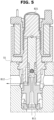
- FIG. 5 is an operation state diagram of the connection valve part according to an embodiment of the present disclosure.
- a supply port part 66 may be formed in the auxiliary block part 60.
- the open and close valve part 821 of the connection valve part 82 may be mounted on the supply port part 66.
- the supply port part 66 may include a first supply port part 661 that forms a hole by being processed from the first surface 51 and a second supply port part 662 that is extended from the first supply port part 661.
- the first supply port part 661 may be connected to the second line part 812 of the connection line part 81.
- the second supply port part 662 may be connected to the first line part 811 of the connection line part 81. Accordingly, a control direction in which pressure that is generated by control of the auxiliary electric part 70, the wheel valve part 92, and the decompression flow channel part 93 is closed by an electromagnetic force of the open and close valve part 821 and a direction in which the pressure acts are identical with each other, which is advantageous for control and a product design. Furthermore, in a normal open state, resistance of a flow channel can be reduced because a direction in which a spring force acts to open the open and close valve part 821 and a direction in which oil introduced from the main braking part 40 passes are identical with each other.
- FIG. 6 is a diagram schematically illustrating the state in which the wheel valve part has been mounted on the auxiliary block part according to an embodiment of the present disclosure.
- FIG. 7 is an operation state diagram of the wheel valve part according to an embodiment of the present disclosure.
- a wheel port part 67 may be formed in the auxiliary block part 60.
- the wheel valve part 92 may be mounted on the wheel port part 67.
- the wheel port part 67 may include a first wheel port part 671 that forms a hole by being processed from the first surface 51 and a second wheel port part 672 that is extended from the first wheel port part 671.
- the first wheel port part 671 may be connected to the second wheel line part 912.
- the second wheel port part 672 may be connected to the first wheel line part 911.
- a direction in which pressure acts and a direction in which a spring force for closing the valve acts are identical with each other, which is advantageous for control of the wheel valve part 92. Furthermore, a direction in which an electromagnetic force of the wheel valve part 92 acts when oil discharged from the auxiliary electric part 70 passes is identical, which is advantageous for control.
- oil for braking may be supplied to the wheel cylinder part 100 by the driving of the auxiliary braking part 50. At this time, the supply of oil to the main braking part 40 can be blocked, and oil that has been stored in the storage part 30 can be supplied.
Landscapes
- Engineering & Computer Science (AREA)
- Transportation (AREA)
- Mechanical Engineering (AREA)
- Valves And Accessory Devices For Braking Systems (AREA)
- Regulating Braking Force (AREA)
Abstract
A brake apparatus (1) includes a pedal part (10) capable of being pressurized, a master cylinder part (20) in which pressure of oil is amplified by the pedal part, a storage part (30) that is connected to the master cylinder part and in which oil is temporarily stored, a main braking part (40) connected to the master cylinder part and supplied with oil therefrom, connected to some of a plurality of wheel cylinder parts (100), and configured to supply oil for braking to some of the plurality of wheel cylinder parts, and an auxiliary braking part (50) configured to connect the main braking part and remaining wheel cylinder parts of the plurality of wheel cylinder parts, connected to the storage part, and configured to amplify pressure of oil by self-driving when an error occurs in the main braking part.
Description
- Exemplary embodiments of the present disclosure relate to a brake apparatus for a vehicle, and more particularly, to a brake apparatus for a vehicle, which can prevent an accident in an autonomous vehicle because auxiliary braking is performed when an error occurs in main braking.
- In general, in a hydraulic brake apparatus, when a driver steps on a pedal, the pressure of oil is amplified through a master cylinder. The amplified pressure of the oil is supplied to each wheel, so that a braking force is generated. Furthermore, braking pressure is provided to each wheel by the pressure of oil that is generated by the driving of a motor.
- In such a hydraulic brake apparatus, a motor pump and various types of valves are mounted on a housing block in which a flow channel is formed. The hydraulic brake apparatus is connected to each wheel. The master cylinder is connected to a flow channel of the housing block through a hydraulic line.
- However, in the conventional hydraulic brake apparatus, an accident may occur because auxiliary braking is not performed when an error occurs in main braking. In particular, an autonomous vehicle has a problem in that vehicle braking is impossible if the motor is not driven in main braking. Accordingly, there is a need for solving the problem.
- The Background Technology of the present disclosure is disclosed in
Korean Patent Application Publication No. 2007-0104982 (October 30, 2007 - Various embodiments are directed to providing a brake apparatus for a vehicle, which can prevent an accident in an autonomous vehicle because auxiliary braking is performed when an error occurs in main braking.
- In an embodiment, a brake apparatus for a vehicle may include a pedal part capable of being pressurized, a master cylinder part in which pressure of oil is amplified by the pedal part, a storage part that is connected to the master cylinder part and in which oil is temporarily stored, a main braking part connected to the master cylinder part and supplied with oil therefrom, connected to some of a plurality of wheel cylinder parts, and configured to supply oil for braking to some of the plurality of wheel cylinder parts, and an auxiliary braking part configured to connect the main braking part and remaining wheel cylinder parts of the plurality of wheel cylinder parts, connected to the storage part, and configured to amplify pressure of oil by self-driving when an error occurs in the main braking part.
- The auxiliary braking part may include an auxiliary block part connected to the main braking part and the wheel cylinder part, an auxiliary electric part mounted on the auxiliary block part and driven when power is applied thereto, an auxiliary flow channel part formed in the auxiliary block part and configured to supply oil of the main braking part and the storage part to the auxiliary electric part, and a wheel flow channel part formed in the auxiliary block part and configured to provide the wheel cylinder part with oil that is discharged by the auxiliary electric part.
- The auxiliary flow channel part may include a connection line part configured to connect the main braking part and the auxiliary electric part and to provide the oil that is supplied by the main braking part with guidance and a connection valve part formed in the connection line part and configured to adjust the amount of oil that passes through the connection line part by opening and closing the connection line part.
- The auxiliary flow channel part may further include a reservoir connection part configured to connect the connection line part and the storage part.
- The wheel flow channel part may include a wheel line part configured to connect the auxiliary electric part and the wheel cylinder part and a wheel valve part formed in the wheel line part and configured to adjust the amount of oil that passes through the wheel line part.
- The wheel flow channel part may further include a decompression flow channel part configured to connect the auxiliary flow channel part and the wheel flow channel part and to decompress oil.
- A pump port part on which the auxiliary electric part is mountable may be formed in the auxiliary block part. The connection valve part may be disposed over a first axis of the pump port part.
- The connection valve parts may be disposed to be symmetrical to each other on the basis of a second axis of the pump port part.
- A pump port part on which the auxiliary electric part is mountable may be formed in the auxiliary block part. The wheel valve part may be disposed under a first axis of the pump port part.
- The wheel valve parts may be disposed to be symmetrical to each other on the basis of a second axis of the pump port part.
- In the brake apparatus for a vehicle according to an embodiment of the present disclosure, when an error occurs in the main braking part, oil for braking can be supplied to the wheel cylinder part by the driving of the auxiliary braking part. At this time, the supply of oil to the main braking part can be blocked, and oil that has been stored in the storage part can be supplied.
-
-
FIG. 1 is a diagram schematically illustrating a brake apparatus for a vehicle according to an embodiment of the present disclosure. -
FIG. 2 is a diagram schematically illustrating an auxiliary braking part according to an embodiment of the present disclosure. -
FIG. 3 is a diagram schematically illustrating an auxiliary block part according to an embodiment of the present disclosure. -
FIG. 4 is a diagram schematically illustrating the state in which a connection valve part has been mounted on the auxiliary block part according to an embodiment of the present disclosure. -
FIG. 5 is an operation state diagram of the connection valve part according to an embodiment of the present disclosure. -
FIG. 6 is a diagram schematically illustrating the state in which a wheel valve part has been mounted on the auxiliary block part according to an embodiment of the present disclosure. -
FIG. 7 is an operation state diagram of the wheel valve part according to an embodiment of the present disclosure. - Hereinafter, a brake apparatus for a vehicle according to an embodiment of the present disclosure will be described with reference to the accompanying drawings. In this process, the thicknesses of lines or the sizes of components illustrated in the drawings may have been exaggerated for the clarity of a description and for convenience' sake. Terms to be described below have been defined by taking into consideration their functions in the present disclosure, and may be changed depending on a user or operator's intention or practice. Accordingly, such terms should be defined based on the overall contents of this specification.
-
FIG. 1 is a diagram schematically illustrating a brake apparatus for a vehicle according to an embodiment of the present disclosure. Referring toFIG. 1 , abrake apparatus 1 for a vehicle according to an embodiment of the present disclosure includes apedal part 10, amaster cylinder part 20, astorage part 30, amain braking part 40, and anauxiliary braking part 50. - The
pedal part 10 may be pressurized. For example, thepedal part 10 may be disposed within a vehicle body, and may be stepped on by a driver while driving. In addition, in an autonomous driving mode, thepedal part 10 may be pressurized. - The pressure of oil within the
master cylinder part 20 may be amplified by thepedal part 10. For example, the pressure of oil that has been stored in themaster cylinder part 20 may be amplified as a cylinder in which two chambers have been formed is pressurized while operating in conjunction with thepedal part 10. - The
storage part 30 may be connected to themaster cylinder part 20, and may temporarily store oil. Thestorage part 30 may be connected to each of the partitioned chambers of themaster cylinder part 20. - The
main braking part 40 may be connected to themaster cylinder part 20 and supplied with oil. Themain braking part 40 may be connected to some of a plurality ofwheel cylinder parts 100, and may provide the wheel cylinder part with oil for braking. For example, when oil having high pressure is supplied to thewheel cylinder part 100, a braking force may be generated in a front wheel or a rear wheel. Thewheel cylinder part 100 may be mounted on each of two front wheels and two rear wheels. Themain braking part 40 may provide oil to thewheel cylinder part 100 that is mounted on one front wheel and one rear wheel. In addition, themain braking part 40 may provide oil to thewheel cylinder part 100 that is mounted on two front wheels or two rear wheels. - The
auxiliary braking part 50 may connect themain braking part 40 and the remaining wheel cylinder parts of the plurality ofwheel cylinder parts 100, and may be connected to thestorage part 30. Theauxiliary braking part 50 may amplify the pressure of oil by self-driving when an error occurs in themain braking part 40. -
FIG. 2 is a diagram schematically illustrating the auxiliary braking part according to an embodiment of the present disclosure. Referring toFIG. 2 , theauxiliary braking part 50 according to an embodiment of the present disclosure may include anauxiliary block part 60, an auxiliaryelectric part 70, an auxiliaryflow channel part 80, and a wheelflow channel part 90. - The
auxiliary block part 60 may be connected to themain braking part 40 and thewheel cylinder part 100. For example, theauxiliary block part 60 may be composed of a square block that is manufactured by an extrusion molding method and subjected to a cutting process and that is made of an aluminum alloy. Theauxiliary block part 60 may be mounted on the vehicle body. A port may be formed in theauxiliary block part 60 by hole processing, so that theauxiliary block part 60 may form a space on which the auxiliaryelectric part 70 is mounted. A circuit that provides oil with guidance, such as the auxiliaryflow channel part 80 or the wheelflow channel part 90, may be formed in theauxiliary block part 60. - The auxiliary
electric part 70 may be mounted on theauxiliary block part 60 and driven when power is applied thereto. The auxiliaryelectric part 70 may include anauxiliary motor part 71 and anauxiliary pump part 72. When power is applied to theauxiliary motor part 71, theauxiliary pump parts 72 that are disposed on both sides of theauxiliary motor part 71 may be driven by eccentric driving, so that oil may be compressed and discharged. - The auxiliary
flow channel part 80 may be formed in theauxiliary block part 60, and may supply oil of themain braking part 40 and thestorage part 30 to the auxiliaryelectric part 70. - The wheel
flow channel part 90 may be formed in theauxiliary block part 60, and may provide thewheel cylinder part 100 with oil that is discharged by the auxiliaryelectric part 70. - The auxiliary
flow channel part 80 according to an embodiment of the present disclosure may include aconnection line part 81 and aconnection valve part 82. - The
connection line part 81 may connect themain braking part 40 and the auxiliaryelectric part 70, and may provide oil that is supplied by themain braking part 40 with guidance. For example, one end of each of the pair ofconnection line parts 81 may be connected to each of a pair offirst port parts 61 that is formed in theauxiliary block part 60. Thefirst port part 61 may be connected to a hydraulic line of themain braking part 40. - The
connection valve part 82 may be formed in theconnection line part 81, and may adjust the amount of oil that passes through theconnection line part 81 by opening and closing theconnection line part 81. For example, when an error occurs in themain braking part 40, theconnection valve part 82 may block theconnection line part 81. Accordingly, the hydraulic line of themain braking part 40 and a hydraulic line of the auxiliaryflow channel part 80 may be separated. - The
connection valve part 82 may include an open andclose valve part 821 and adecompression valve part 822. The open andclose valve part 821 may connect or close a flow channel between themain braking part 40 and the auxiliaryflow channel part 80. Thedecompression valve part 822 may induce oil that passes through theconnection line part 81 to maintain set pressure. - The
connection line part 81 may include afirst line part 811 that connects thefirst port part 61 and the open andclose valve part 821, asecond line part 812 that connects the open andclose valve part 821 and thedecompression valve part 822, and athird line part 813 that connects thedecompression valve part 822 and the auxiliaryelectric part 70. - The auxiliary
flow channel part 80 according to an embodiment of the present disclosure may further include areservoir connection part 85. Thereservoir connection part 85 may connect theconnection line part 81 and thestorage part 30. For example, thereservoir connection part 85 may be connected to asecond port part 62 that is formed in theauxiliary block part 60. Furthermore, a hydraulic line that provides oil of thestorage part 30 with guidance may be connected to thesecond port part 62. Thereservoir connection part 85 may include a firstreservoir connection part 851 and a secondreservoir connection part 852. One end of the firstreservoir connection part 851 may be connected to thesecond port part 62. The secondreservoir connection part 852 may be branched from the firstreservoir connection part 851, and both ends of the secondreservoir connection part 852 may be connected to thethird line parts 813, respectively. - The wheel
flow channel part 90 according to an embodiment of the present disclosure may include awheel line part 91 and awheel valve part 92. - The
wheel line part 91 may connect the auxiliaryelectric part 70 and thewheel cylinder part 100. For example, thewheel line part 91 may have one end connected to the auxiliaryelectric part 70 and the other end connected to athird port part 63 formed in theauxiliary block part 60. Thethird port part 63 may be directly connected to thewheel cylinder part 100 through a hydraulic line. - The
wheel valve part 92 may be formed in thewheel line part 91, and may adjust the amount of oil that passes through thewheel line part 91. For example, thewheel line part 91 may include a firstwheel line part 911 having one end connected to the auxiliaryelectric part 70 and the other end connected to thewheel valve part 92 and a secondwheel line part 912 having one end connected to thewheel valve part 92 and the other end connected to thethird port part 63. - The wheel
flow channel part 90 according to an embodiment of the present disclosure may further a decompressionflow channel part 93. The decompressionflow channel part 93 may connect the auxiliaryflow channel part 80 and thewheel line part 91 and decompress oil. For example, the decompressionflow channel part 93 may include afirst decompression part 931, asecond decompression part 932, and athird decompression part 933. - The
first decompression part 931 may connect the pair ofwheel line parts 91. For example, thefirst decompression part 931 may connect the firstwheel line parts 911 each having one end connected to the auxiliaryelectric part 70 and the other end connected to thewheel valve part 92. - The
second decompression part 932 may have one end connected to thefirst decompression part 931 and the other end connected to theconnection line part 81. For example, thesecond decompression part 932 may be connected to any one of the pair ofthird line parts 813. - The
third decompression part 933 may transmit or block oil depending on set pressure. For example, thethird decompression part 933 may be disposed in thesecond decompression part 932, and may adjust the amount of passage of oil. - As each
third decompression parts 933 is controlled, the auxiliaryelectric part 70 may be used in common. Furthermore, through control of thethird decompression part 933, the connection and separation of oil through thesecond port part 62 are possible, and control of set pressure may be possible. -
FIG. 3 is a diagram schematically illustrating the auxiliary block part according to an embodiment of the present disclosure. Referring toFIGS. 2 and3 , apump port part 65 on which the auxiliaryelectric part 70 is mountable may be formed in theauxiliary block part 60 according to an embodiment of the present disclosure. Theconnection valve part 82 may be disposed over a first axis "x" of thepump port part 65. For example, thepump port part 65 may include a firstpump port part 651 and a secondpump port part 652. The firstpump port part 651 may be formed on afirst surface 51 that corresponds to a front surface or rear surface of theauxiliary block part 60. Theauxiliary motor part 71 may be mounted on the firstpump port part 651. The secondpump port part 652 may be formed on asecond surface 52 that corresponds to a side of theauxiliary block part 60. Theauxiliary pump part 72 may be mounted on the secondpump port part 652. The first axis "x" may mean a middle line of the secondpump port parts 652 that are disposed on both sides of the firstpump port part 651. When theconnection valve part 82 is disposed over the first axis "x", theconnection line part 81 may become close to thefirst port part 61 that is formed on a top surface of theauxiliary block part 60, so that the length of a hydraulic line can be minimized. - The
connection valve parts 82 may be disposed to be symmetrical to each other on the basis of a second axis "y" of thepump port part 65. For example, the second axis "y" may be orthogonal to the first axis "x", and may mean a middle line of the firstpump port part 651. When theconnection valve parts 82 are disposed to be symmetrical to each other on the basis of the second axis "y", a design change range in the existing layout can be reduced. - The
wheel valve part 92 may be disposed under the first axis "x". When thewheel valve part 92 is disposed under the first axis "x", the layout of a hydraulic line with thethird port part 63 that is formed on a bottom surface of theauxiliary block part 60 can be optimized. - The
wheel valve parts 92 may be disposed to be symmetrical to each other on the basis of the second axis "y" of thepump port part 65. When thewheel valve parts 92 are disposed to be symmetrical to each other on the basis of the second axis "y", a design change range in the existing layout can be reduced. -
FIG. 4 is a diagram schematically illustrating the state in which the connection valve part has been mounted on the auxiliary block part according to an embodiment of the present disclosure.FIG. 5 is an operation state diagram of the connection valve part according to an embodiment of the present disclosure. Referring toFIGS. 4 and5 , asupply port part 66 may be formed in theauxiliary block part 60. The open andclose valve part 821 of theconnection valve part 82 may be mounted on thesupply port part 66. Thesupply port part 66 may include a firstsupply port part 661 that forms a hole by being processed from thefirst surface 51 and a secondsupply port part 662 that is extended from the firstsupply port part 661. The firstsupply port part 661 may be connected to thesecond line part 812 of theconnection line part 81. The secondsupply port part 662 may be connected to thefirst line part 811 of theconnection line part 81. Accordingly, a control direction in which pressure that is generated by control of the auxiliaryelectric part 70, thewheel valve part 92, and the decompressionflow channel part 93 is closed by an electromagnetic force of the open andclose valve part 821 and a direction in which the pressure acts are identical with each other, which is advantageous for control and a product design. Furthermore, in a normal open state, resistance of a flow channel can be reduced because a direction in which a spring force acts to open the open andclose valve part 821 and a direction in which oil introduced from themain braking part 40 passes are identical with each other. -
FIG. 6 is a diagram schematically illustrating the state in which the wheel valve part has been mounted on the auxiliary block part according to an embodiment of the present disclosure.FIG. 7 is an operation state diagram of the wheel valve part according to an embodiment of the present disclosure. Referring toFIGS. 6 and7 , awheel port part 67 may be formed in theauxiliary block part 60. Thewheel valve part 92 may be mounted on thewheel port part 67. Thewheel port part 67 may include a firstwheel port part 671 that forms a hole by being processed from thefirst surface 51 and a secondwheel port part 672 that is extended from the firstwheel port part 671. The firstwheel port part 671 may be connected to the secondwheel line part 912. The secondwheel port part 672 may be connected to the firstwheel line part 911. Accordingly, at normal times, a direction in which pressure acts and a direction in which a spring force for closing the valve acts are identical with each other, which is advantageous for control of thewheel valve part 92. Furthermore, a direction in which an electromagnetic force of thewheel valve part 92 acts when oil discharged from the auxiliaryelectric part 70 passes is identical, which is advantageous for control. - In the
brake apparatus 1 for a vehicle according to an embodiment of the present disclosure, when an error occurs in themain braking part 40, oil for braking may be supplied to thewheel cylinder part 100 by the driving of theauxiliary braking part 50. At this time, the supply of oil to themain braking part 40 can be blocked, and oil that has been stored in thestorage part 30 can be supplied. - Although embodiments of the disclosure have been disclosed for illustrative purposes, those skilled in the art will appreciate that various modifications, additions and substitutions are possible, without departing from the scope and spirit of the disclosure as defined in the accompanying claims. Thus, the true technical scope of the disclosure should be defined by the following claims.
Claims (10)
- A brake apparatus for a vehicle, comprising:a pedal part capable of being pressurized;a master cylinder part in which pressure of oil is amplified by the pedal part;a storage part that is connected to the master cylinder part and in which oil is temporarily stored;a main braking part connected to the master cylinder part and supplied with oil therefrom, connected to some of a plurality of wheel cylinder parts, and configured to supply oil for braking to some of the plurality of wheel cylinder parts; andan auxiliary braking part configured to connect the main braking part and remaining wheel cylinder parts of the plurality of wheel cylinder parts, connected to the storage part, and configured to amplify pressure of oil by self-driving when an error occurs in the main braking part.
- The brake apparatus for the vehicle of claim 1, wherein the auxiliary braking part comprises:an auxiliary block part connected to the main braking part and the wheel cylinder part;an auxiliary electric part mounted on the auxiliary block part and driven when power is applied thereto;an auxiliary flow channel part formed in the auxiliary block part and configured to supply oil of the main braking part and the storage part to the auxiliary electric part; anda wheel flow channel part formed in the auxiliary block part and configured to provide the wheel cylinder part with oil that is discharged by the auxiliary electric part.
- The brake apparatus for the vehicle of claim 2, wherein the auxiliary flow channel part comprises:a connection line part configured to connect the main braking part and the auxiliary electric part and to provide the oil that is supplied by the main braking part with guidance; anda connection valve part formed in the connection line part and configured to adjust an amount of oil that passes through the connection line part by opening and closing the connection line part.
- The brake apparatus for the vehicle of claim 3, wherein the auxiliary flow channel part further comprises a reservoir connection part configured to connect the connection line part and the storage part.
- The brake apparatus for the vehicle of any one of claims 2 to 4, wherein the wheel flow channel part comprises:a wheel line part configured to connect the auxiliary electric part and the wheel cylinder part; anda wheel valve part formed in the wheel line part and configured to adjust an amount of oil that passes through the wheel line part.
- The brake apparatus for the vehicle of claim 5, wherein the wheel flow channel part further comprises a decompression flow channel part configured to connect the auxiliary flow channel part and the wheel flow channel part and to decompress oil.
- The brake apparatus for the vehicle of any one of claims 3 to 6, wherein:a pump port part on which the auxiliary electric part is mountable is formed in the auxiliary block part, andthe connection valve part is disposed over a first axis of the pump port part.
- The brake apparatus for the vehicle of claim 7, wherein the connection valve parts are disposed to be symmetrical to each other on the basis of a second axis of the pump port part.
- The brake apparatus for the vehicle of any one of claims 5 to 8, wherein:a pump port part on which the auxiliary electric part is mountable is formed in the auxiliary block part, andthe wheel valve part is disposed under a first axis of the pump port part.
- The brake apparatus for the vehicle of claim 9, wherein the wheel valve parts are disposed to be symmetrical to each other on the basis of a second axis of the pump port part.
Applications Claiming Priority (1)
| Application Number | Priority Date | Filing Date | Title |
|---|---|---|---|
| KR1020230191417A KR20250100165A (en) | 2023-12-26 | 2023-12-26 | Hydraulic brake device for vehicle |
Publications (1)
| Publication Number | Publication Date |
|---|---|
| EP4578747A1 true EP4578747A1 (en) | 2025-07-02 |
Family
ID=91469967
Family Applications (1)
| Application Number | Title | Priority Date | Filing Date |
|---|---|---|---|
| EP24180966.4A Pending EP4578747A1 (en) | 2023-12-26 | 2024-06-10 | Brake apparatus for vehicle |
Country Status (4)
| Country | Link |
|---|---|
| US (1) | US20250206278A1 (en) |
| EP (1) | EP4578747A1 (en) |
| KR (1) | KR20250100165A (en) |
| CN (1) | CN120207292A (en) |
Citations (5)
| Publication number | Priority date | Publication date | Assignee | Title |
|---|---|---|---|---|
| KR20070104982A (en) | 2006-04-24 | 2007-10-30 | 주식회사 만도 | Valve controls of electronic hydraulic brake units |
| US11772623B2 (en) * | 2019-10-08 | 2023-10-03 | Hyundai Mobis Co., Ltd. | Electronic hydraulic brake device |
| US11814022B2 (en) * | 2021-02-25 | 2023-11-14 | Hyundai Mobis Co., Ltd. | Hydraulic block of electronic brake system for vehicle |
| US20230398971A1 (en) * | 2022-06-13 | 2023-12-14 | Hyundai Mobis Co., Ltd. | Electro-hydraulic brake device |
| US20230398972A1 (en) * | 2022-06-13 | 2023-12-14 | Hyundai Mobis Co., Ltd. | Electro-hydraulic brake device |
-
2023
- 2023-12-26 KR KR1020230191417A patent/KR20250100165A/en active Pending
-
2024
- 2024-06-10 EP EP24180966.4A patent/EP4578747A1/en active Pending
- 2024-06-24 US US18/751,941 patent/US20250206278A1/en active Pending
- 2024-06-25 CN CN202410828977.6A patent/CN120207292A/en active Pending
Patent Citations (5)
| Publication number | Priority date | Publication date | Assignee | Title |
|---|---|---|---|---|
| KR20070104982A (en) | 2006-04-24 | 2007-10-30 | 주식회사 만도 | Valve controls of electronic hydraulic brake units |
| US11772623B2 (en) * | 2019-10-08 | 2023-10-03 | Hyundai Mobis Co., Ltd. | Electronic hydraulic brake device |
| US11814022B2 (en) * | 2021-02-25 | 2023-11-14 | Hyundai Mobis Co., Ltd. | Hydraulic block of electronic brake system for vehicle |
| US20230398971A1 (en) * | 2022-06-13 | 2023-12-14 | Hyundai Mobis Co., Ltd. | Electro-hydraulic brake device |
| US20230398972A1 (en) * | 2022-06-13 | 2023-12-14 | Hyundai Mobis Co., Ltd. | Electro-hydraulic brake device |
Also Published As
| Publication number | Publication date |
|---|---|
| US20250206278A1 (en) | 2025-06-26 |
| CN120207292A (en) | 2025-06-27 |
| KR20250100165A (en) | 2025-07-03 |
Similar Documents
| Publication | Publication Date | Title |
|---|---|---|
| US11485336B2 (en) | Hydraulic block for redundancy of electronic braking device for vehicle | |
| US11772623B2 (en) | Electronic hydraulic brake device | |
| US12370989B2 (en) | Electro-hydraulic brake device | |
| US11926295B2 (en) | Electro-hydraulic brake device | |
| US10202109B2 (en) | Brake system for a vehicle and method for operating a brake system for a vehicle | |
| US20260021797A1 (en) | Brake apparatus for vehicle | |
| US5979998A (en) | Hydraulic pressure control system for a vehicle | |
| JP2597958B2 (en) | Brake pressure control device | |
| JP2895770B2 (en) | Anti-skid hydraulic pressure control device | |
| JPS62181951A (en) | Tandem master cylinder with booster | |
| KR20090009851A (en) | Hydraulic braking system | |
| EP4578747A1 (en) | Brake apparatus for vehicle | |
| JP2002362353A (en) | Braking oil pressure adjusting device for automobile | |
| US5184877A (en) | Hydraulic braking pressure control device | |
| KR100285181B1 (en) | Braking system | |
| EP1375283A2 (en) | Brake system for a vehicle having an integral precharge pump and back-flow protection | |
| US20250050856A1 (en) | Electronic hydraulic brake apparatus | |
| US12427961B2 (en) | Brake for vehicle and control method therefor | |
| KR102599297B1 (en) | Brake traction control system | |
| JP7552344B2 (en) | Vehicle Brake Device | |
| KR200296177Y1 (en) | Modulator block of anti-lock brake system | |
| JPH0612236U (en) | Slip controller | |
| KR100482958B1 (en) | Electronic Control Brake System for Automobile | |
| JPH10100880A (en) | Brake fluid pressure controller | |
| JPH01101256A (en) | Fluid pressure braking device |
Legal Events
| Date | Code | Title | Description |
|---|---|---|---|
| PUAI | Public reference made under article 153(3) epc to a published international application that has entered the european phase |
Free format text: ORIGINAL CODE: 0009012 |
|
| STAA | Information on the status of an ep patent application or granted ep patent |
Free format text: STATUS: THE APPLICATION HAS BEEN PUBLISHED |
|
| AK | Designated contracting states |
Kind code of ref document: A1 Designated state(s): AL AT BE BG CH CY CZ DE DK EE ES FI FR GB GR HR HU IE IS IT LI LT LU LV MC ME MK MT NL NO PL PT RO RS SE SI SK SM TR |
|
| STAA | Information on the status of an ep patent application or granted ep patent |
Free format text: STATUS: REQUEST FOR EXAMINATION WAS MADE |
|
| 17P | Request for examination filed |
Effective date: 20251230 |